
TJM
-
Posts
362 -
Joined
-
Last visited
Content Type
Profiles
Forums
Gallery
Events
Everything posted by TJM
-
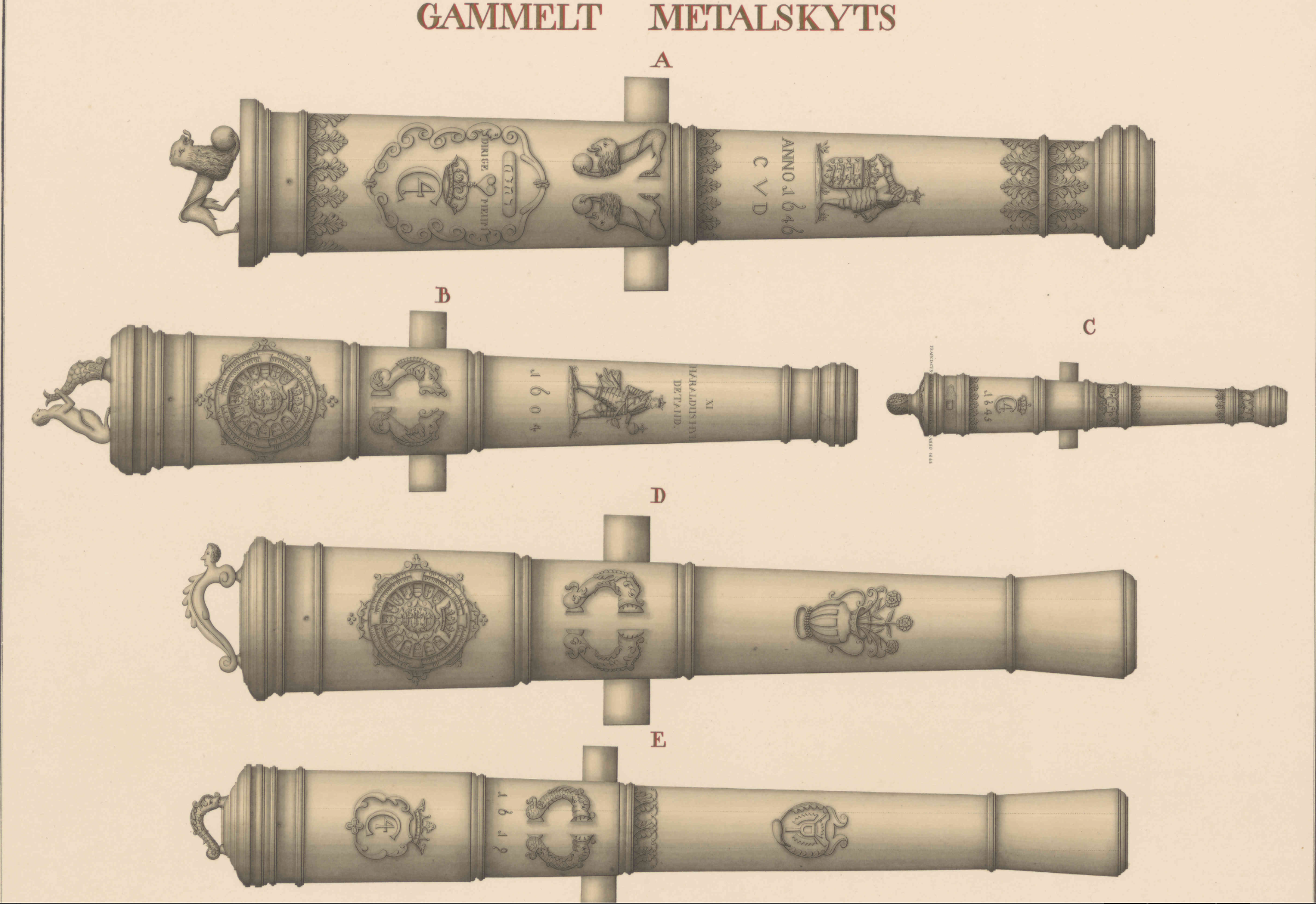
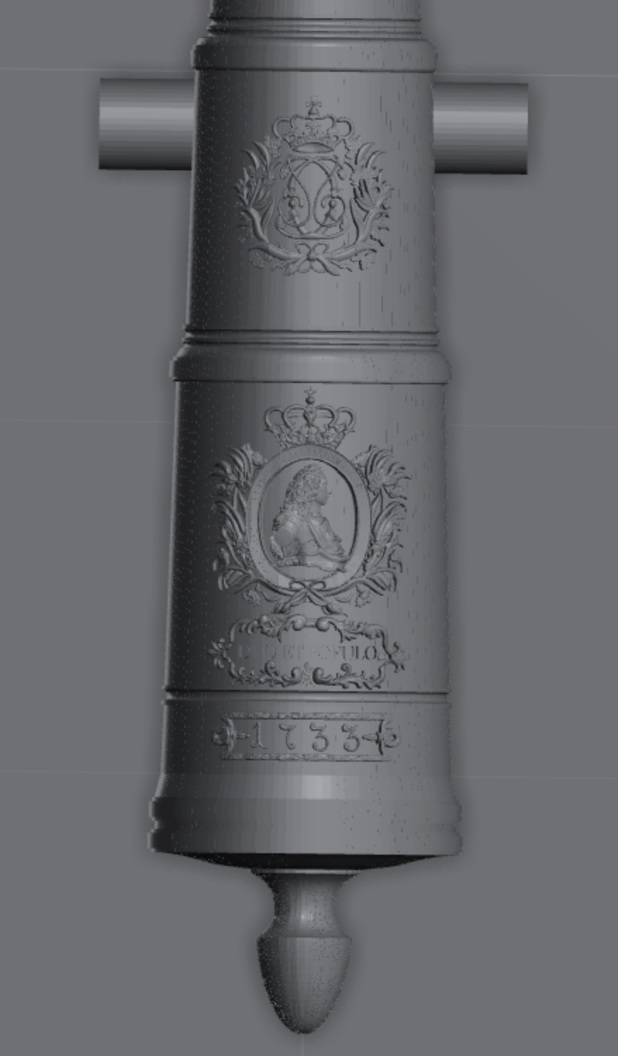
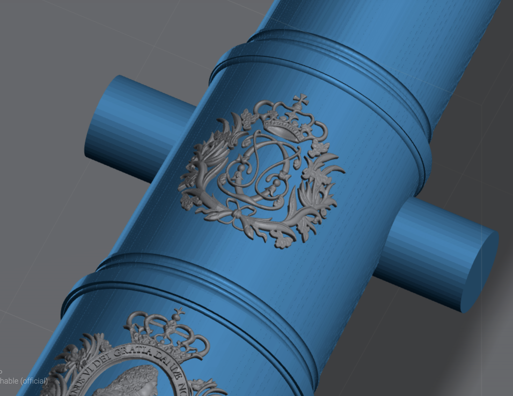
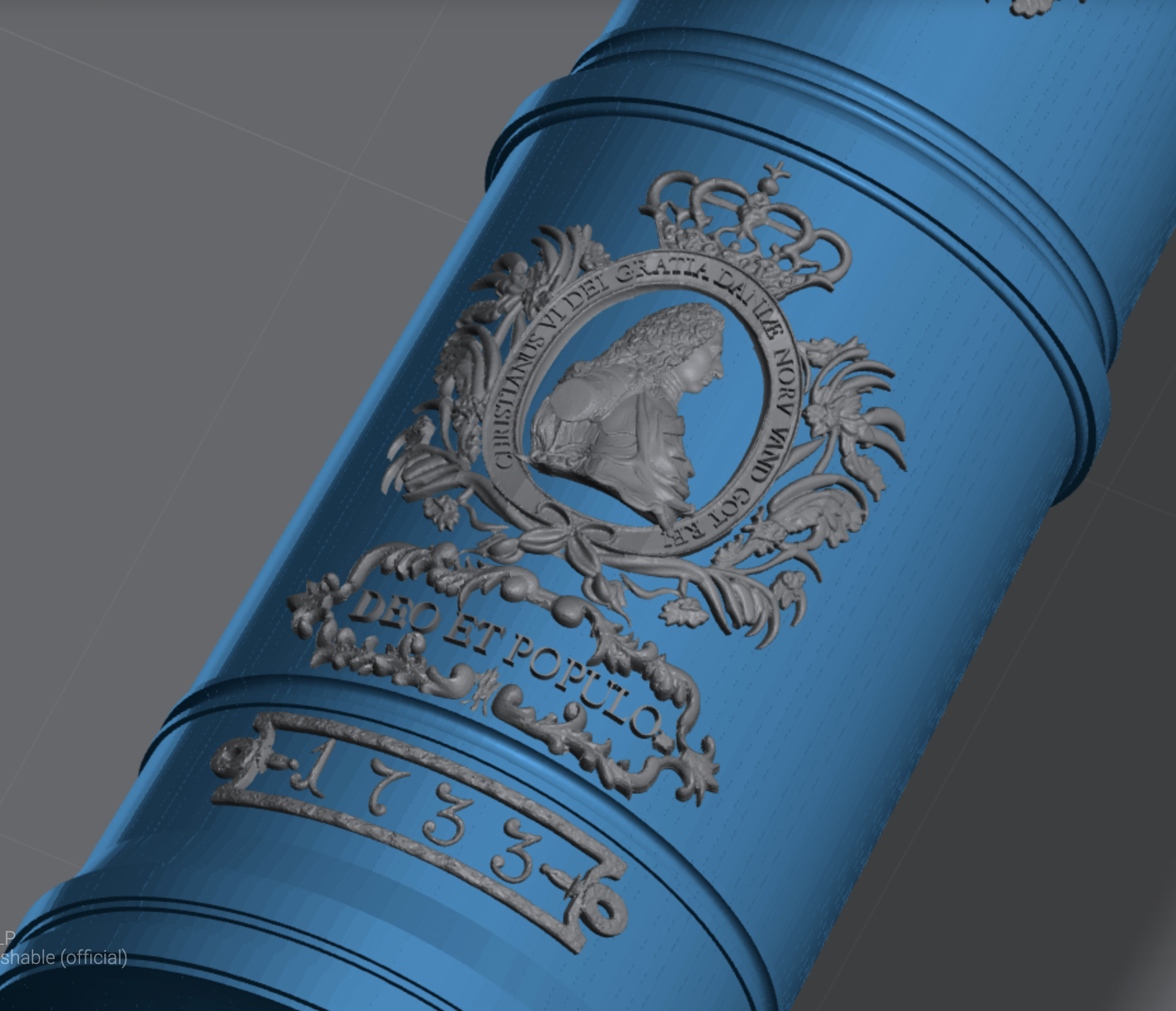
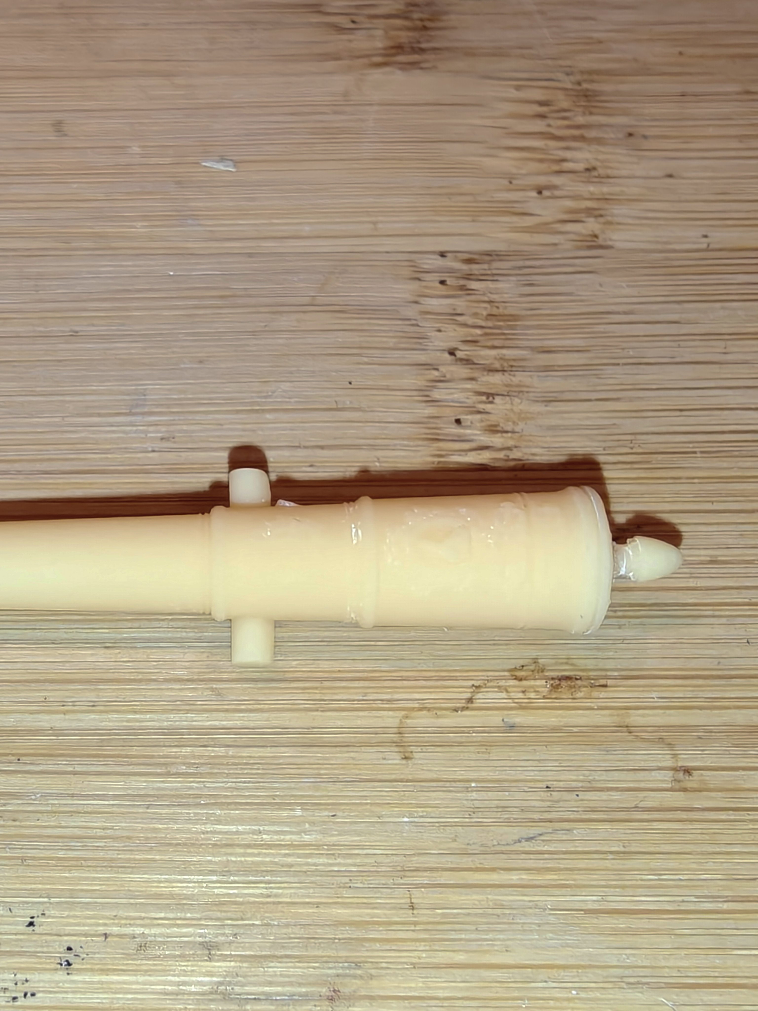
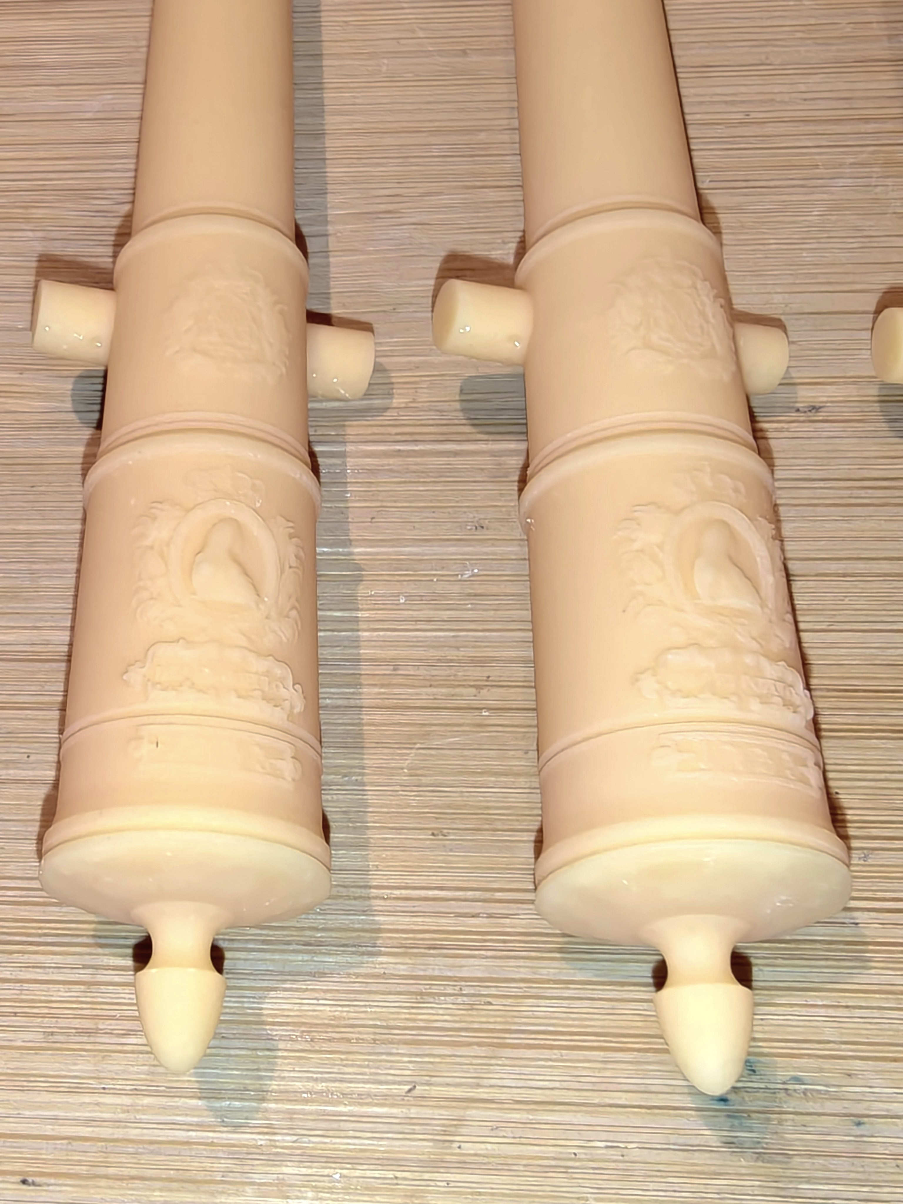
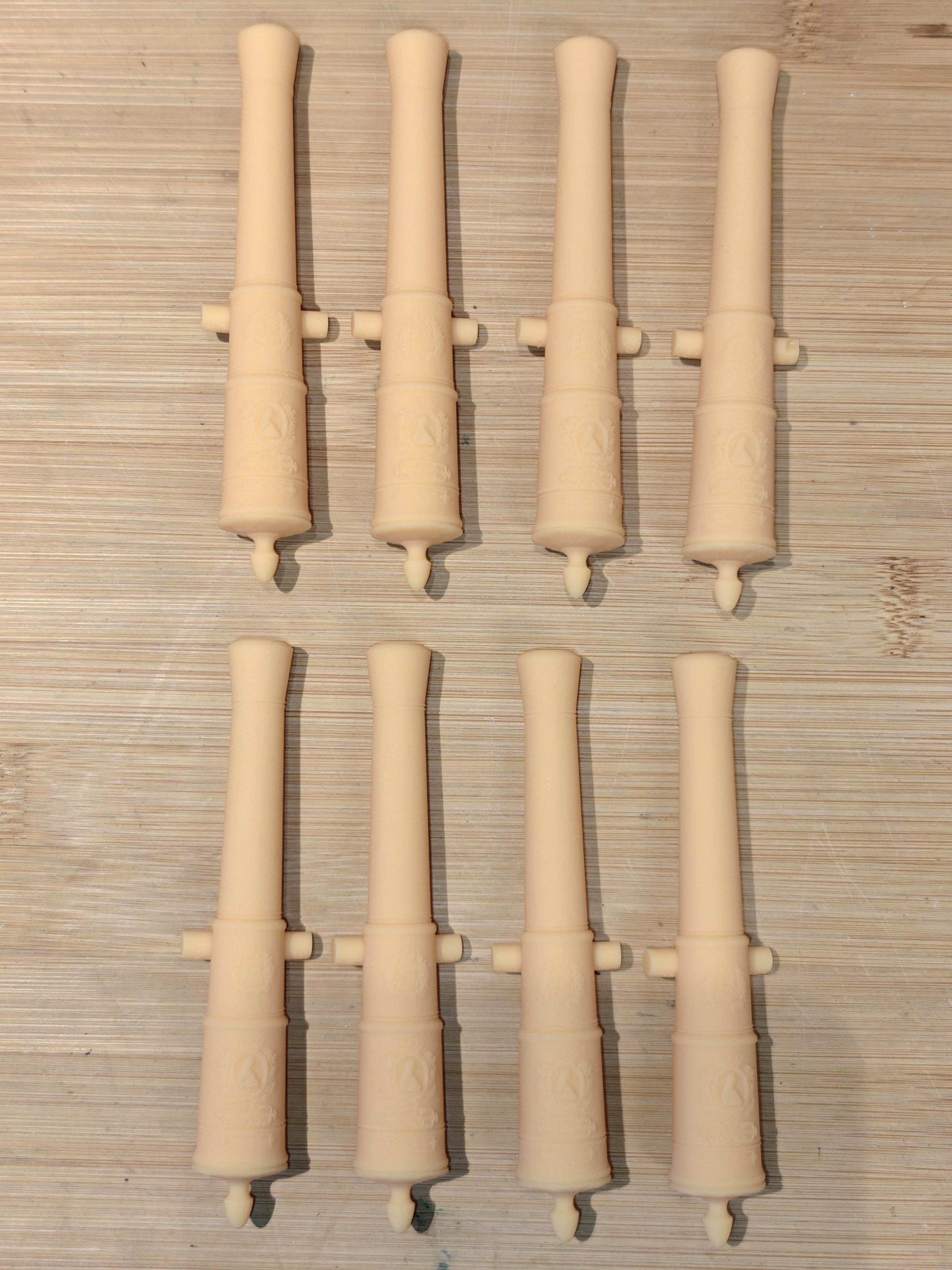
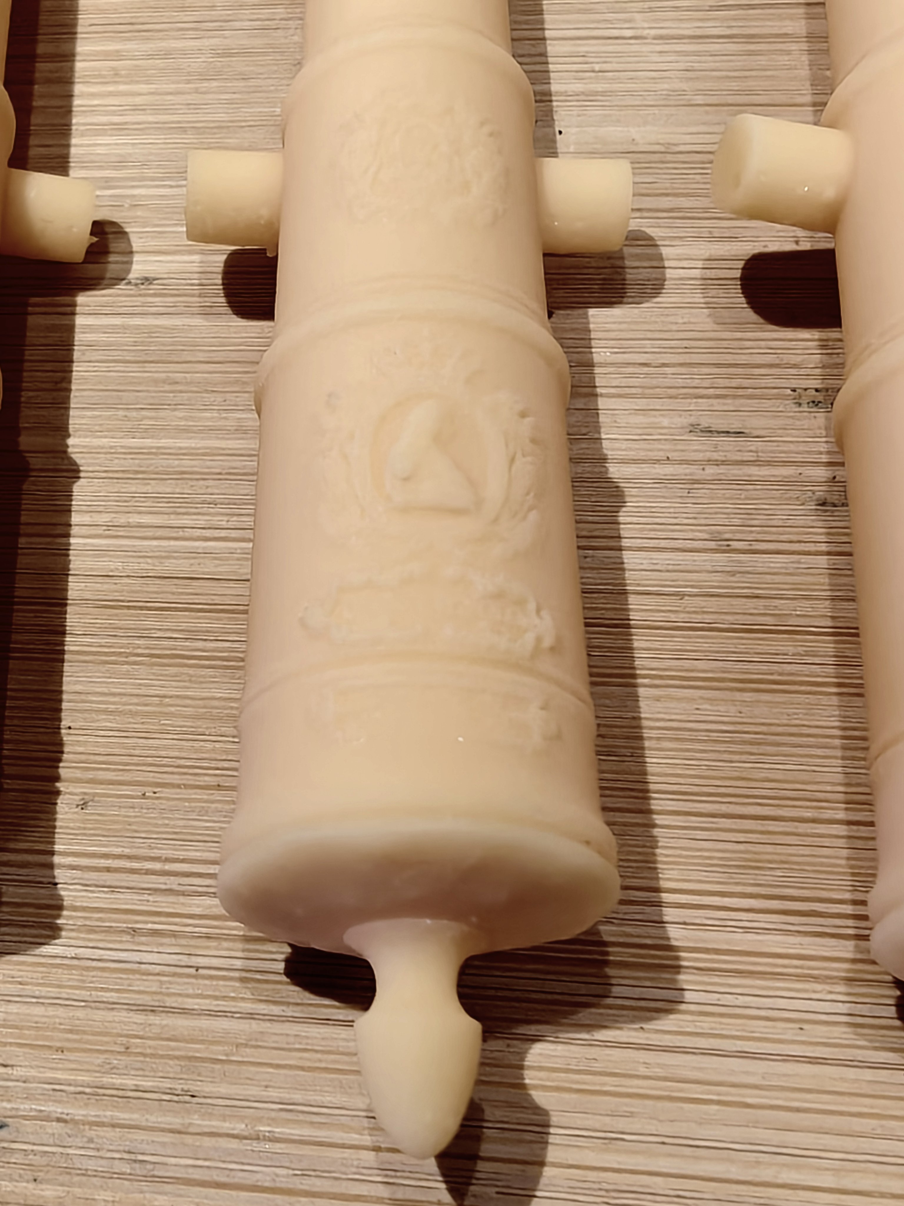
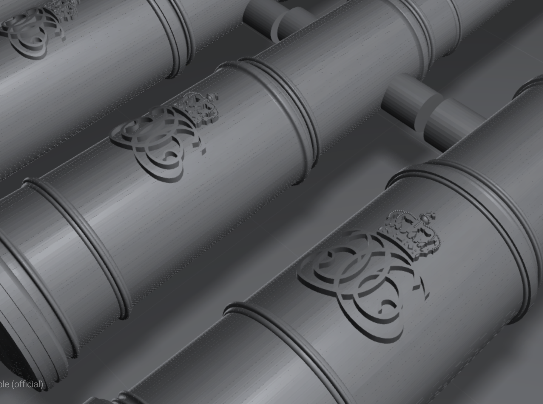
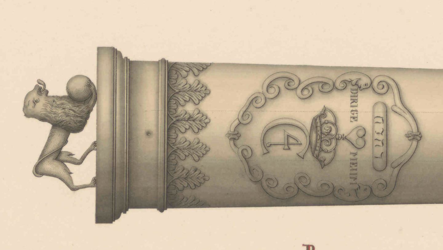
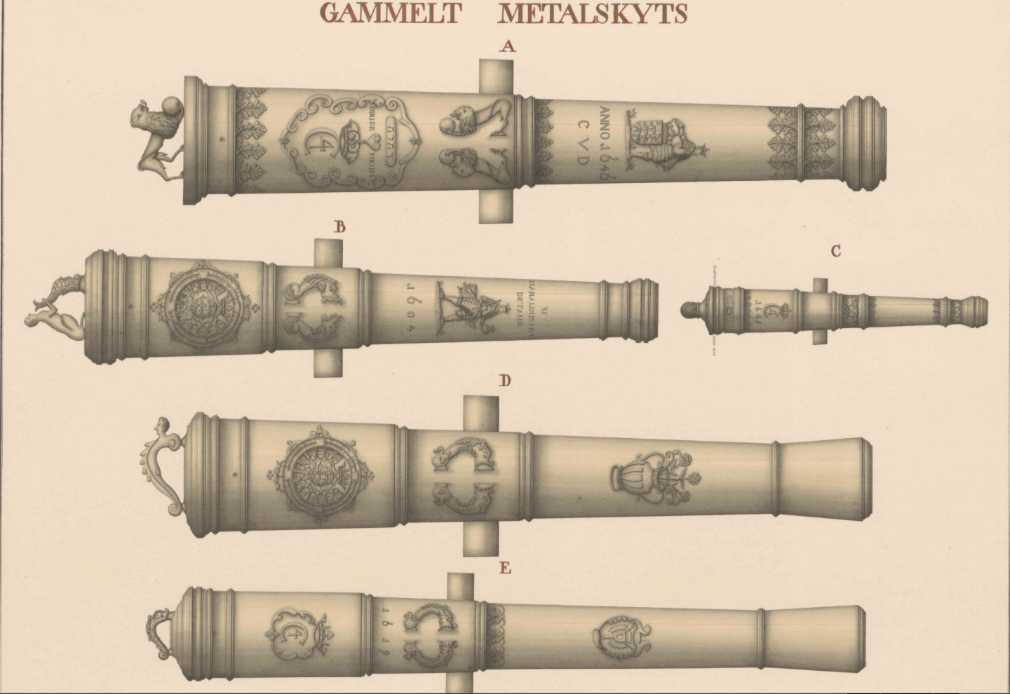
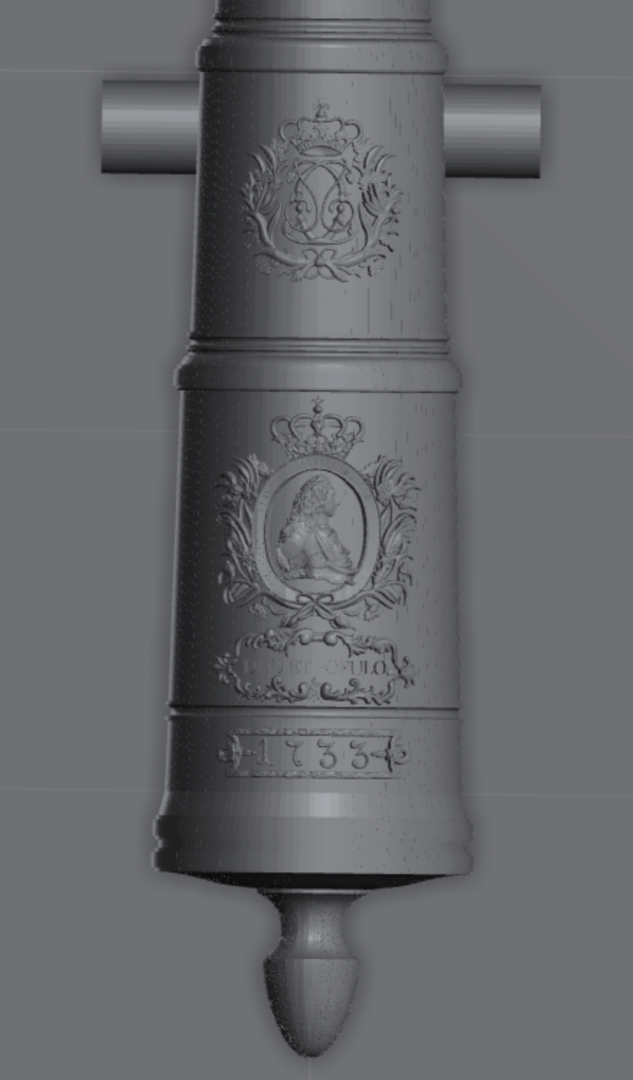
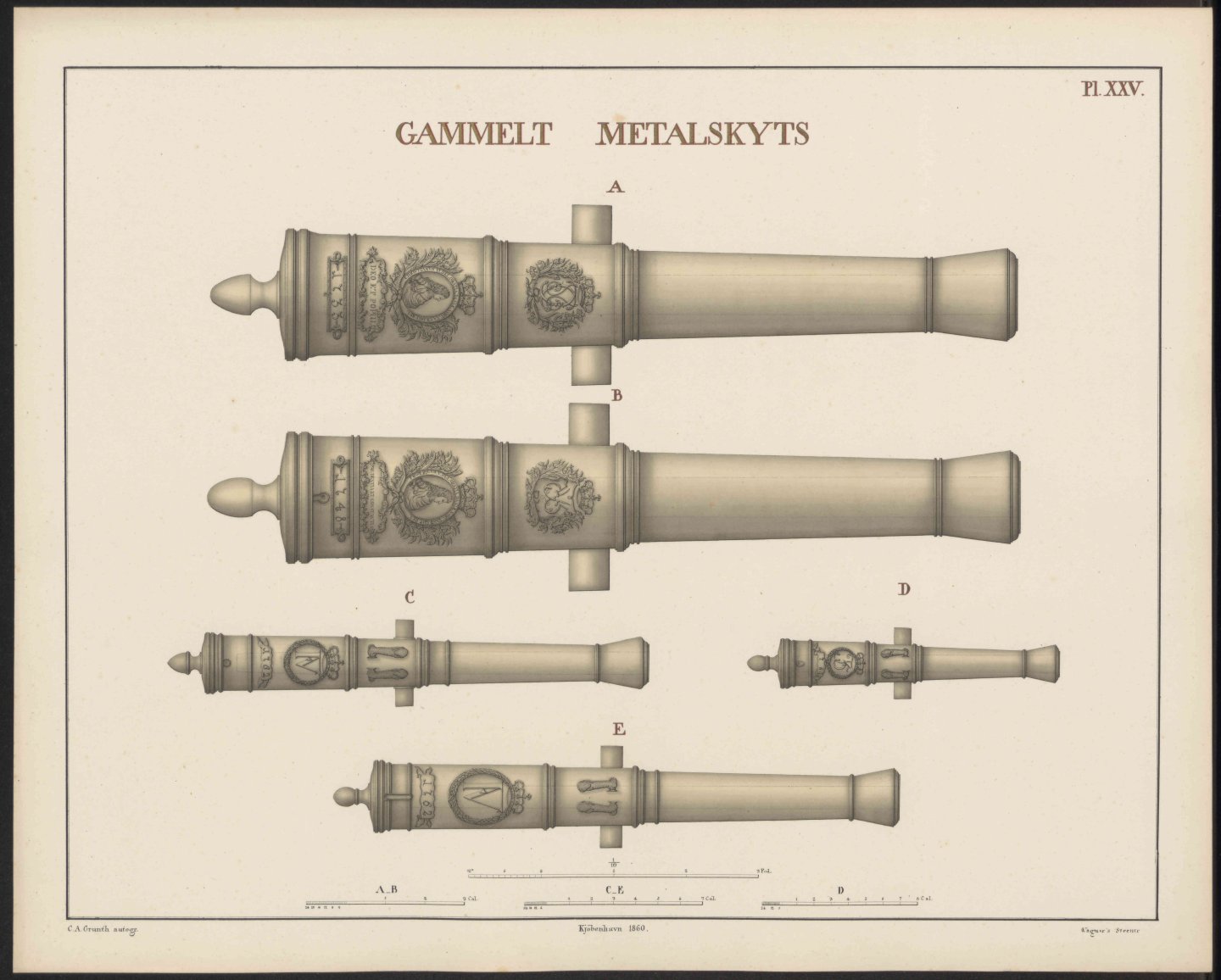
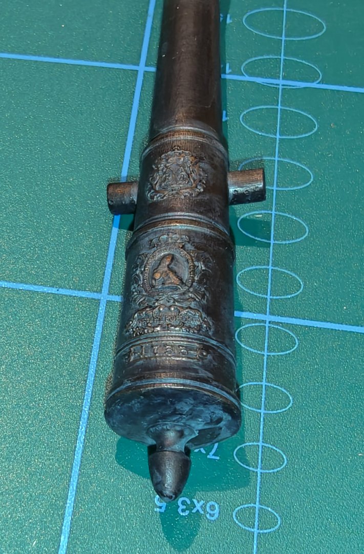
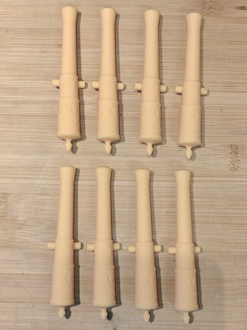
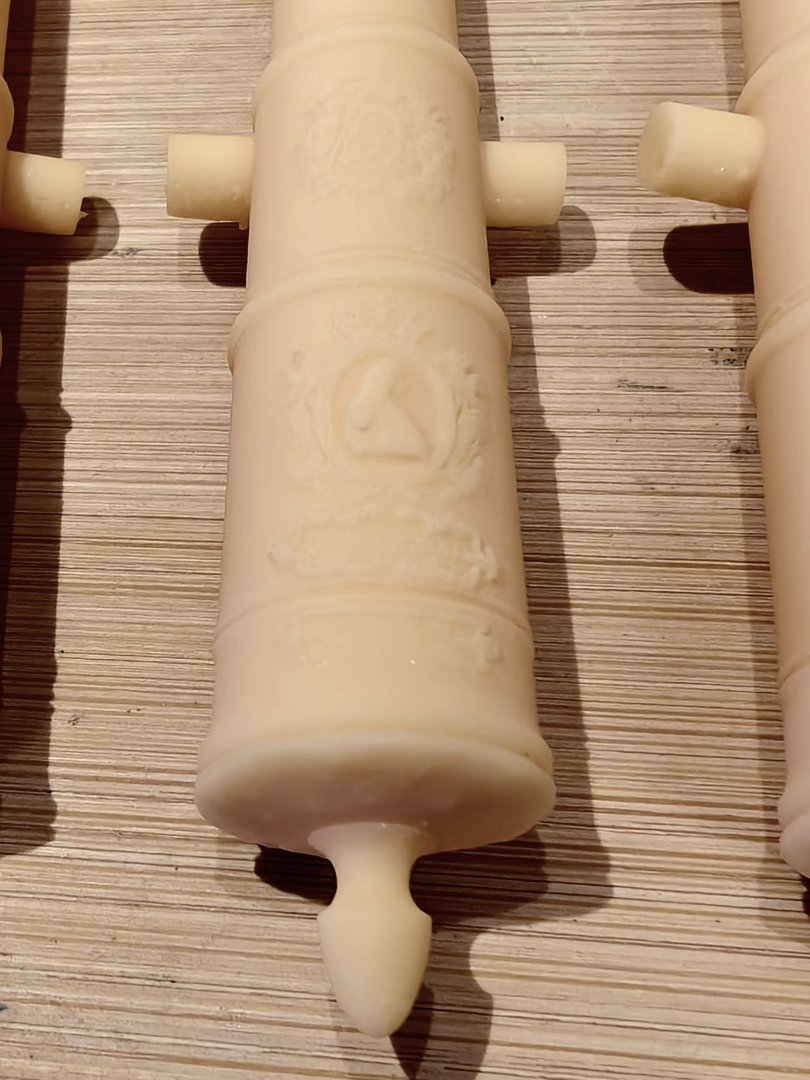
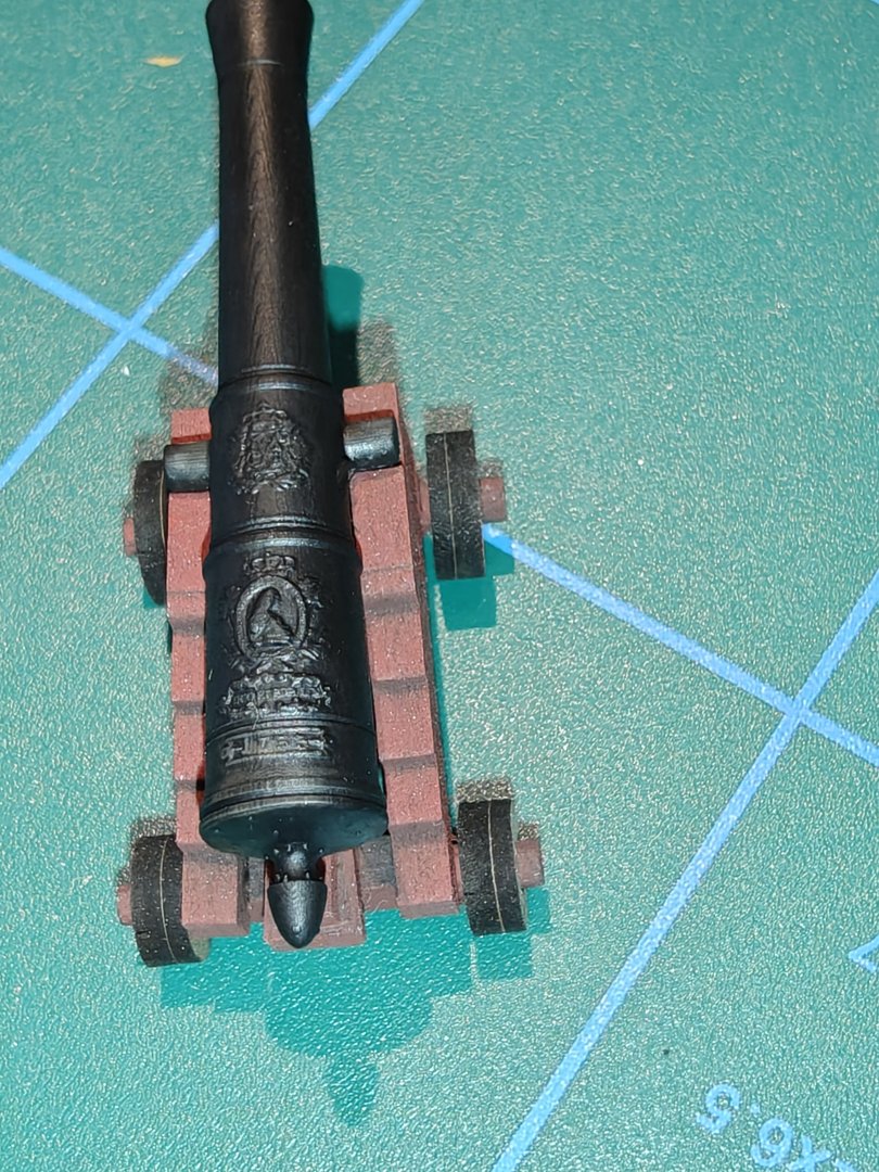
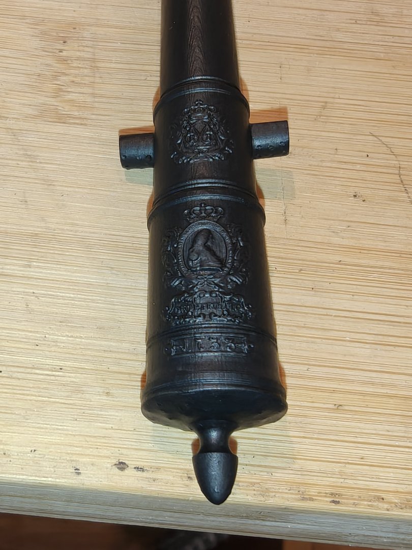
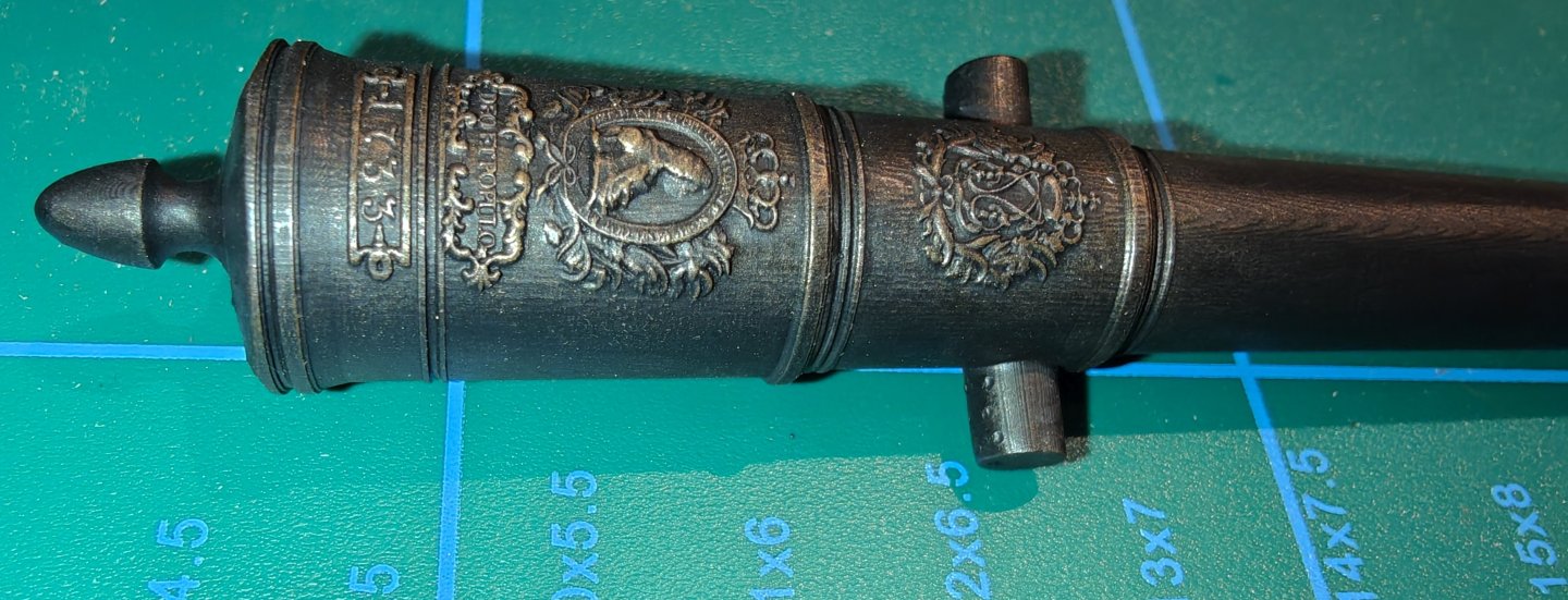
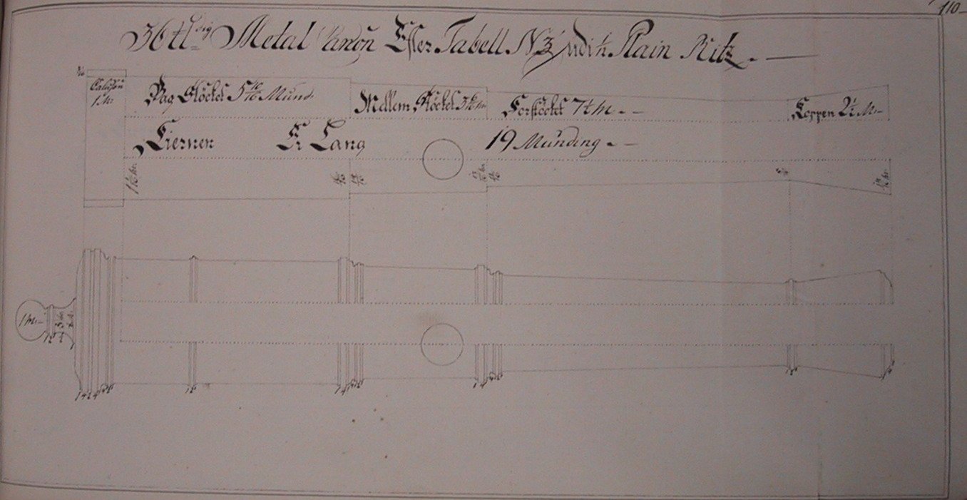
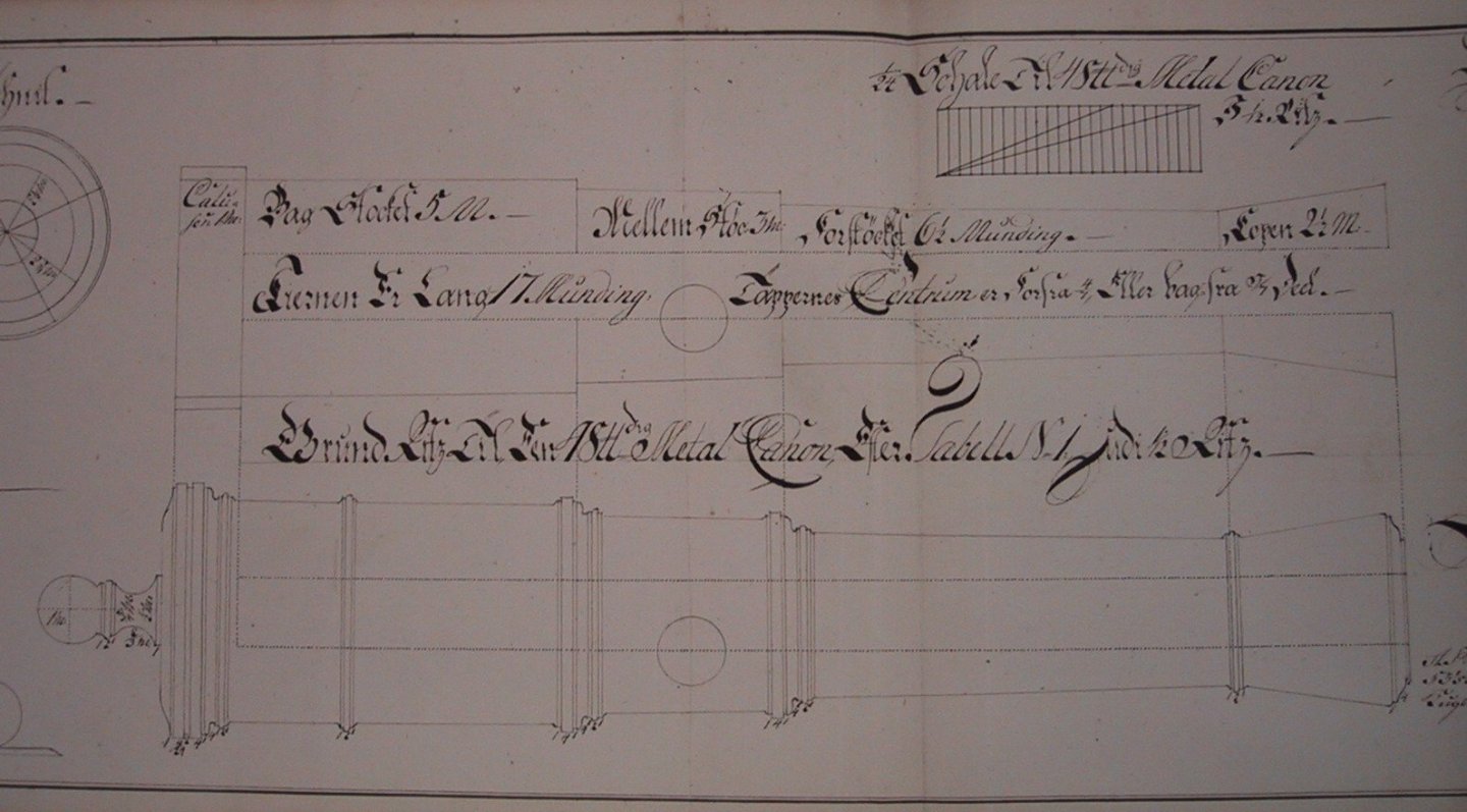
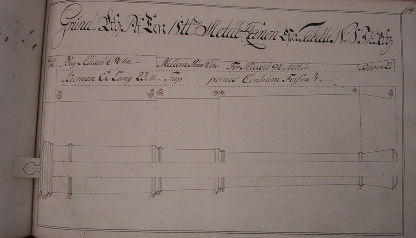
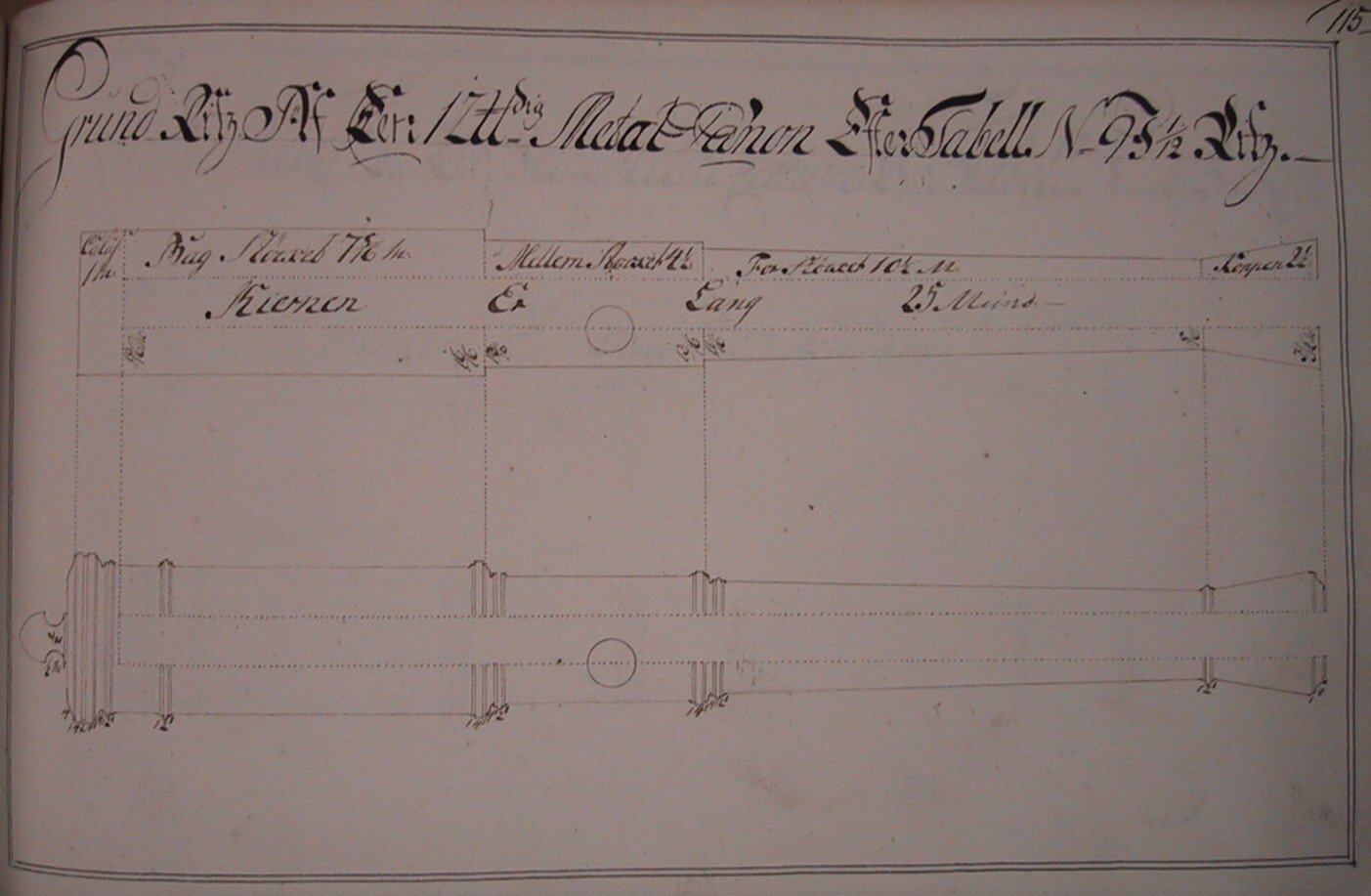
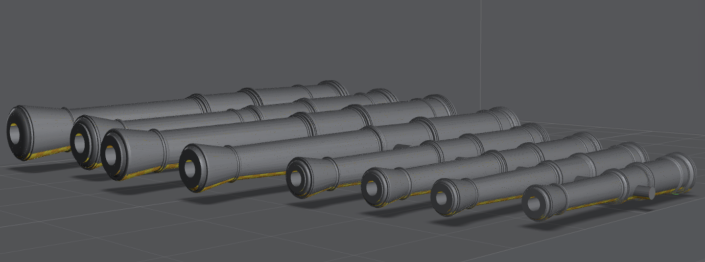
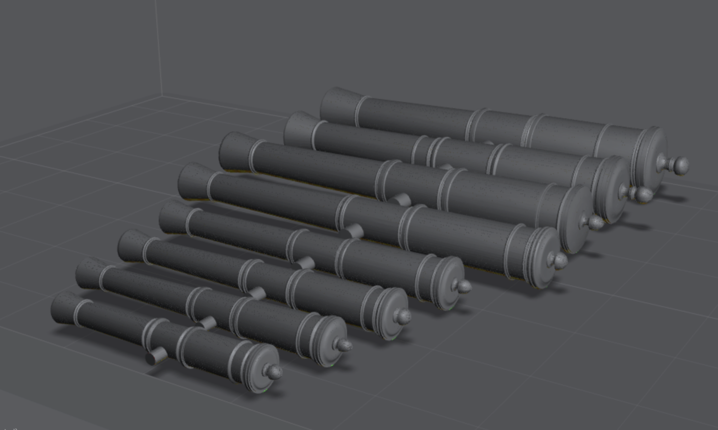
Time for little update. With a lot of pictures! I have been looking for a specific collection of lithographies from 1860 depicting Danish bronze cannon - it is called 'Gammelt Dansk Metalskyts fra det XVIde-XVIIIde Århundrede' which translates to 'Old Danish Metal Artillery from the 16th-18th century'. 'Metal' here means bronze, as opposed to iron. I found the the royal library had several copies, but none were scanned. It turns out they offer a scanning service free of charge, at least for some documents, so I just placed a request and 3 days later I received an email with a lik to a nice, high resolution PDF scan! To say I was happy is an understatement! The drawings are absolutely wonderfull, here's a taste (btw, it is fully permissable to reproduce these for any purpose, as long as credit is given to the royal library - you can find the work now as open access here)here : These are primarily from the 1600's as these from the time of Christian IV, but there are a few from the 1700's as well, and one from the time of Christian VI - basically corresponding to the 36 pounder I posted before - except now I can see the excact decoration of that cannon - the top one in this image: Quite a bit more than just a monogram! Fortunately this is exactly the kind of thing Meshy can help with. I made a total of 5 Meshy runs for various parts of the decoration: 1) the year and frame 2) the motto frame 3) wreath and crown (blank oval) 4) the portrait of Chr. VI 5) the monogram Based on the mothly subscription cost, this is $2 worth of AI help 😁 Then it is a question of 'wrapping' the assets around the gun barrel and composing the whole model. Somone who knows Blender and the likes can do this seamlessly - I just chop the assets into strips/pieces and angle them to get an overall curve. That is a very crude way to du it, but at our modelling scales, it works just fine. Here's a few shots of the 3D model: The text is made seperately, drawn in CAD, extruded, imported and placed correctly. I am quite happy with how this turned out! Here's a 1:1 comparison with the drawing: So, does it print? I chose this particular cannon as I have been helping @Beckmann with cannons for his Tre Kroner and now that I had the actual drawing of the 36 pounder, it was obvious to try to make this one. I have printed a set of 1/32 scale for Beckmann and a single 1/64 scale, just to see what would show at that scale: It is very hard to see the details on the beige resin, but it shows better under the UV curing light: Painted black: Bronze highlights: Weathered: (this might require some work to get good...) Remember, these are macro shots, and it looks a bit rough in places and with the stark flash light, print layer lines are showing quite prominently in the photos - they are almost invisible in real life. I am also a bit limitet by the 50 mu resolution of my printer - higher resolution of down to 14-18 mu pixels are common for 8K-16K printers and that would surely improve the final print quality! Finally, here are some images of the 1/64 scale print: The guy at the back, for scale, is also made with Meshy, based on a ChatGPT made image - double AI! 😅 Due to the enormous polygon count (2.55 million) , I cannot upload the STL file here - I will try to see if I can re-mesh it but I have not found a reliable program to do that with yet. I will upload if I find a good solution! BR TJM


-
I will be very interested to see which ship this will be! I really like the ship design of this period and not a lot of (modern) kits are available from this period.
-
Here is a bit of background on A. Turesen (his name is given as both 'Anders' and 'Andreas' in the sources). Since Judichær became the first Fabriksmester around 1700, the position had been given to someone with deep understanding of the mathematics behind shipbuilding. Aften Knud Benstrup was sacked (mostly unjustified) after an issue with Christianus Sixtus, in 1736, there was no candidate to take over the Fabriksmester position. Or rather, D. Thura took over, but he was not a capable ship designer - his Fyen from 1737, though very pretty, was apparently a very poor sailing ship - and so he held the title in the original meaning: the one who ran the daily operations in the shipyard at Holmen. A Frenchman, Laurent Barbé, was hired but there were numerous collaboration issues with him, Thurah, the Construction Commission etc. He was suspended in 1747 and his ships, while very beautiful, did not perform too well. This is where Turesen and A. gerner (farther of the famous Henrik Gerner) comes into the picture. The following is a translation of a small section of 'Danske Orlogsskibe 1690-1860' During this period, work in the Construction Commission was based on a regulation that had been approved in 1741, in which the standard measurements and the prescribed armament for the various ship classes were listed. In connection with Danneskjold-Samsøe’s departure, Thura sought to exploit the situation. In the autumn of 1746 he submitted to the head of Holmen a proposal that the Construction Commission be dissolved, and that a smaller permanent committee instead be established to supervise shipbuilding and prepare construction drawings. Besides himself, the committee was to consist of Wegersløff, A. Gerner, and A. Turesen. Thura did not succeed in getting this proposal approved. The driving force in shipbuilding at Holmen after Benstrup’s departure was his apprentice, shipbuilder Andreas Turesen. He had worked his way up from shipbuilding apprentice and even became senior shipbuilder. Turesen also proved to be a capable designer and increasingly made his mark. He designed and built the 90-gun ship FRIDERICUS QUINTUS (fig. 33). Already in 1750 the Construction Commission had requested the two shipbuilders P. Brock and P. Kiønig to submit drawings for a 90-gun ship-of-the-line according to the regulations. These were submitted on 30 April of the same year, though only signed by Kiønig. In 1752 the Construction Commission then asked A. Turesen to prepare drawings for a similar ship. These were submitted to the commission on 16 October 1752, after which the commission reviewed both Kiønig’s earlier drawing and Turesen’s. In a letter of 30 October it was recommended to the head of Holmen that Turesen’s drawing be followed. Both sets of drawings were sent with the recommendation, however. Later the Admiralty sent the drawings to the King and recommended that Turesen’s plan be followed. The King agreed and approved it on 13 November 1752. Work on the ship now began, and on 14 January 1753 the Construction Commission was asked to inspect and measure the set-up frames. The ship was launched on 24 November 1753 under the name FRIDERICUS QUINTUS. During the period in question, yet another designer made his mark. This was the naval officer A. Gerner, who, in connection with the collection of four fire-ships in England in 1743, brought home the drawings of the English ship-of-the-line AUGUSTA (fig. 34), a 60-gun ship. This ship was a copy of the French man-of-war SUPERBE. AUGUSTA was built in 1737 and was considered an exceptionally good-sailing ship. A. Gerner had in 1732 been ordered abroad to study ship construction and had been a member of the Construction Commission since 1739. In May 1745 he submitted a drawing for a 50-gun ship of Kiønig’s type, which for Danish conditions was considered to be the best design. He also considered it the most difficult to construct from a shipbuilding-technical standpoint. The drawing was made as a reduction of the drawings for AUGUSTA. The ship FYEN, which became A. Gerner’s only one, was built in 1749 and was considered one of the best sailing ships the Danish-Norwegian fleet had ever had. Until as late as 1767 a total of eight warships were built according to FYEN’s drawings or as reductions of them. A. Gerner did not live to receive recognition for his successful design. He died already in 1749, apparently embittered by the harassment connected with the work on the ship’s construction. It is said that shortly before his death he extracted a promise from his two eldest sons that they would never involve themselves in shipbuilding. The younger sons, including Henrik Gerner (see later), were too young to be bound by such an oath. In 1758 Thura was dismissed as master-builder and instead received the position of commandant at the Tollbooth. Since the establishment of the Construction Commission he had not designed ships. He died only in 1788. End of excerpt. Turesen made 2 ships of the line and 5 frigates, but also constructed 6 of the ships based on A. Gerners Fyen mentioned above! So all in all, he did a lot of the actual work in the 1747-1757 period. He died in 1757 and F.M. Krabbe took over the full Fabriksmester position in 1758.
- 49 replies
-
- 4
-

-

-
- Wildmanden
- Turesen
- (and 1 more)
-
Very interesting Arthur! I look forward to following you progress here! I also really like Turesens designs. He was not acting as 'fabriksmester' as Benstrup or later Krabbe, but he built many of the Ships in that interim period in the 1740's and 1750's, and they seem to have been well liked and generally lasted a long time. If you are looking for information on him, I can paraphrase what 'Danske Orlogsskibe 1690-1860' has to say? Do you have all the drawings of Wildmanden from the archive? Here is the catalog entry for it: It has a very nice set of decorations: Regarding the wales, I think you have it right. The drawing clearly shows the upper edge, just below the gun-ports. The middle frames for (almost?) all Danish ships after around 1730 does not show the thin double wales of the previous century, but rather these thicker ones, or even as this one just thicker planks that get progressively smaller further towards the keel. However it is puzzling, as the contemporary paintings often still show two thin lines for wales all the way up to Gerner's time in the 1770's! Perhaps they were just painted this way at this point in time? I will look for the model of Wilmanden next time I visit Krigsmuseet, though I am not sure exactly when that will be. Also, are you 3D modelling the ship, or are you preparing to make a wooden model as well? BR TJM


- 49 replies
-
- 3
-
-
- Wildmanden
- Turesen
- (and 1 more)
-
Thank you so much @brunnels! The copper roof is actually super easy: any base copper paint and then Citadel Nihilakh Oxide, which is a matt pigment verdigris wash. That's it!
- 148 replies
-
- 2
-
-
-
- Christiania
- Vanguard Models
- (and 1 more)
-
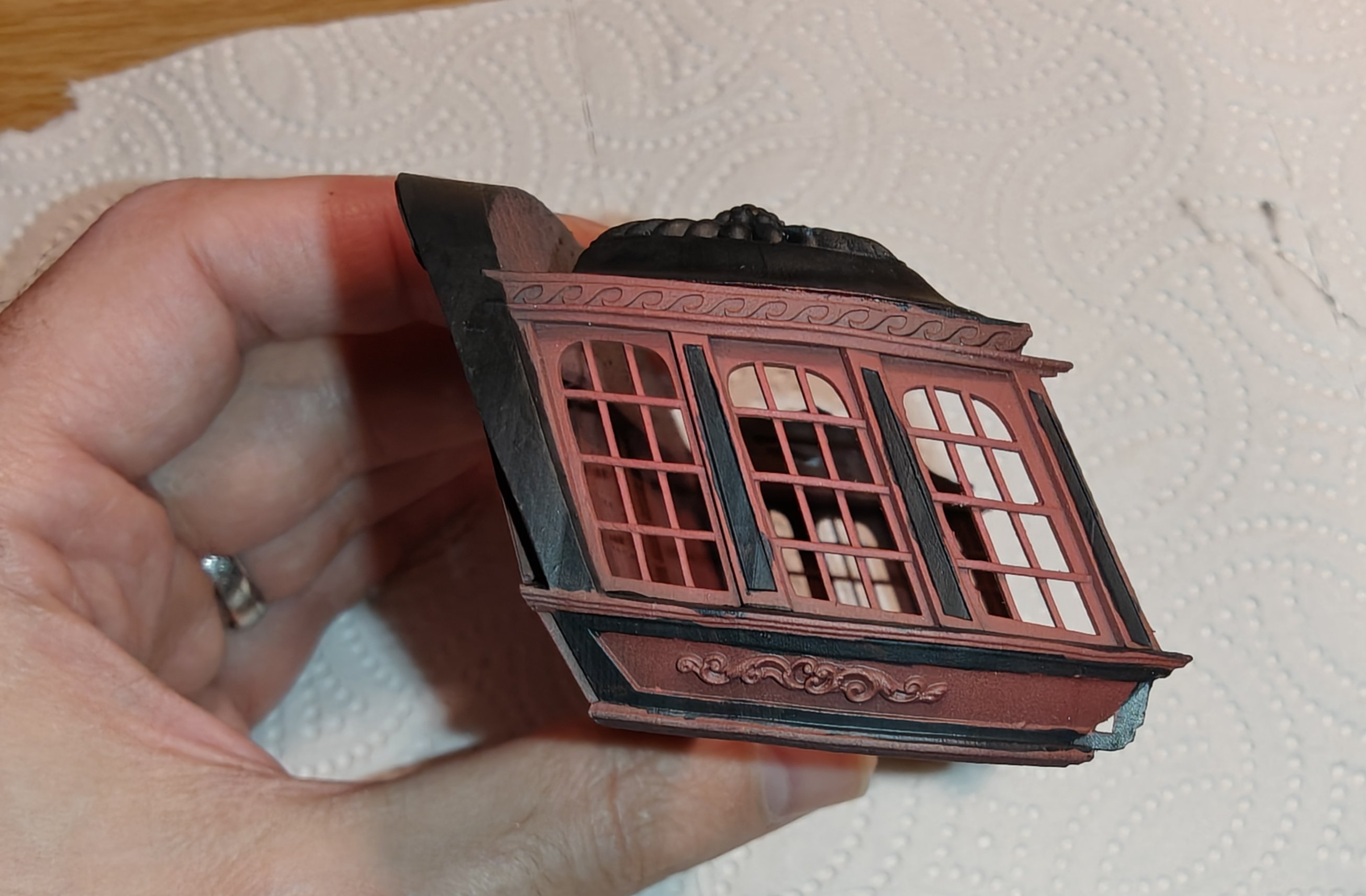
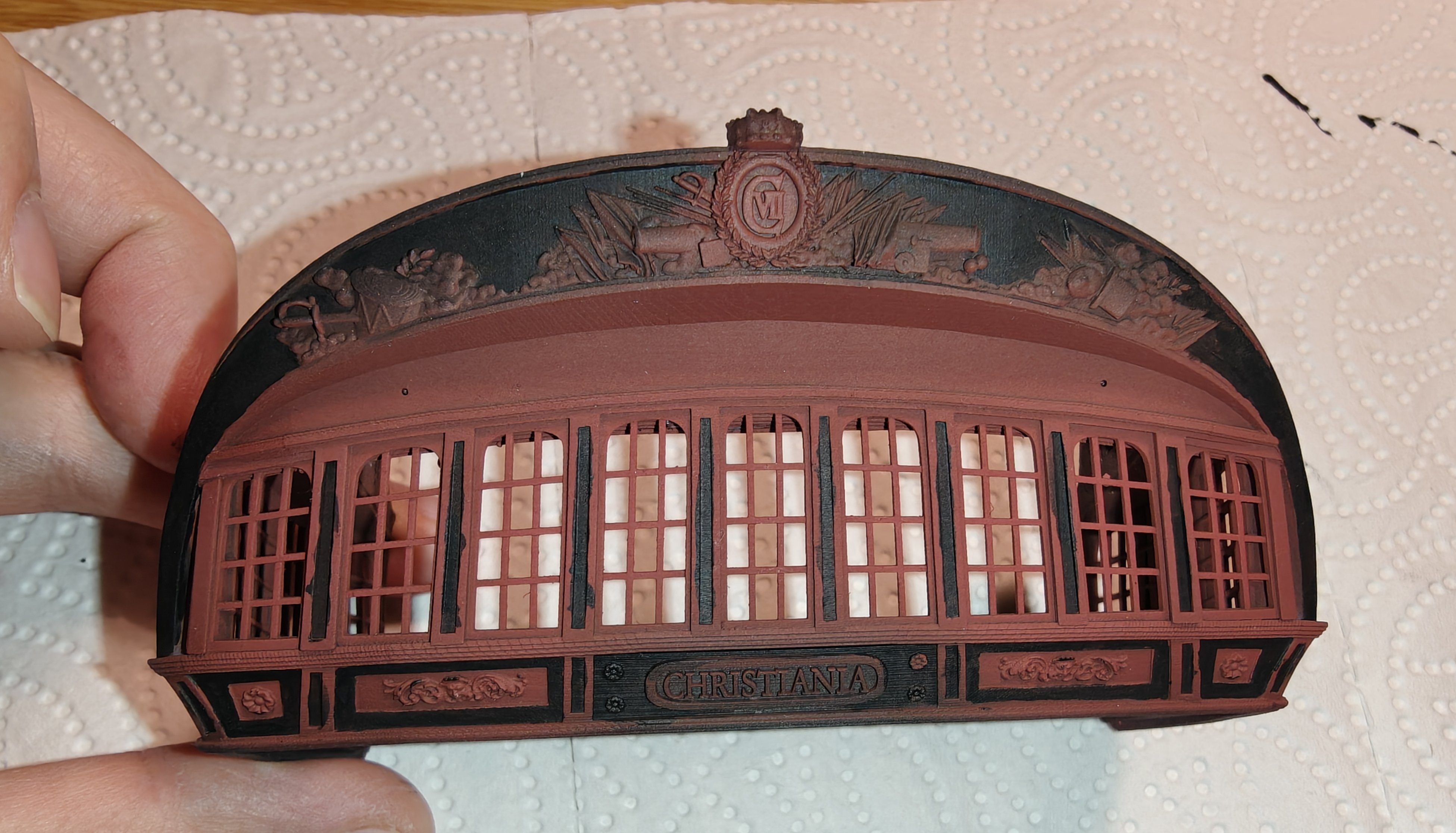
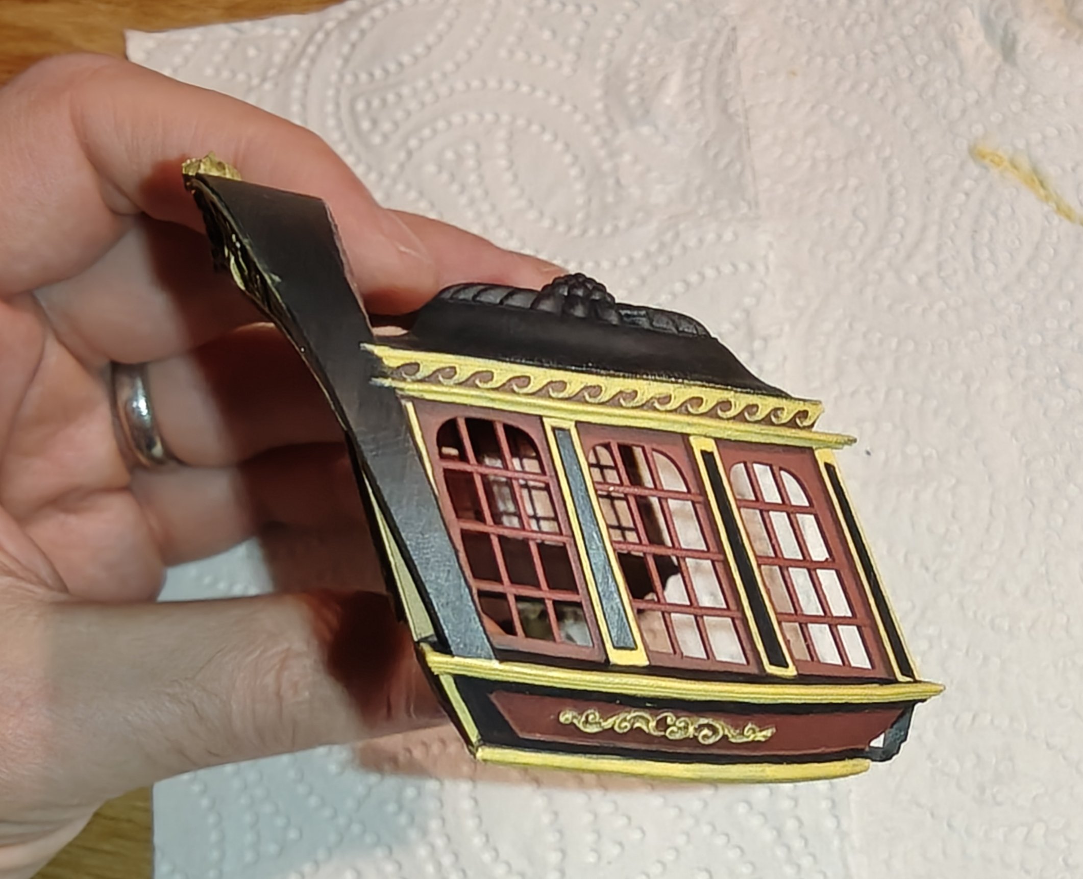
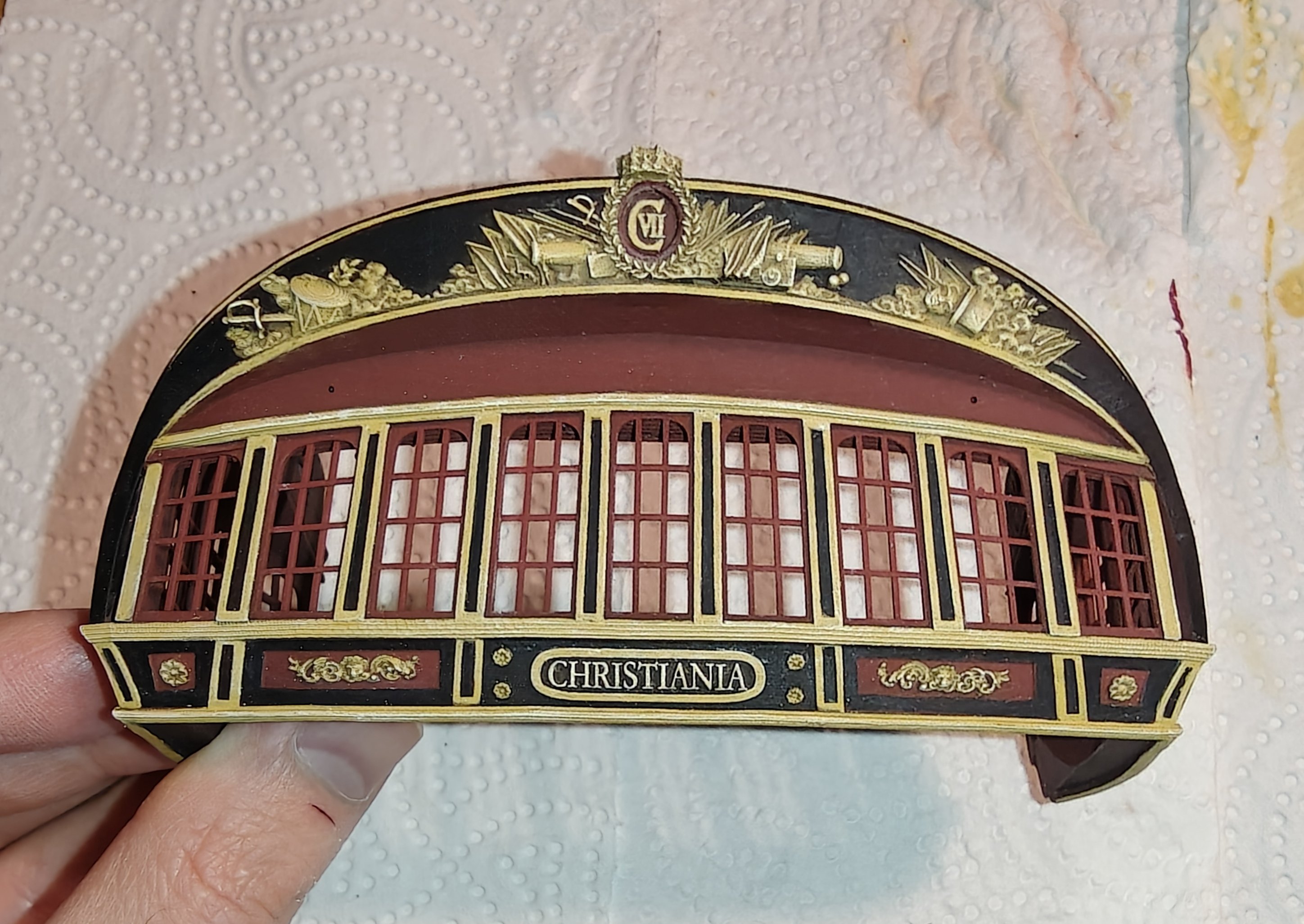
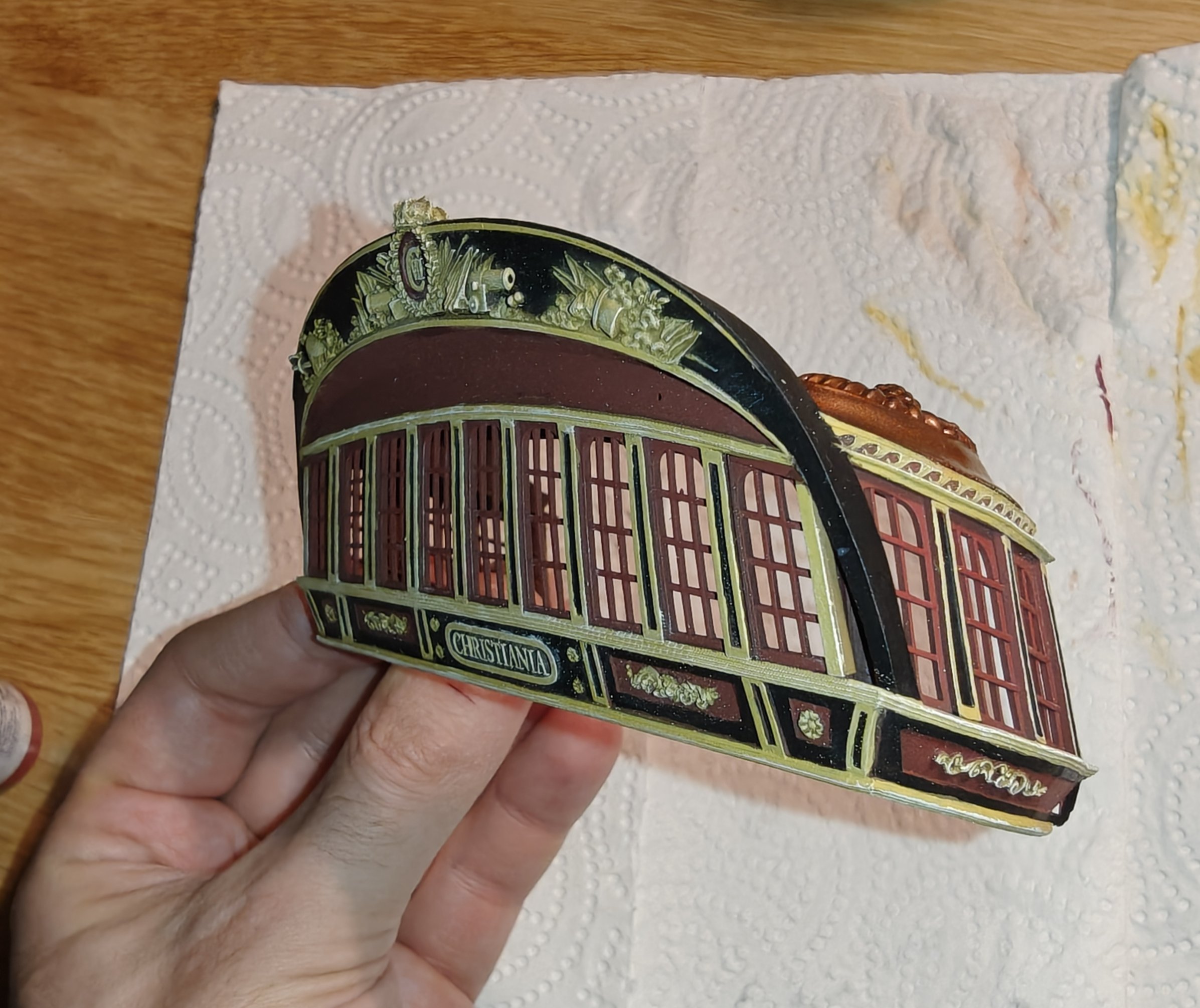
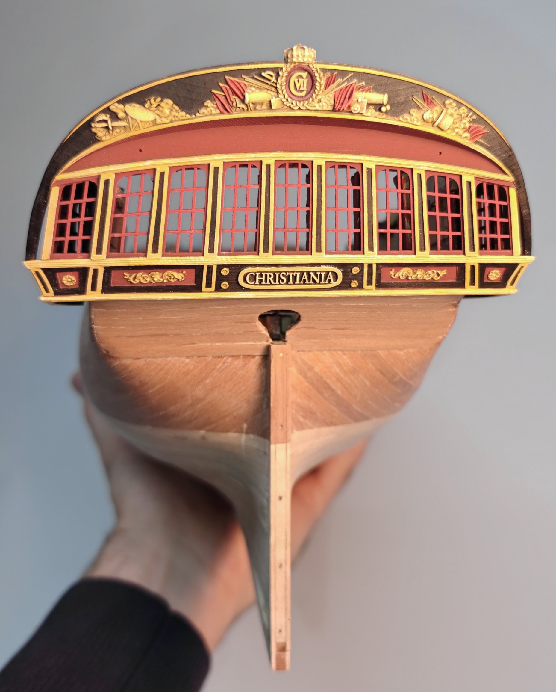
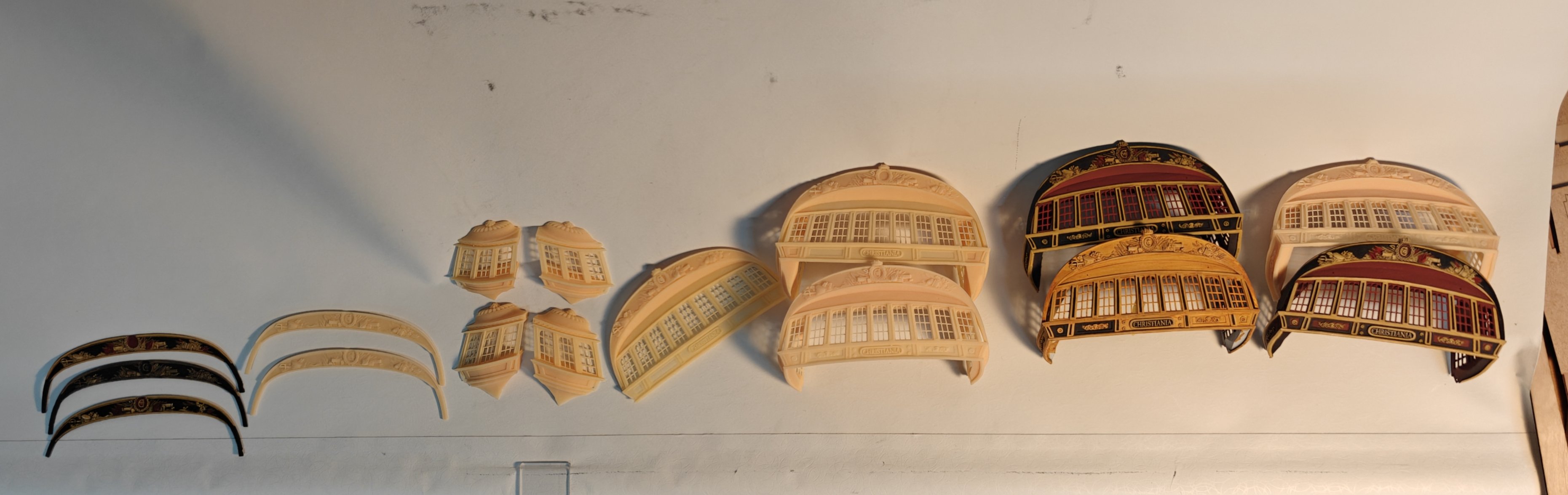
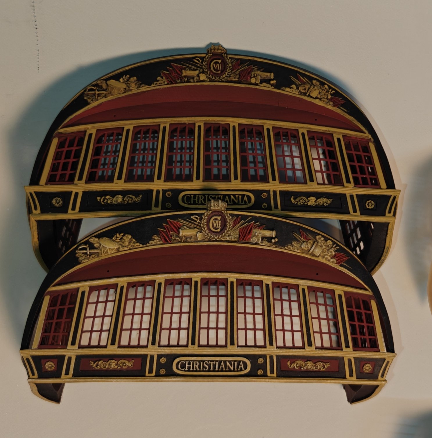
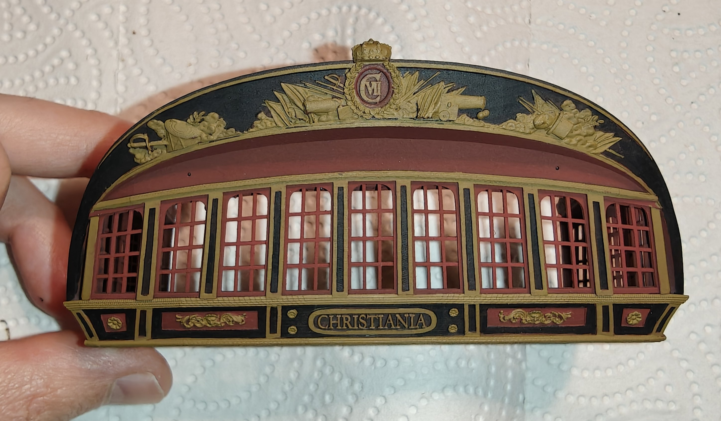
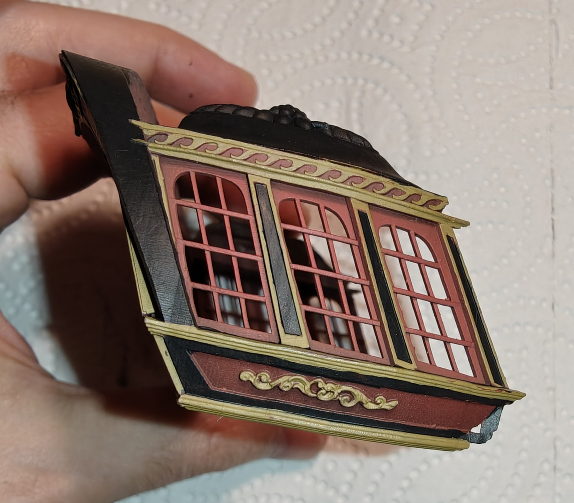
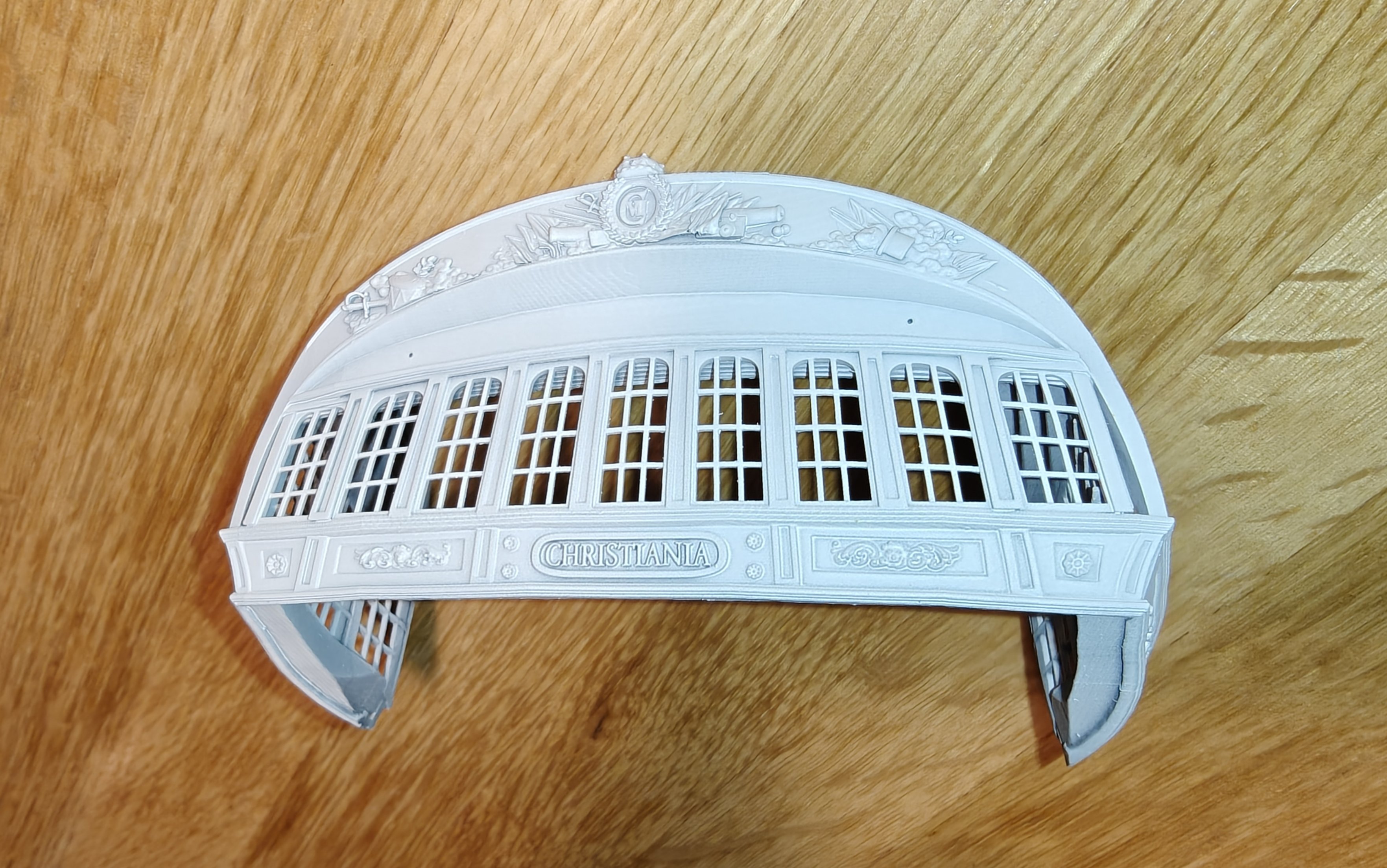
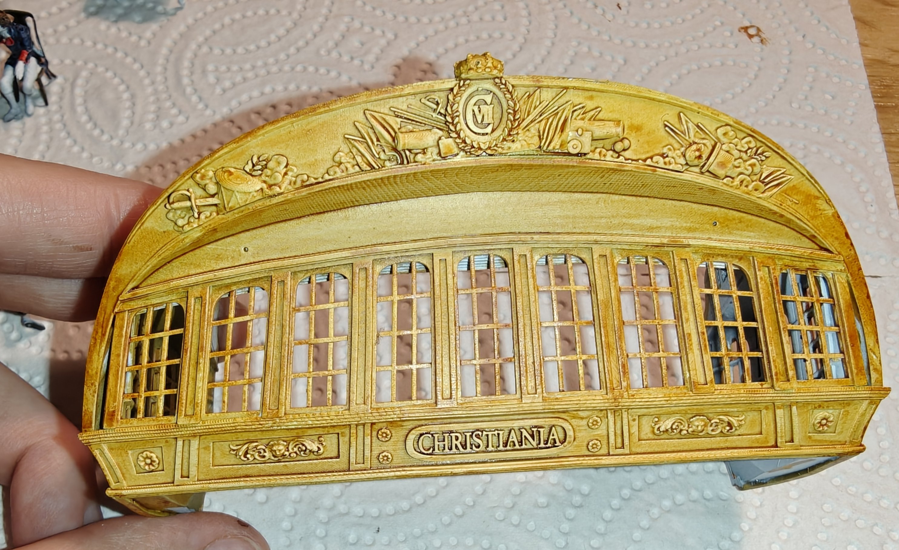
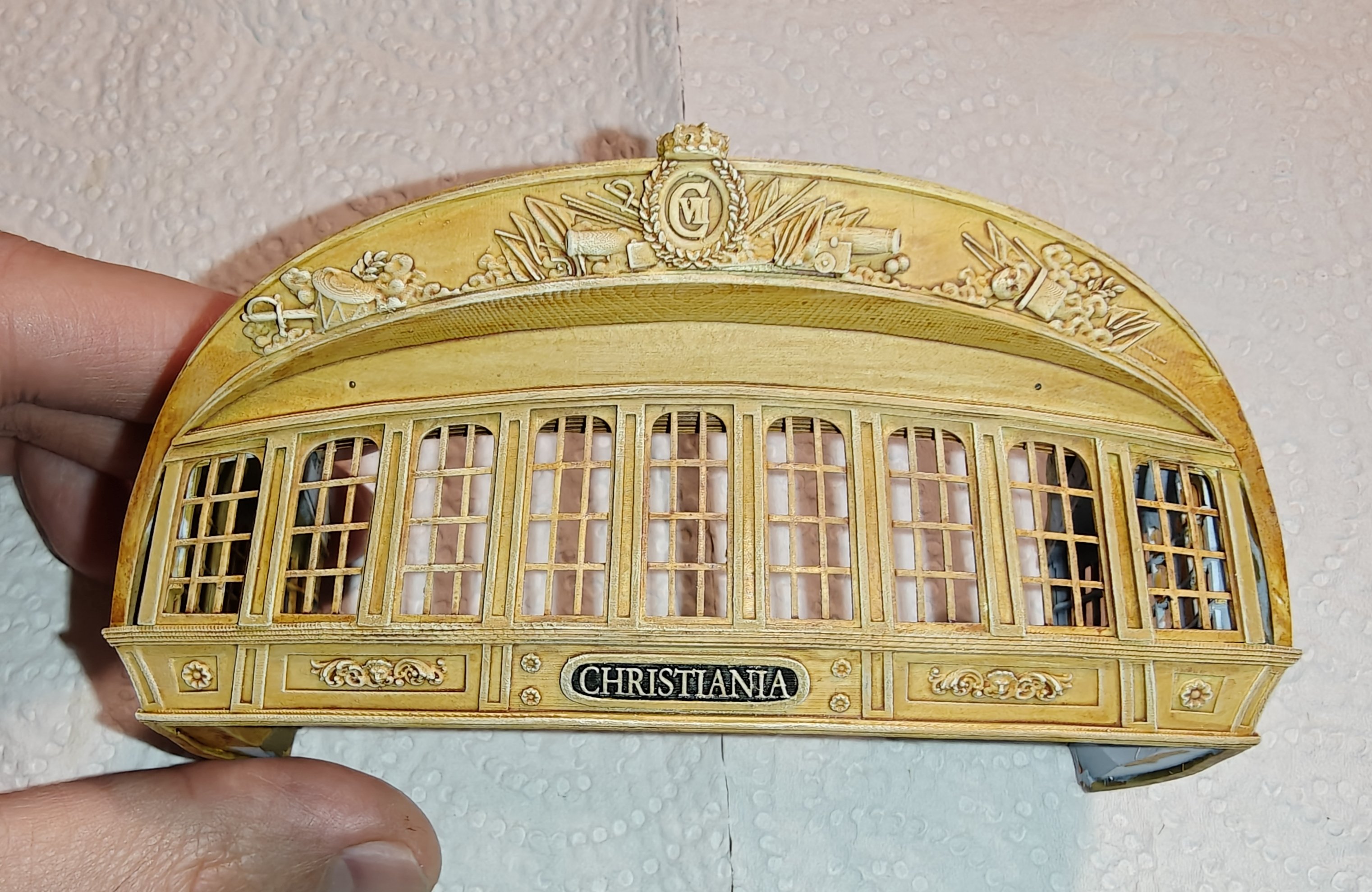
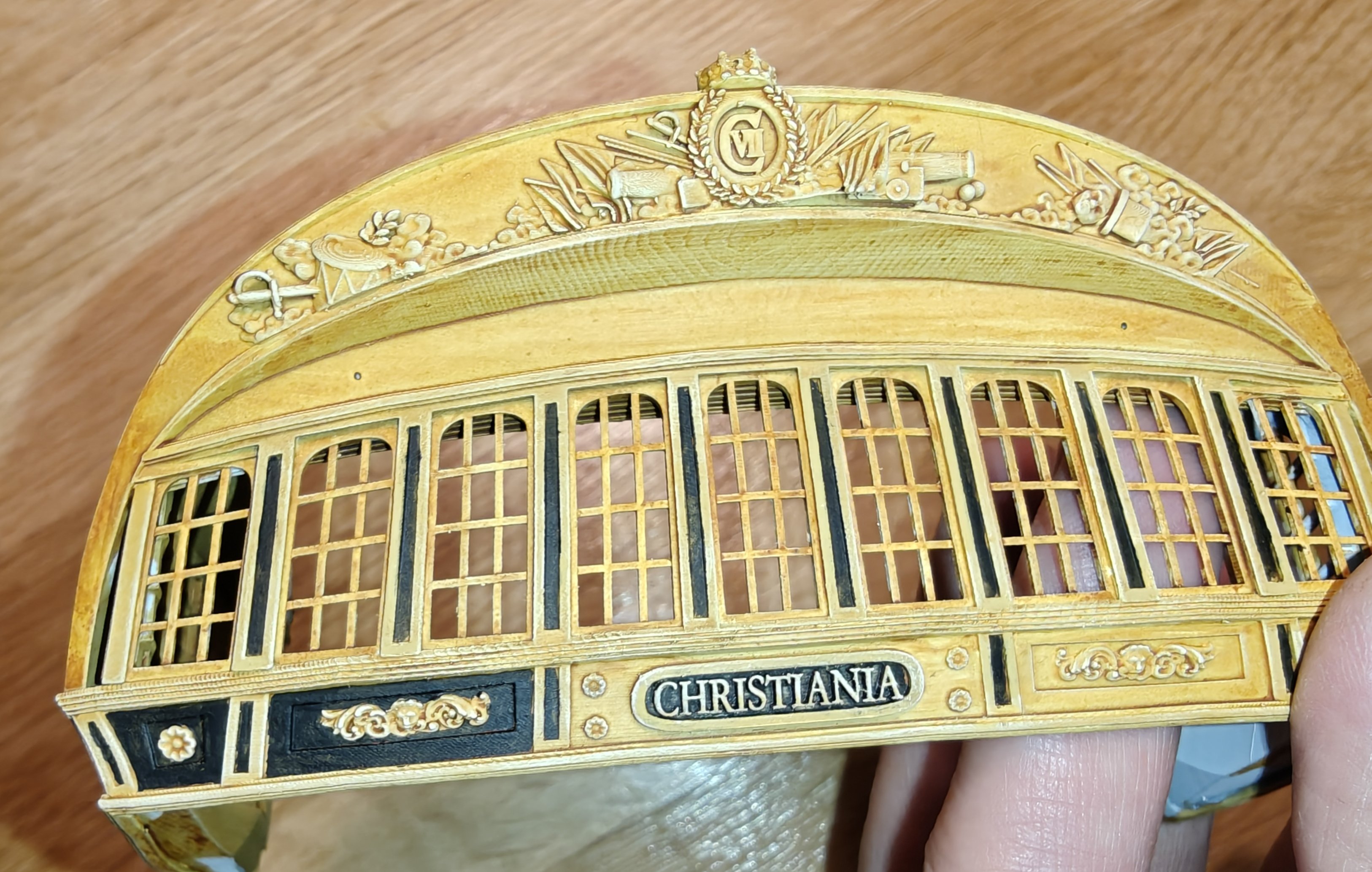
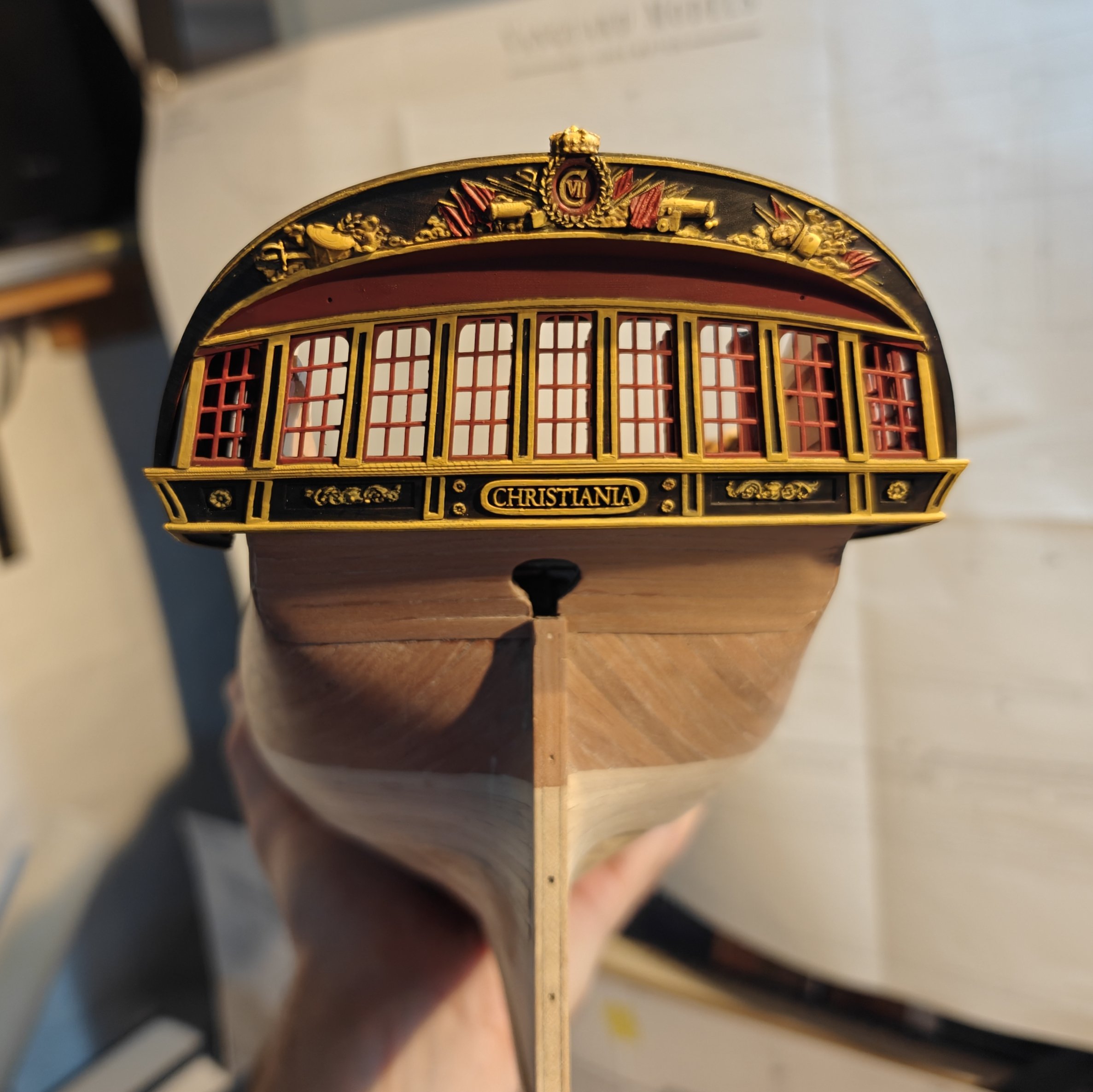
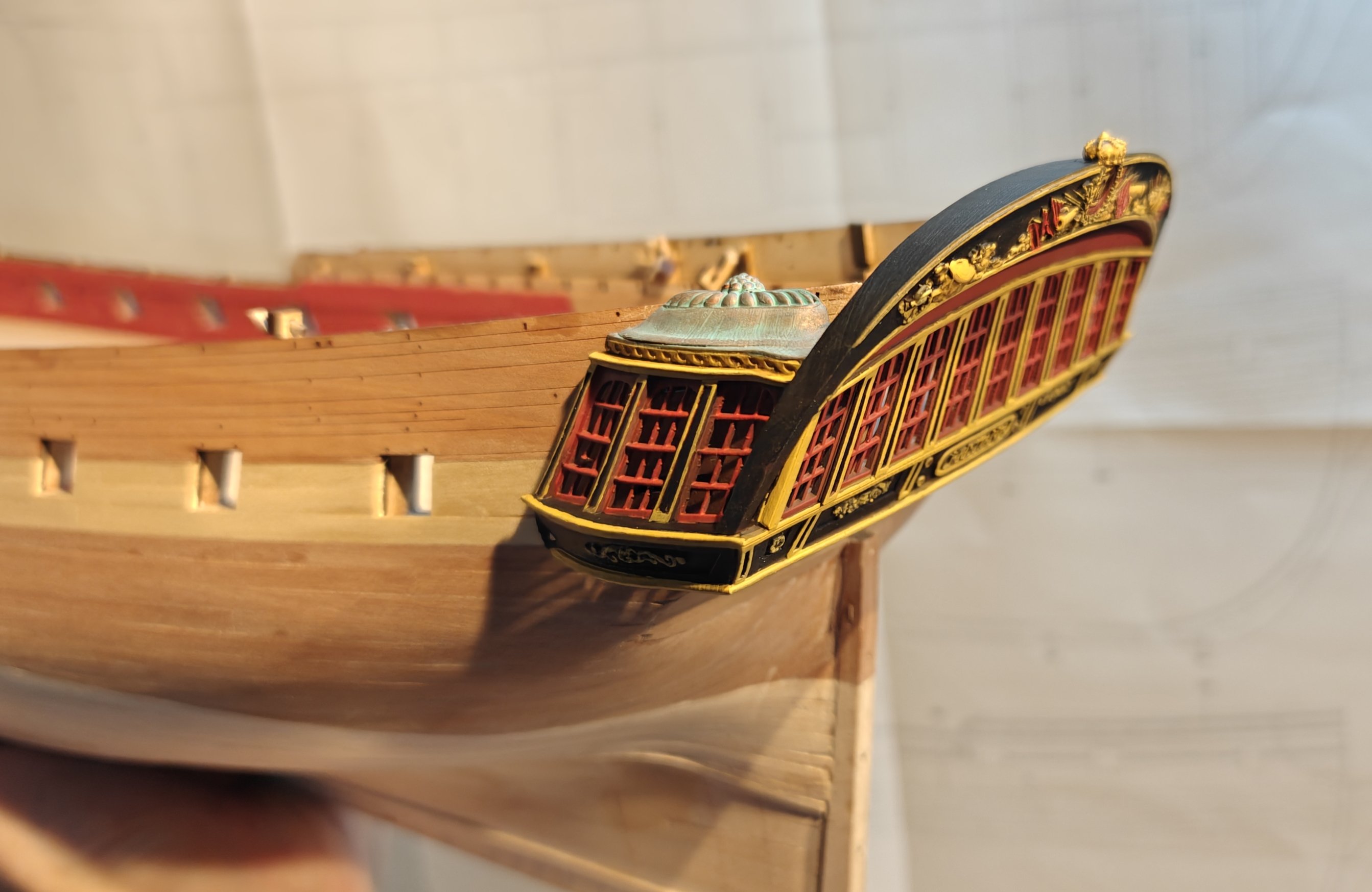
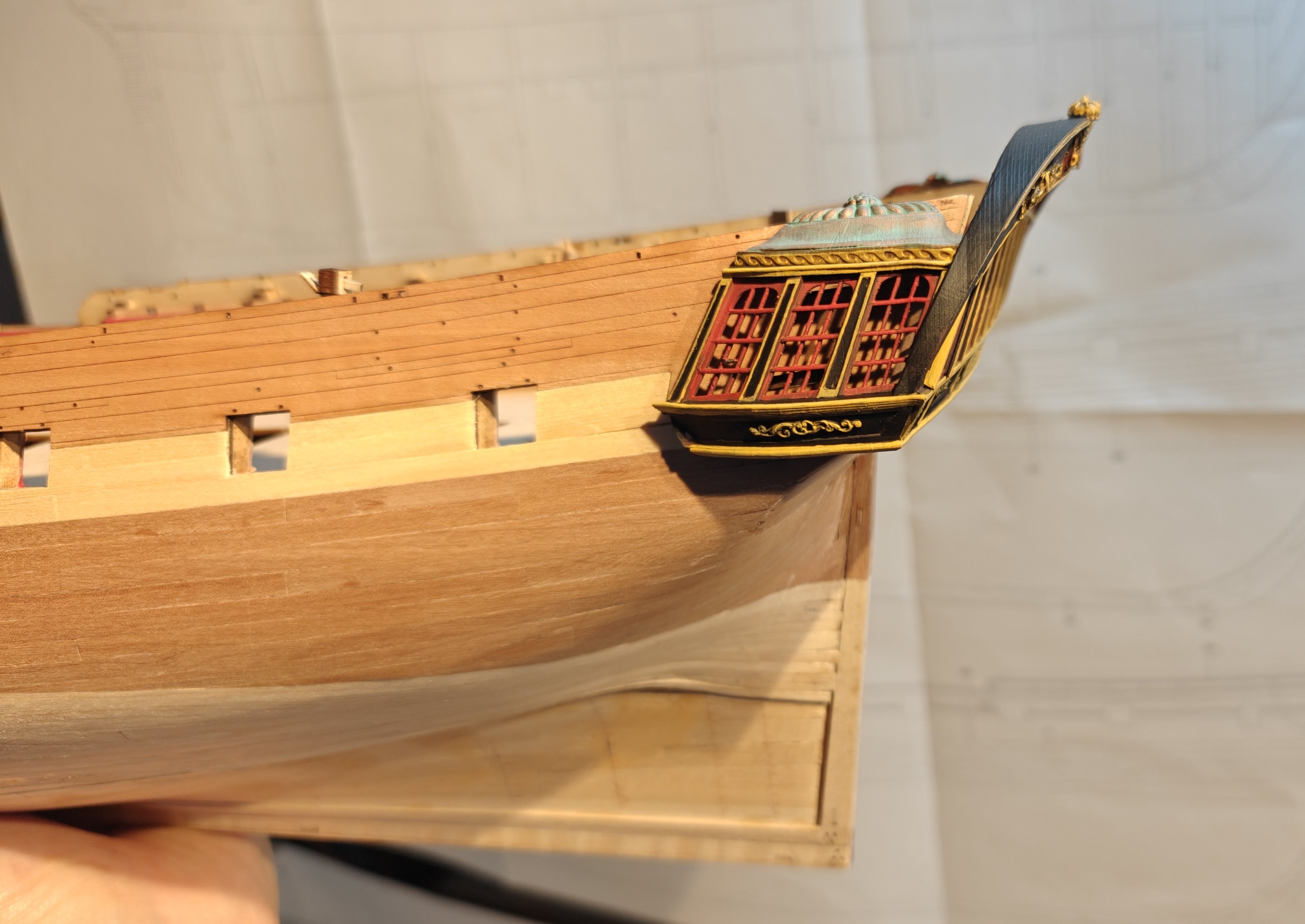
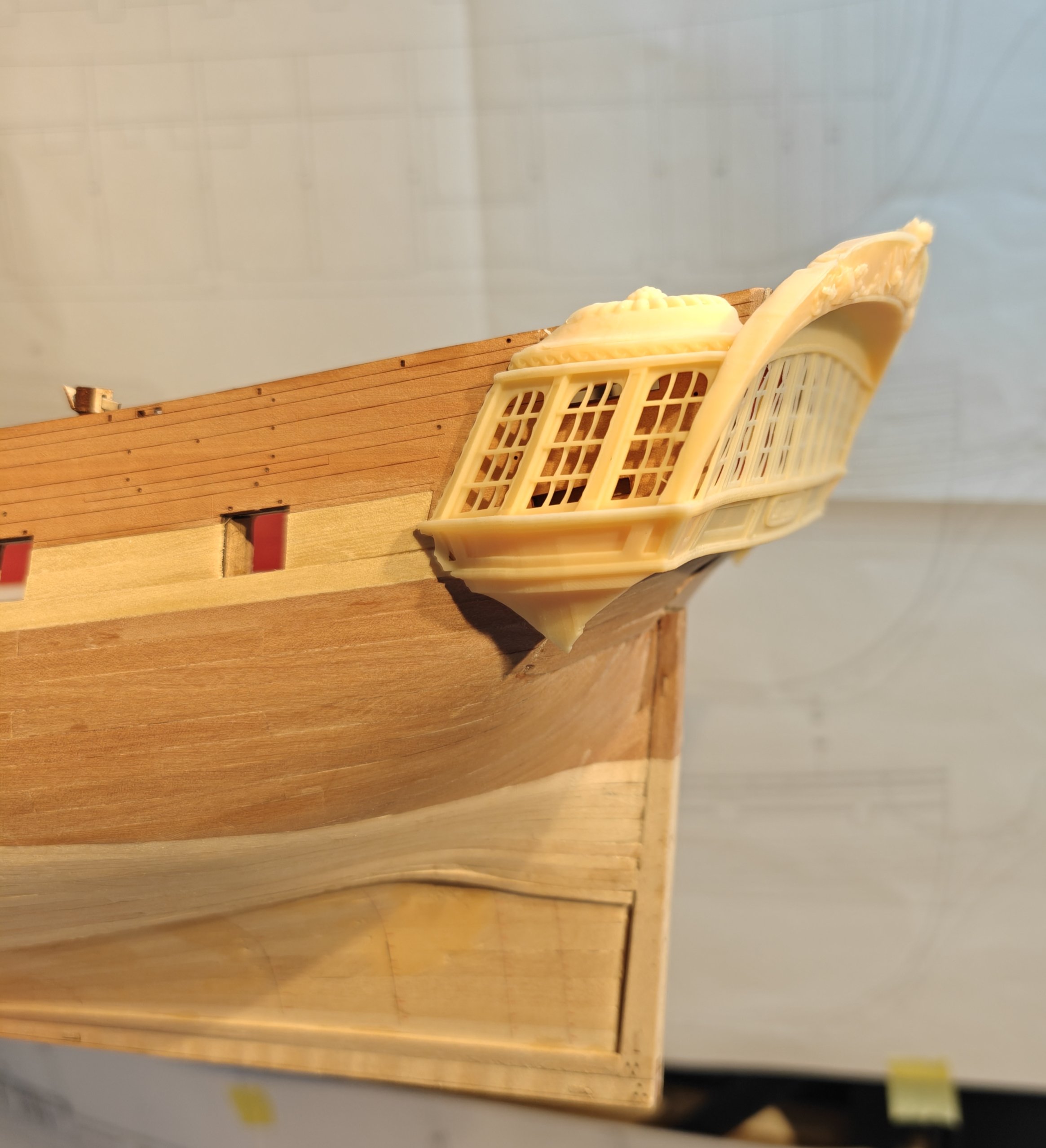
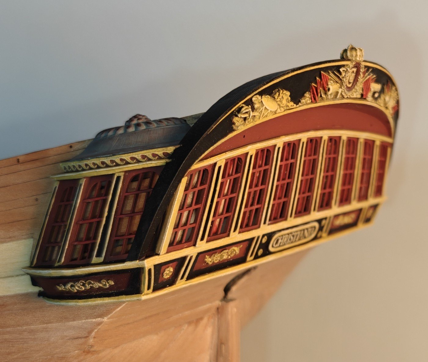
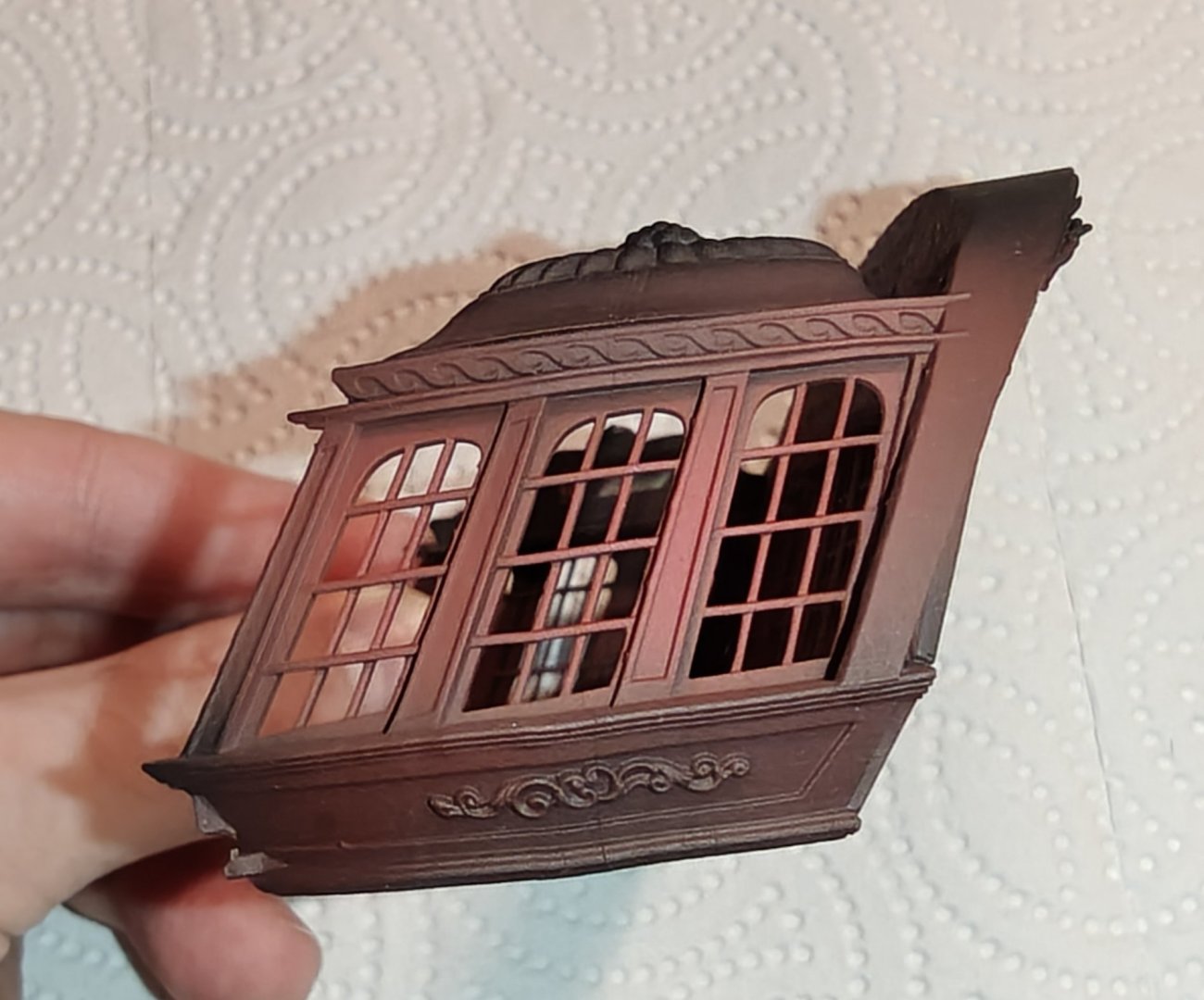
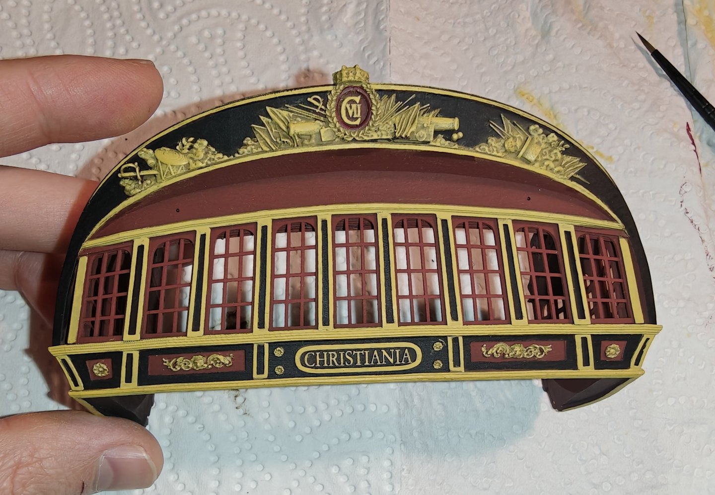
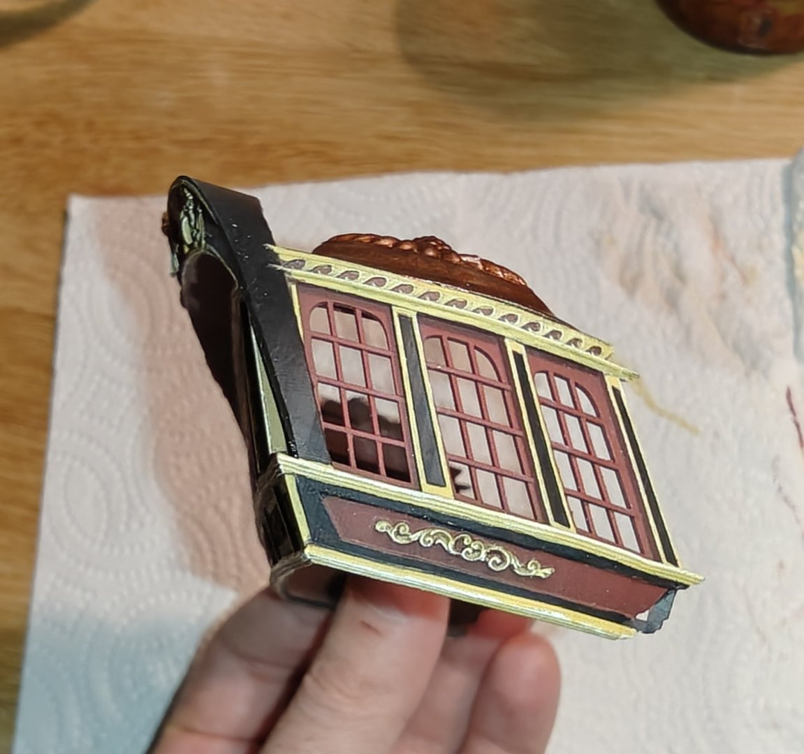
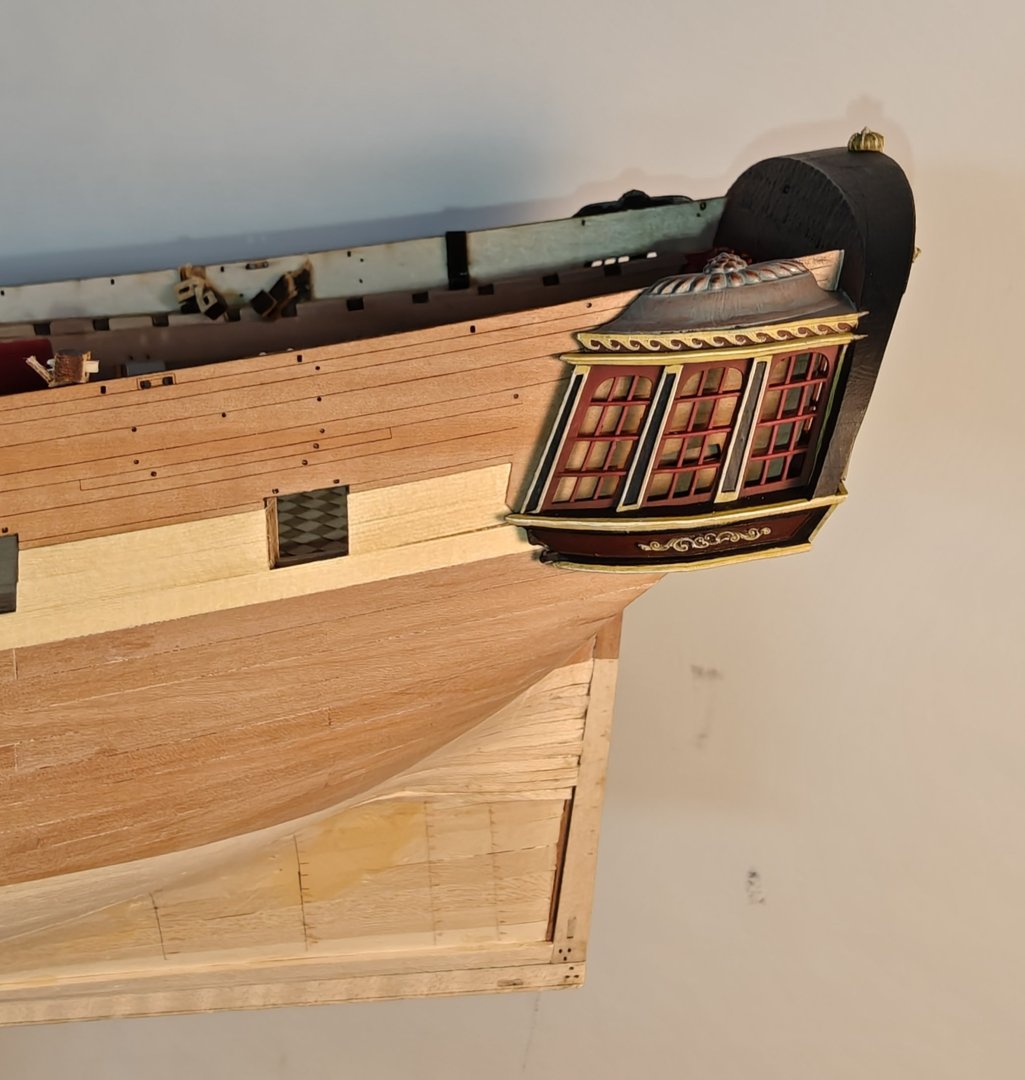
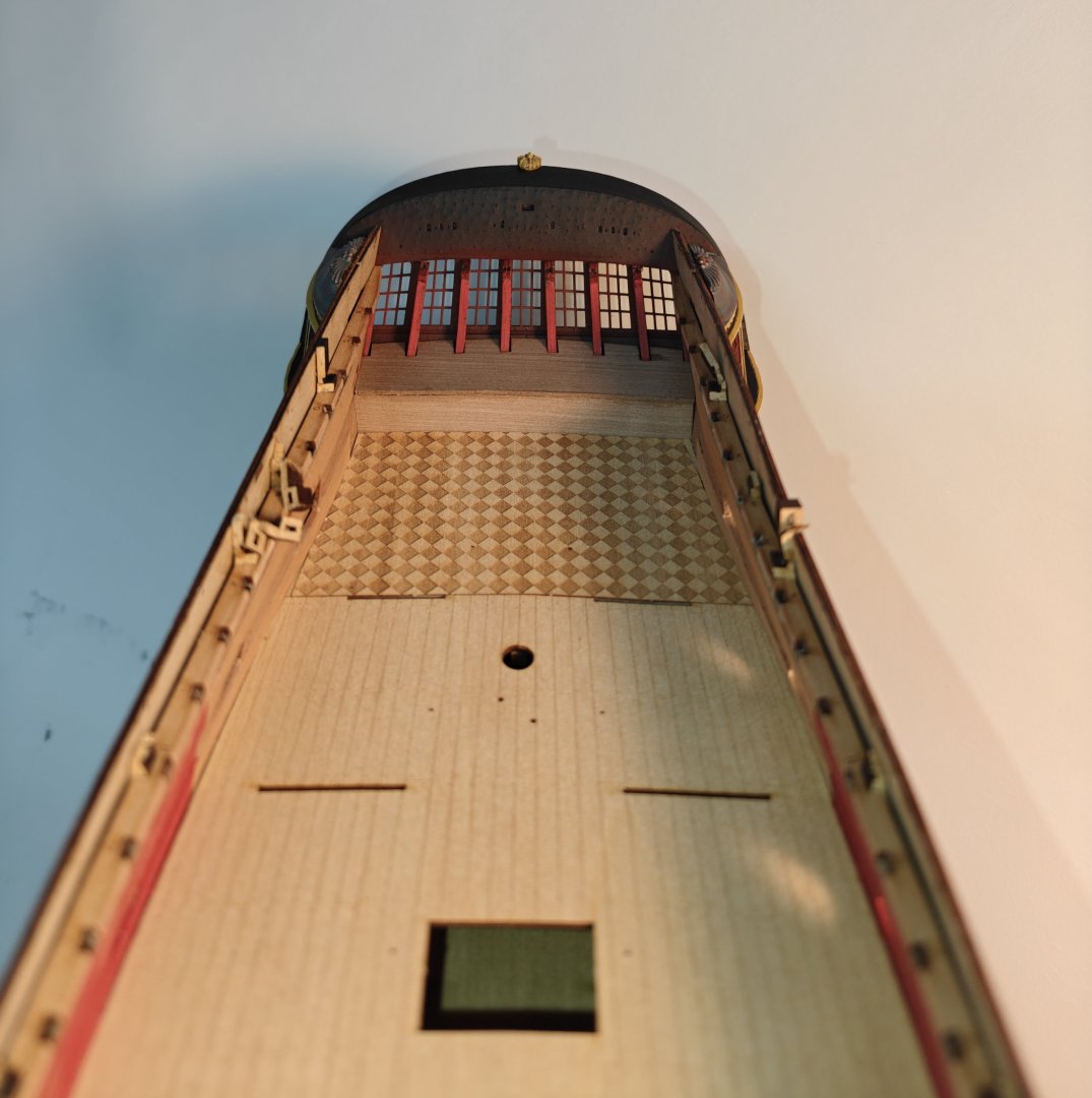
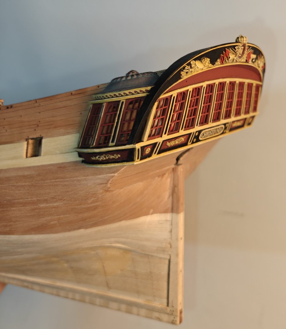
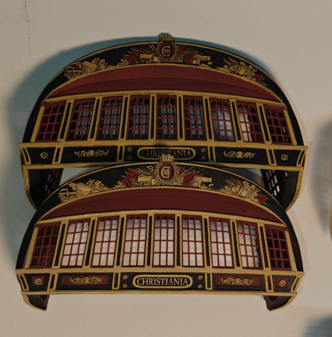
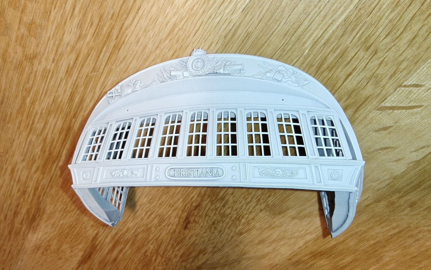
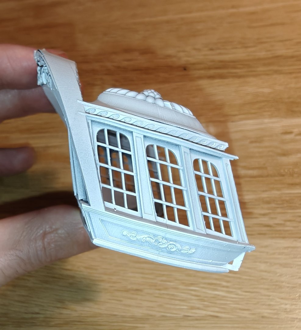
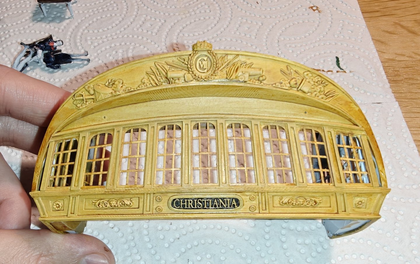
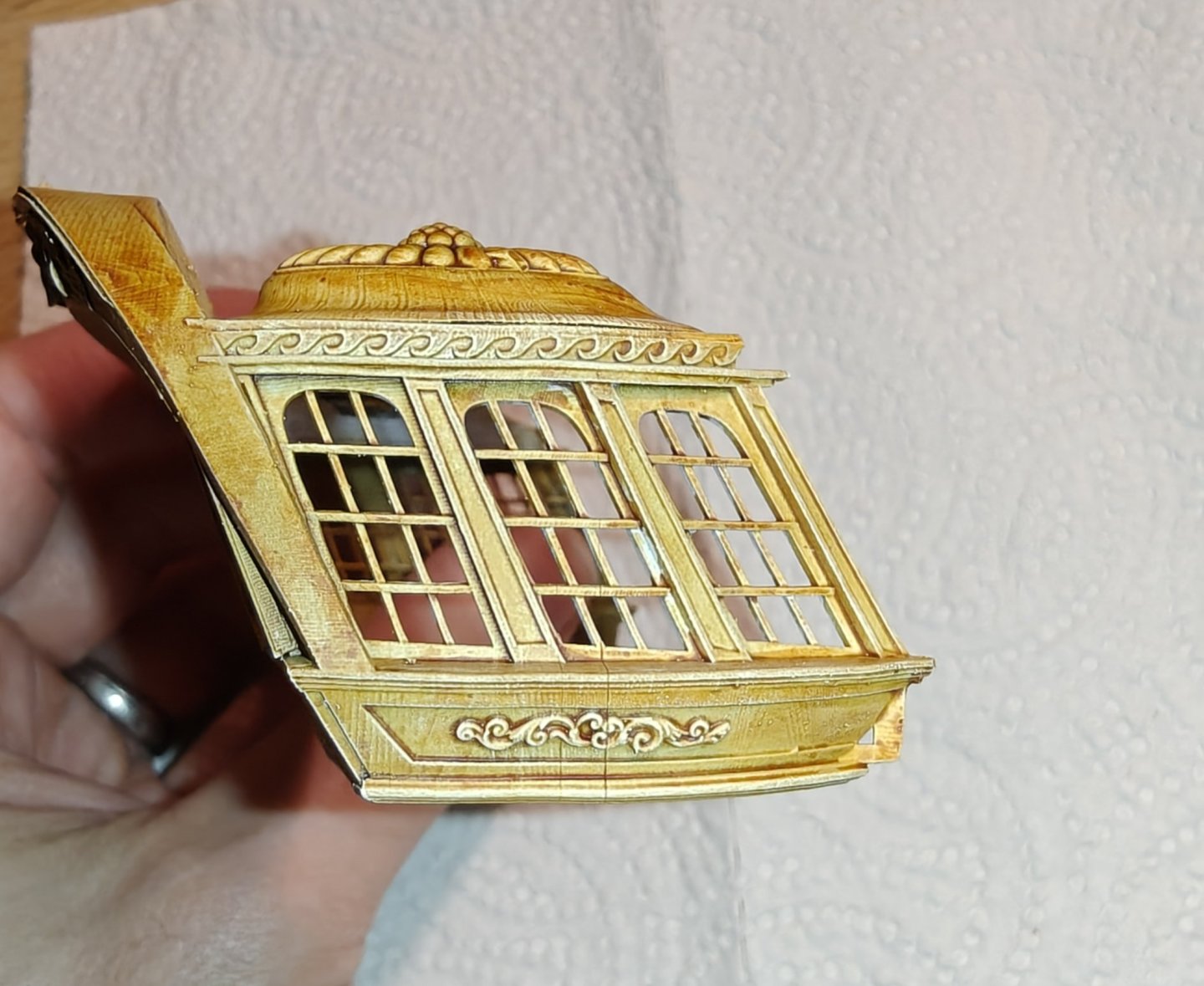
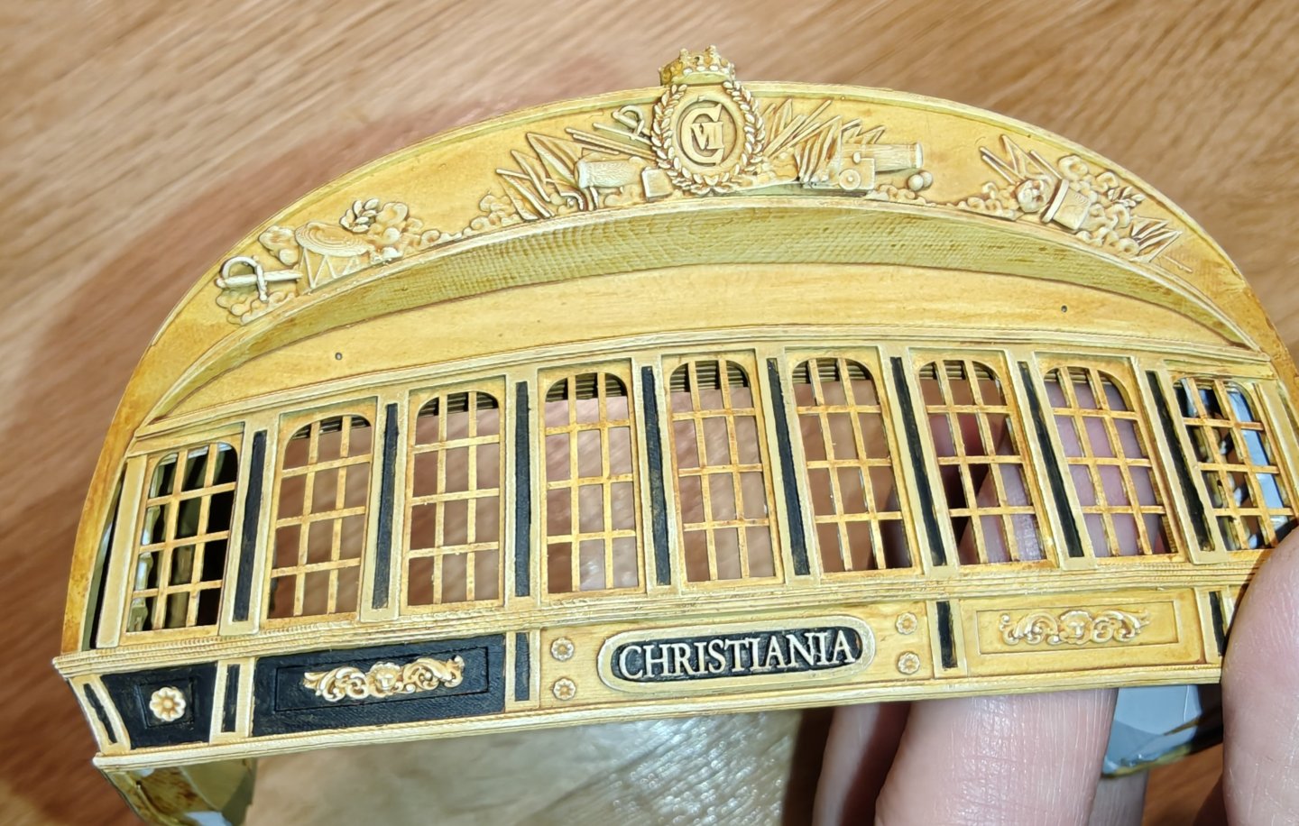
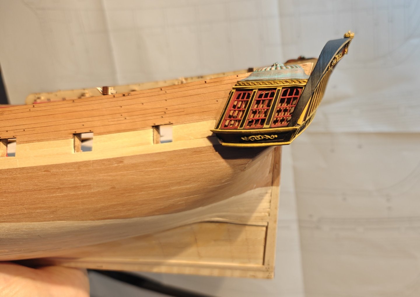
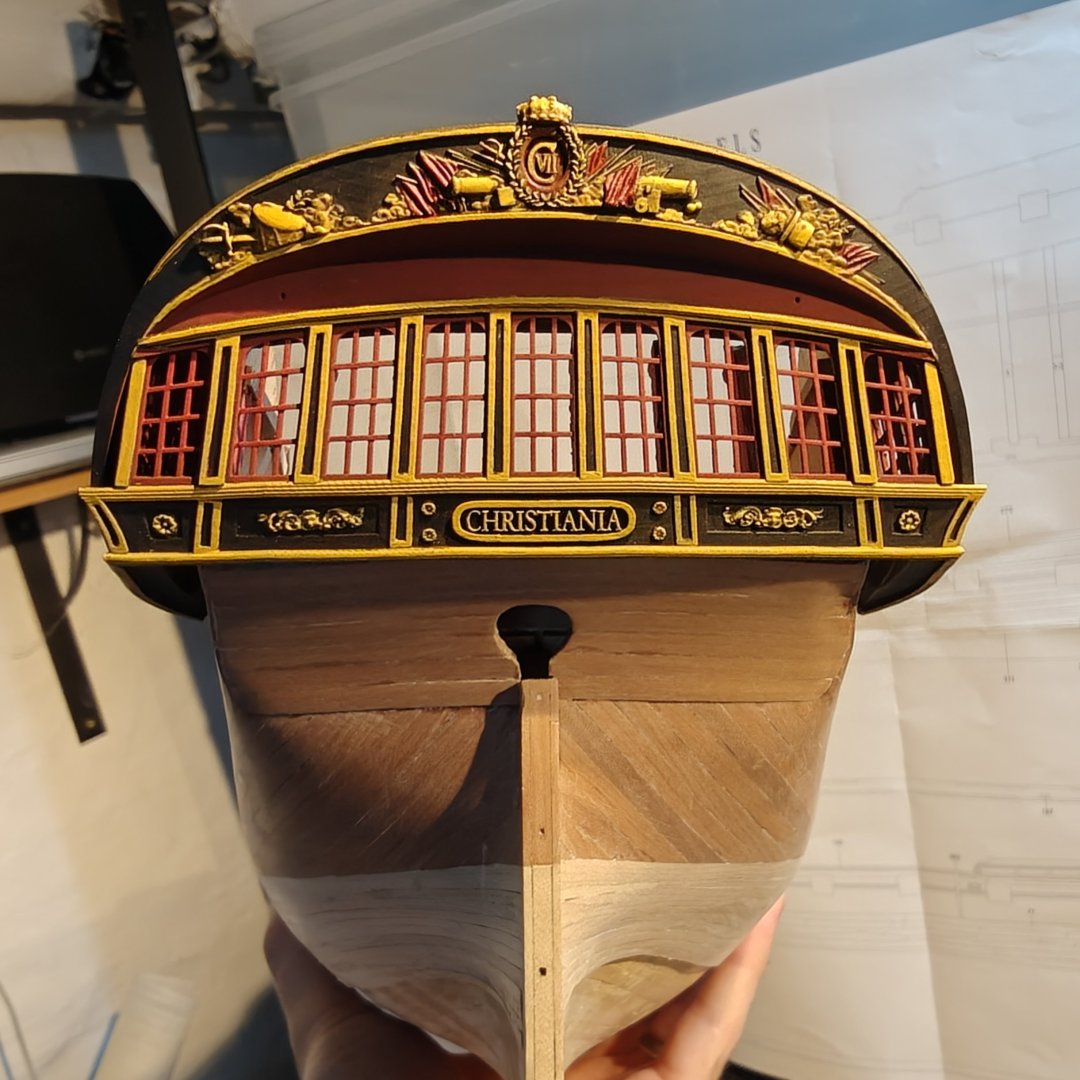
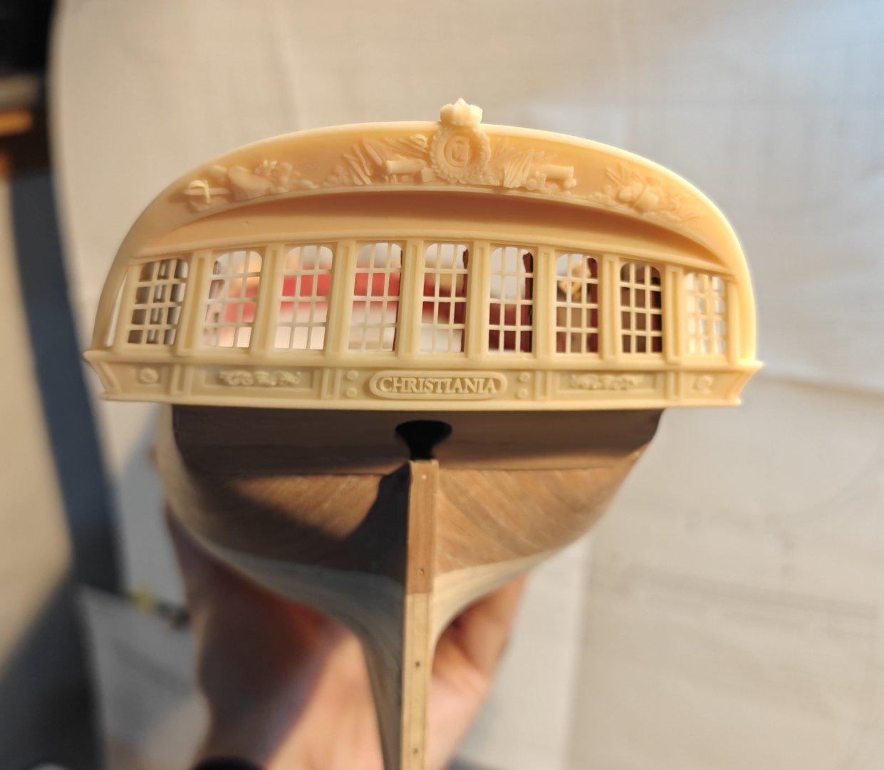
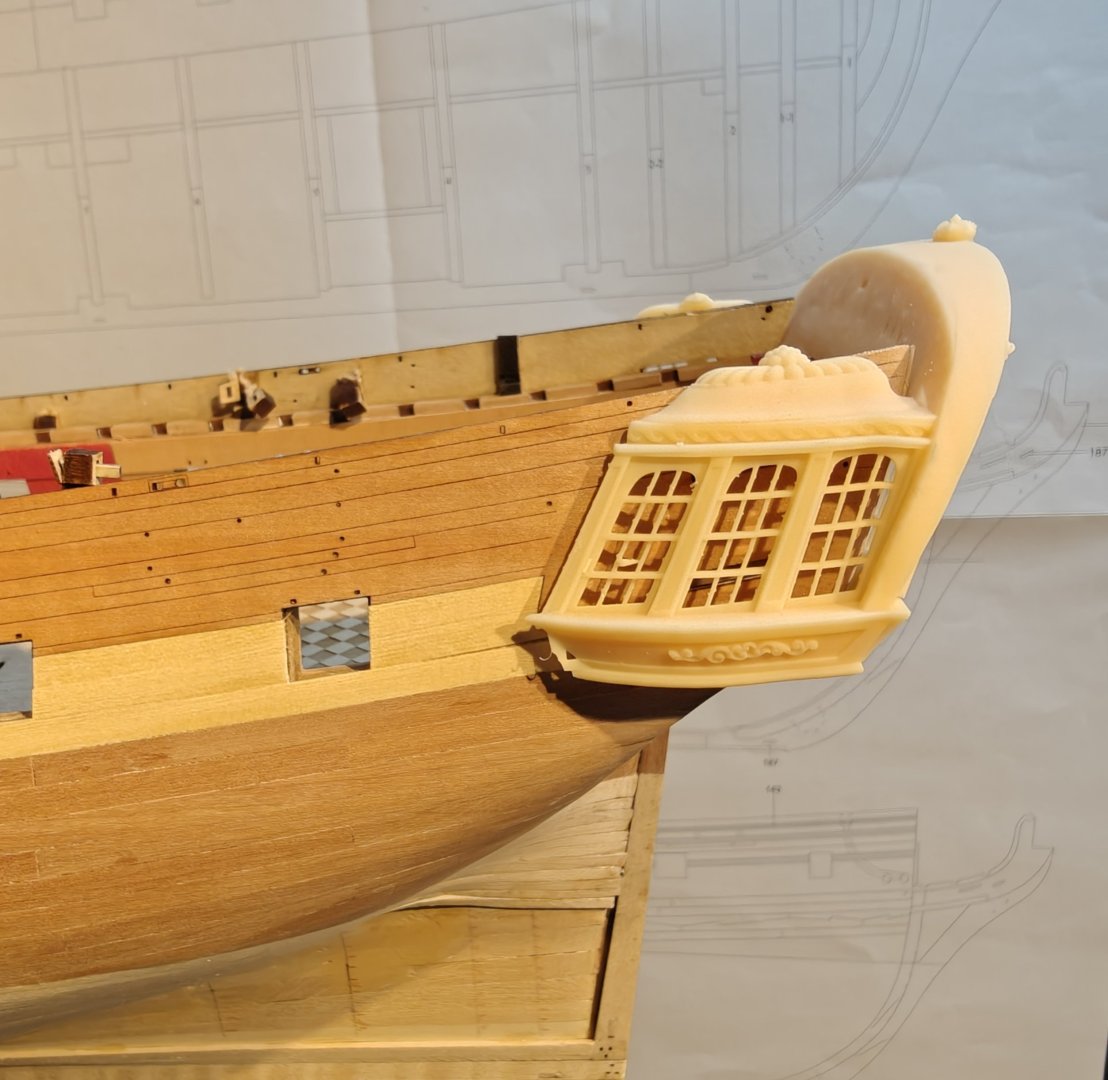
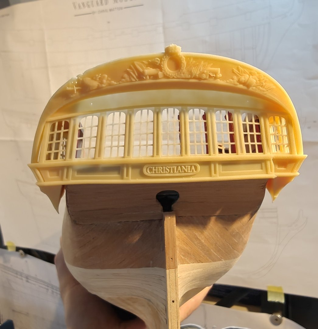
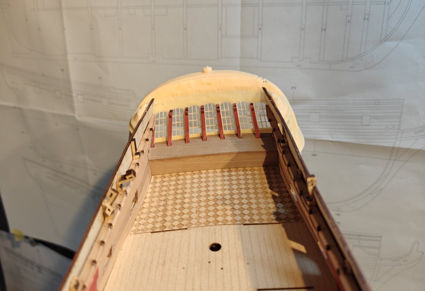
Log entry 32 - painting the stern decorations After some colour and technique tests earlier, I have now completed what I think will be the final version of the stern and side galleries. I will show the steps of the painting process, so sorry in advance for the large number of pictures in this post! 😅 After base coating the model black, I airbrushed the red window frames and the red panels. This was done with two shades of red over a couple of passes with the airbrush: After this, I went in and painted all the black parts, taking care not to mess up the red parts - it is almost impossible to touch up on the airbrushed red without it showing! Then the yellow parts were base coated with brown - this took forever as I had to move very, very slowly: So far so good! Then comes tje most difficult job, which is to do the yellow. It takes even longer than the brown as it needs 2-3 coats. The friese and other 3D decorations are drybrushed on. The last step is highlights with beige, using drybrushing. Phew! Just missing the red flags. Here is a comparison with my colour test from a few weeks ago. And finally som images with the part on the ship (just dry fitted as I need to figure out what to do with the window glass and finish the planking before it is attached permanently). This is the best I can do painting wise I think, and I think it will look good in the end. The camera picks up all the harsh colour transitions, but it looks smoother in real life. And just a fun shot here at the end of all the different iterations I have gone through... 🫣 I am happy to have this done - it was by far the most difficult kit-bashing for this project, so having completed it, the rest of the build should be much more straight sailing, following the manual! BR TJM


- 148 replies
-
- 18
-

-
-
- Christiania
- Vanguard Models
- (and 1 more)
-
Probably not too much, unfortunately. Acc. to 'Den historiske modelsamling på Holmen', by P. Holck from 1939, the masts and rig suffered considerable damage in the 1795 fire. It was supposedly meticulously restored afterwards.
-
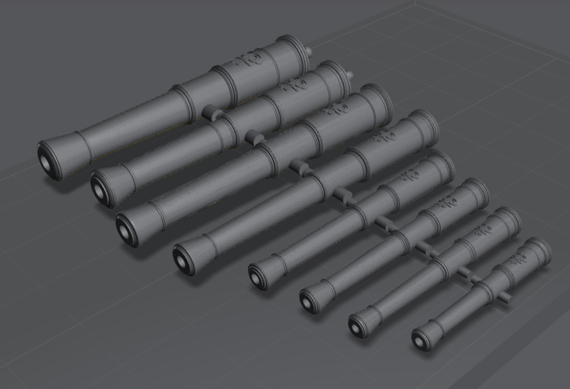
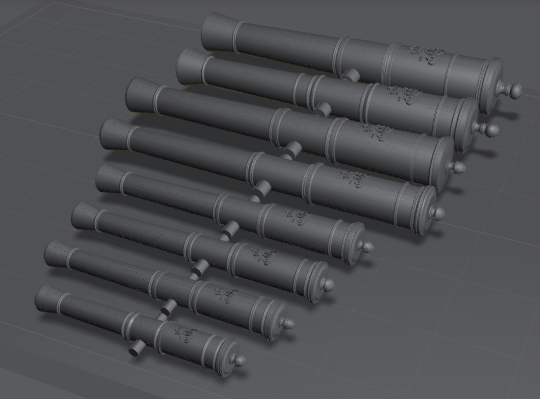
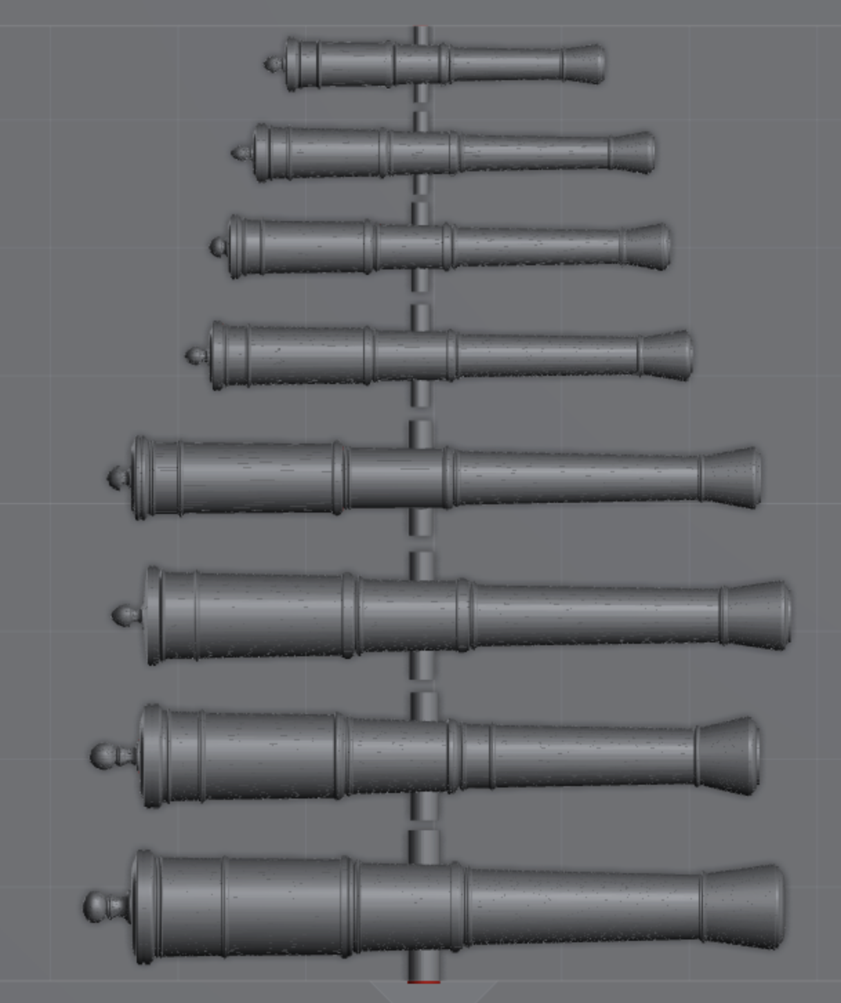
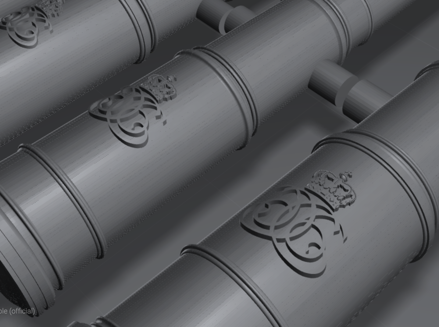
3 pounder - C6 monogram: 3 pund C6.stl 4 pounder - C6 monogram: 4 pund C6.stl 6 pounder - C6 monogram: 6 pund C6.stl 8 pounder - C6 monogram: 8 pund C6.stl 12 pounder - C6 monogram: 12 pund C6.stl 18 pounder - C6 monogram: 18 pund C6.stl 24 pounder - C6 monogram: 24 pund C6.stl 36 pounder - C6 monogram: 36 pund C6.stl 42 pounder - C6 monogram: 42 pund C6.stl
-
3 pounder - no monogram: 3 pund.stl 4 pounder - no monogram: 4 pund.stl 6 pounder - no monogram: 6 pund.stl 8 pounder - no monogram: 8 pund.stl 12 pounder - no monogram: 12 pund.stl 18 pounder - no monogram: 18 pund.stl 24 pounder - no monogram: 24 pund.stl 36 pounder - no monogram: 36 pund.stl 42 pounder - no monogram: 42 pund.stl
-
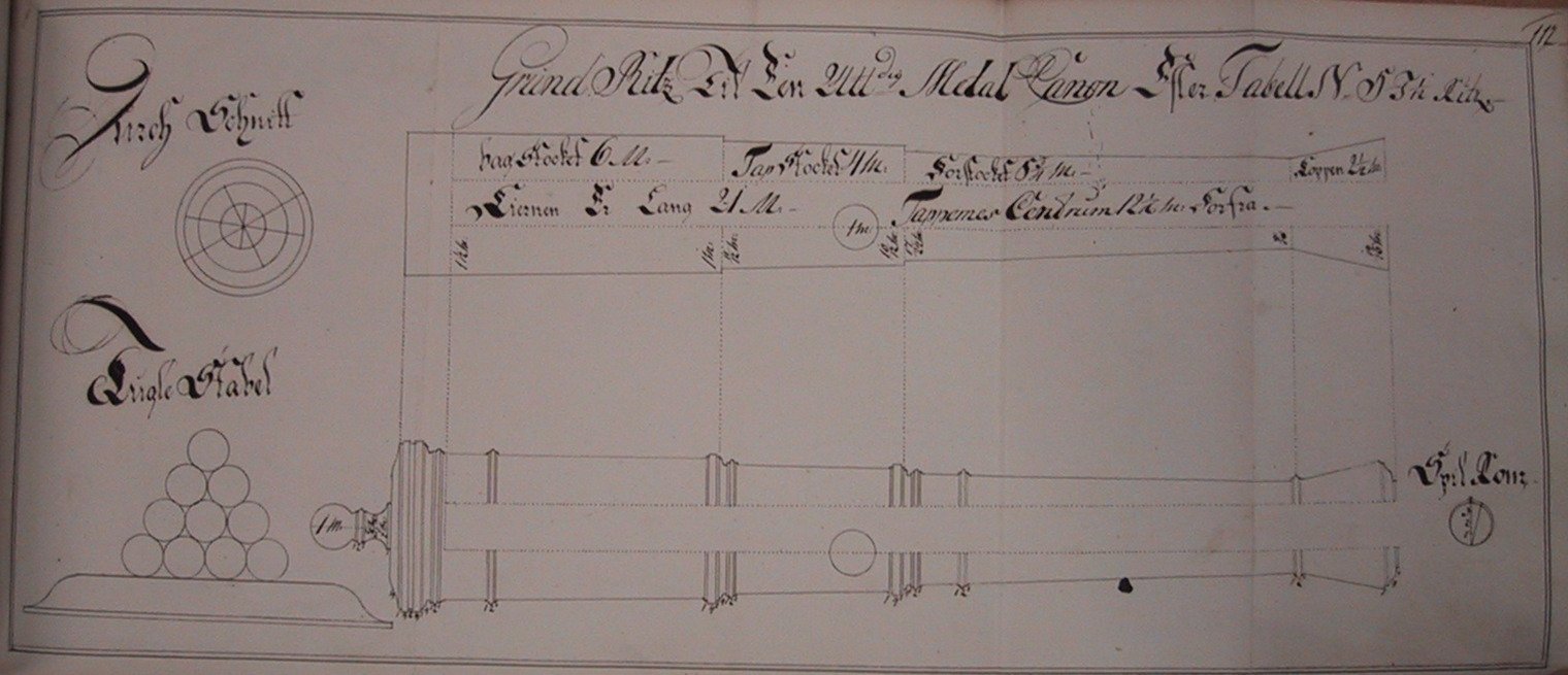
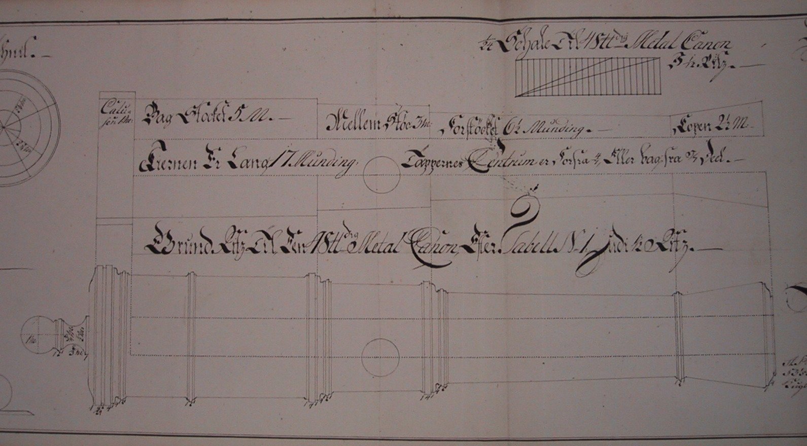
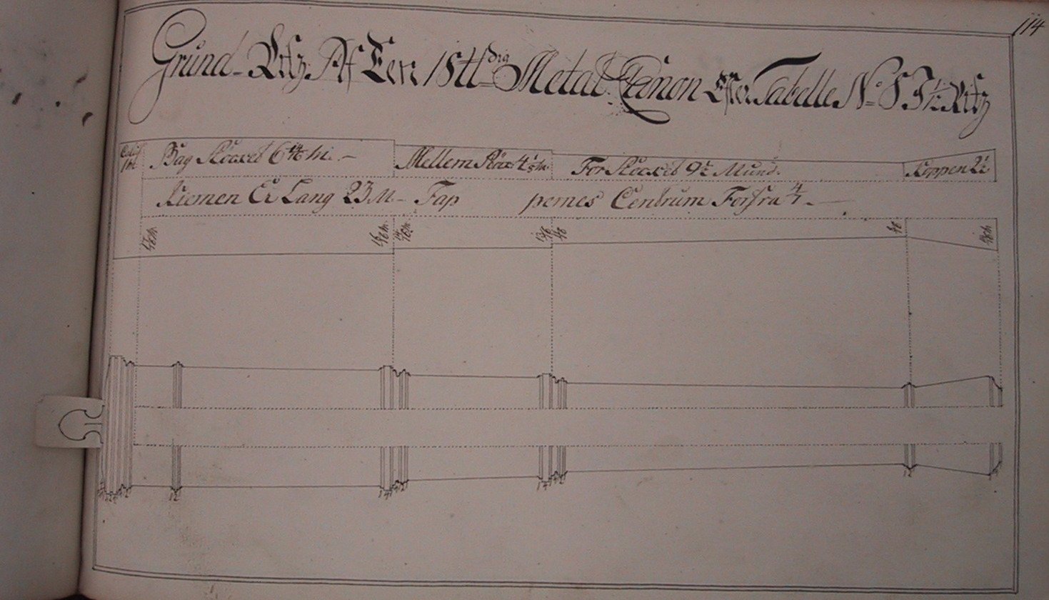
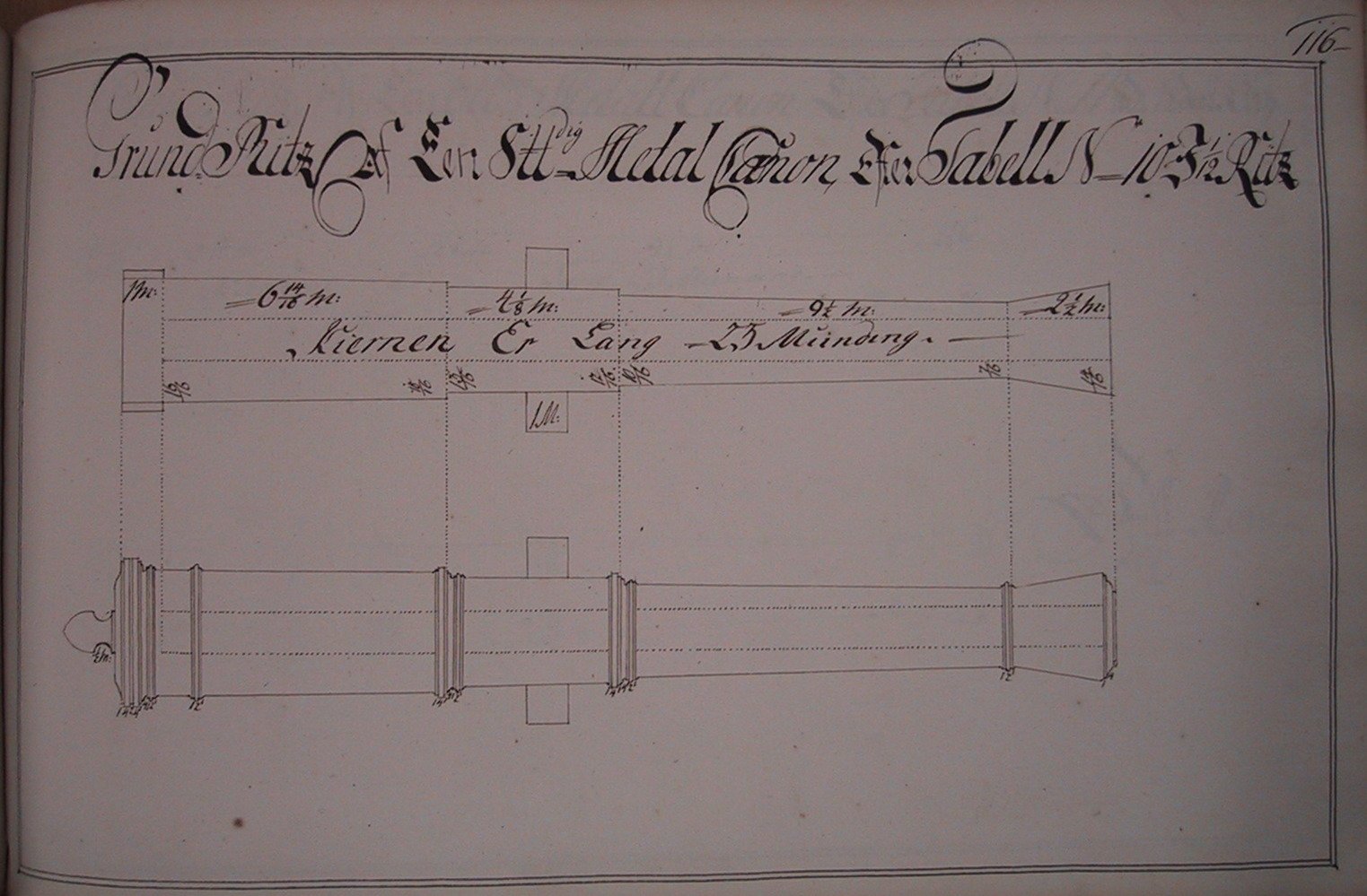
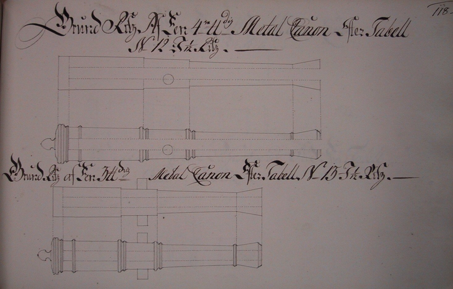
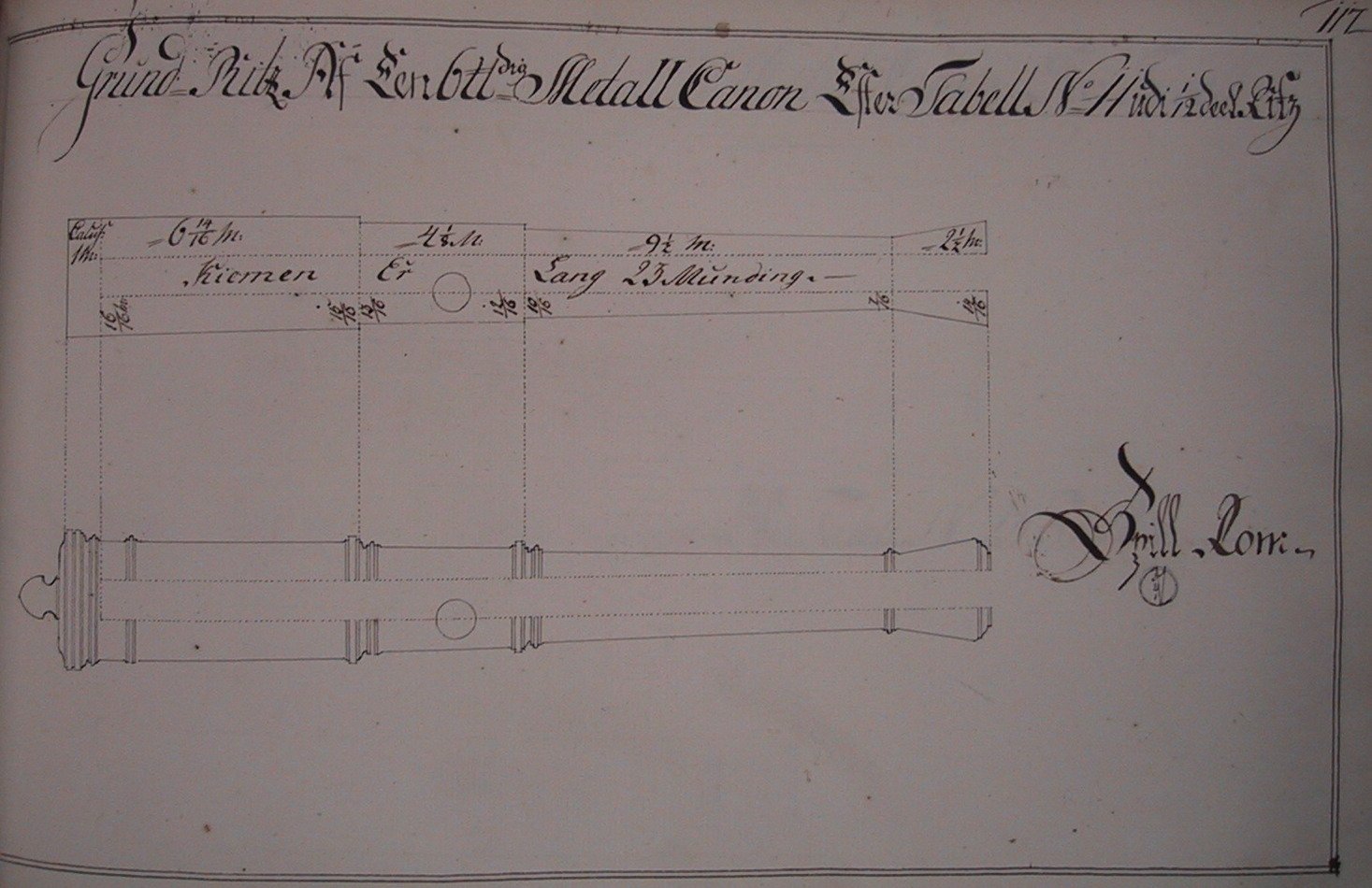
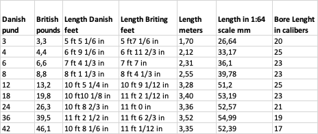
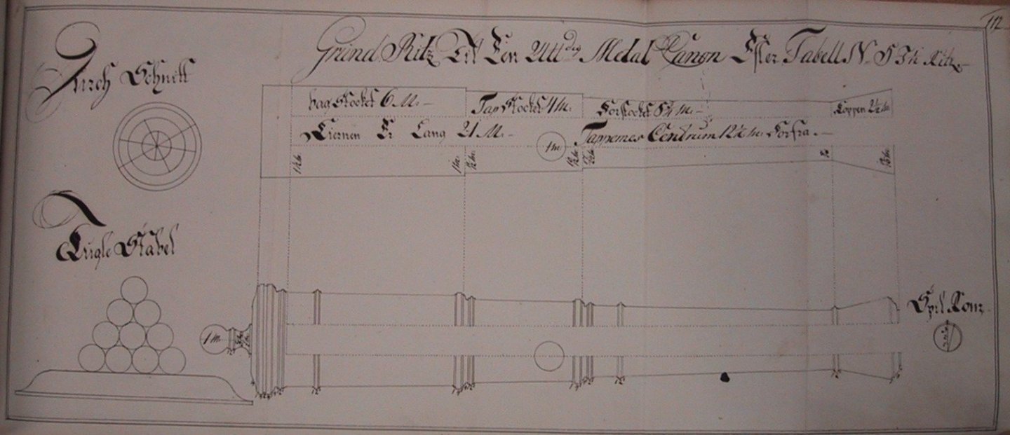
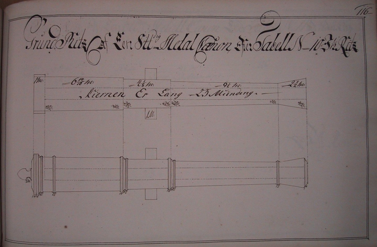
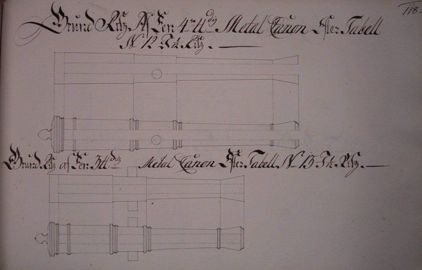
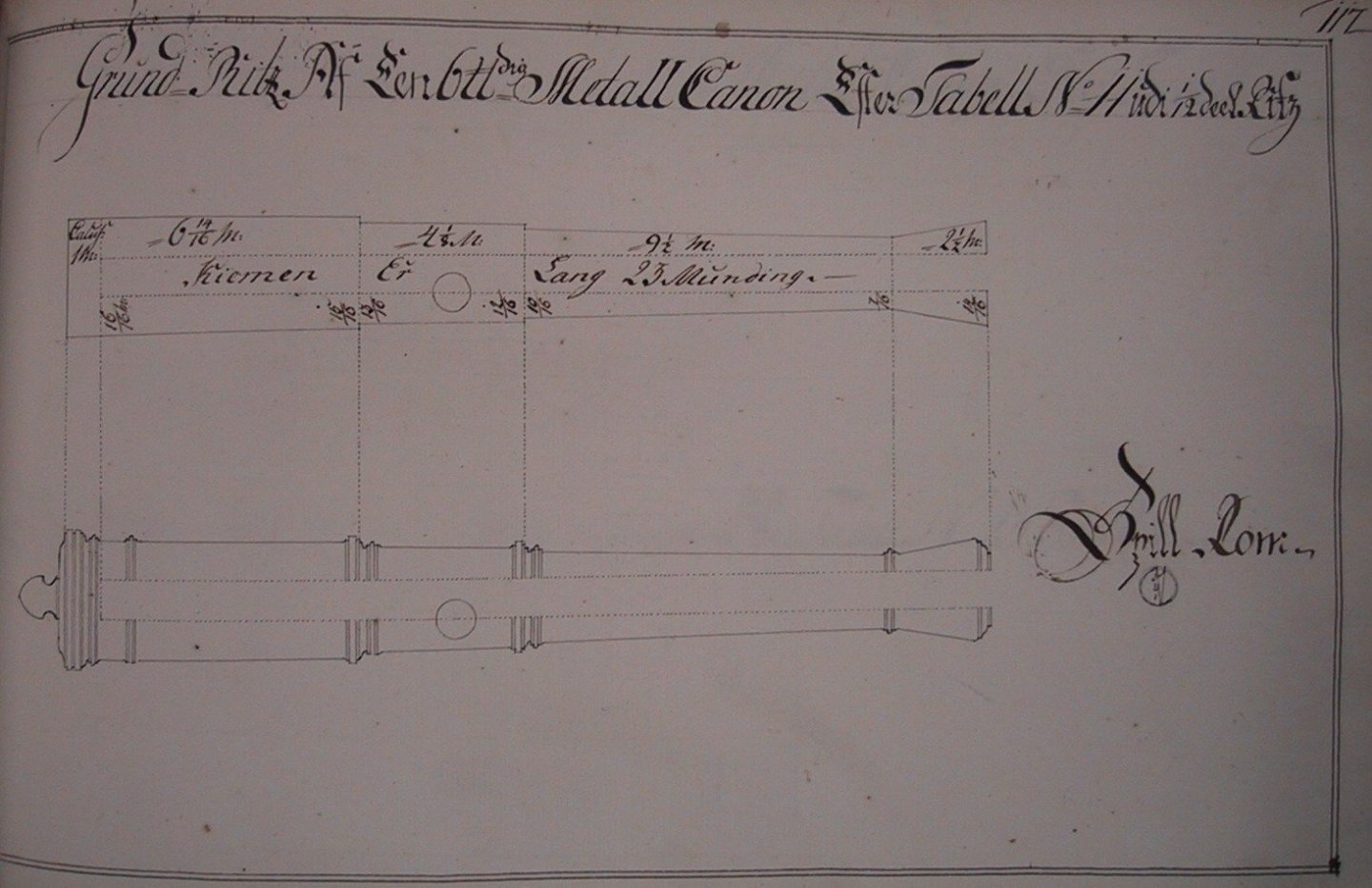
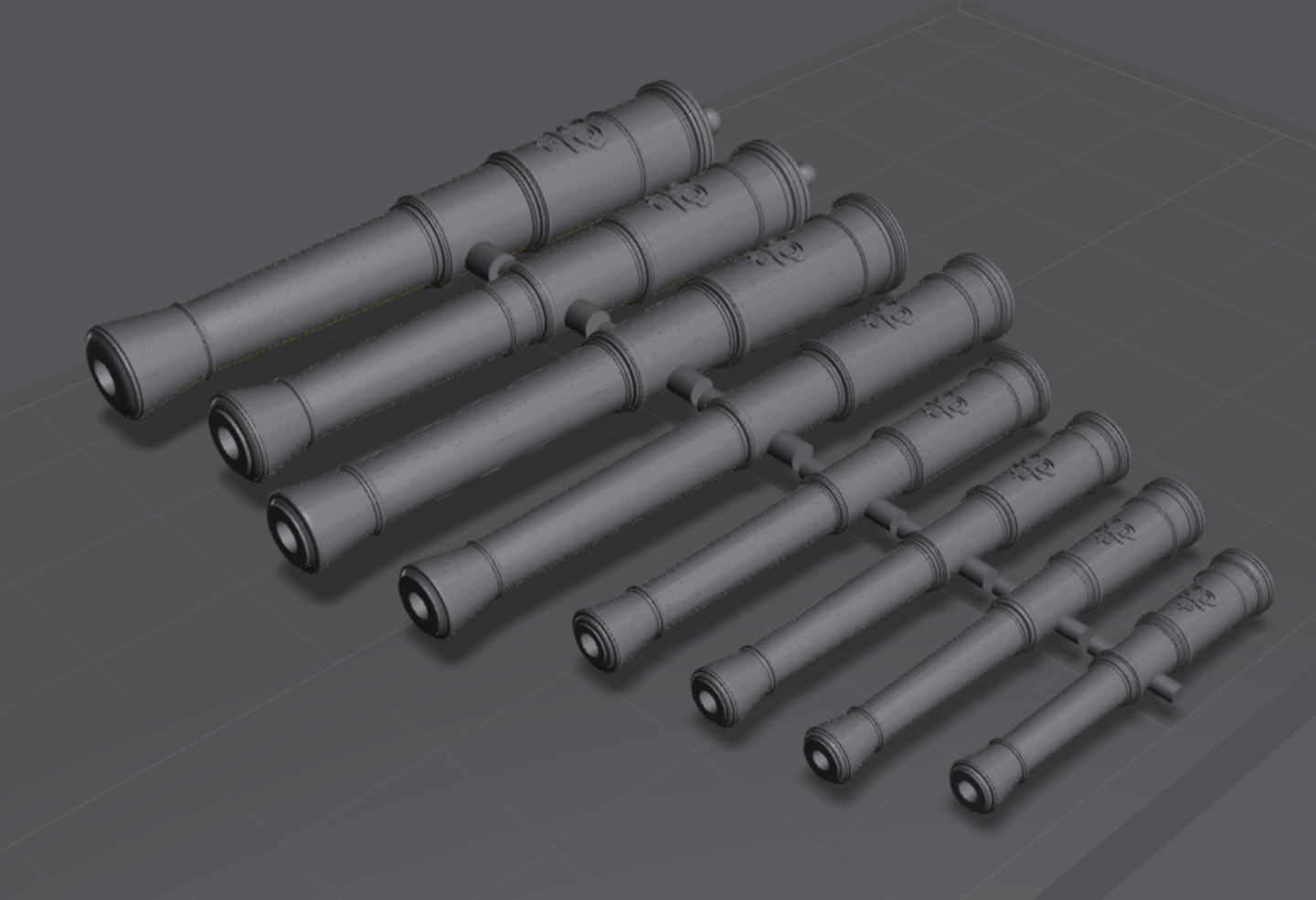
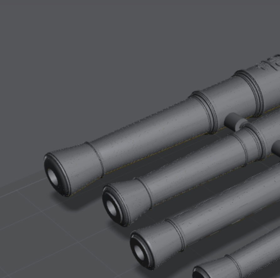
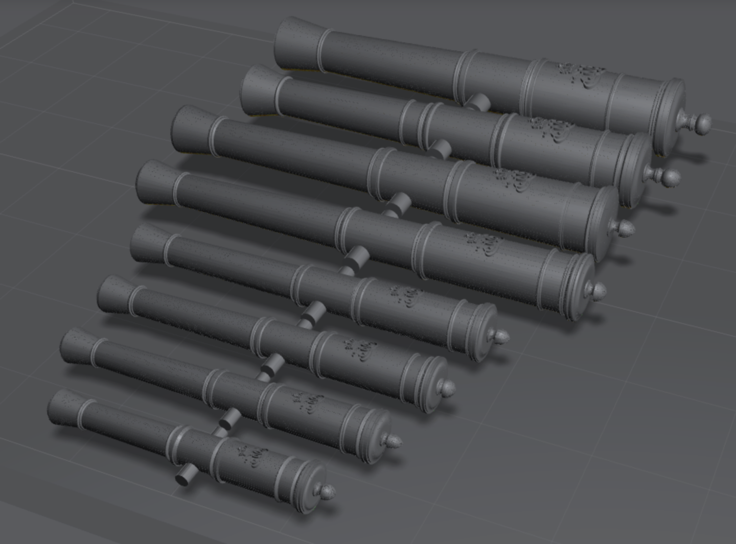
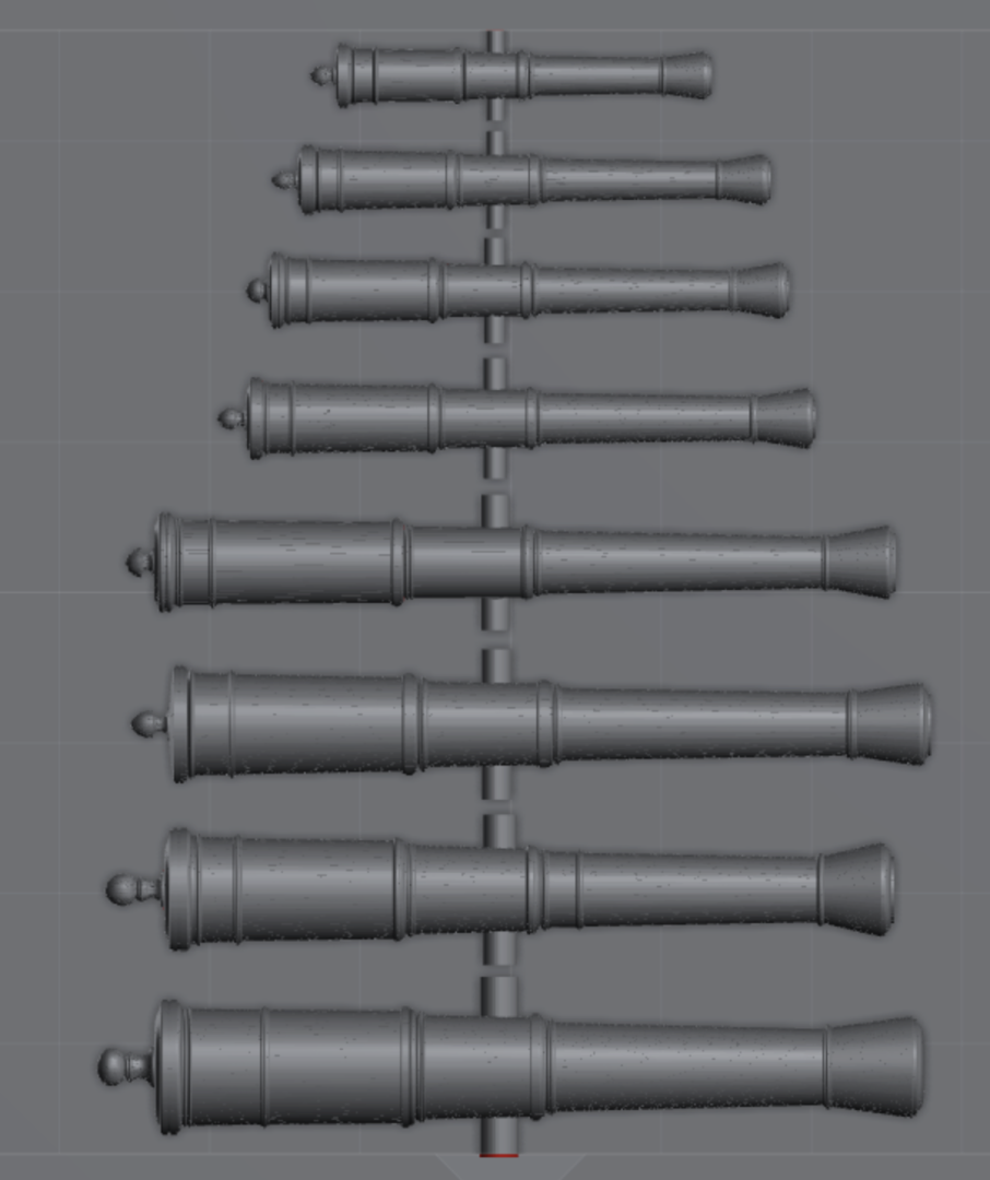
Hi All, Greatly inspired by @thibaultron's efforts to design and share 3D printable STL files for various series and times, I thought I would do the same for the very niche area of Danish Cannons. I am researching this for my own projects, and thought I would share with everyone. I will make occasional updates when I have new designs to share. For this first post, I have found a series of cannons from the period 1720-1750. They are from a Kaddet book and the scans cam be found here: https://www.arkeliet.no/sources/kadett_fm_1700/kadettbok1700t.htm The series is one of the most complete onse I have found and includes: 3 pdr, 4 pdr, 6 pdr, 8 pdr, 12 pdr, 18 pdr, 24 pdr, 36 pdr and 42 pdr cannon designs, sometimes severel versions/lenghts of each. I have started with just one lenght of each as can be seen in the table below. Here are the drawings used: Here you can see the files, except for the 42 pounder: And then I have versions with the monogram of King Christian VI, which should be appropriate for the period (though Frederik IV and Fredrik V could also be appropriate). You can see some of these (8, 18 and 36 pounders) printed in 1/32 scale in @Beckmann's build log for Tre Kroner. The STL files are in 1:64 scale, but are of course easily re-sizable to any other scale. I will attach the STLs in the next few posts BR TJM
-
@Arthur Goulart, as the drawings of artillery in the Danish Archive are rarely dated or directly connected to specific ships, there is unfortunately no nice way to find anything specific. So I do what you do and plow through the drawings. Have a look at F278-F360, there are quite a few artillery drawings in that range. A Norwegian site has scans of a Kadet book on Danish artillery. It was likely compiled in the 1720's-1750's: https://www.arkeliet.no/sources/kadett_fm_1700/kadettbok1700t.htm These are 'metal' canons, meaning bronze, as opposed to iron. BR TJM
-
Impeccable work Matthias! It's really coming together and showing the full shape snd design intricacies now. All those individual, subtly different balustrade columns are so well done!
-
I believe the wiki page just echoes the museum, but it will be very interesting to see if you have the display case text! Lex also calls it Christiania, referencing Orlogsbasen, Rigsarkivet: https://trap.lex.dk/Christiania_(1774) You may well be right here, and I agree that the drawing and the model are a match, but it is strange that current sources reference it as Christiania then! BR TJM
- 148 replies
-
- 1
-
-
- Christiania
- Vanguard Models
- (and 1 more)
-
This is the section in 'Danske Orlogsskibe 1690-1860. It agrees with your description, however, like I mentioned, I wonder why it is then labelled as Christianias figurehead at the museum!? And whether some new information has appeared since the 70's that changed the identification of the model?
- 148 replies
-
- 2
-
-
- Christiania
- Vanguard Models
- (and 1 more)
-
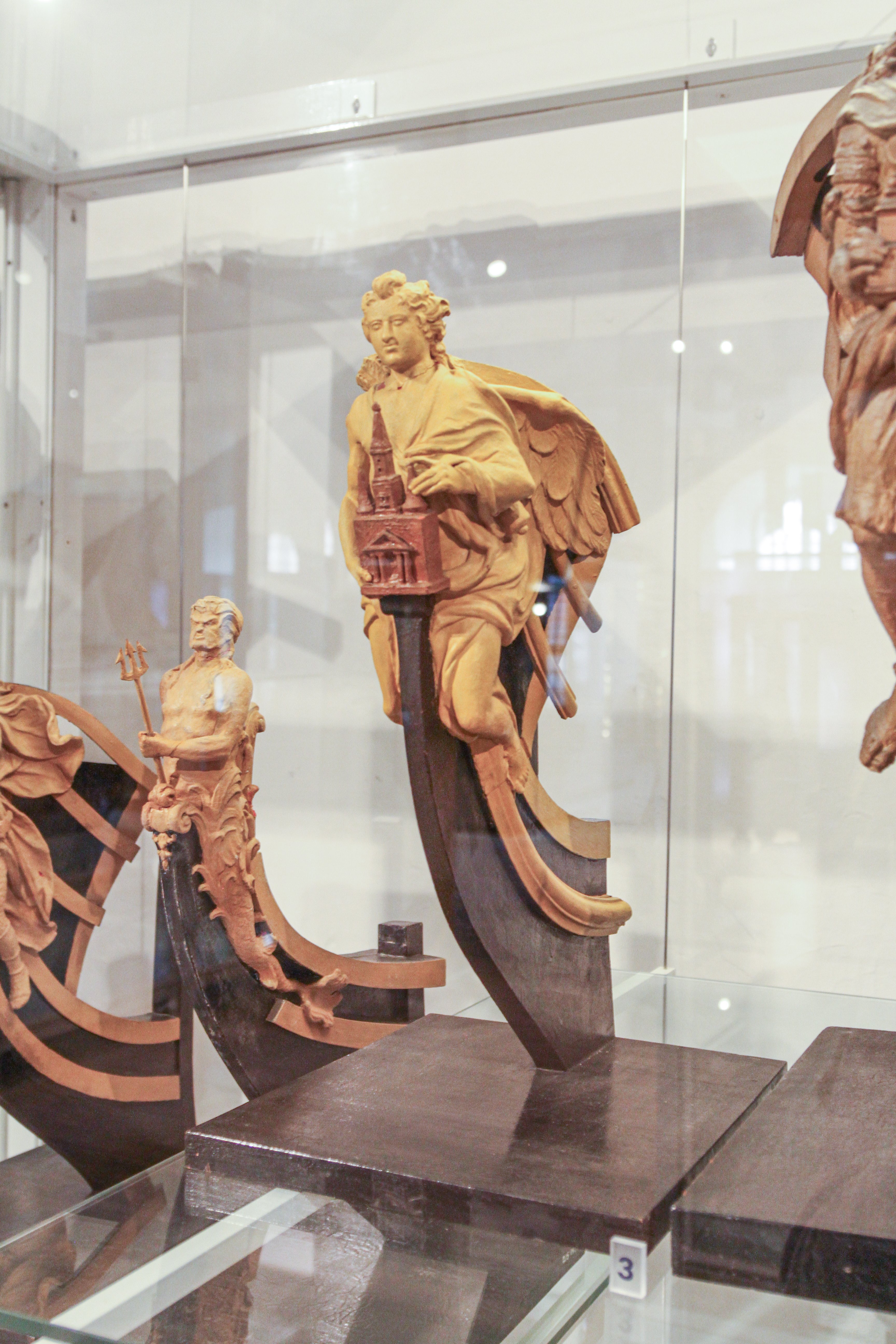
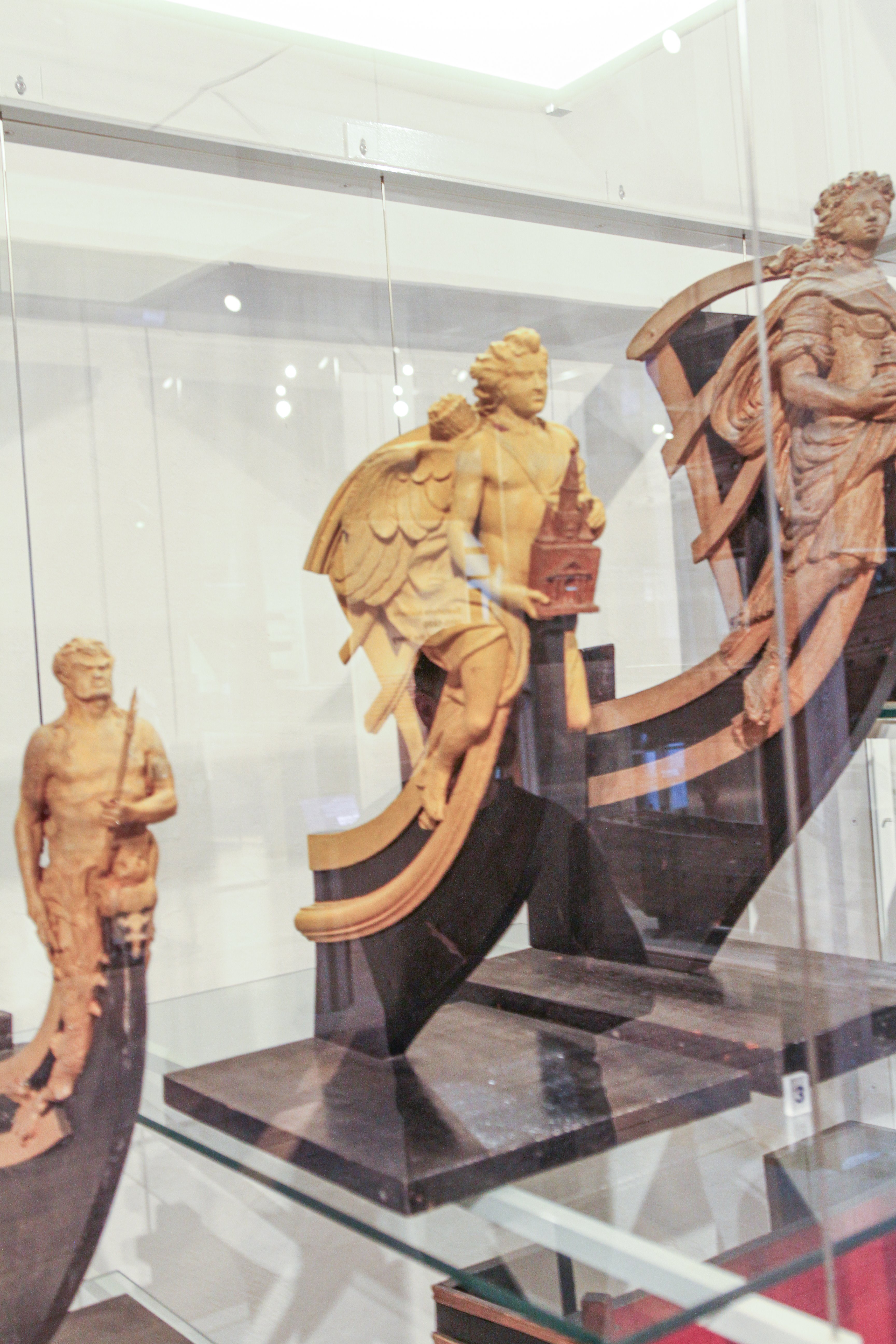
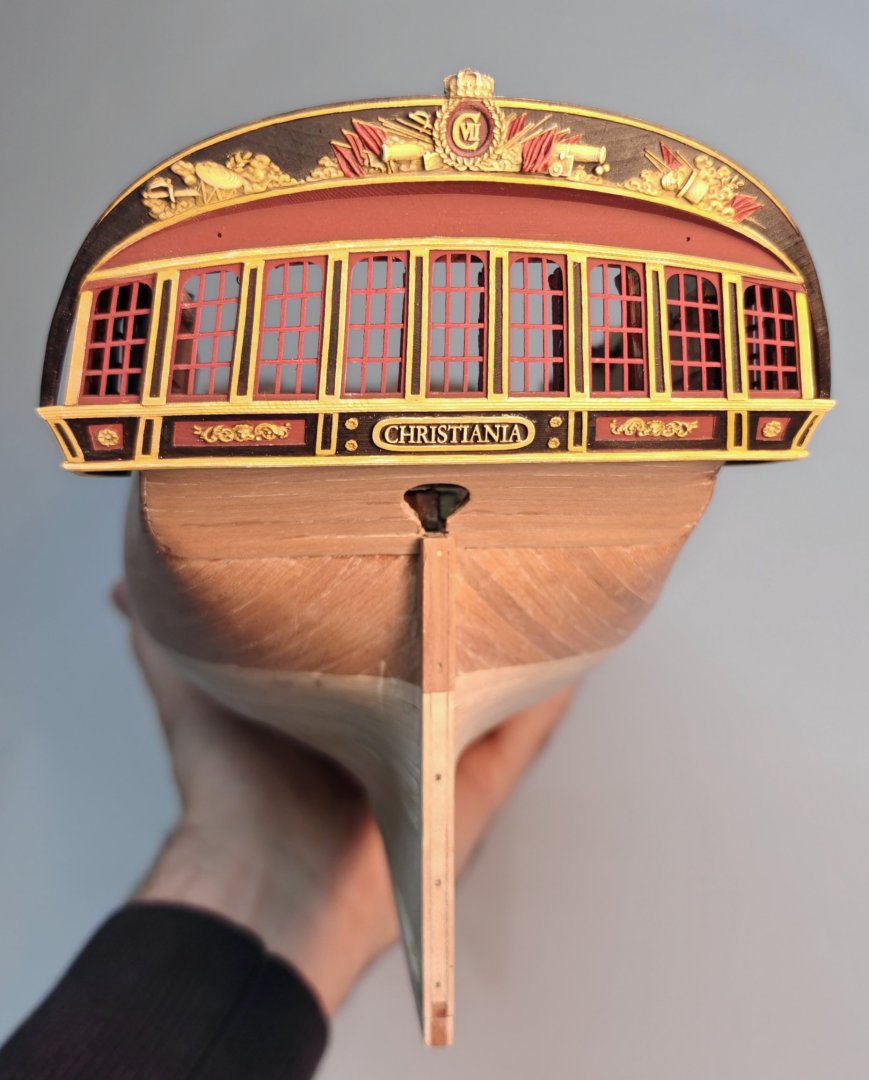
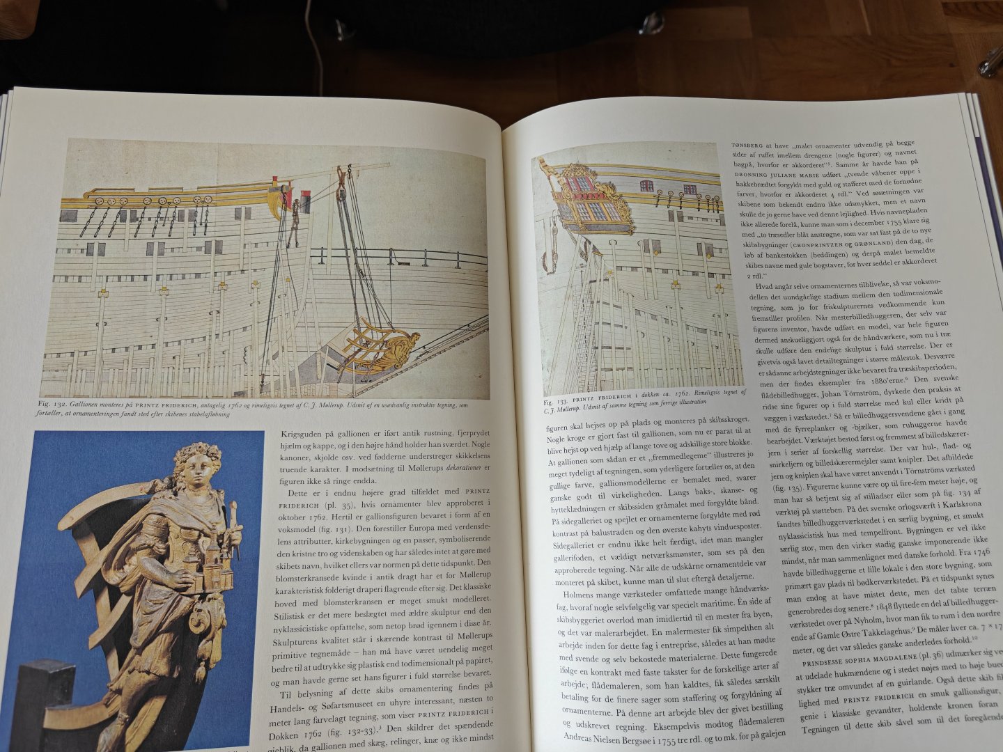
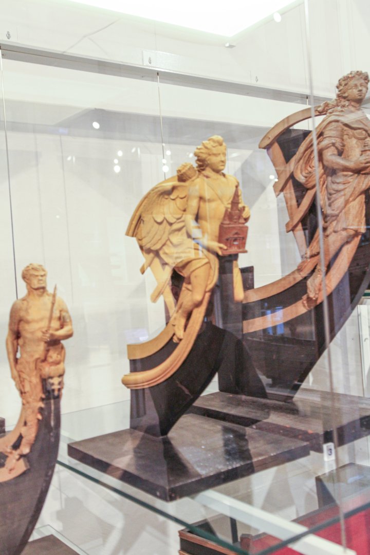
Hi Matthias, Thank you so much for your kind words and the very interesting comment! The figurehead is supposed to be that of Christiania, not the Printz Friderich and the model is identified as such in the museum. You will also find this on Wikipedia: https://commons.wikimedia.org/wiki/File:Galionsfigur_til_fregatten_Christiania_(model).JPG But I agree that it does look much like the coloured drawing of the mounting of the figurehead - I wonder if the same motif was re-used? It is a bit of a conundrum as the original plans does not show this exact motif, but rather a lion or another lady figure not holding a building. It does however seem like this figurehead model was previously identified as the one for Printz Friderich - it is mentioned as such in the 1979 book Danske Orlogsskibe 1690-1860. Perhaps it has later been re-identified as Christianias figurehead? Or perhaps the museum has it wrong! Unfortunately, my own photographs does not contain the annotation on the display case. There is another very similar figure just beside this one, could that be the Printz Friderich figurehead? What do you think? BR TJM

- 148 replies
-
- 2
-
-
- Christiania
- Vanguard Models
- (and 1 more)
-
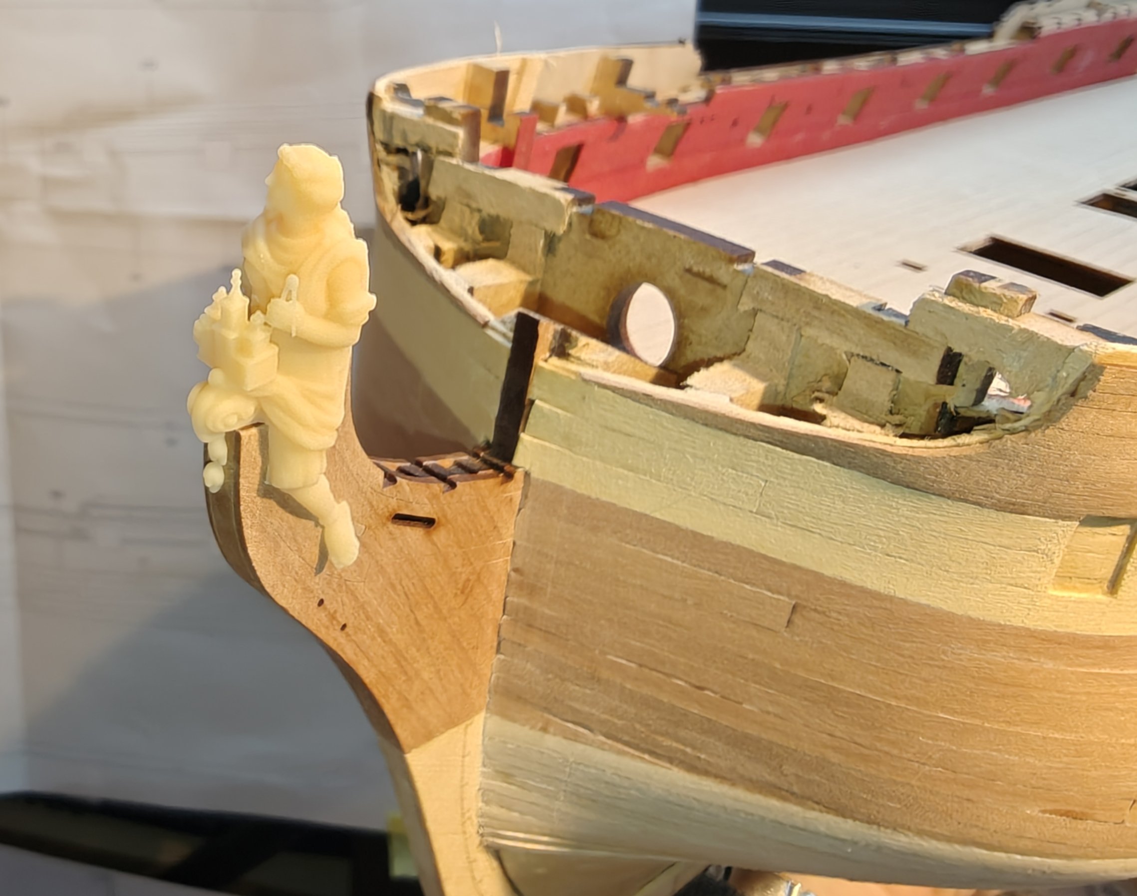
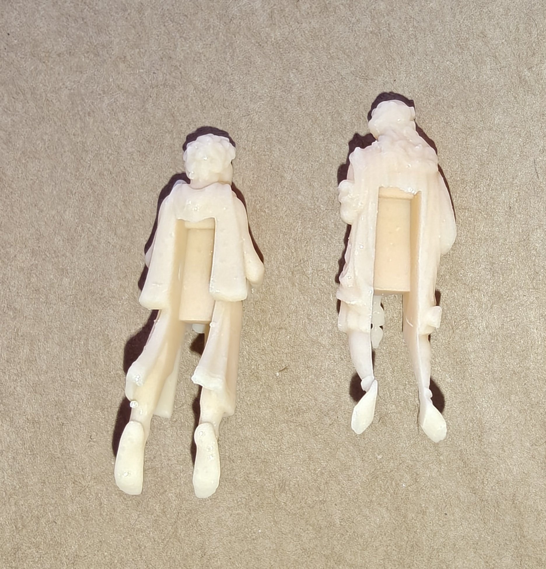
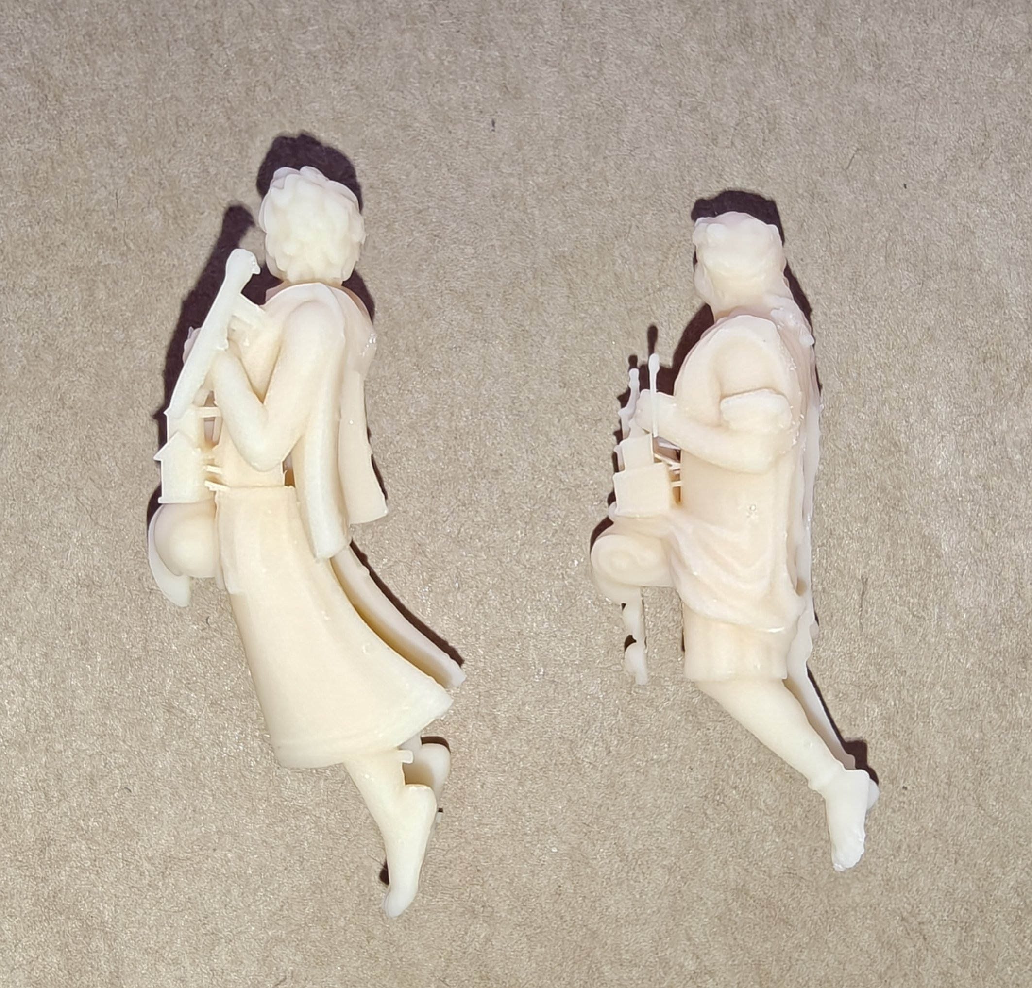
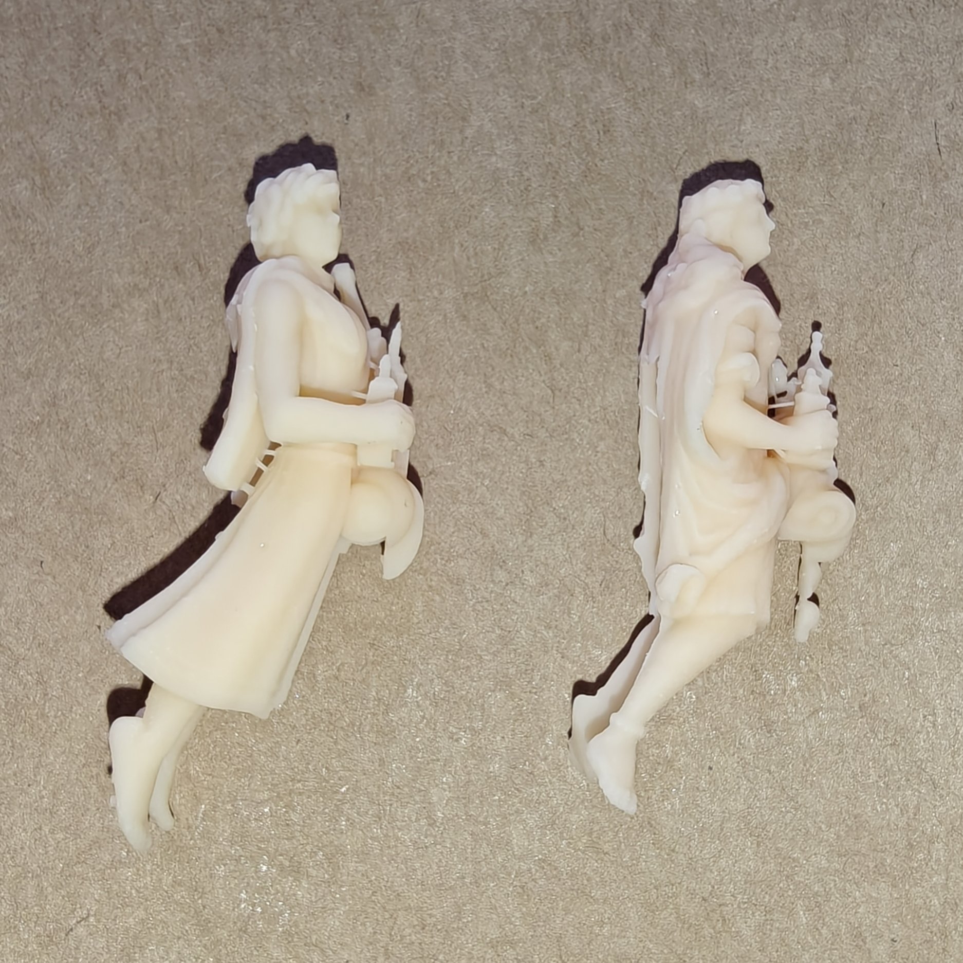
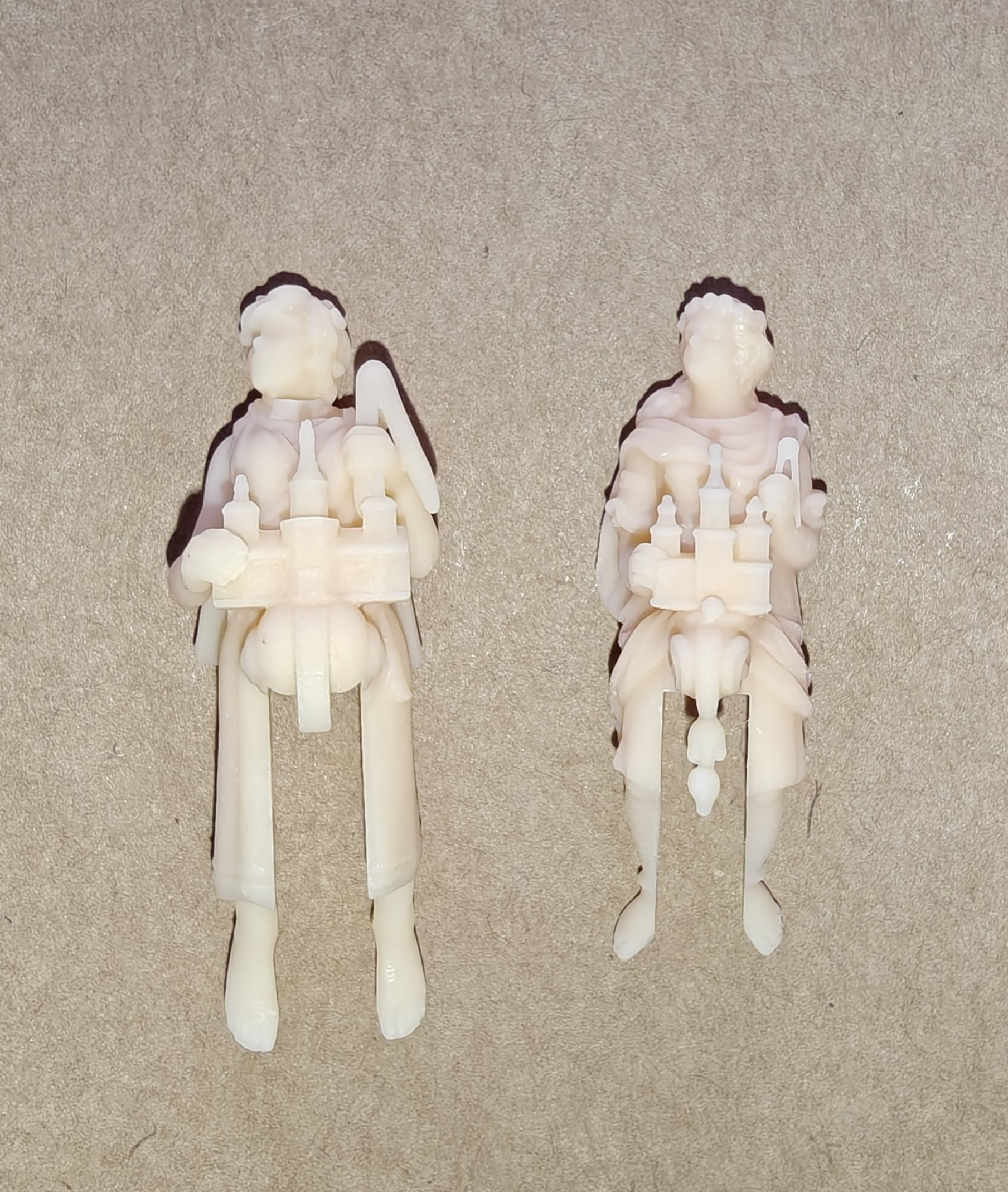
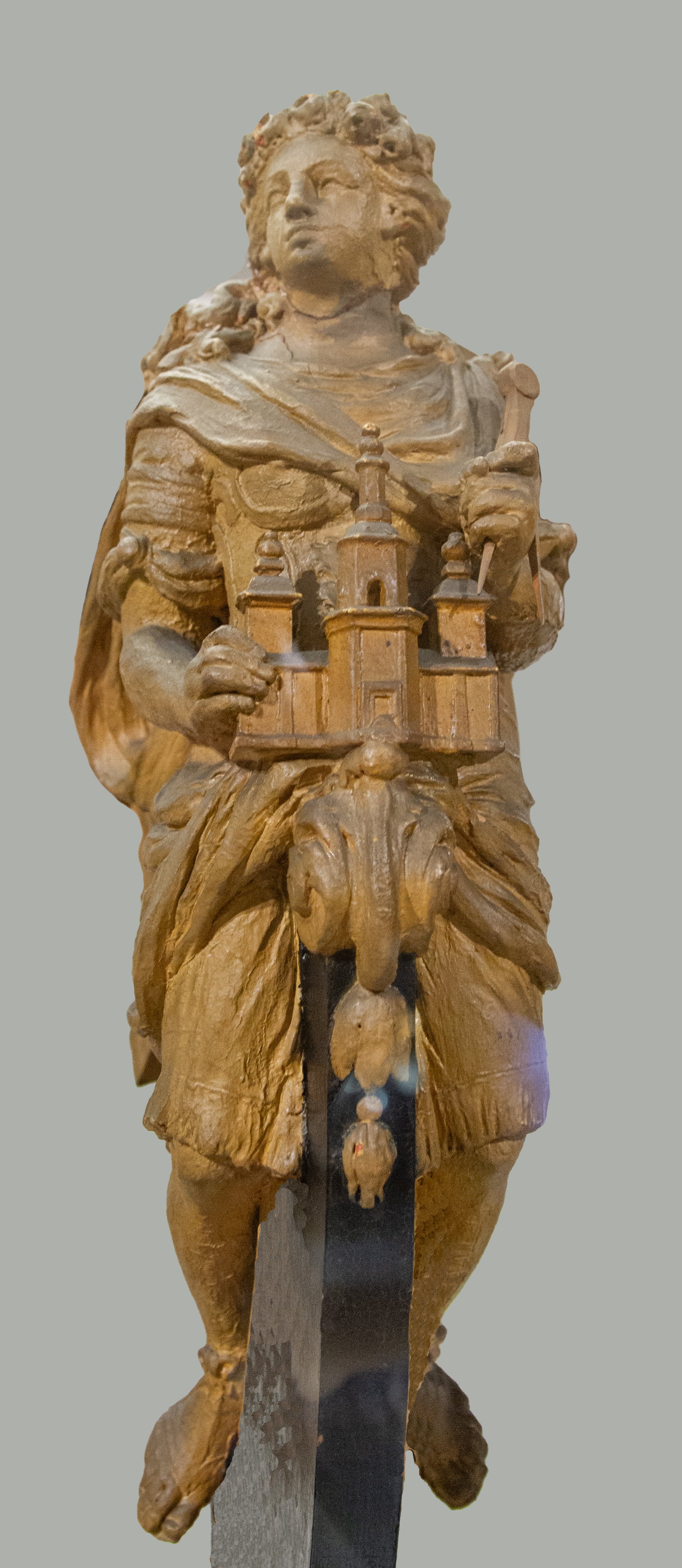
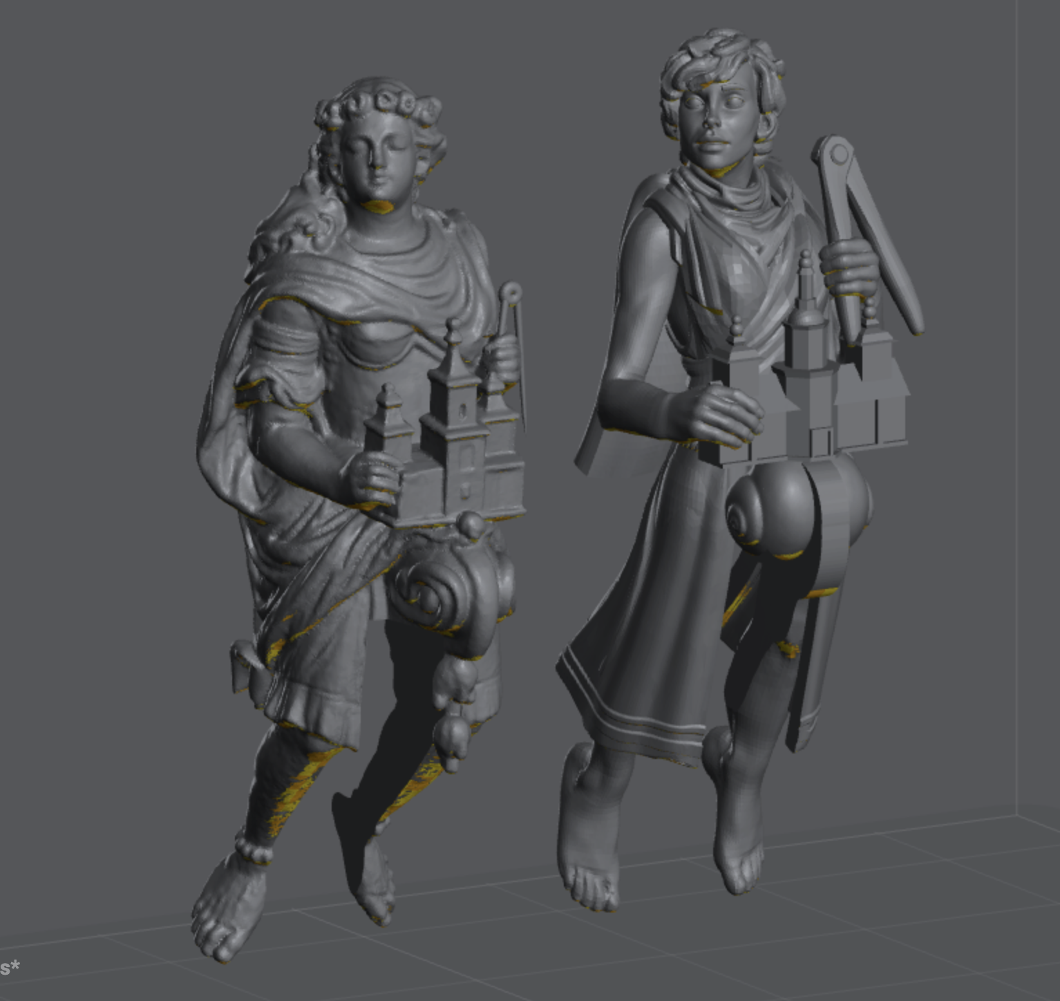
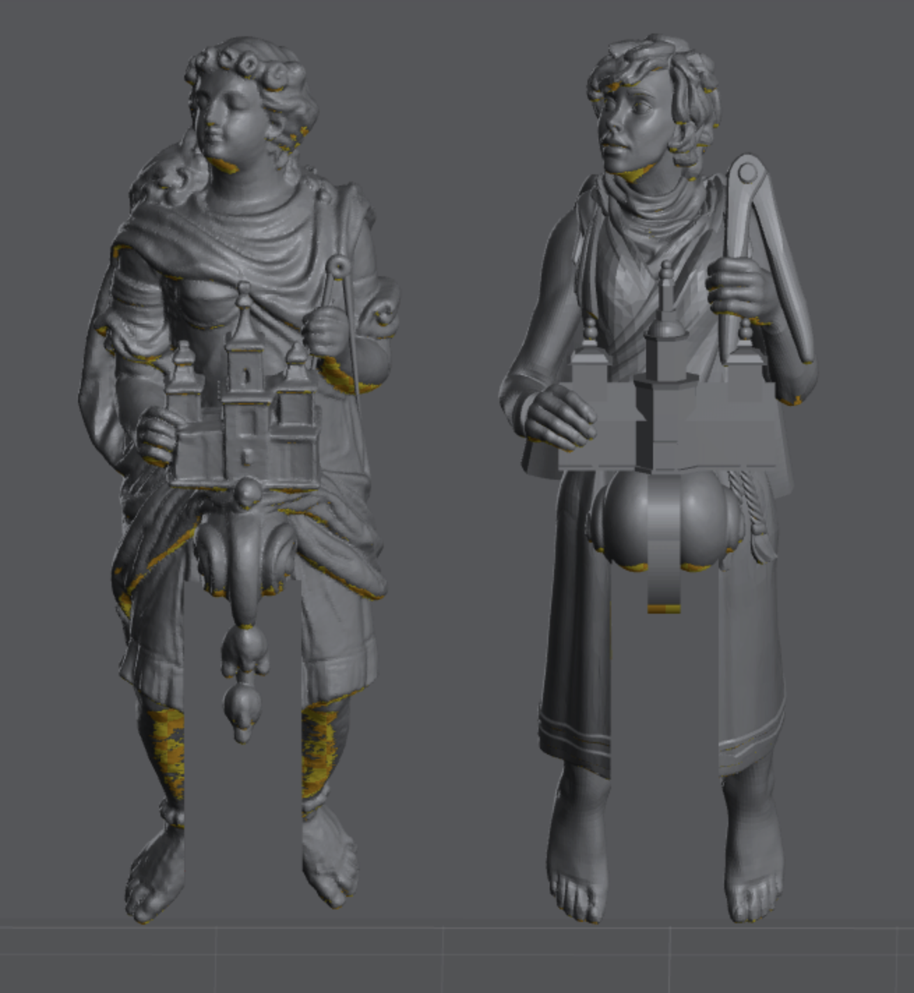
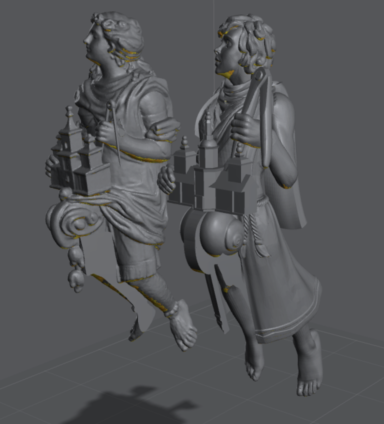
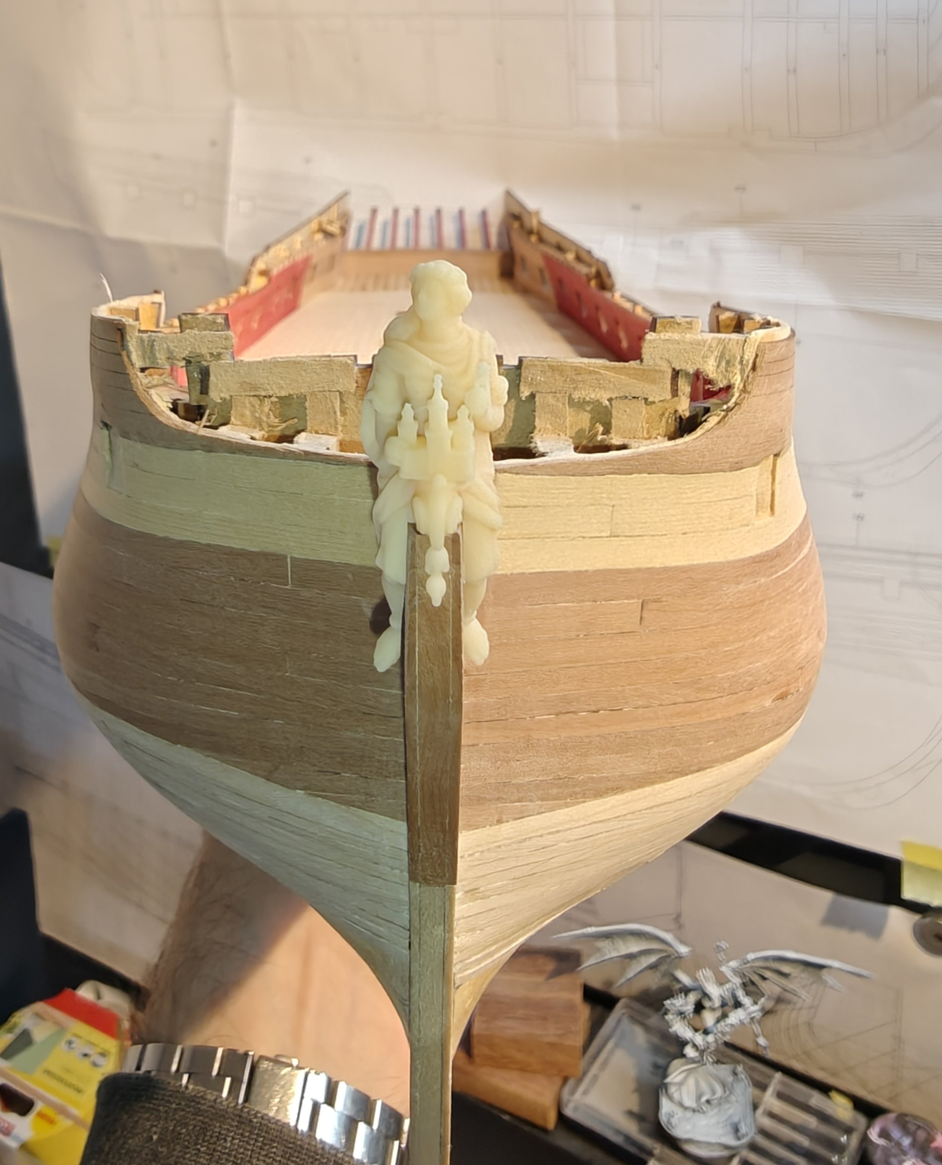
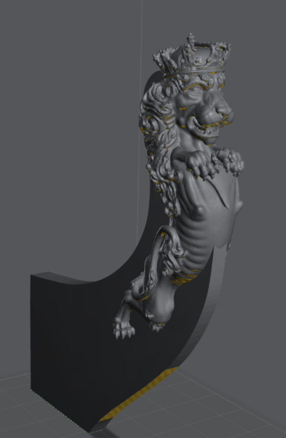
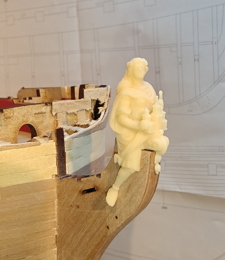
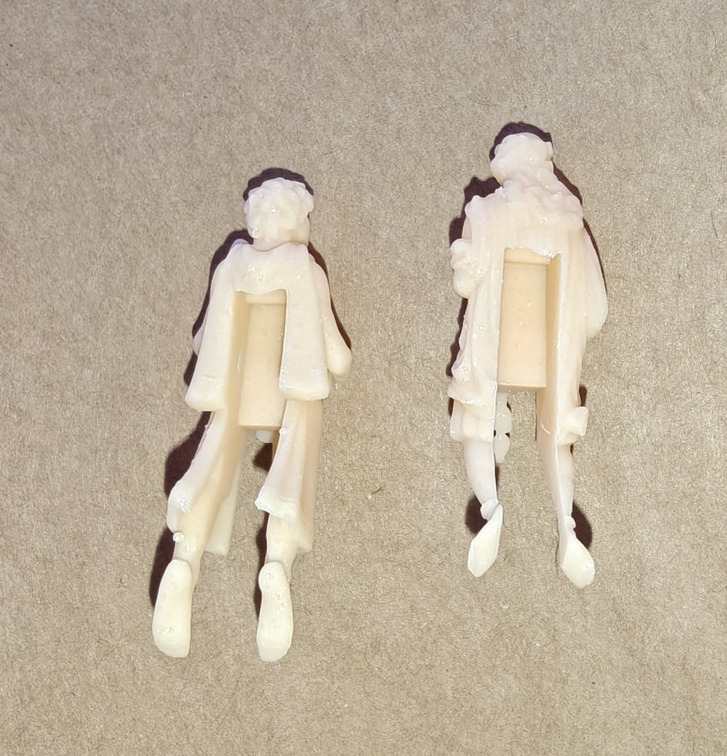
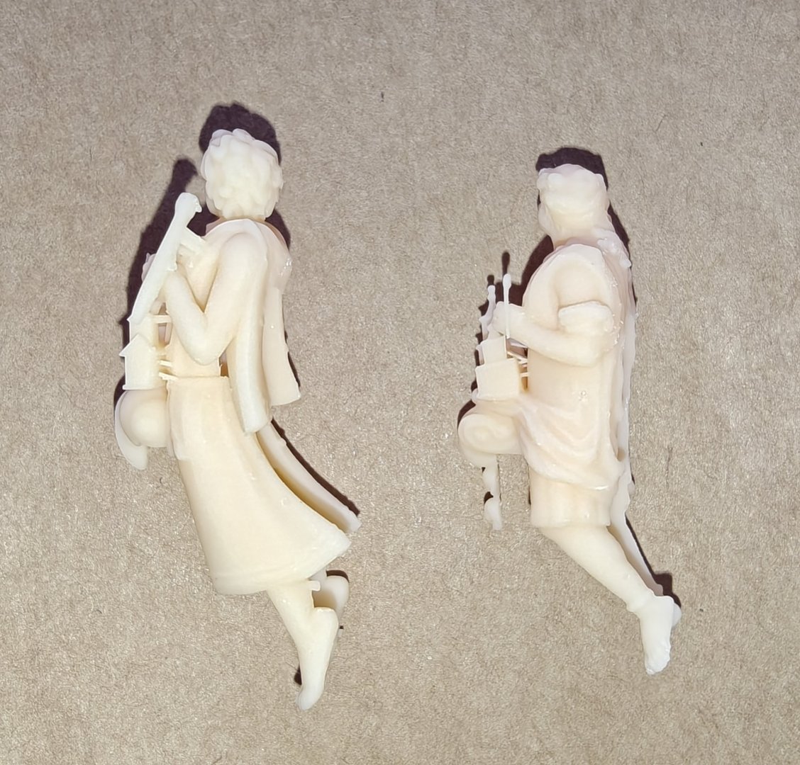
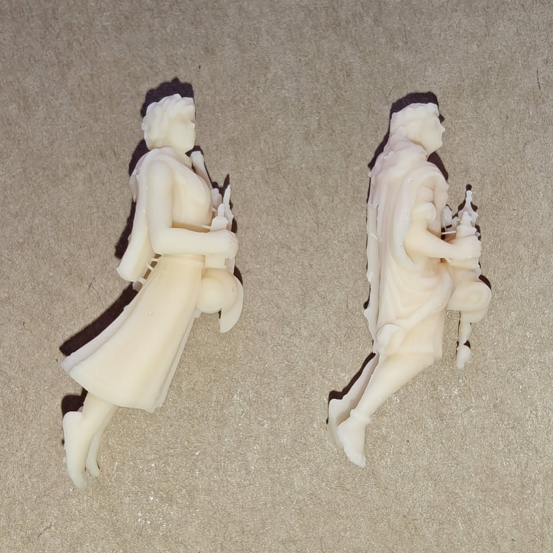
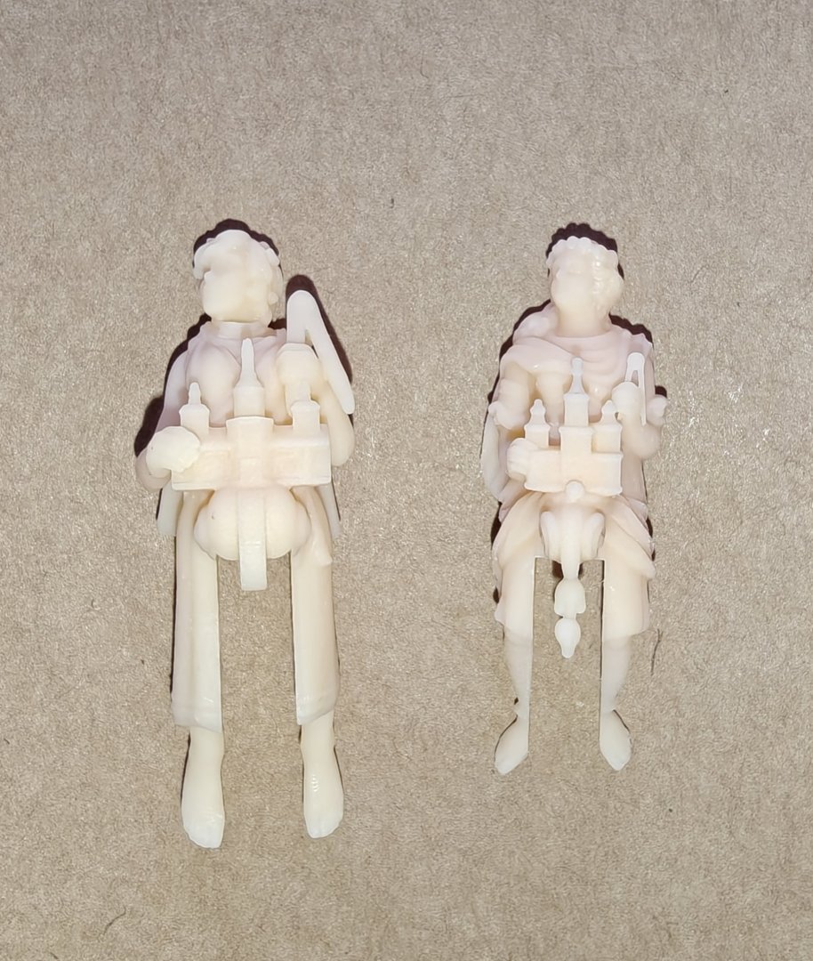
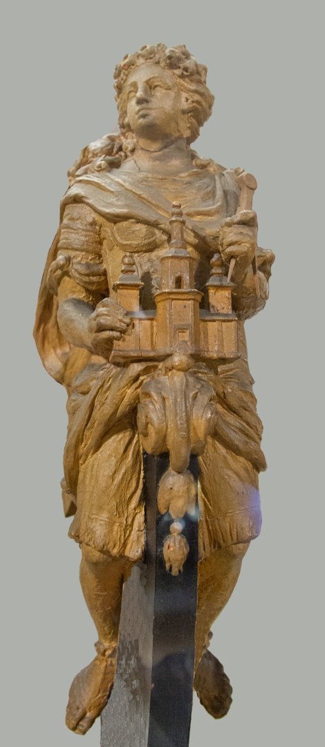
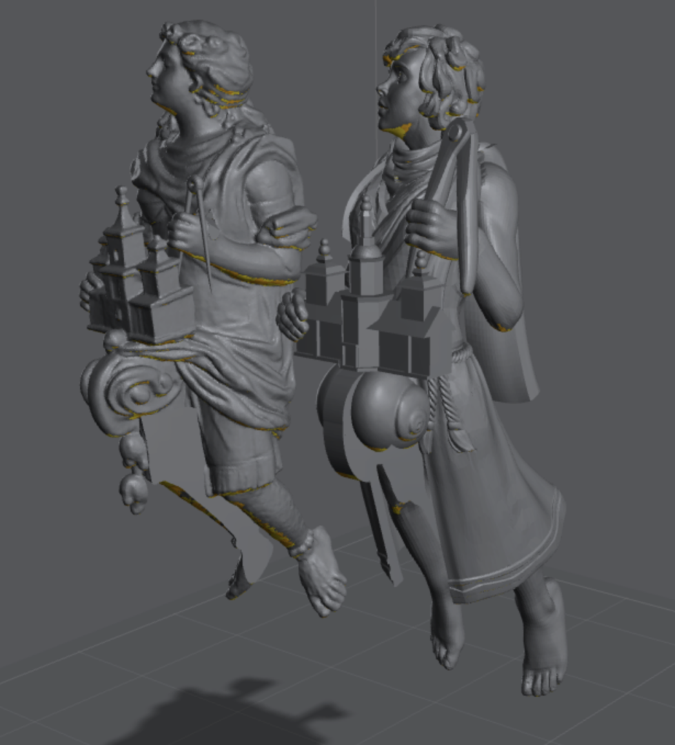
Log entry 31 - a new figurehead A while back, I made a figurehead for Christiania using Hero Forge. I was quite happy with it, as the pose and motif was faithful, though the details were somewhat different to the original. But now, as can be seen in Chucks recent post in the 3D modelling sub-forum, Meshy AI has become really good at making a 3D model from just one image. So I had to try to re-do the figurehead with this new tool. Here's the cleaned up image I fed to Meshy: Here i have removed headworks and the other details on the keel. I have taken this photo myself at Krigsmuseet in Copenhagen where the model of the figurehead is displayed. Meshy gives you 5 runs/tries when you submit a task. I submitted twice, and used 7-8 runs to get the version I went with. They were all very good, but I needed a version with space for the keel between the legs and with no weird stuff in the left hand. The Meshy models look great and can be printed as is, however I need a slot for the prow and it is really a pain to get a single solid with no topological issues. but after a few hours of trial and error, I managed. Here's a comparison of my Hero Forge figurehead and the new Meshy one: Honestly, the Meshy one is much better, as the style is correct. It is very close to the original model at the museum. Btw, I did the callipers myself, the AI could not get that right from that angle. Here's printed comparisons: I know there is a bit of a size difference here as well, but you can clearly see that the pose is also much better and more natural in the Meshy version. Finally here's some shots of the figurehead on the model - the fit is great and I have just 0.5 mm of filing on the prow to make it perfect. I am super happy about this upgrade to the figurehead! BR TJM


- 148 replies
-
- 8
-
-
-
- Christiania
- Vanguard Models
- (and 1 more)
-
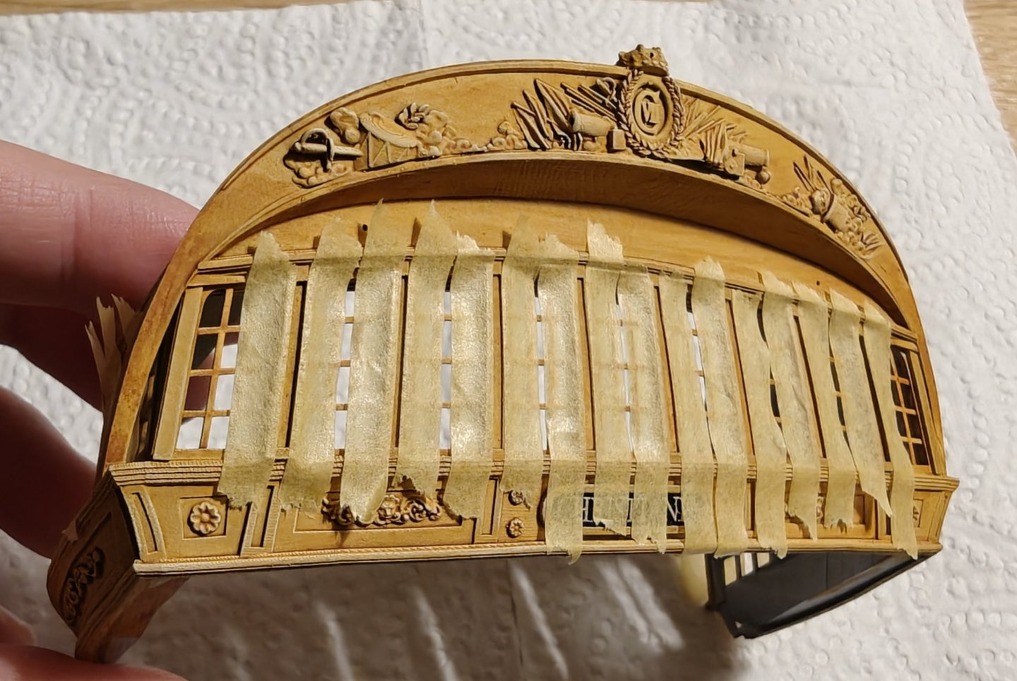
Ok, so I tried the reverse strategy for the painting. It may seem a bit foolish but there was a reason to try this, that I will get to. Here's how it went: The part was base coated, first with black, then with white. I use an airbrush for this. Then I used an Army Painter brown Speedpaint to get a dark yellow base. Speedpaints (like Citadel Contrast paints) are basically heavy pigment acrylic inks that will run into the recesses, but also leave a nice base colour on the raised parts. It is meant to be one coat and done. It looks super blotchy, as it is not so well suited for flat surfaces, but that is ok, it works where the yellow will be, particularly the friese. Next, I went owe the yellow with the ochre, mostly drybrushing: And then topped it off with a drybrush of beige for the highlights: After this I sealed it with an acrylic varnish and let it dry completely (a full day). So far, so good. Now comes the tricky part: tye recessed black parts. I did my best to mask off the yellow: But even then, the black seeped onto the yellow 😭. This was not really unexpected, but I had hoped masking it off would work better. I stopped here, as even if I could go over and clean up the yellow, the black edges are not straight enough and the point of doing it this way disappears if I have to re-do the yellow. So, the reason for trying this way is that drybrushing is very messy, especially when you have large, flat areas of a very different colour around the areas being drybrushed - as I do. Drybrushing the yellow gave a really nice result, the best I have achieved so far, but I can't get the black good enough. It is almost impossible to paint recesses without messing up the higher parts. Oh well. I will go back and do it the traditional way, building up the colours from lowest to highest. That just means I have to extremely precisely paint the yellow parts (of which there are many!) several times as I built up the colours... 😅. After white, yellow is the most difficult colour to get a good finish on. Anyways, back to painting the second version.... BR TJM


- 148 replies
-
- 7
-
-
- Christiania
- Vanguard Models
- (and 1 more)
-
Thank you Matthias, that is very kind of you to say, but I think there are some improvements needed 😃. I have been painting Warhammer miniatures for a long time, but their 32 mm scale and fantasy/sci-fi style is much easier to paint compared to naturalistic 1:64 scale! 😅
- 148 replies
-
- 2
-
-
- Christiania
- Vanguard Models
- (and 1 more)
-
Thanks for all the likes! And thank you @Ronald-V and @brunnels for your kind and encouraging words! BR TJM
- 148 replies
-
- 1
-
-
- Christiania
- Vanguard Models
- (and 1 more)
-
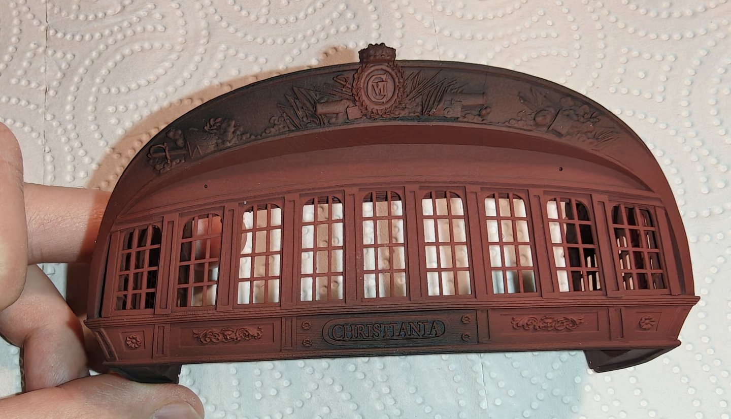
Log entry 30 - final(?) stern version and a colour test After a few quite some iterations, I now have a fit that I am happy with. And I like the design. With an additional plank added below the stern and the lower parts of the side galleries made from wood (that will be a small challenge as well), I think this will be good. I made a colour test from the last version (the one that didn't fit as well as this newest one), as the only things I am 100% settled on is that the windows will be red and the friese and ornaments will be yellow ochre. So I did not aim for a super neat paint job here and have used mostly flat colours with minimal shadows and highlights. This is just to evaluate the colour palette: I am resonably happy. Or, I should say, I like this colour scheme, but I am a bit apprehensive about the prospect of actually trying to make a super neat paint job. It is extremely difficult! And even though I am out of training, I have been doing miniature painting for over 25 years and this is really some of the most difficult I have tried. The print is so crisp and nice and I feel I butcher all that lovely detail with globs of paint! Organic shapes are much easier to paint than flat surfaces or straight lines! This test took me at least 4-5 hours to paint, and I will have to go much slower, with more, thinner layers for the final version. I am considering if I should try a contrast paint method, basically a wash method, to get the basics colours in and then do a single pass of main colour and highlights for the yellow. I could perhaps also mask off and airbrush the red in after the initial wash. Or I could airbrush it all yellow, mask off and do the red and then add the black after. Hmmm, I will think about this while I continue with the planking .... BR TJM


- 148 replies
-
- 15
-
-
-
- Christiania
- Vanguard Models
- (and 1 more)
-
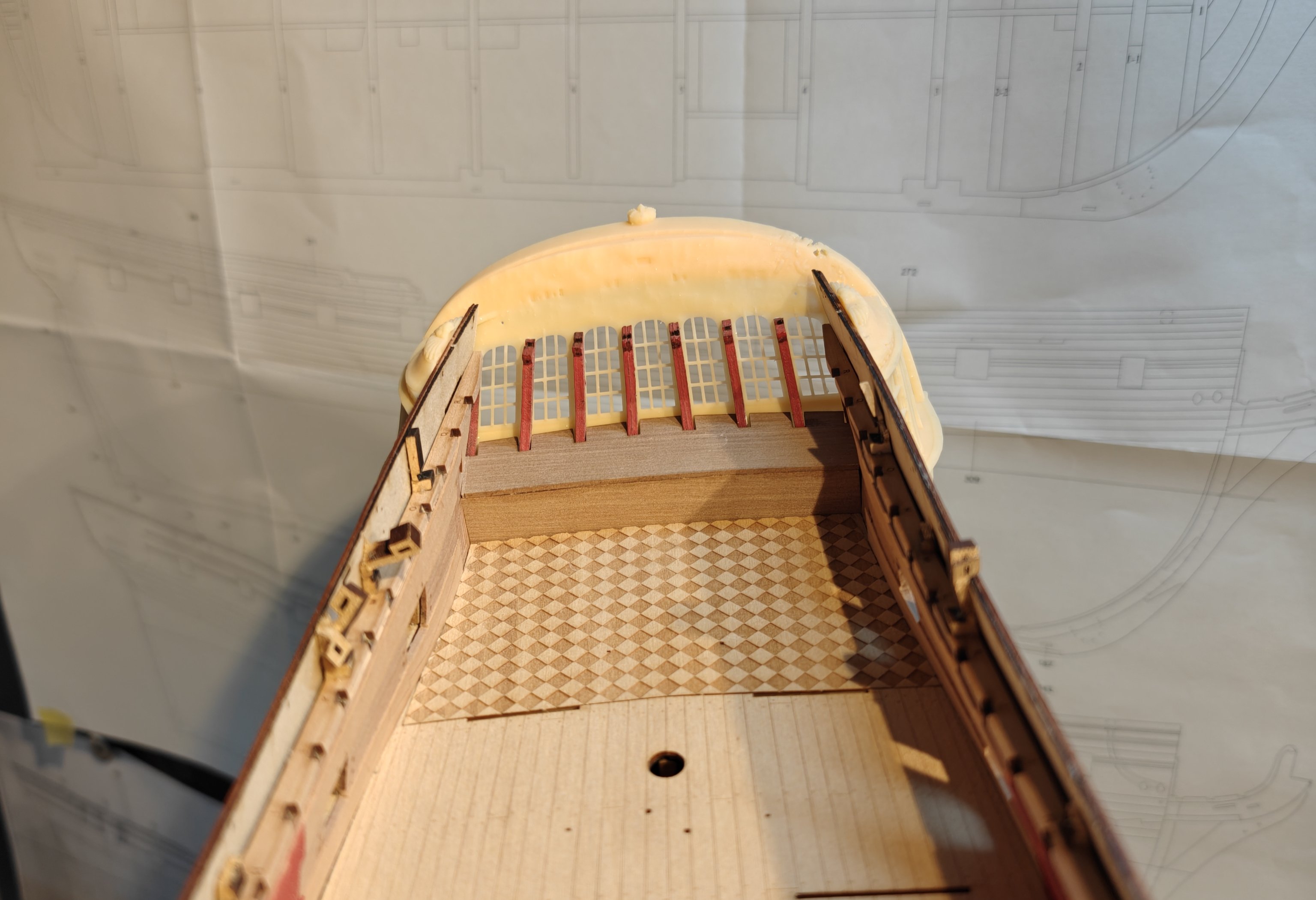
I made the adjustments but it is really hard to see on the photos. The whole window section is now curving and I took the opportunity to add lower stern decorations. These are made with Meshy.ai, see the recent discussion on the 3D modelling sub-forum, and will be the first aI generated elements I use. The fit is much better, but there are still room for improvement. I also have a weird bend at the top of the side galleries, symmetrical on both sides. This is a printing issue, but I am not sure what happened. Something shifted or there is a lack of supports that make the model sag or compress. I also have a lot of support residues on the side galleries, a result from trying to support the bars to prevent bending during printing. But i changed the release film on the resin vat and am getting crisp prints across the build plate again, so that is nice! I have to look into the printing technicalities and also make another small adjustment to the angle of the side galleries to improve the fit further. But it is getting closer 🙂.

- 148 replies
-
- 13
-
-
- Christiania
- Vanguard Models
- (and 1 more)
-
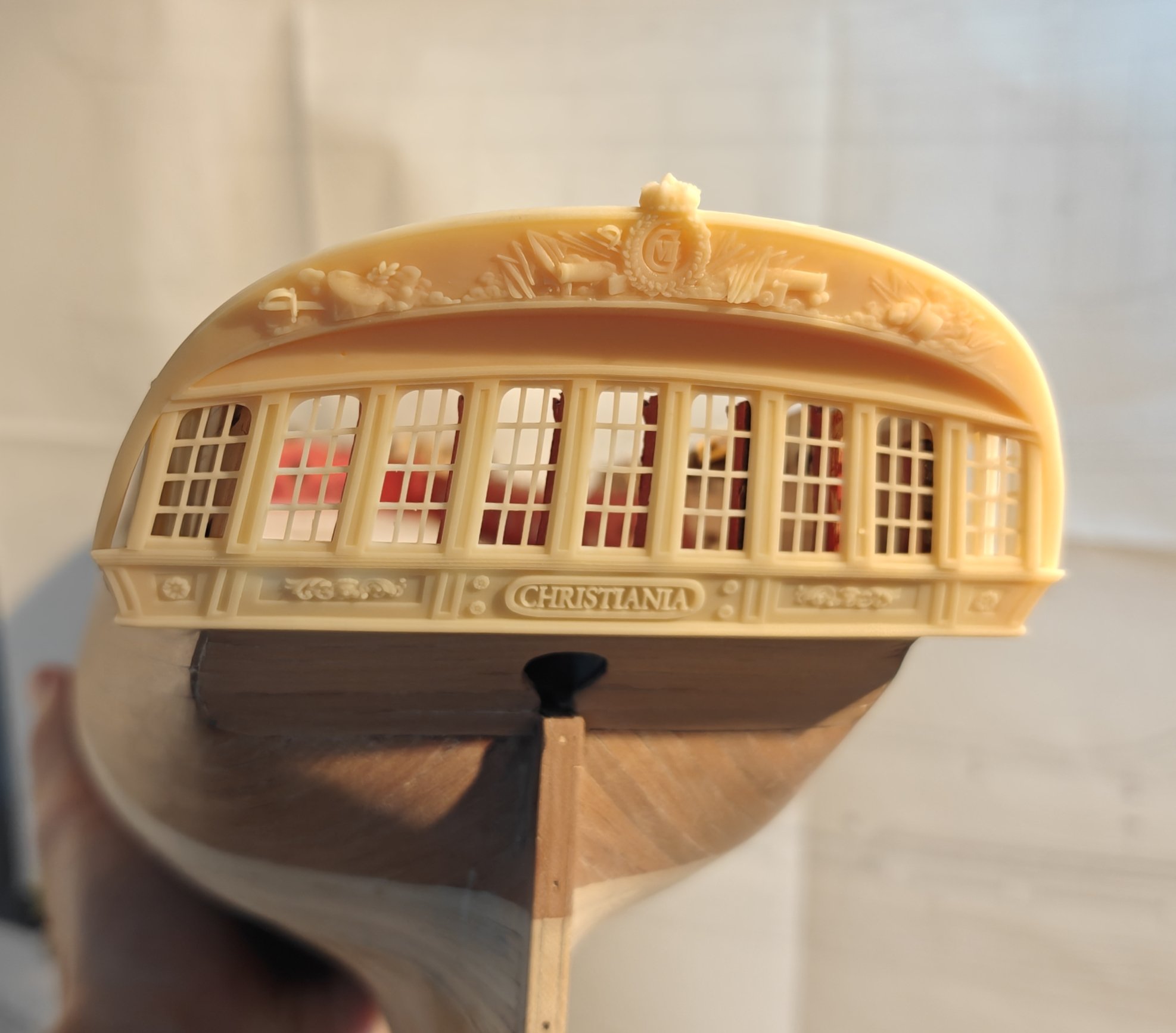
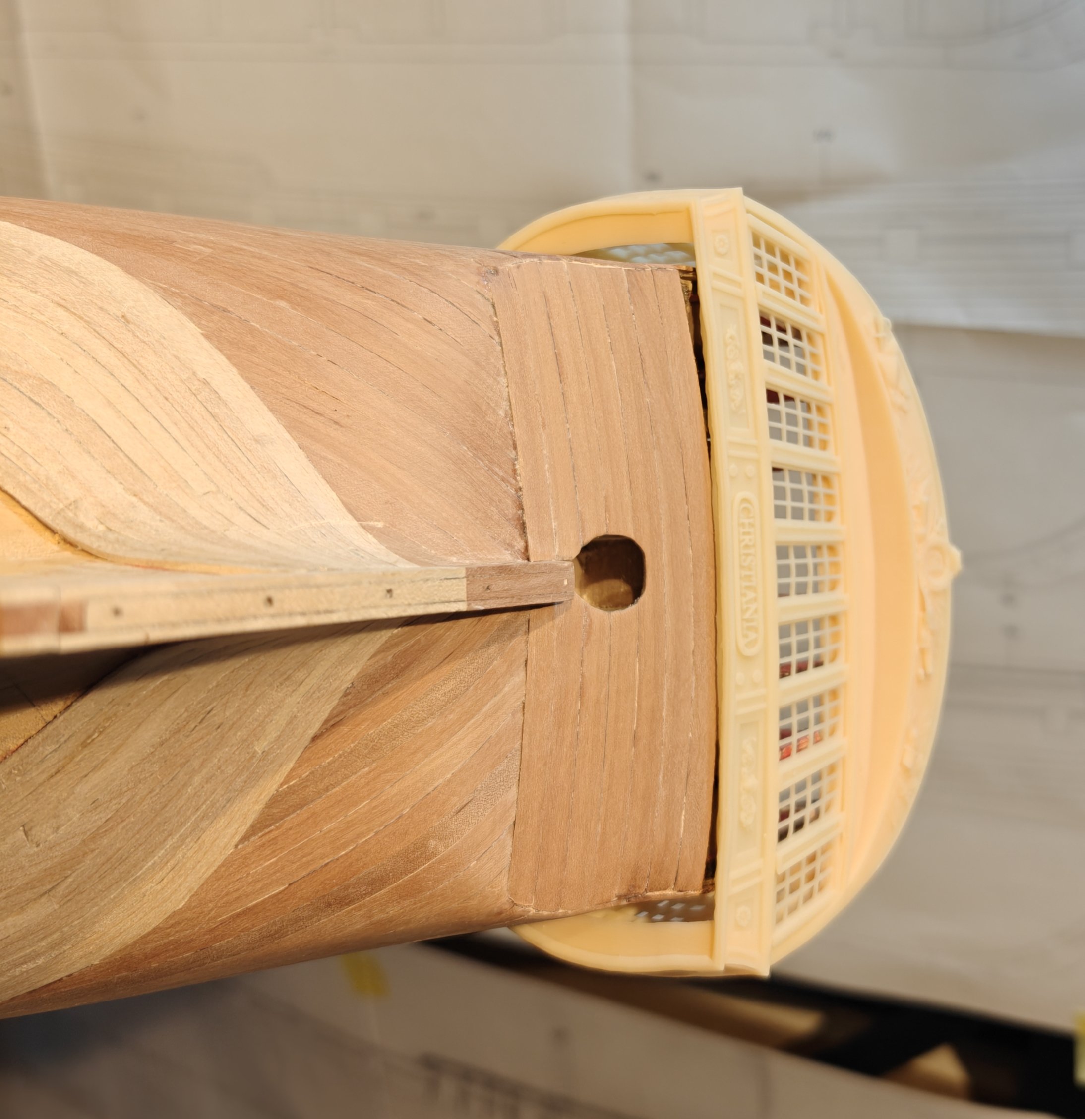
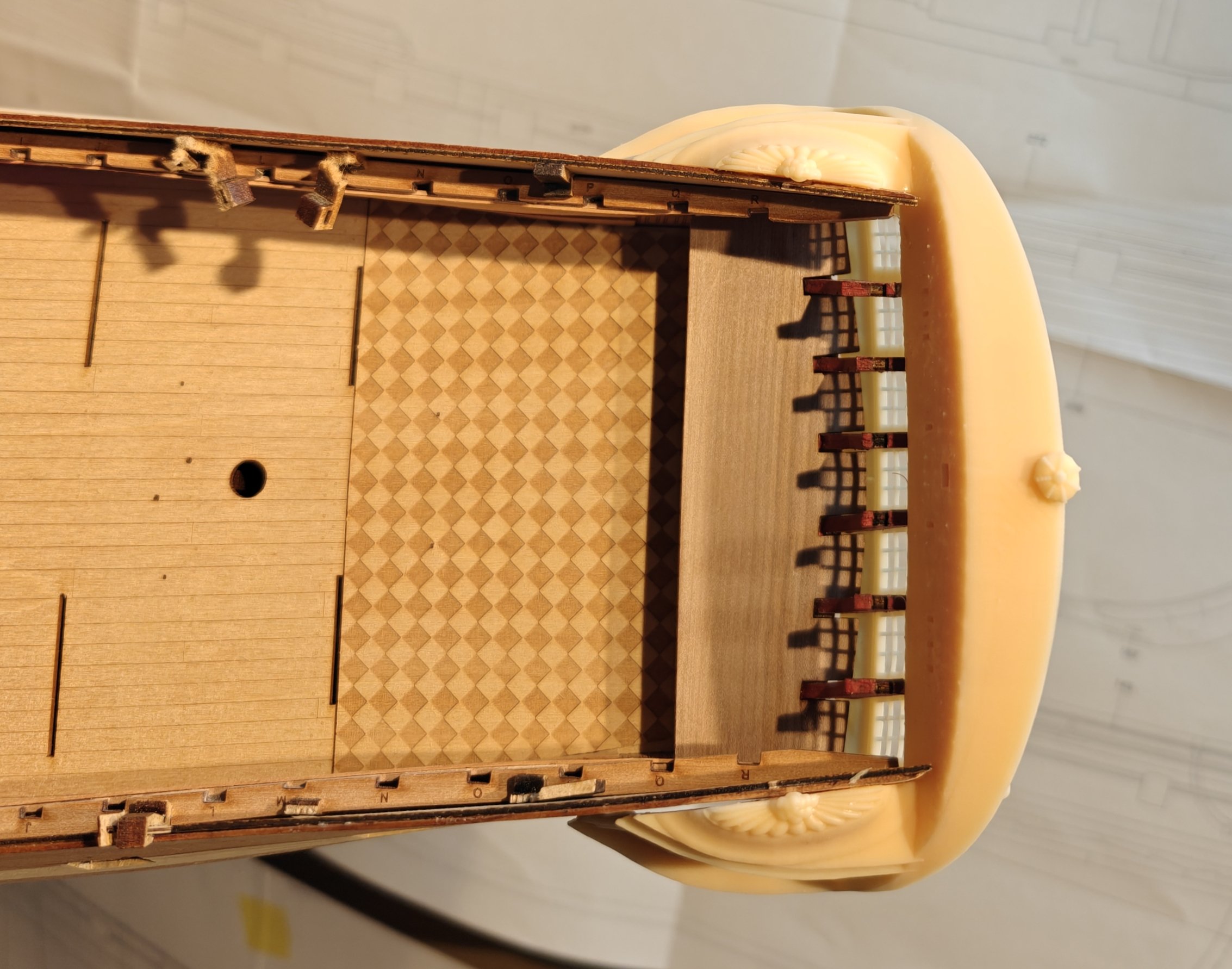
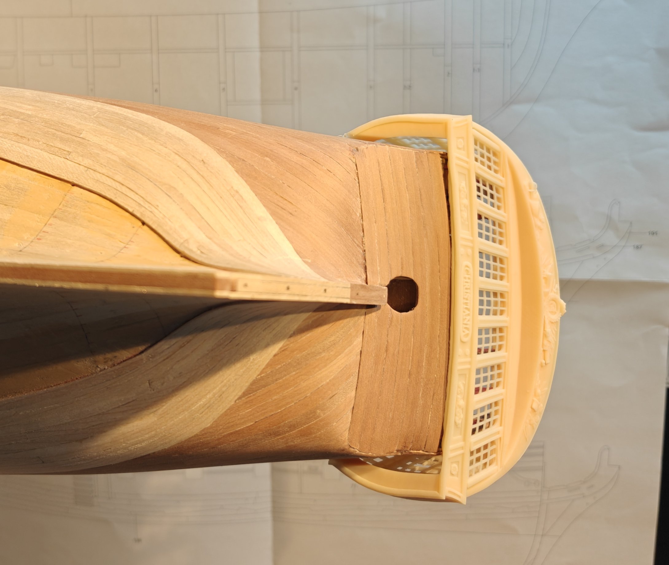
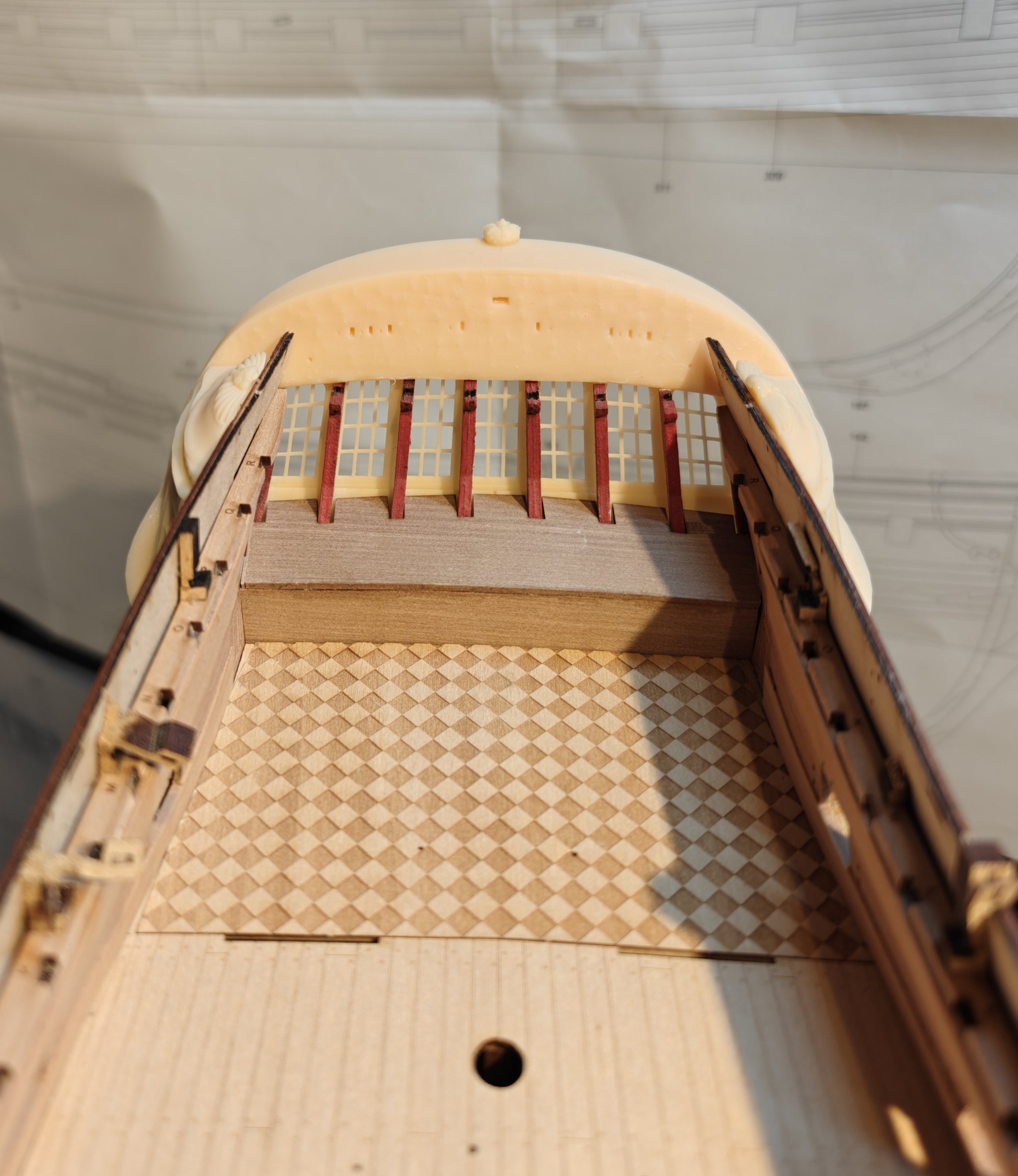
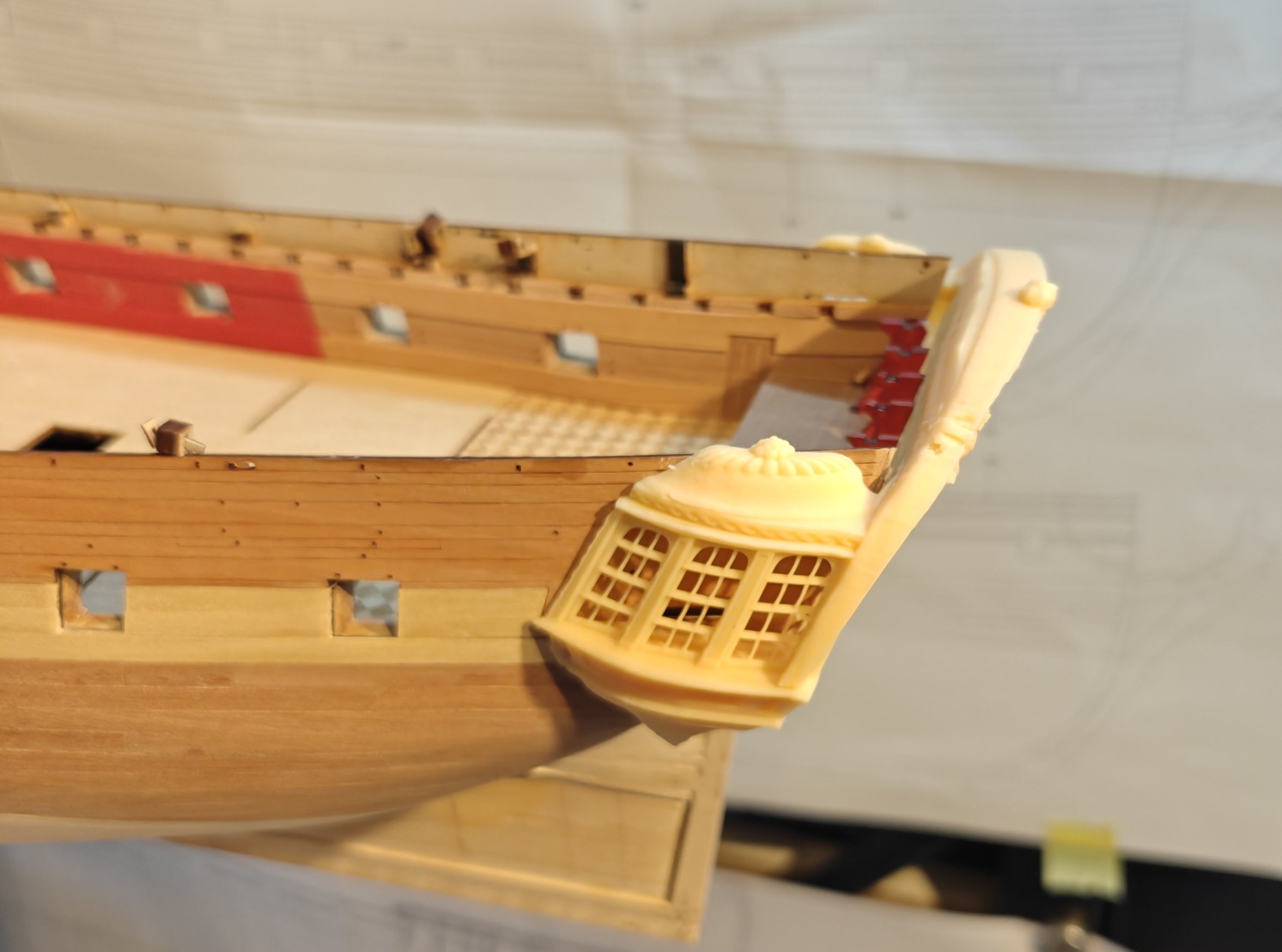
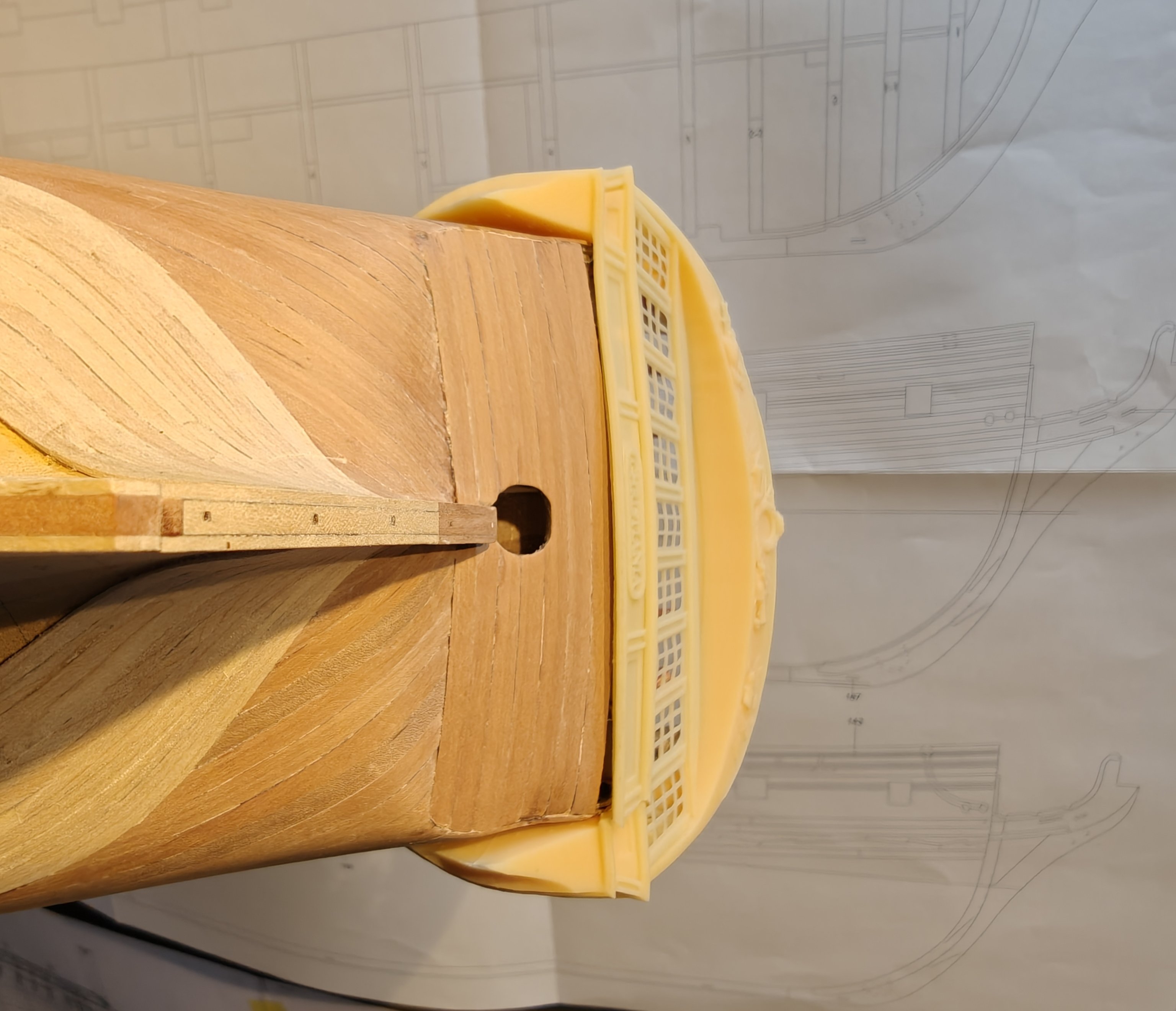
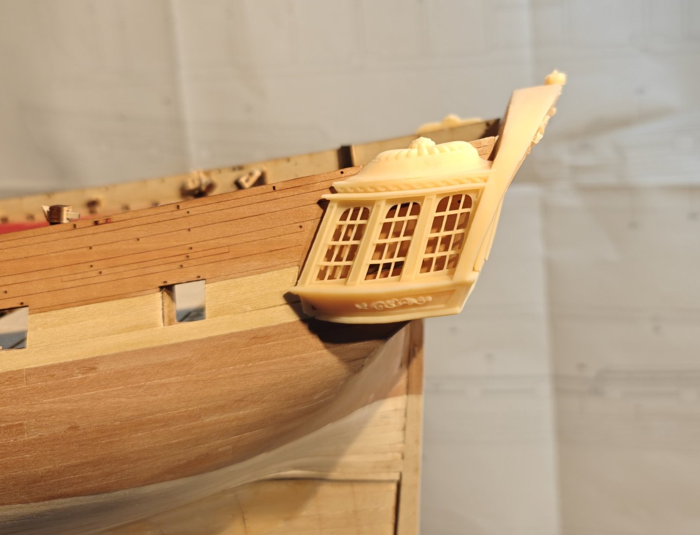
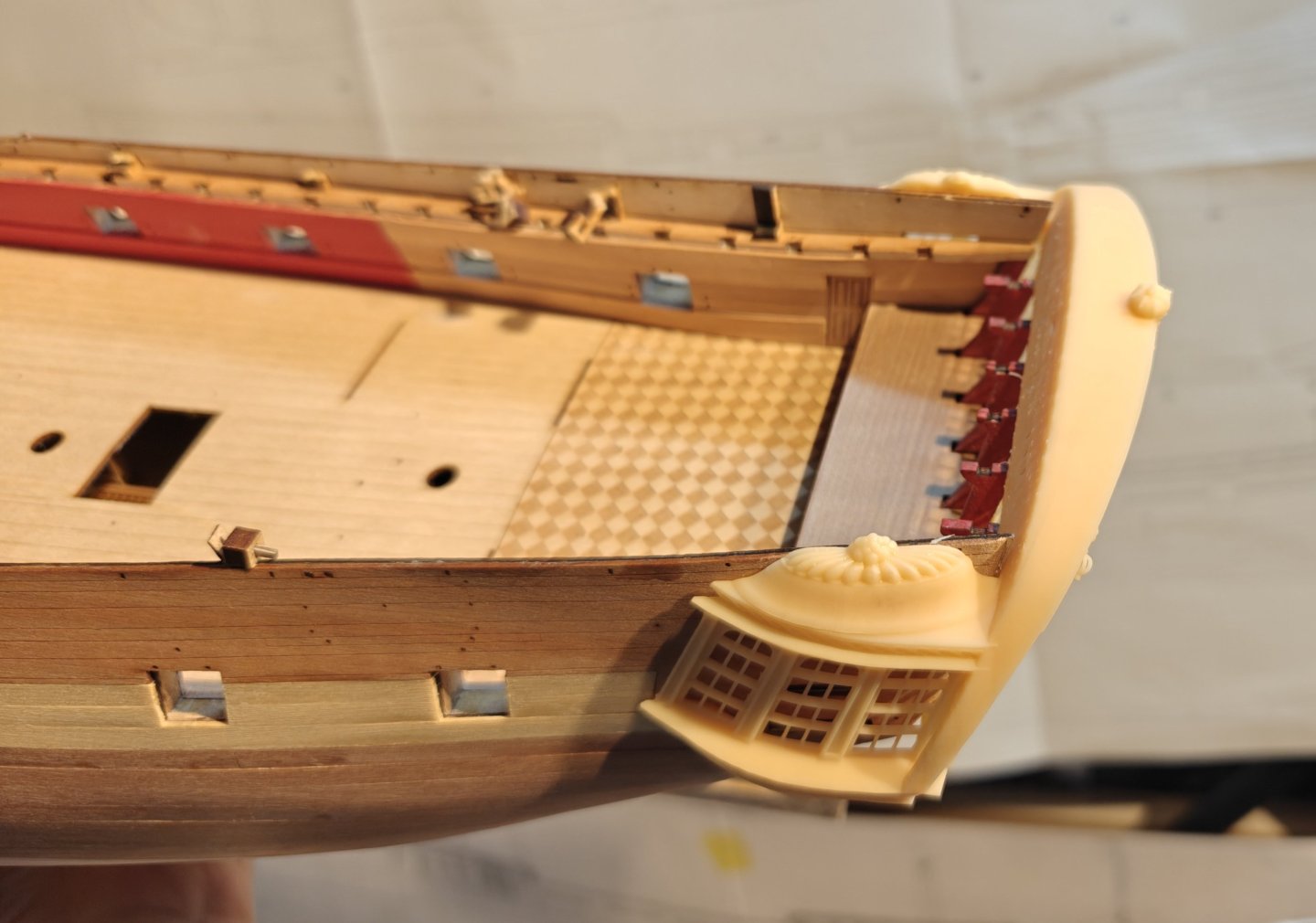
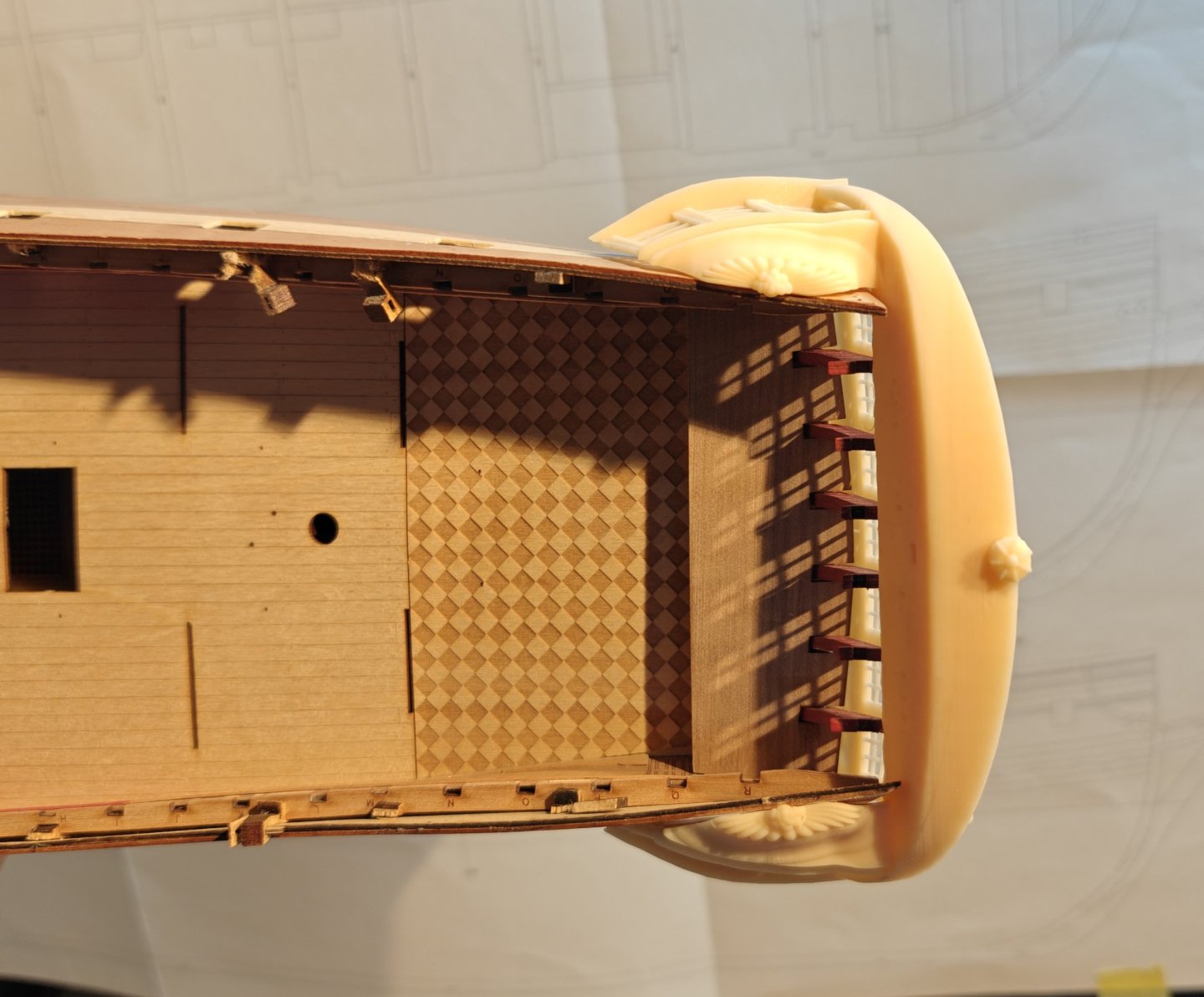
Log entry 29 - test print of stern I have tried to make a model of the stern that include everything in one part: windows, friese, side galleries, etc. I have a bit of issue with the print itself - I think I need to change the release film on the resin vat as I may have a tiny leak with a bit of cured resin underneath that blocks the light. Here is what it looks like: Overall, I am very excited to see this as it really shows what the stern will look like eventually, and I am very happy with how the different parts look. But... The fit is absolutely terrible 😅. Especially around the lower parts of the galleries. And the curvature of the rear window panel is also causing issues as the model is not a great fit there either. What I will try do do is this: re-model the rear window panel with a curvature and remove the lower parts of the galleries and make these separately or in wood to insure a tight fit. It will probably take a few more iterations to get it good enough, but I think I will get there eventually. BR TJM


- 148 replies
-
- 11
-
-
-
- Christiania
- Vanguard Models
- (and 1 more)
-
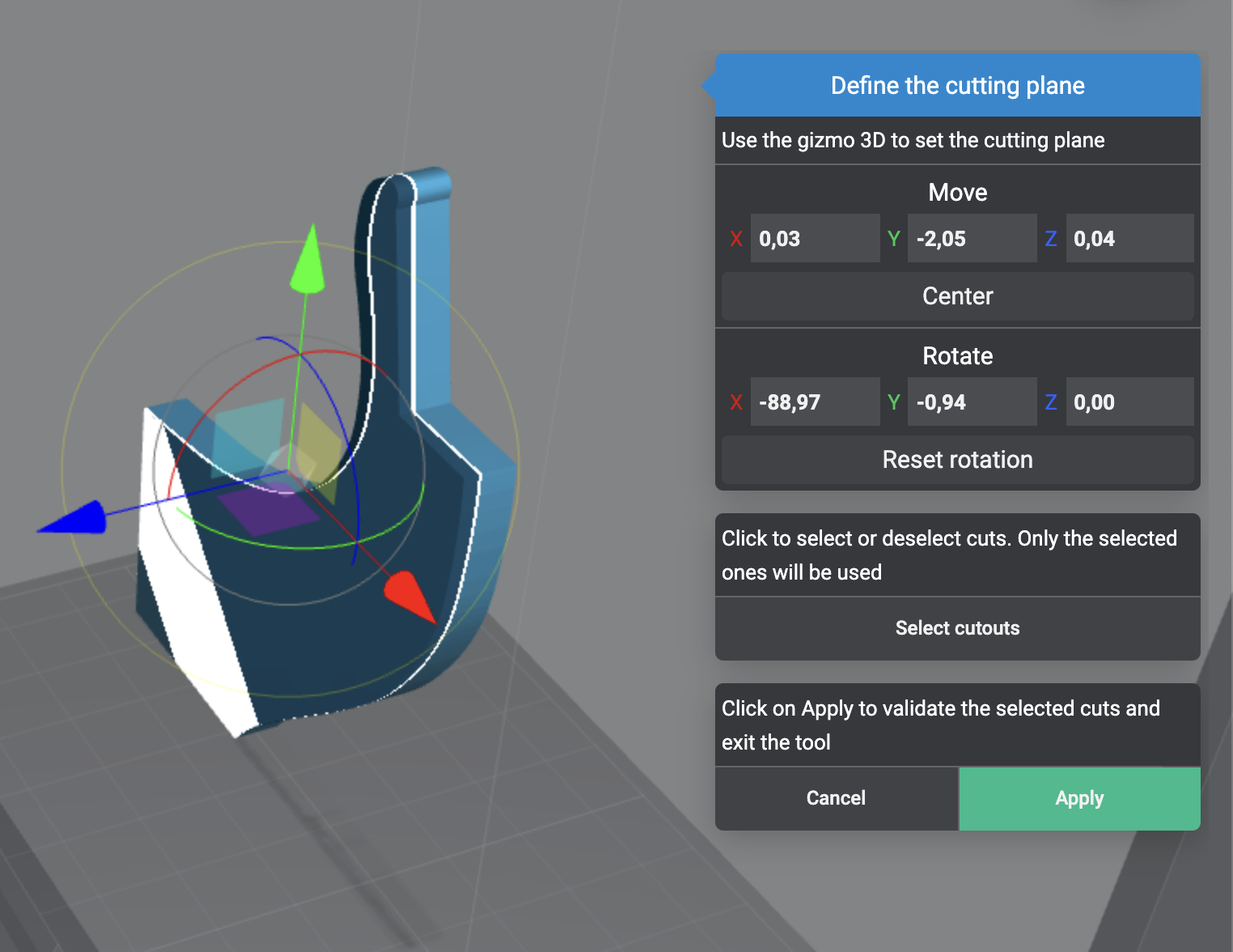
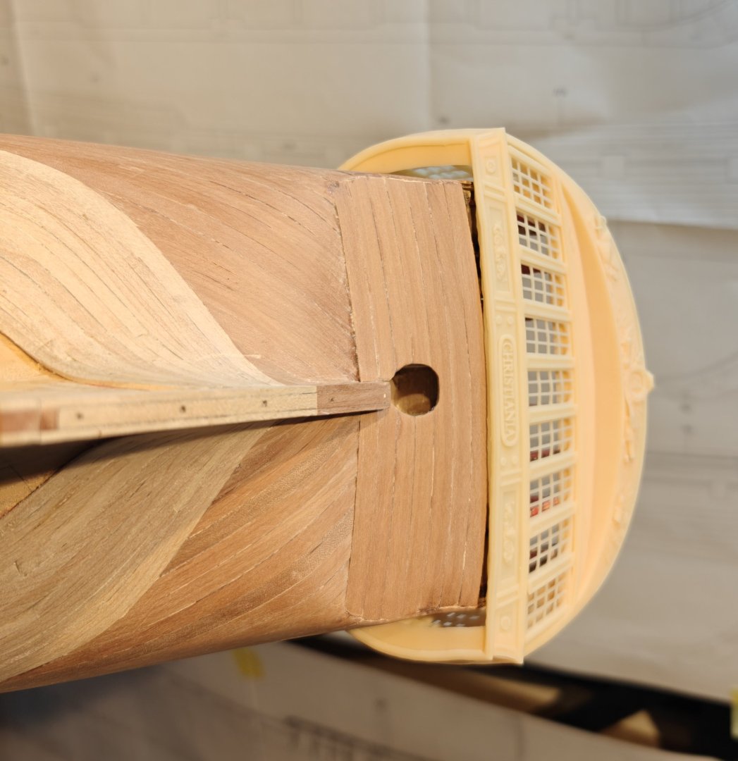
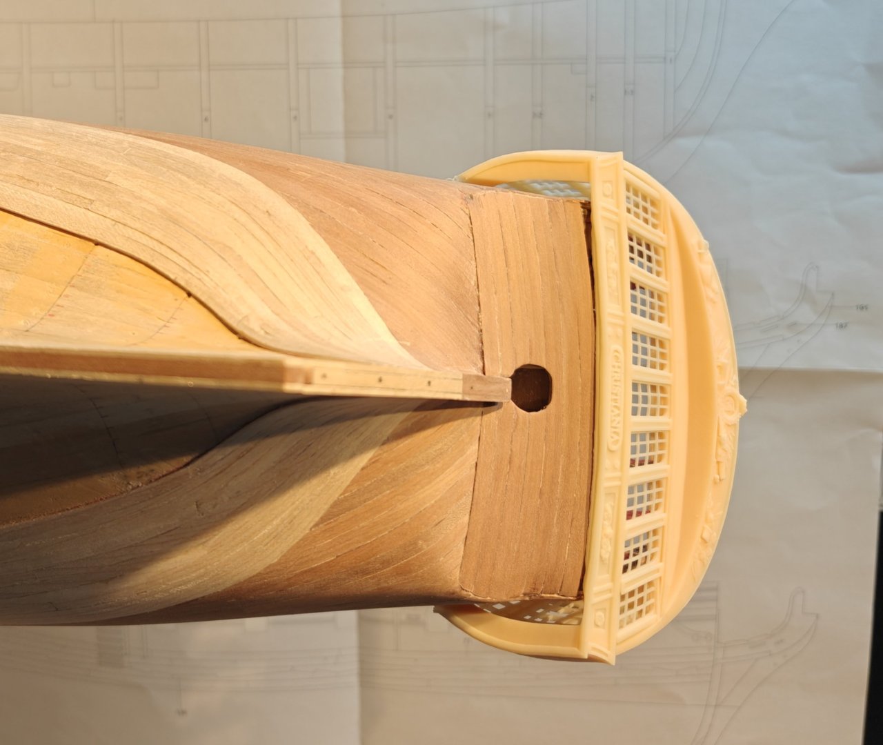
It is not a problem to make a taper like that, it is just two mirrored planar cuts to the 'tool' part. You can see an example from the slicer below and that there is around a 1 degree taper in two directions: Then you can get something like this: I am sure this is not completely accurate either, reality was likely more complicated. The accuracy will of course depend on how good your model knee is, but the procedure for the slot remains the same. I think it should be possible to make something that is good enough for a model with an aproximate 'tool' shape.