
TJM
-
Posts
362 -
Joined
-
Last visited
Content Type
Profiles
Forums
Gallery
Events
Everything posted by TJM
-
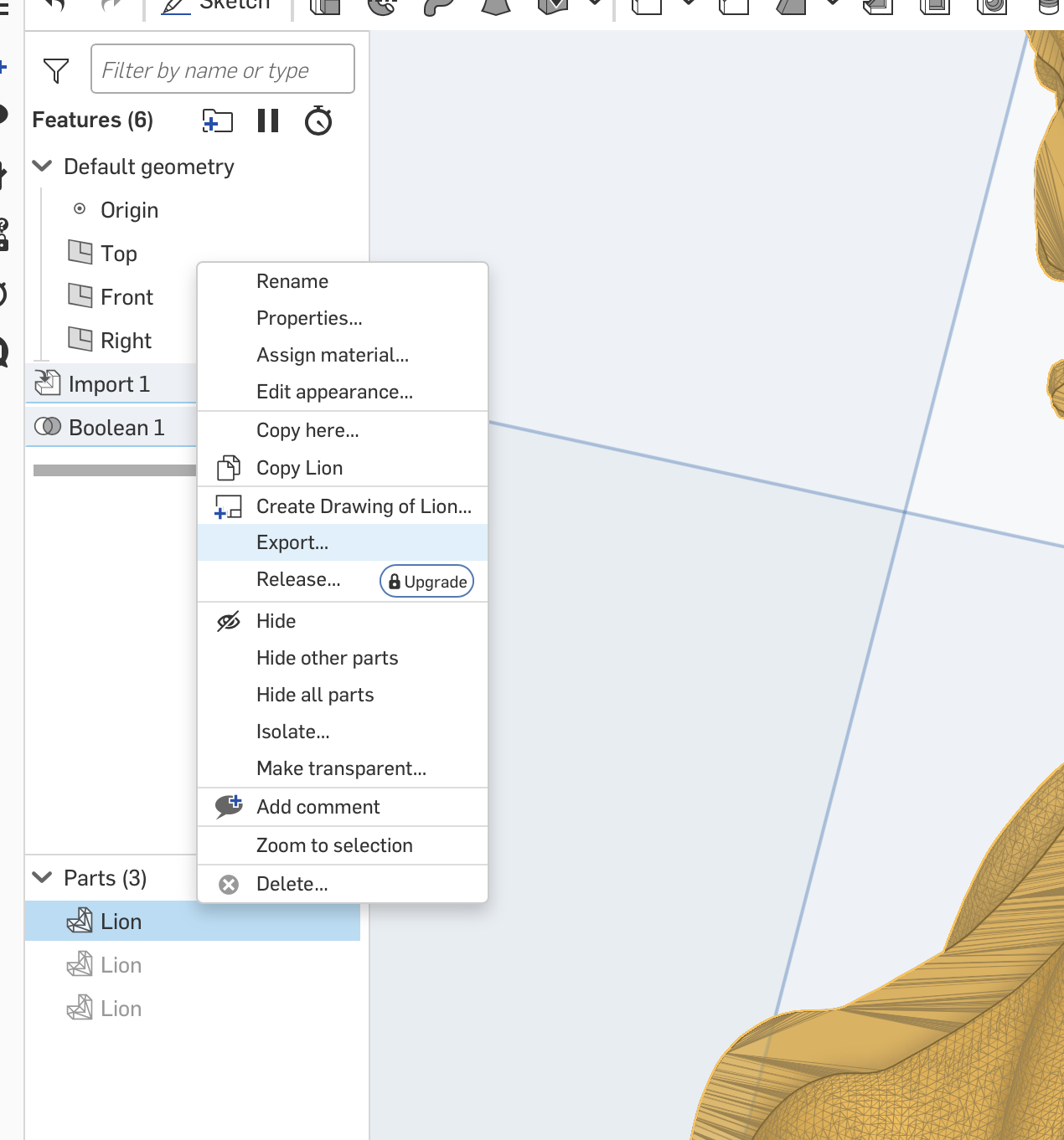
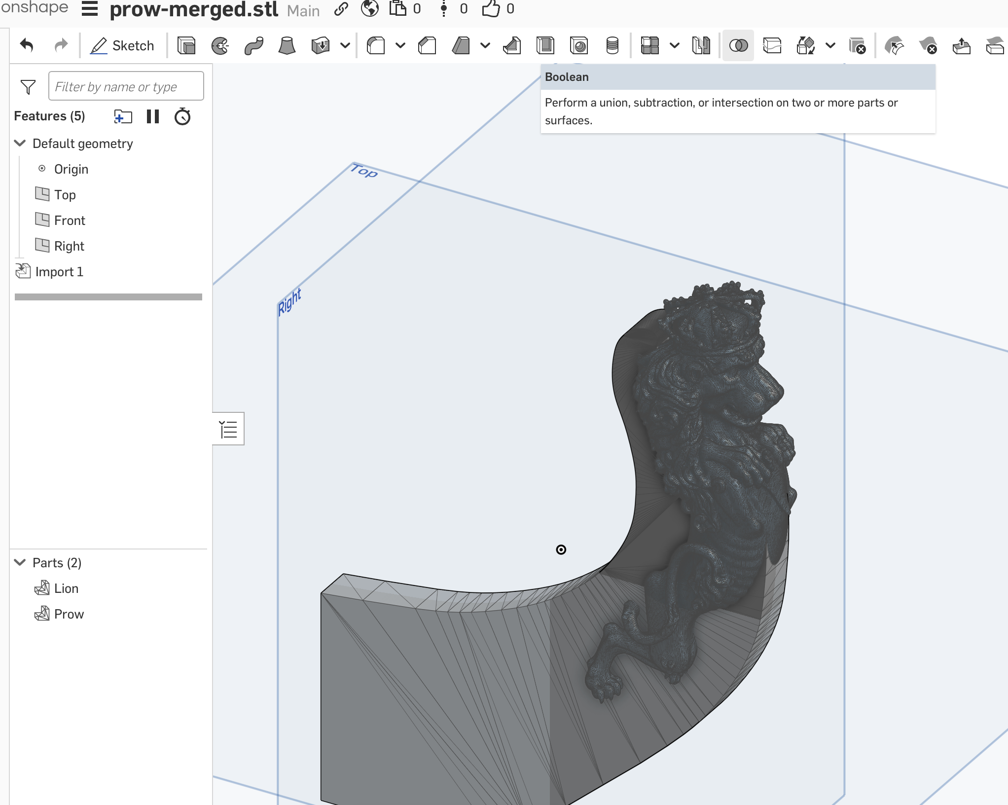
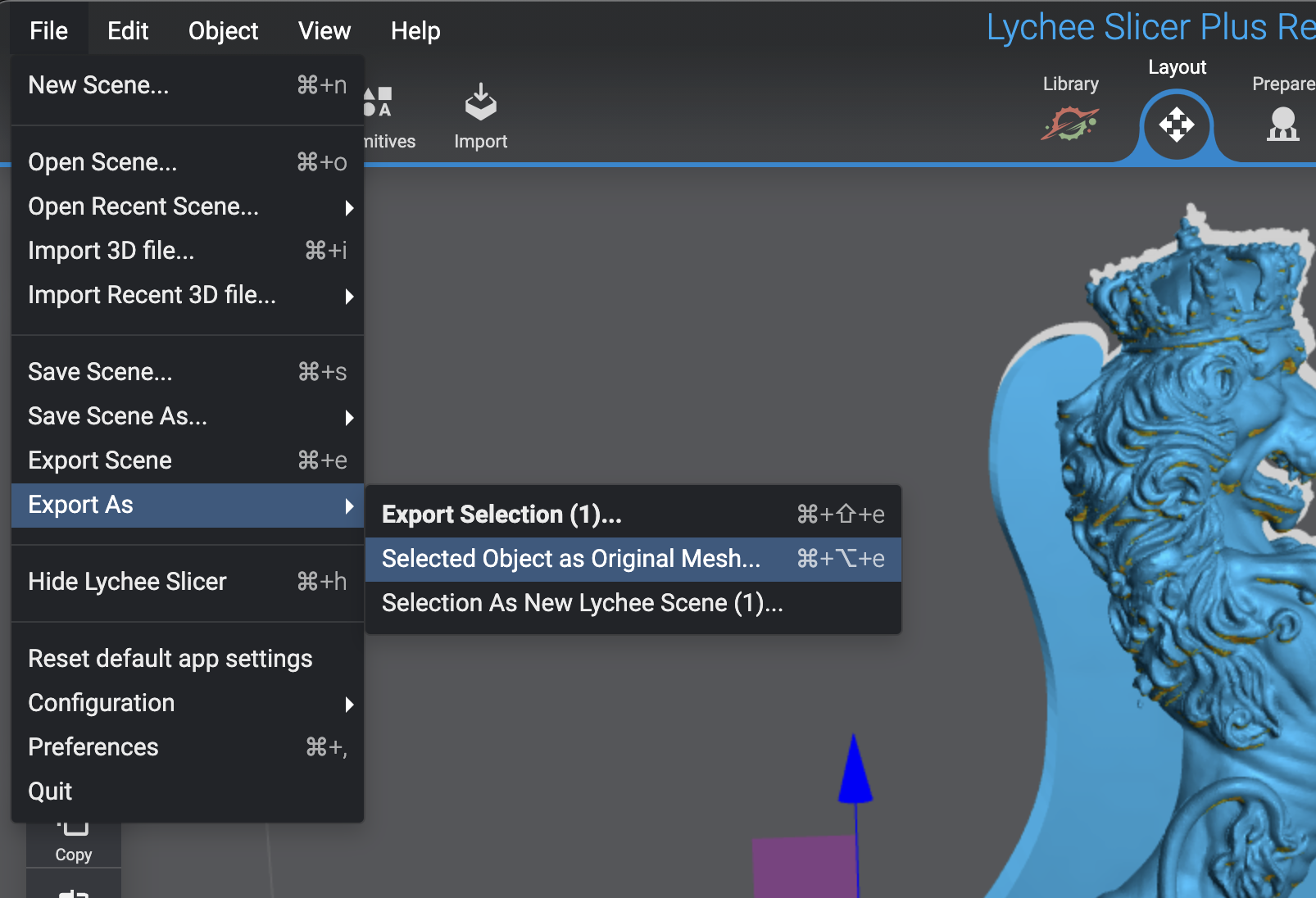
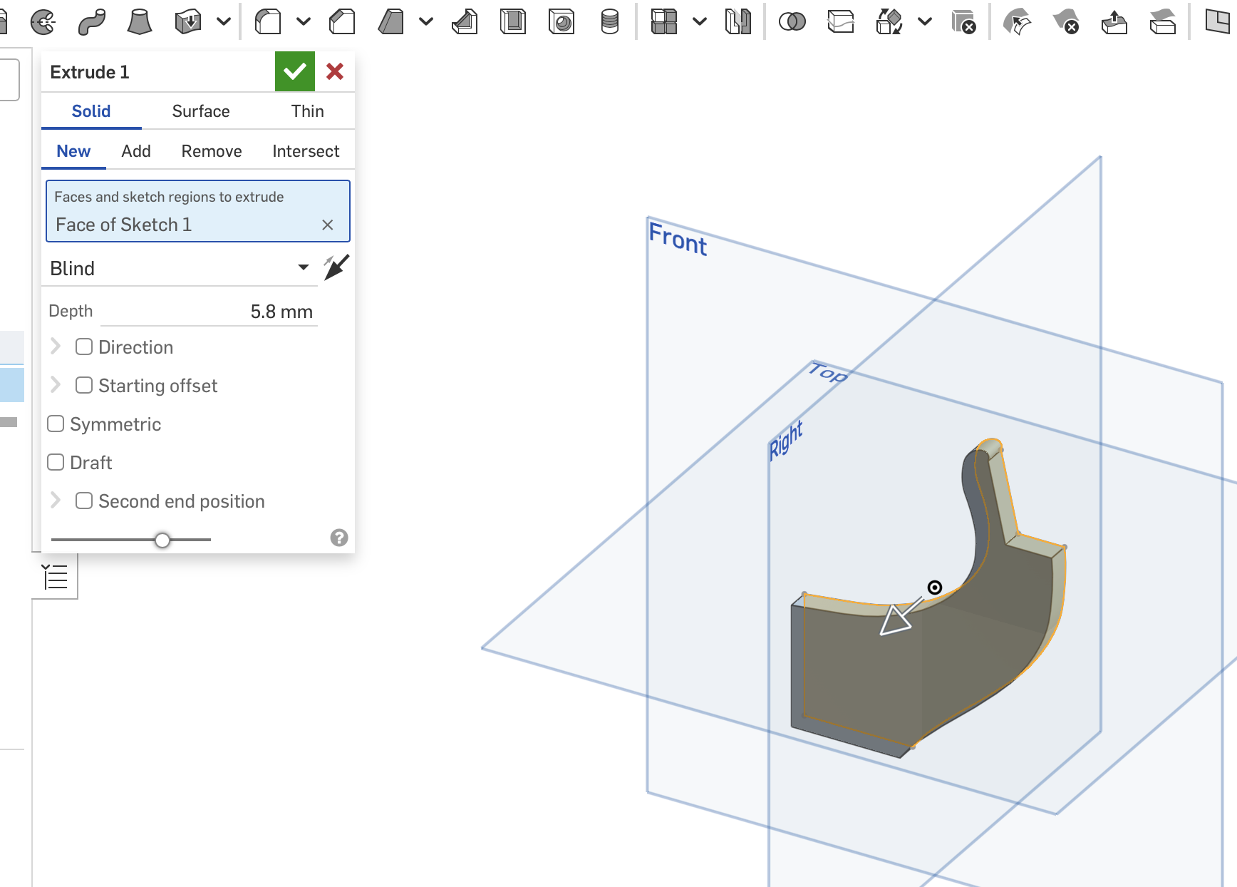
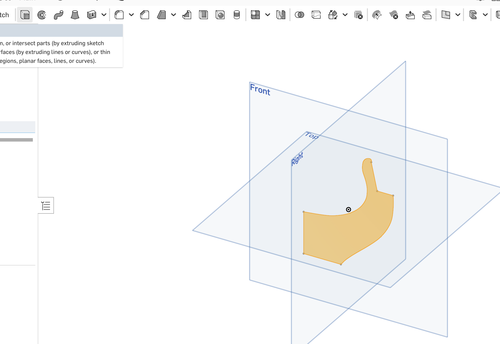
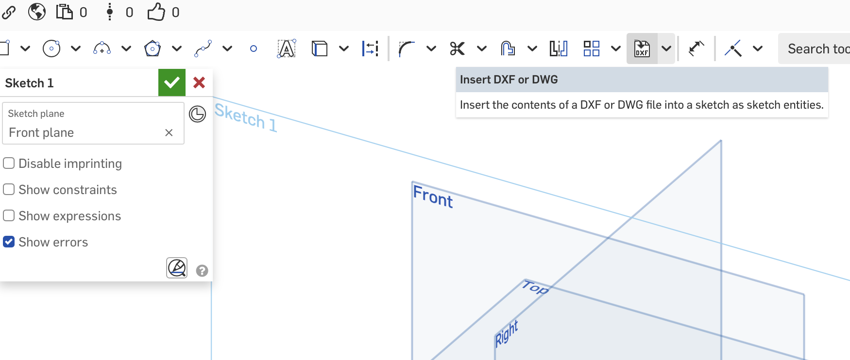
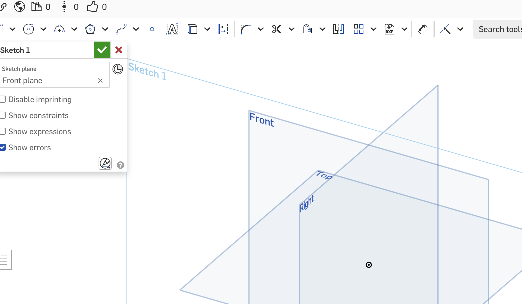
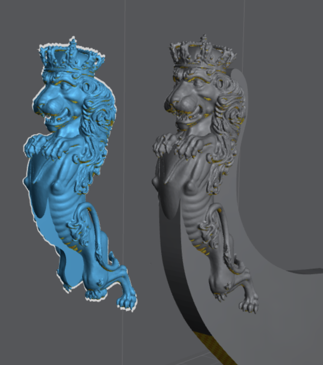
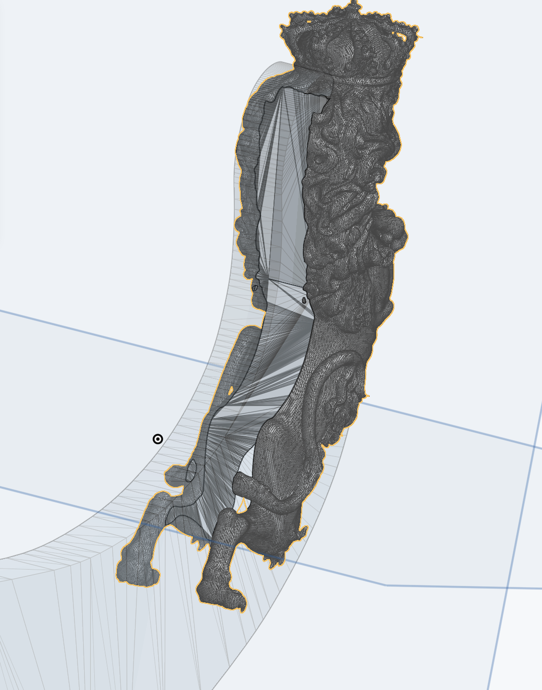
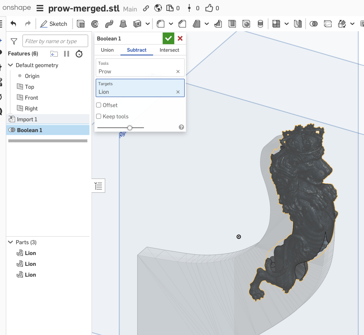
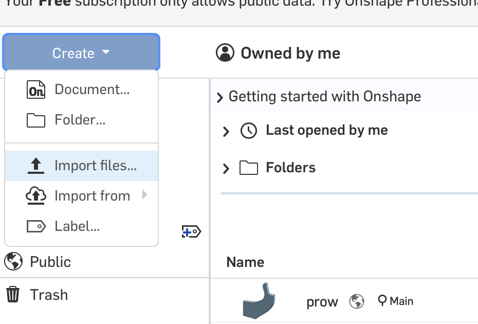
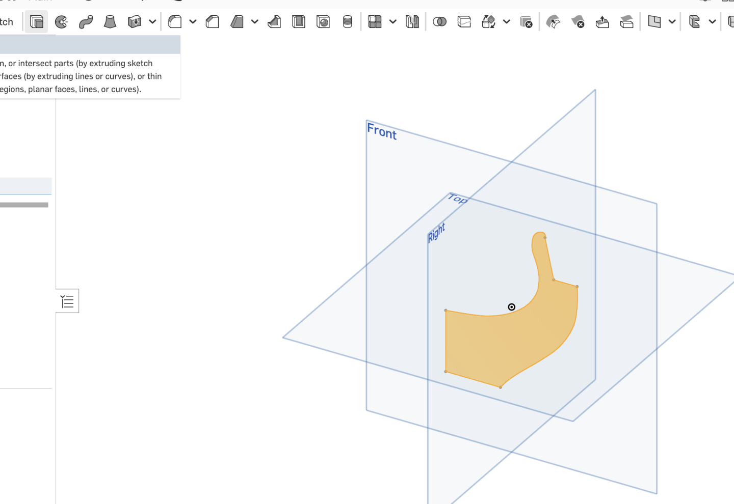
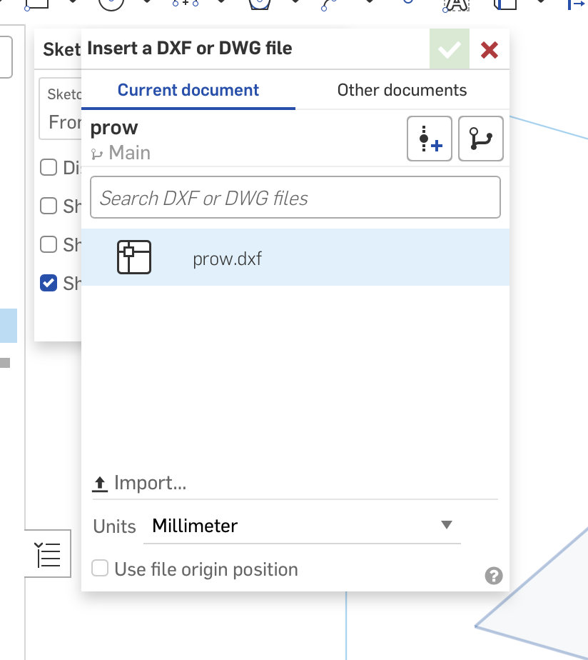
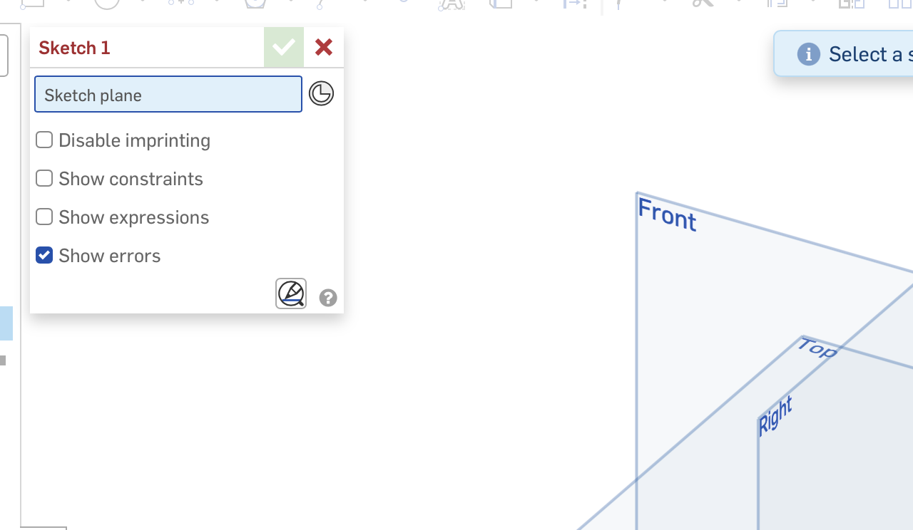
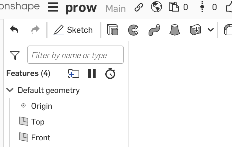
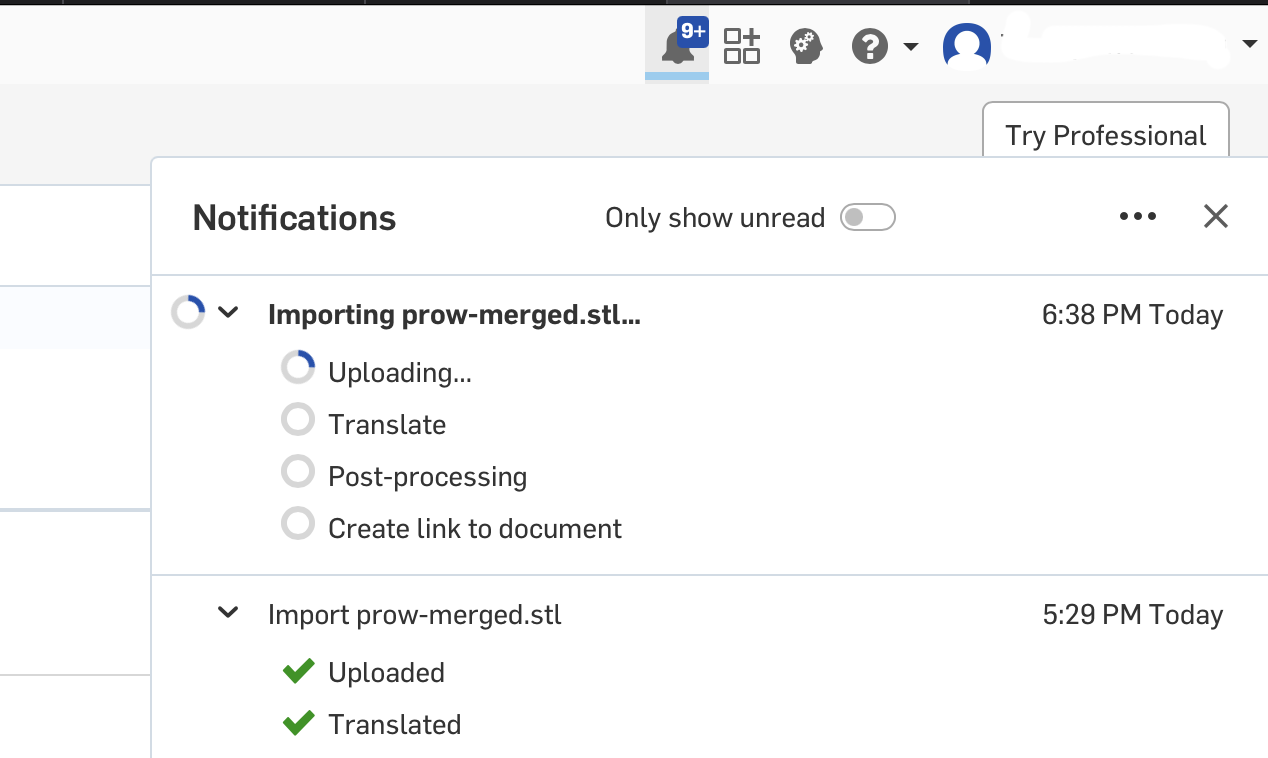
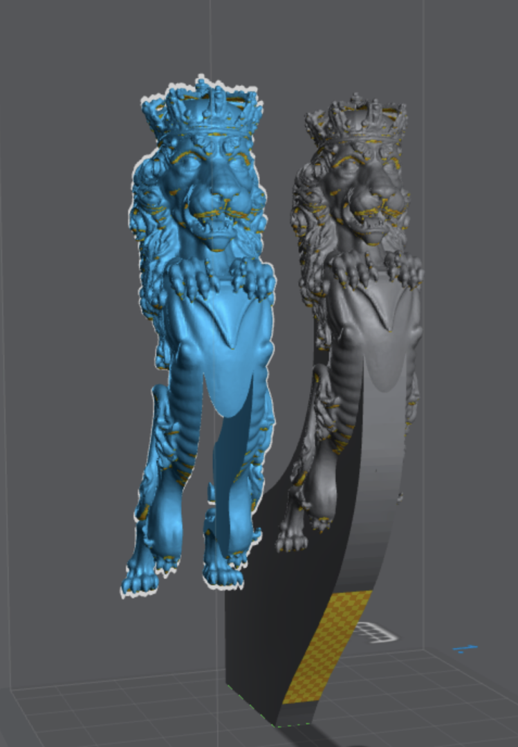
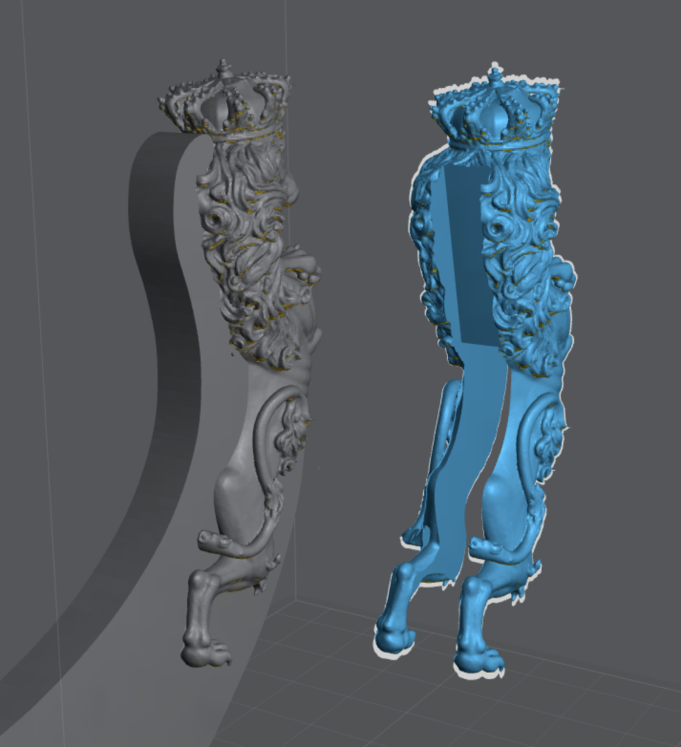
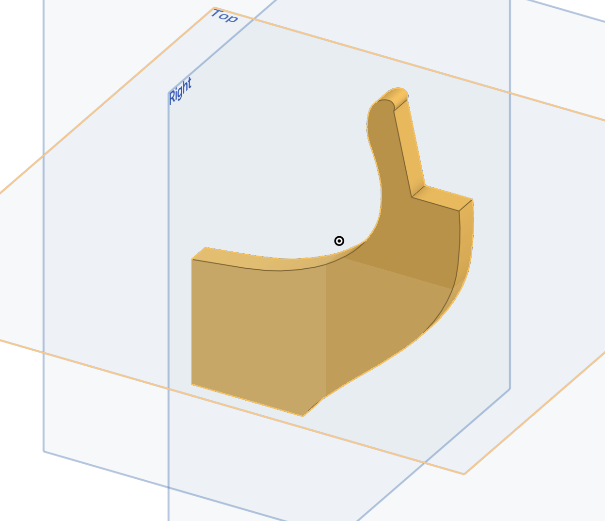
Alright, here's a detailed walkthrough of how to make the slot in the figure using Onshape: 1: make the prow template I am sure there are many ways to do this, but this is how I do it. I draw the shape in QCAD, using the scaled drawing as reference: You can do this in any CAD program. Make sure all the endpoints touch - it needs to be a closed shape to enable the extrude operation. Then I make a new project en Onshape and create a 'Sketch': You have to pick the plane to sketch on (I pick the front, it dosn't matter) Then, before completing the sketch operation, click the DXF function at the top right: Import your prow 2D CAD file: click the tick mark on the sketch function to complete this: Choose the central shape (not the lines) and use the extrude function (top left): Here you pick the depth to extrude, the thickness of your keel, but give it a bit extra, othewise bleeding of the pixels during 3D printing will likely make the cut to shallow to fit. You must experiment with the correct thickness. Then export this 3D keel shape as an stl: Import this and your figure into the slicer (you can do it in onshape as well, but I am not good at moving things around in that program, so I prefer the slicer). Adjust the position of the parts to fit and combine the parts (at least in Lychee, you have to do this to export both in the correct relative positions): Export the object to an stl: 2: make the slot with the boolean function in Onshape Now we need to import this model into Onshape. From the main menu, click the create>import Import your stl - the progress will appear in the notifications tab (a bit counterintuitive): When it is done, you get a link to your imported file: Now we are redy to do the boolean. It is at the top bar, two intersection circles icon: As it says, you can do three types of boolean operations, union, subtraction and intersection - we need to subtract. The prow is the 'tool' and the lion is the target. You can have several tools operating on several targets, if needed. In my case, three lion parts appear - this is because I have two small, free floating bits of mane - normally you would just be left with one slotted figurehead part: Then you just export the part(s): I have seen instances where the boolean function fails - this happens if there are very extreme topologies as a result of the subtraction, but mostly, if you have so-called water-tight stl files, this just works like a charm. Let me know if there are any points that need clarification! BR TJM


-
If Chitubox can do this with non-perfect stl's, that might be easier! The repair was the biggest challenge for me. I will still post the step by step using Onshape though 🙂
-
Yes! I will do a step by step with more detailed screenshots. Stay tuned!
-
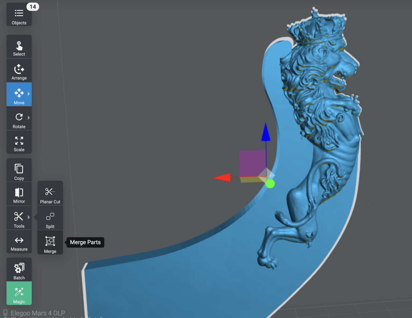
I also don't have any skills with the likes of Blender and Z-brush, but I have found a workaround that makes it easy to make the slot it the figurehead: I draw the shape of the prow and extrude it to the correct depth: I then import it into my slicer (Lychee) along with the figurehead and position them. I find it is much easier to work in the slicer than in a 3D CAD progam when manipulating the part positions: I then merge the parts and export a combined stl. The file actually still contain the seperate parts, which is detected by the next program, Onshape, a free online 3D CAD program. The prow is then subtracted from the figurehead with a boolean operation: and the final slotted figurehead can then be exported and re-imported into the slicer for printing: This all takes 10 min total - except that the original file produced by meshy has topological errors. They are fixable to a sufficient extend in the slicer for the purpose of printing, but that is not good enough for the high tolerances of the Onshape program, so it is nessecary to repair and re-mesh the original figurehead file before this simple workflow can be completed. And that took me a bit of time to work out! I used a free Autodesk program called Meshmixer to repair and re-mesh the model here. So provided that you have 'water-tight' stl files, making the simple geometric subtraction to get a slotted figure is relatively simple, but it took some work to get there! I have attached the slotted file here as well. BR TJM Grønland figurehead cut.stl


-
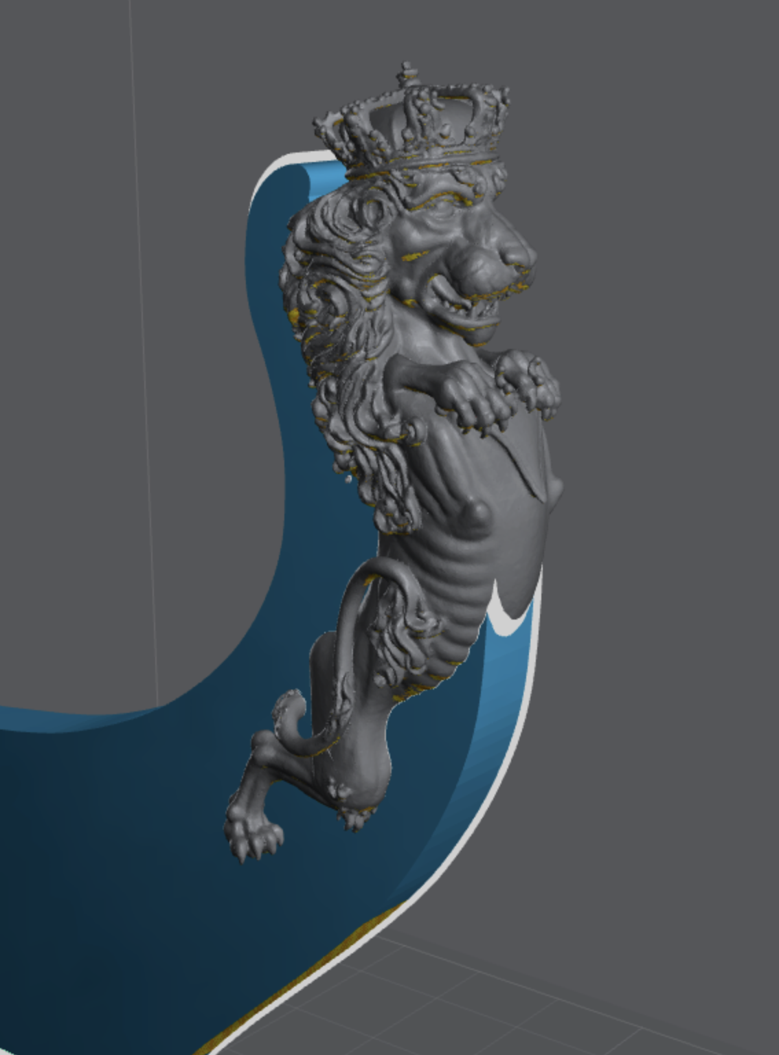
Sure! I ran it a few times, and they are all really good, but all have a few minor issues - some will be easier to fix than others. This one has a little thing sitting on the hands and it has the tail mirrorerd on both sides. But even with these small shortcommings, I am sure it is workable with a few tweaks! FYI, this is the figurehead for the Danish 50 gun Ship of the Line Grønland (Greenland) from 1756. Grønland Figurehead.stl
-
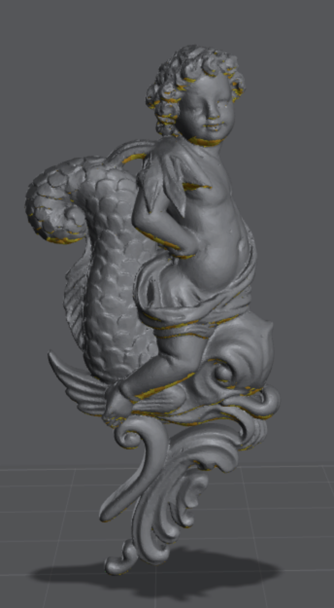
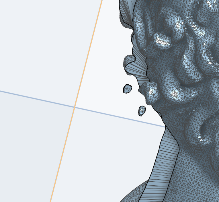
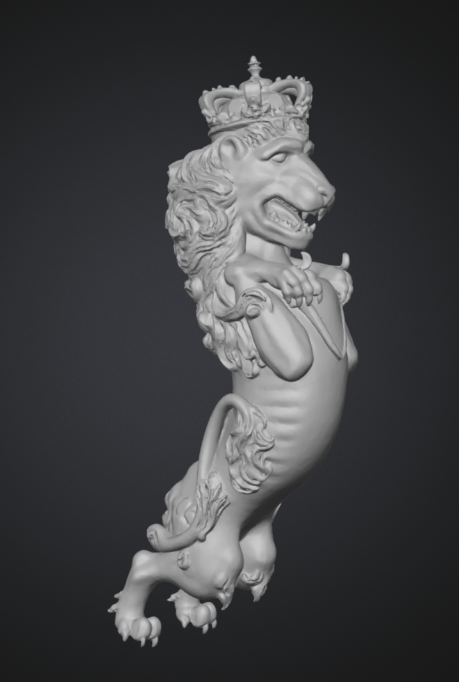
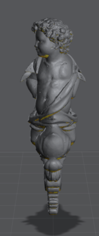
This is truly an incredible leap that has hapened in the last few moths with the latest AI models. I tried a few examples of using original construction drawings to get figurehead stl's and I am blown away. Heres a 'standard' lion: To me this is crazy! All I did was take 5 min in photohop to remove everything from the drawing that was not part of the lion, fed it to meshy and voila! And here is a non-symmetrical one where it had to extrapolate the left side: You can see that there is not really much to go for in terms of detail, especially in the face of the cupid, but look what I got from the model: For a 3 cm tall figure, this is going to be all fine. Basically, this was the last big nut to crack for me in my effort to design ships from the original plans. Lot's of learning and experience still to go, but the tools are here now. I am really amazed. Thank you chuck, for pointing out that AI have come to this point now! BR TJM


-
I have an Elegoo Mars 4 DLP. Small, but good enough for most parts we are interested in. And since it is a projector, as opposed to a LCD, I don't destroy the printer if I have a resin spill. But beware of the safety aspect of resin printing and the need for a dedicated space with good ventilation and room temperature!
-
Wow! This is fantastic! I have tried to do this with various apps, also the free version of Meshy, but were not able to get anything useful. I will definitely dive into this again! In any case it is just a question of (short) time before this will be possible from even worse reference materiel. Thank yo so much for exploring this and posting it here!
-
Ok, I made a print yesterday and in general, it turned out really nice. I printed two with grating and two without, but one of those with failed. A few observations: I should probably use slightly thicker planks. 0.4 mm is very thin (and see through!) 0.6-0.7 mm is probably better. There is a bit of cavity under the deck planks. Cavities with no drain is a big no no in resin printing. Technically these are not closed off, but it seems the openings are just a too tight here. You can see a bit of seepage around the openings. The solution is to fill out all the volume under the planks or make the gaps between planks a bit wider. I do think everything is so thin that I am able to cure everything, but it is not ideal as is. This is close to the largest object I can print. Including supports, this was 136 mm tall and I only have 150 mm total. Without rudder, I can go up to a boat of max 30 Danish feet. This was 2700 layers and it took a full 12 hours to print! However, each boat, including supports only consume 10 ml of resin 😄. If I can fit in wood grating, I think that will be the better option, though the 3D printed one is ok. All in all, I would say this experiment was a success and a good proof of concept for future ship boats! At some point I will make the 20 ft Jolle and a 23-28 ft Challoupe for Christiania as well.


- 148 replies
-
- 10
-

-

-
- Christiania
- Vanguard Models
- (and 1 more)
-
Thank you @Thukydides! I think I got lucky and that my methodology just happens to 'work out'! I also think it helps that I am doing this on a plank by plank basis, as compared to making a surface that hugs the whole of the hull in one go. Here's an example of a plank of average complexity in terms of topology on my boat: Firstly, the planking runs are determined already in 2D CAD based on the lines from the original drawing (with my crude extrapolations on top): In hindsight, I should have been more carefull, especially around the upper 4-5 planks and made some smoother help lines. This would have avoided the slightly wonky run of those planks, but when I discovered it, I was quite far and it would have meant starting over, as all the frames would need to be altered. Here is a look at the surface that will form the 4th plank from the top: It is quite extreme and a lot of it will need to trimmed away. I found that the shape only worked when I had fixing points at the keel (the rabbet?). After this, I made two 'limiting' surfaces where the plank edges should be. I use the klinker shape of the frames to make the perpendicular surfaces: After extruding the two help surfaces, they are used as tools in the subtractive boolean operation, removing the unwanted part of the plank: This leaves just the plank in the correct shape, but it is quite tedious to do, and for some of the surfaces, I was getting close to the limit of computing power in Onshape, as it was getting quite slow! After repeating 12 times, I got the 12 planks, in the correct position, faired against the frames. I should mention that when thickening the frames, I extruded 0.1 mm outwards and 0.3 mm inwards. This means that non-faired nature of the frames gets covered in the plank thickness, and that any micro-protusions of the frames through the surface gets covers by the outward extrusion. I hope this makes some sort of sense! I basically have no clue what I am doing and I am lacking some vocabulary/teminology to properly describe the process, I just try until it seems to work!


- 148 replies
-
- 4
-
-
- Christiania
- Vanguard Models
- (and 1 more)
-
Log entry 28 - a 25 ft 'Barkasse' Hi everyone, Wow, progress is slow for me at the moment 😅. Vacation, covid, other commitments, etc. has meant that I have not managed to progress with the actual ship since last time. But I found myself exploring a particular rabbit hole: would it be possible to make acurate ships boats for the model? Many of the drawing sets at the Danish National Archive includes drawings of ships boats, and there are two for Christiania, a 20 ft 'Jolle' (=Yawl) and and a 25 ft 'Barkasse' - I believe the english equivalent of this is the launch. I think it is likely the ship also carried a 'Challoupe' (Pinnace/barge), but there are no drawing of a challoupe specifically for Christiania, but they are the most prevalent class of ship boat in the archive. The Barkasse, is very box like ('kasse' = box - perhaps a coincidence, pahaps not...), more so than the English launches, so I decided to try to model this for 3D printing! a bit daunting, as I was just figuring out what worked as I went along, but I am happy with the end result. This is the original drawing (G312): There is also a sail drawing, but that is not so relevant for my use case. First, I drew the frames and keel acc. to the plans (at 1/64 scale): This was done in QCAD. I have prepared the frames for klinker planking - I know the English launches were caravel/cravel planked, and this might have been as well. However, all the drawings in the archive shows all boats, regardless of type and size as cravel planked, and I am pretty sure many were klinker planked, so I decided to do this as I like the detail that it gives on the hull. After this, the parts were brought into Onshape (free onling 3D CAD program) and extruded to the correct thicknesses. Then I aranged the frames on the keel and started making point-constrained surfaces using the plank section of the frames. That creates a surface thatcan then be extruded, but while it covers the plank in question, it is over-large and need to be 'trimmed' to the correct plank shap. This I did with two boundary surfaces which, when extruded to a 3D shape, can be used to trim the plank to shape (with a boolean operation). Then I repeat that for all 12 planks. This was the difficult part - planking the hull - and then it is easy to make the other elements in a similar fashion, drawing and extruding the parts and adding them to the model. This is the final result: The planking looks a but rough in a few places, but bear in mind that the model is really small: the overall lenght is 123 mm and the thickest part of the planks are just 2 mm wide! The grating holes are 1x1 mm. I have no direct evidence of how the grating and deck should look for this particular boat, so I have made a more or less generic interior. While the drawings do not show it in this case, there are many drawings of 'barkasser' in the archive that shows mountings for swiwel guns in connection with the heavy cross bracing fore and aft. To add a bit of interest, I have added this feature to my model as well. The drawing also does not show the rudder, but I have used a rudder shape from another (larger) barkasse from very close to the same year as Christiania - this is hopefully a resonable approximation. At the very least, I will make the seats out of 1 mm pear, but I may also make the grating out of pear. I think I will print a version with and without the grating and see what works best. The blue sections in the image below will as a minimum be made of wood: The very tiny oar 'pins' will not be printed, they are just to small at 0.2 mm thickness. I am not 100% sure this is actually what they looked like, or how they are supposed to work. Some drawings show what might be a small eye ar the top, so perhaps a loop of rope was attached to keep the oar in place? If anyone knows how this type of oar rest worked, please share! Now I look forward to seeing how this prints! And then I think it is high time I finished that planking so I can continue with all the interesting bits that comes next! BR TJM


- 148 replies
-
- 8
-
-
- Christiania
- Vanguard Models
- (and 1 more)
-
This is so great! I really look forward to seeing them fully painted and rigged! When I have the time, I will start a thread on the 3D printing sub-forum where I will post stl files for Danish canon, in case someone else might want to go down this particular rabbit hole at some point 😅. I have a whole series from 3 to 36 pounders from the 1740's-1750's, but I am also looking into earlier designs from the 17th century and later ones from the end of the 18th century
-
Couldn't this be a consequence of 300+ years at the bottom of the sea? Do we know for sure that there was such a misalignment when the ship launched?
-
Fantastic work!
-
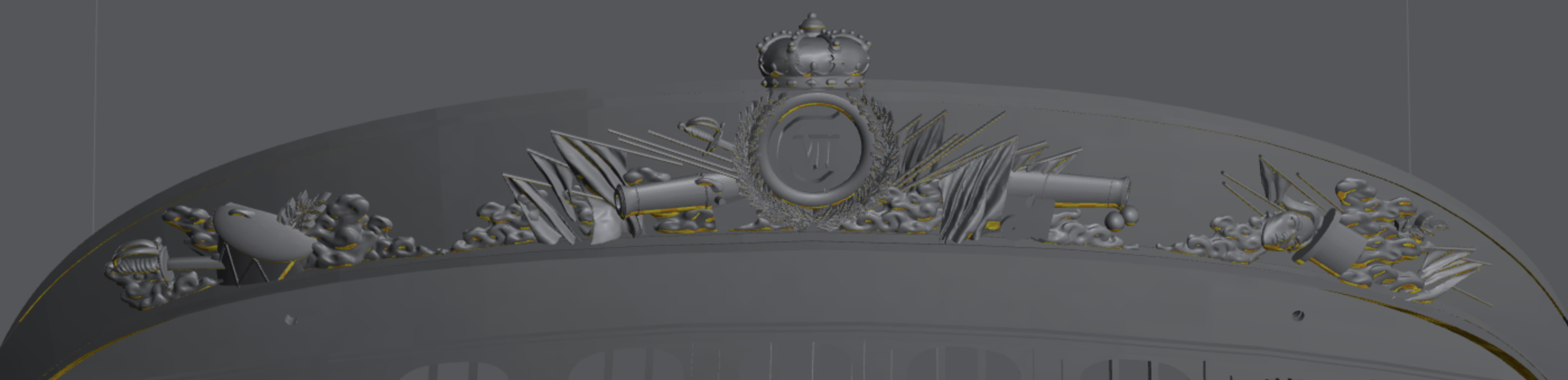
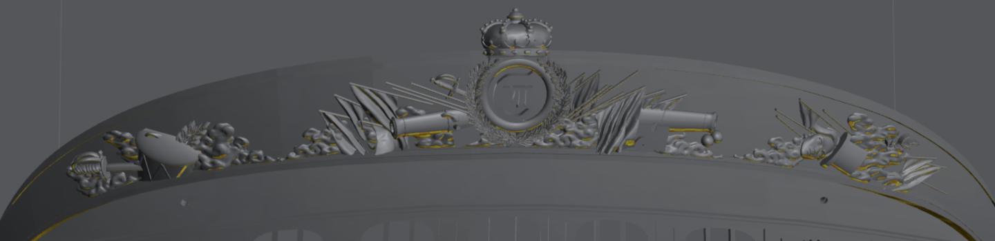
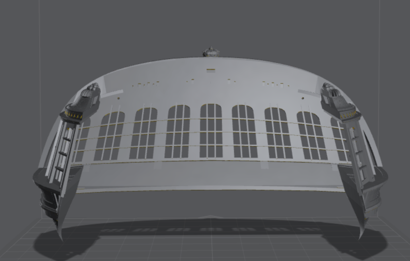
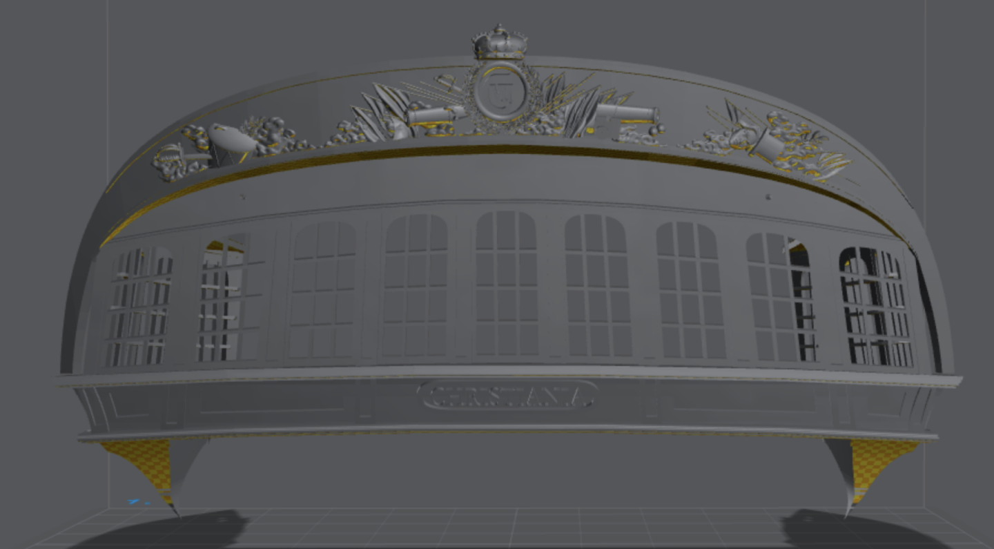
Log Entry 27 - modelling the stern friese I am still working on the fit of the quarter galleries, but as I decided to remodel the friese in actual 3D (not just a raised relief/projection), I have been working on that. I am very happy with the overall shape and together with the galleries, it is really shaping up now. There are still some rough spots at some of the joints between parts, and I think I will print the stern and side galleries seperately, and then some of the ornaments are still missing (tiny lion heads I and som garlands, flowers, etc. ) It will take some more (probably rather difficult) work to get it to the final shape - I may print a test version at some point to se how the fit is. I find it very satisfying to see the whole thing in 3D, but I also find that the dimentional accuracy of the resin printing is not super good for large parts, both due to uncertainty in the z-axis (layer thickness) but even more the warping flat parts. Over such large pieces, you quickly more a milimeter or more from the target and that makes it very difficult to fit onto the model in a prcise way. So I think I basically have to iterate with a buch of trials, which is quite tedieous with the resin printing process! We'll see how it turns out in the end 🙂 BR TJM
- 148 replies
-
- 8
-
-
- Christiania
- Vanguard Models
- (and 1 more)
-
Ok, I made a quick edit of the roof and here is a comparison: the previous version on the left, the new one on the right: The new one looks much more natural, with the lean towards the stern. Thank a lot for pointing this out Matthias! In the end, the change took just a few minutes to do, so very much worth it! This version is also a bit re-scaled (the comparisson on the left is as well) compared to the print I made, so I will try this one and see if the fit with the hull is better now.

- 148 replies
-
- 6
-
-
- Christiania
- Vanguard Models
- (and 1 more)
-
Hi Matthias, I see what you mean! Dome of it is due to the perspective, especially in the last image, and som of it is due to the way I made the roof. The thing is, the QG area is largest at the rear, so I have stretched the shape in that end to cover more of the area. Snd conversely, I need it to be compressed in the forward end, to make it fit the shallow roof there. Unfortunately that gives an impression of leaning forward a bit, from some angles. I am contemplating if there is anything I can do a bout this - perhaps there is. My problem is that I cannot stretch just the top part backwards with the simple tools I use, but I will see if I can find a workaround. Thanks for pointing it out to me! BR TJM
- 148 replies
-
- 3
-
-
- Christiania
- Vanguard Models
- (and 1 more)
-
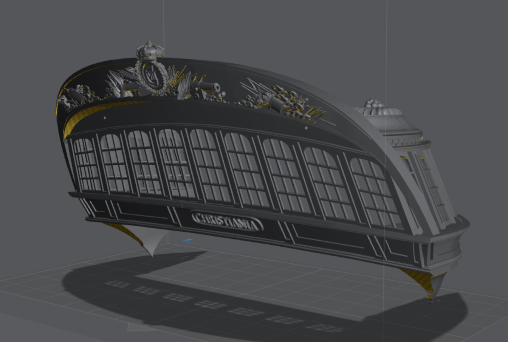
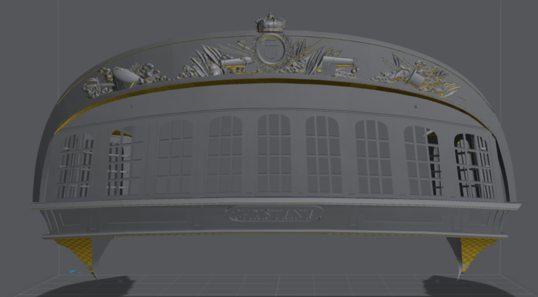
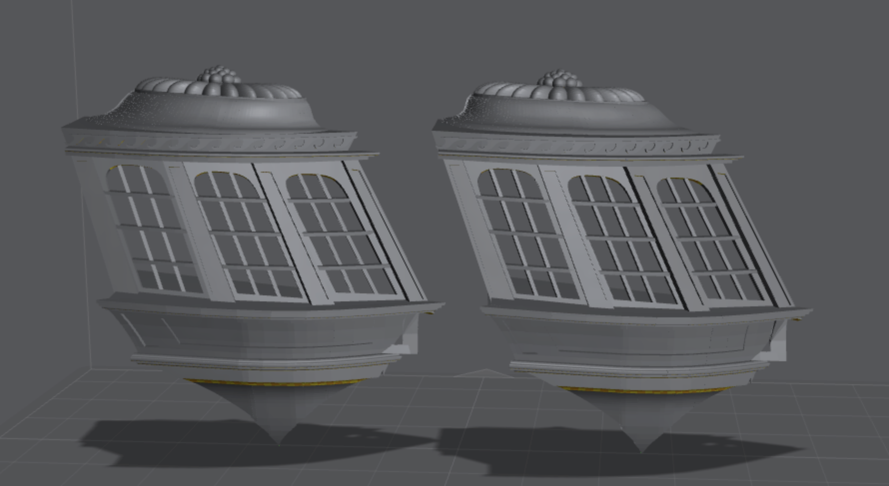
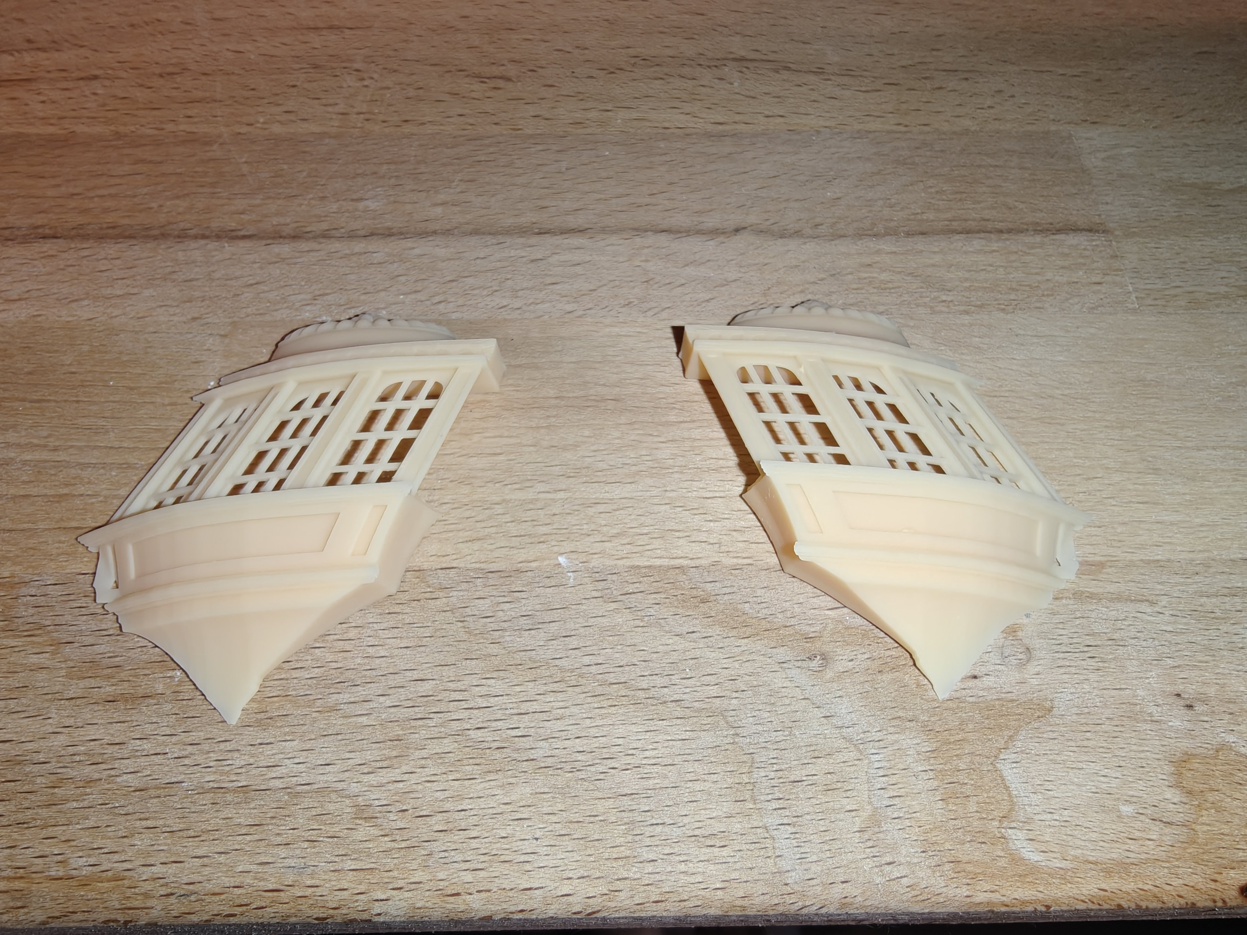
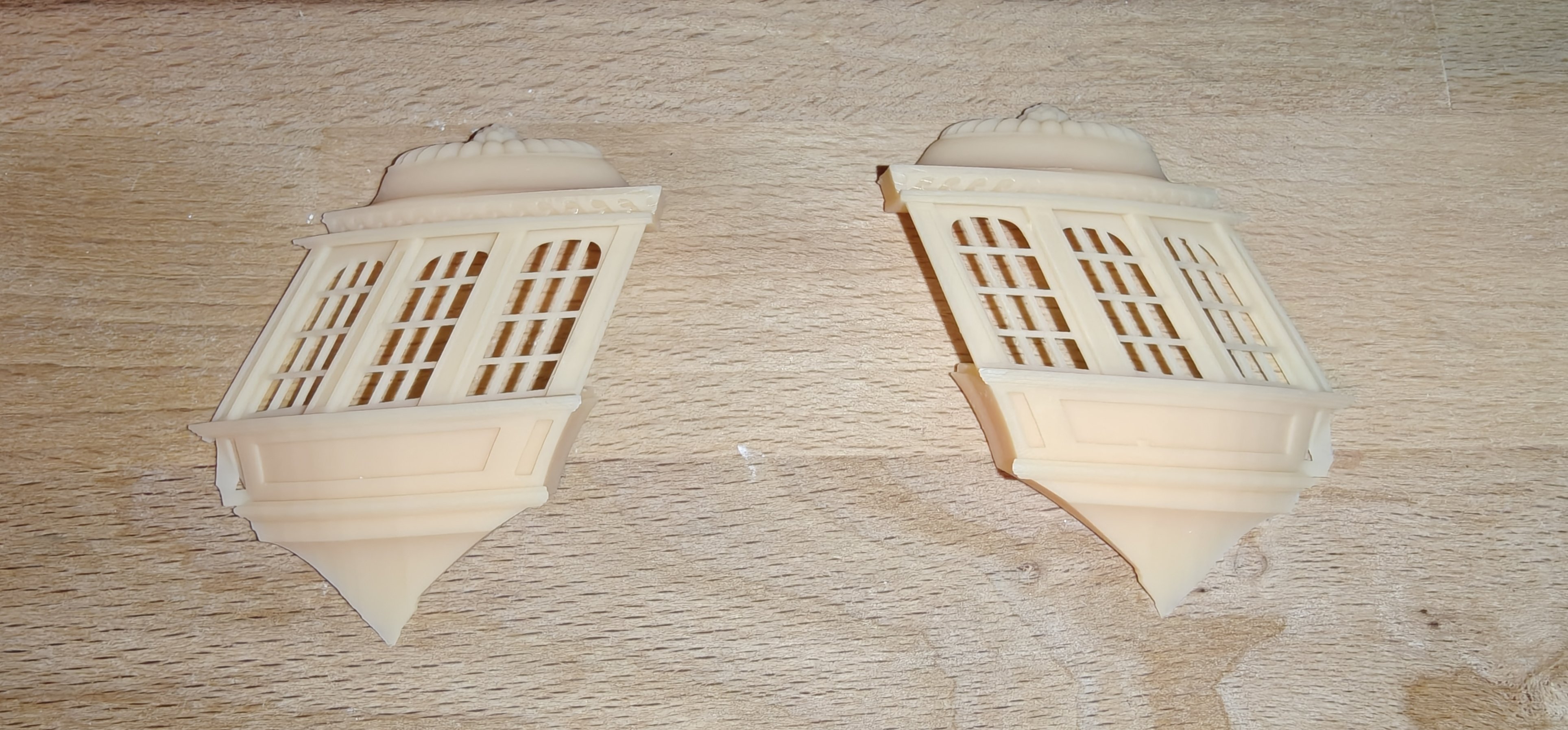
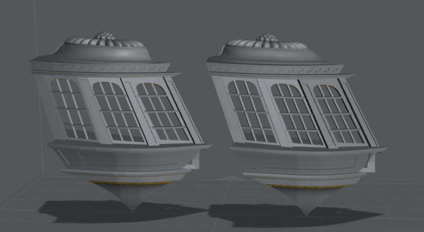
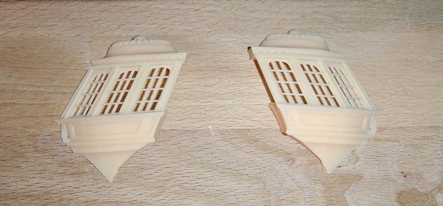
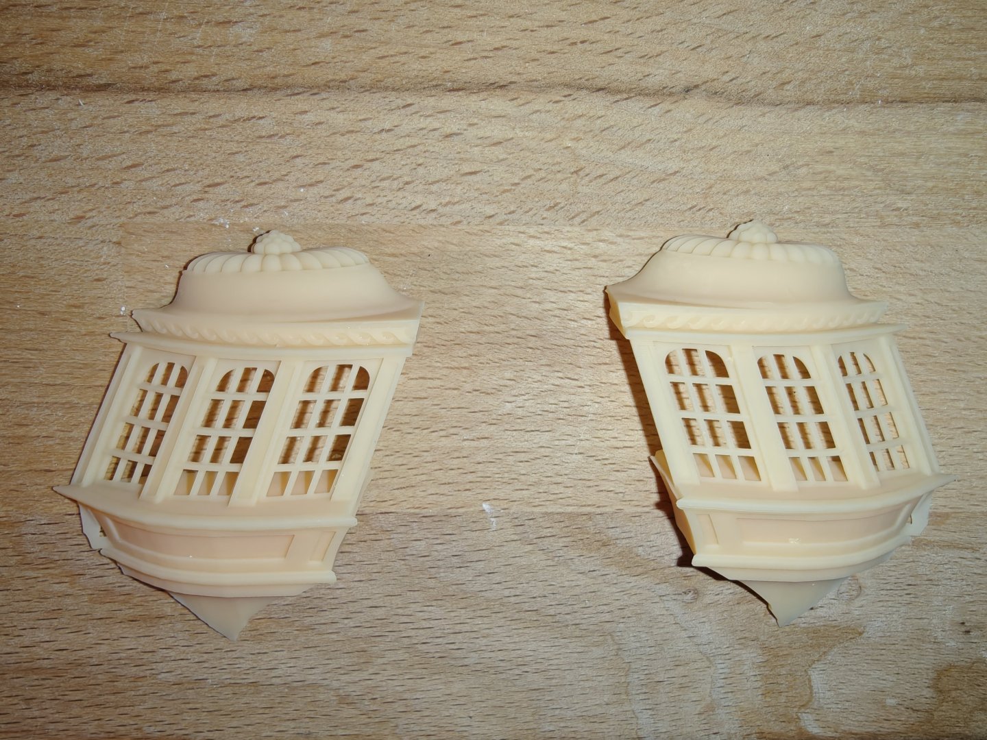
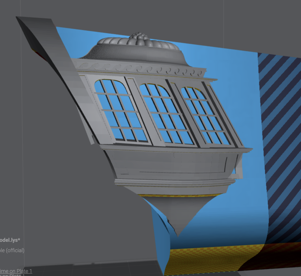
Alright, even though the 3D model has a few rough spots, I hoped that the tiny scale and the antialiasing used in the slicer on export would work in my favor. And I am very happy to report that it did! The finish looks really great and all the details pop. The prints cane out basically perfect. So I am very encouraged by this. Now, the fit for my Christiania is not quite good enough. I am not sure exactly what has happened, but the lower part and the top are both a bit too tall. The window portion seems to fit fine. So I will be scaling some parts of the model a bit and trying again to get a better fit. It wil likely not be perfect, so a bit of filler will be needed, but that is ok. Stay tuned for more experiments soon...

- 148 replies
-
- 9
-
-
-
- Christiania
- Vanguard Models
- (and 1 more)
-
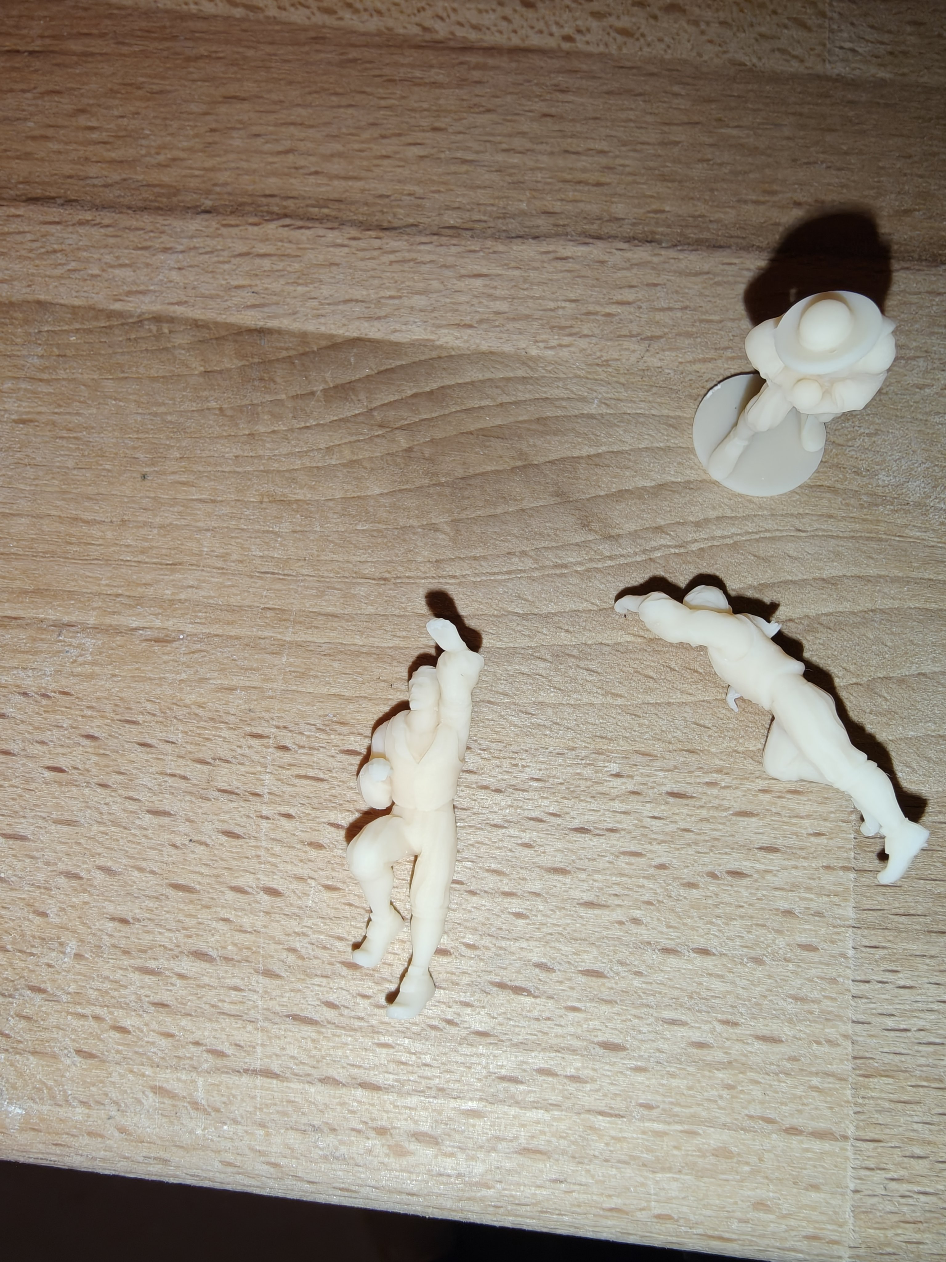
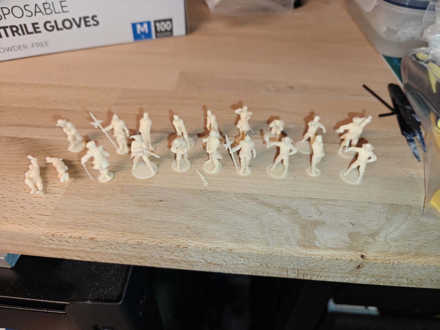
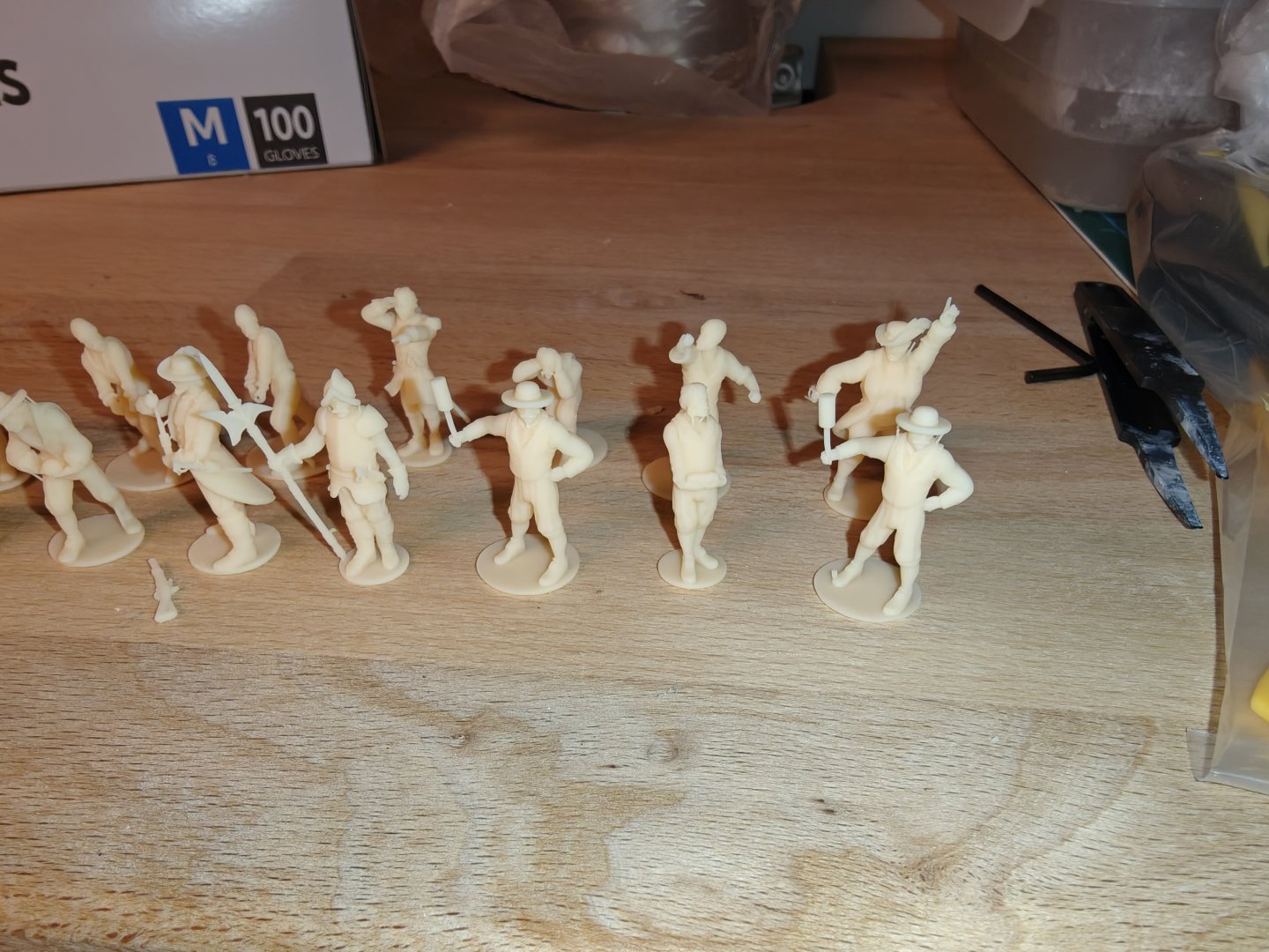
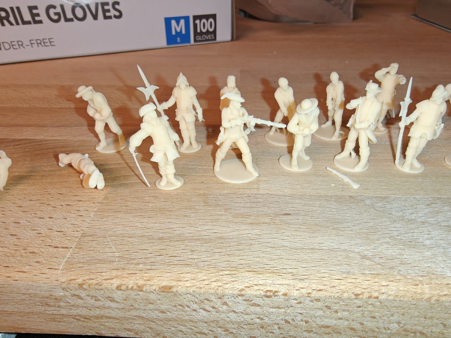
Here is a few of the latest additions - these are 17th century crew, officers and soldiers for future ship projects from that period. I have some very thin parts that would be completely un-viable for any commercial production. They all printed fine, but I broke a few during work-up. But I can just try a few times until I manage. These use very little resin at 1:64 scale.

-
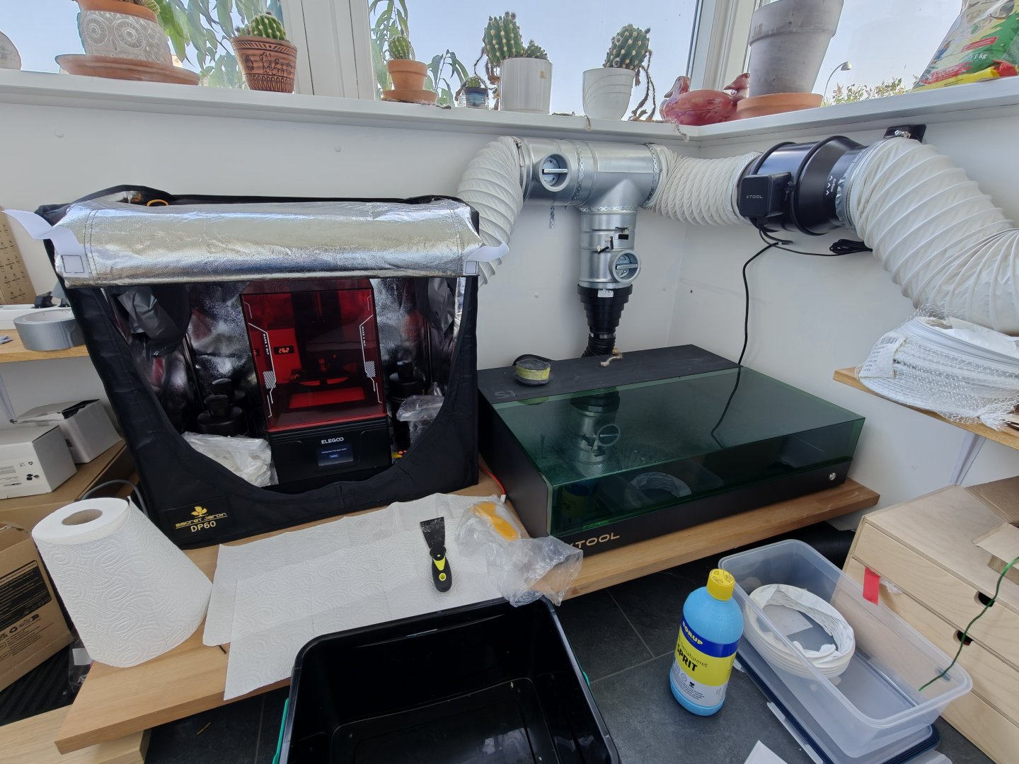
Hi Brunnels, I am by no means an expert at all, but here is my take: 1. Yes, but it is borderline with all the accessories needed, especially for washing, curing and installation. I think my printer was just around 200 USD, an Elegoo Mars 4 DLP. 2. Yes, it does. You will find opinions that it is totally harmless and those that say it is extremely toxic. The truth is probably somewhere in between. You need very good ventilation to the outside and a space that you can close off to the rest of the house when you have resin in the open. You should also avoid touching the resin - it is not super toxic, but it will cause allergic reactions. Either right away or over time. And I really dislike the smell which is quite strong when handling it in the open. I have the printer and the laser cutter hooked up to a small manifold with a big 200 mm fan. The printer is placed in a small growth tent - perfect for the purpose as I can ventilate it and keep stray light out. I keep the resin in the vat between runs and have a bathroom ventilator turned on when I am not printing to ensure no vapors seep into the adjacent living area. This is my setup: When I handle open or uncured resin I wear a half mask with organic vapor filters and I wear nitrile gloves - I use a lot of gloves and change them when I have touched uncured resin before I spread it around. I collect gloves and tissues in clear bags and uv cure them before disposal. I use water washable resin but still do a final rinse in IPA and collect water and IPA in clear plastic bottles that I can cure before I dispose of the content (or re-use the IPA). I am a chemist and this is what I have found to suitable for safe handling based on the safety data sheets and handling of similar chemicals in the lab. I wash twice with water and twice with IPA and reuse the wash medias many times before changing them. I do the wash in IKEA tupperware with silicone seals, very easy to use and keep. And I can cure them from time to time. It is a bit of hassle, but no step is difficult on its own and once you get the hang of it, it is not difficult and it does not take a lot of time. But I think you need a small dedicated space to make it hassle-free. 3. I am not sure what the machine can take, but the resin really needs to be at the right temperature, which is around 25C. Anything below 20C is supposed to work very poorly. I don't know about high temperatures but, I have printed with no issues up to around 30C. I guess this is very resin dependent! I have a heater inside the printing cabinet and have an electric radiator for the small room for winter use. I do think operating around living room temperature is preferable! This became a very long post, I hope it helps! I am happy to provide input and try to answer any questions you may have, but I also know there a much more experienced printers on this forum! BR TJM
-
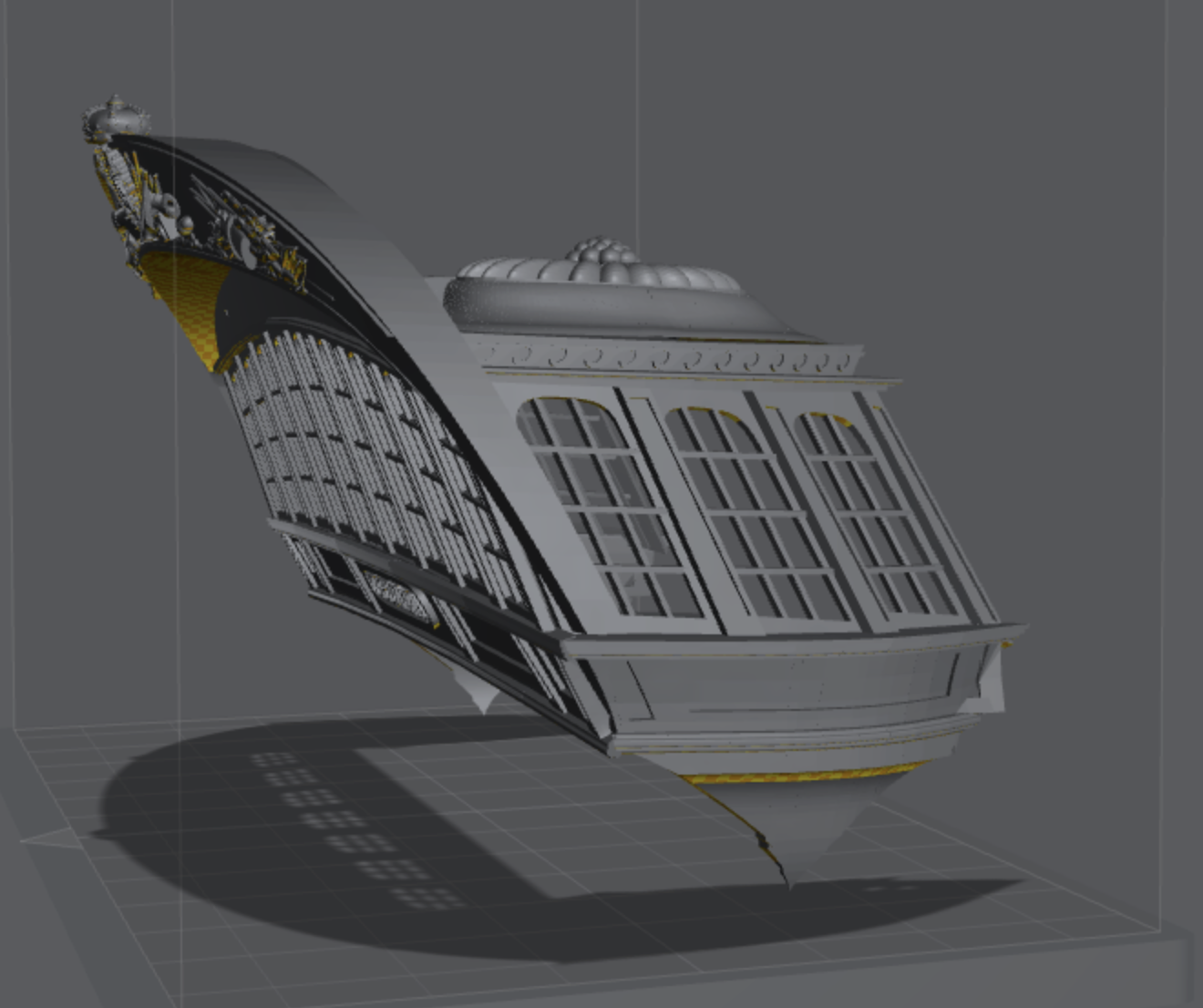
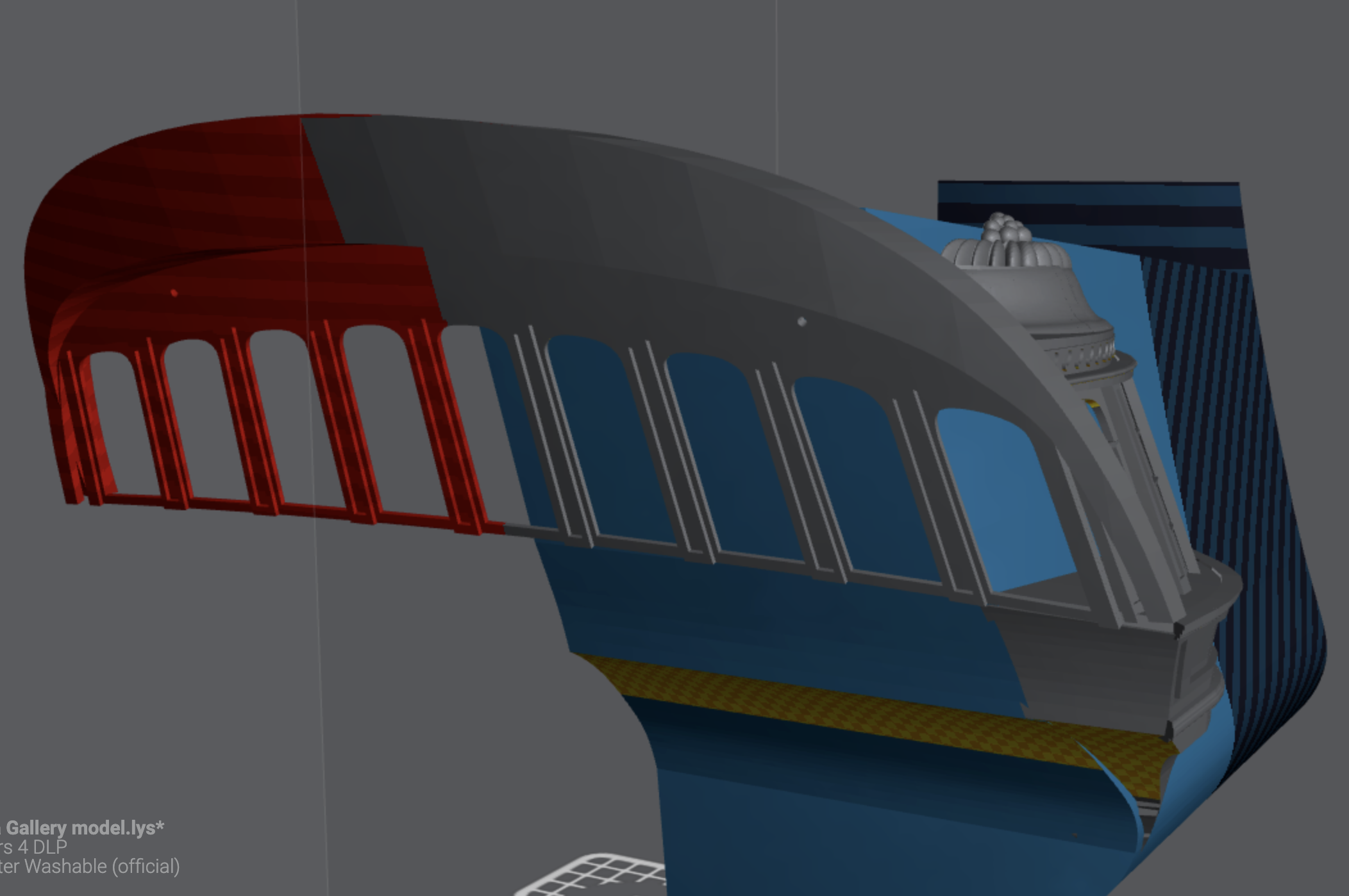
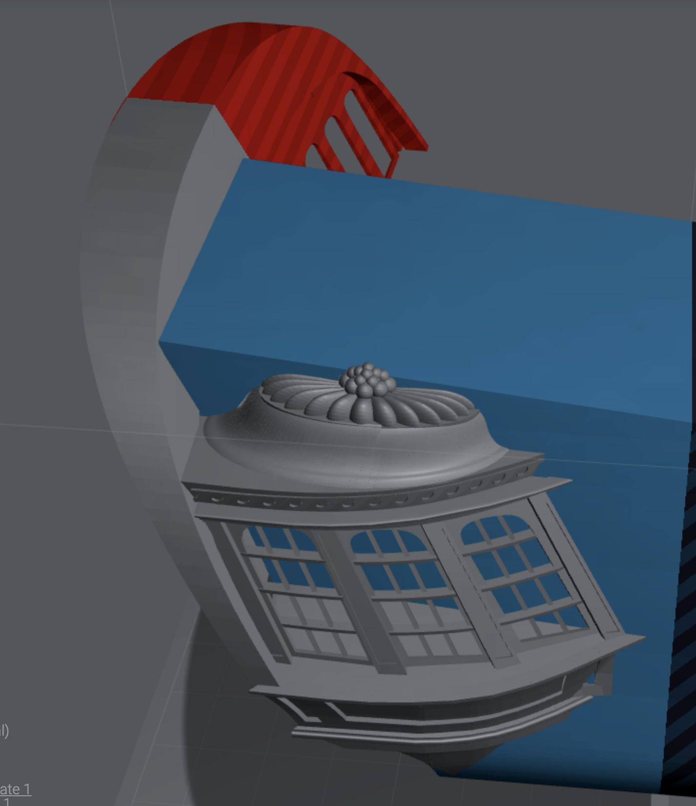
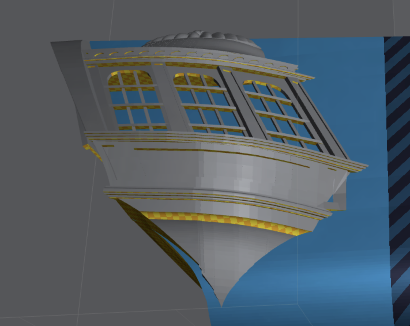
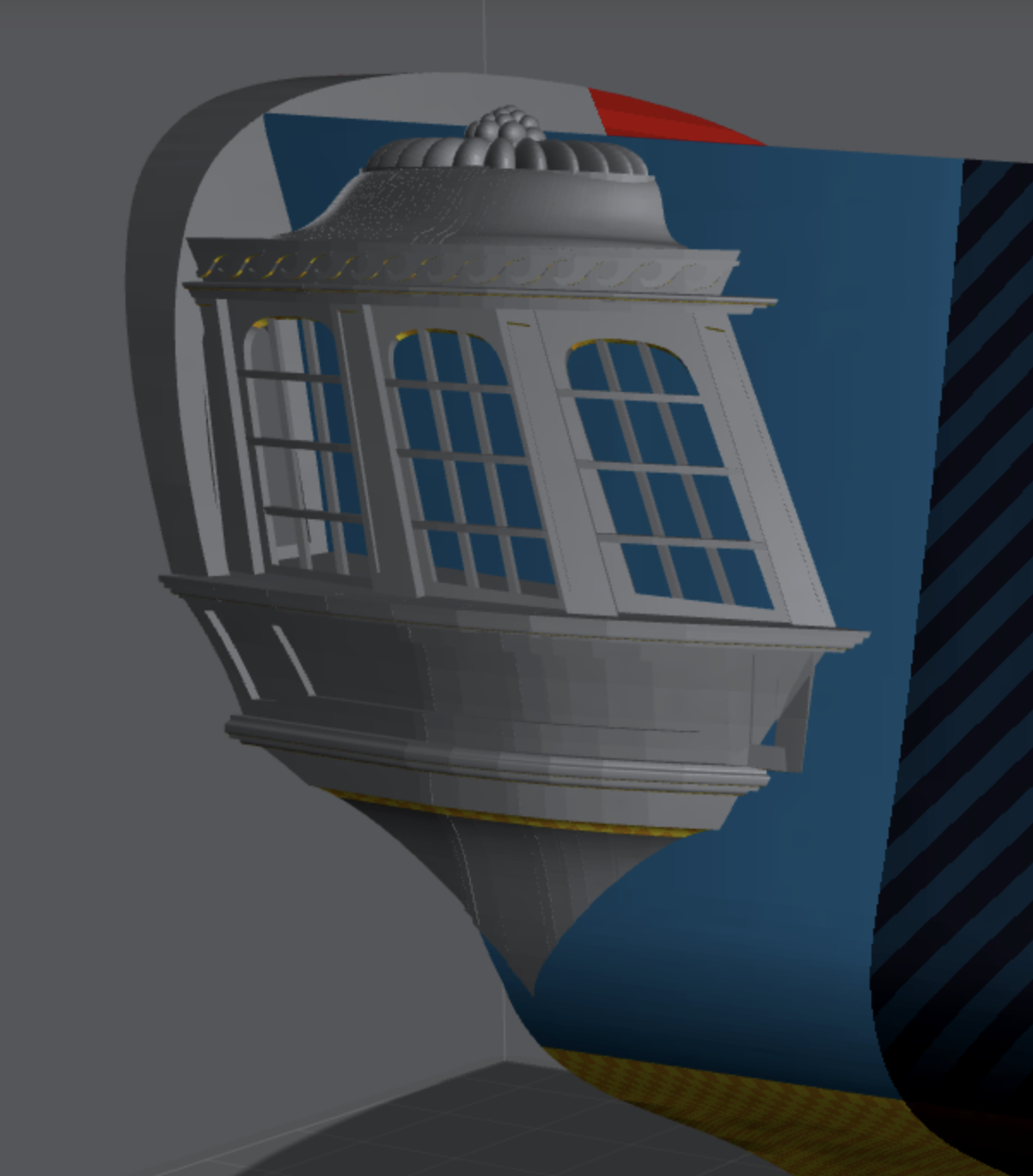
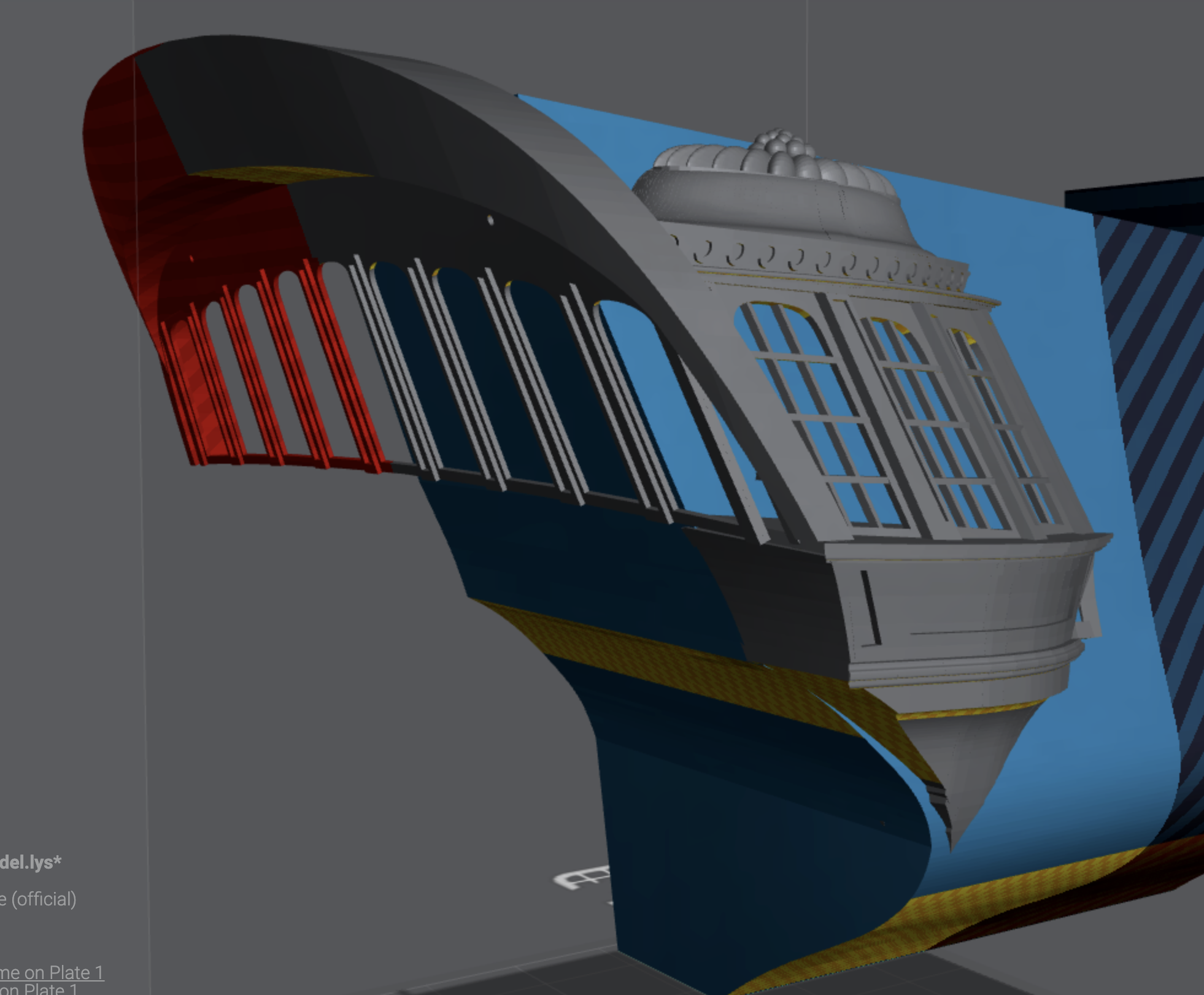
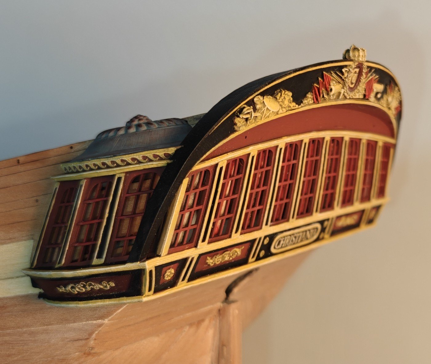
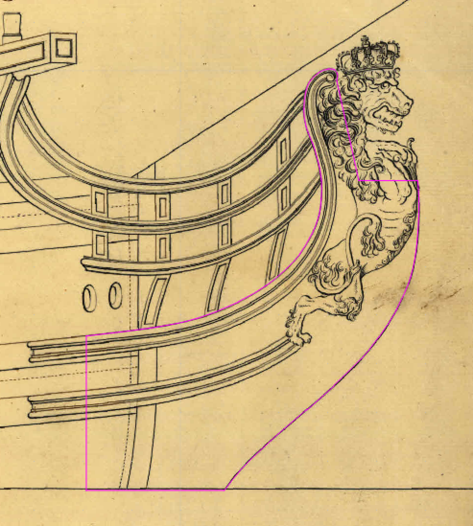
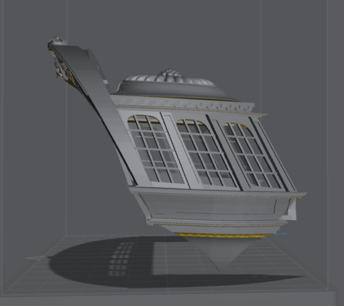
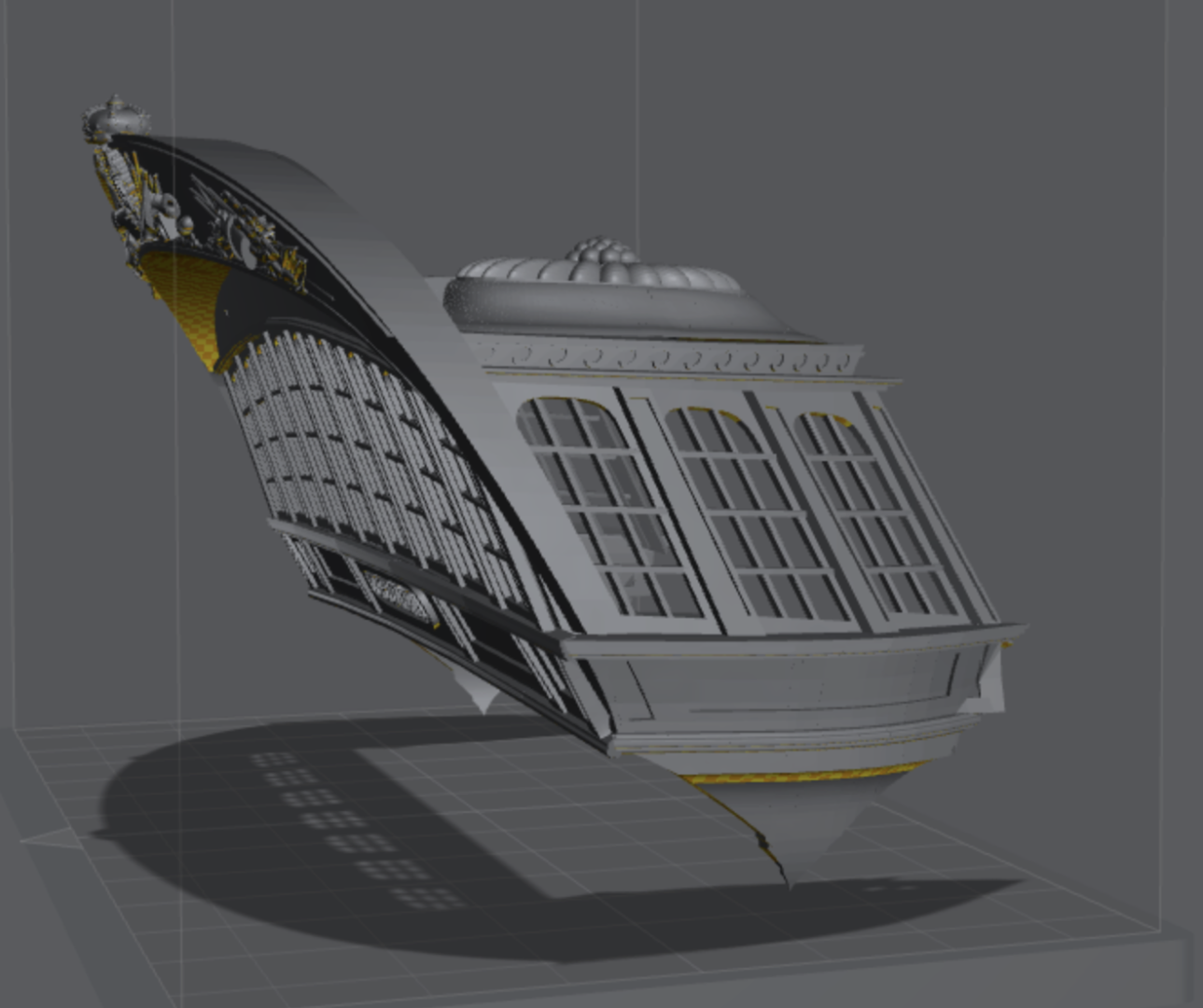
Log entry 26 - trying to model the side galleries Hi everyone, It has been quiet in this log for a good long while now - I have been on summer holydays, and after, I have been doing garden projects and working a bit on my Elben project. But even though planking is going painfully slow, I am working on other parts of this build as well. One of them is the stern decorations and side aglleries. I had originally though I would just make up modified parts for the side galleries, but the more I though about it, getting close to the drawings seemed to me a difficult task. I therefore decided to try to model the whole side gallerie in 3D, hoping I will be able to 3D print the whole thing. I have no prior skills in this area, and I am not ready to start learning to actually model in a 3D CAD program, so I have been using some workarounds: I am drawing simple parts based on the original scalled drawings in QCAD. Then I load these into Onscape and extrude them to a resonably close thickness (I can modify this later, so it does not need to be procise). Then I import into the slicing software I use for the 3D printer and build everything in there. This is surely a bad way of doung it, but the interface in the slicer is super simple and at the same time offers full flexibility when it comes to positioning and scaling parts - I just can't make any more advanced modifications to the individual parts, except for straight cuts! I am not done yet, but this is the current state of things: Here are the original drawing I am trying to approximate: I am happy with the overall shape, except for the very lowest portion of the side gallery - it is a very dificult geometry, and I just can't get it wide at the bottom. I may end up just deviating a bit from the drawings in this area. I have tried many multiple times and it just ends up looking bad. I would rather have a deviation from the original that looks good, than something cunky and ugly! I am still in the process of adding ornaments and I just started the modelling of the stern face. I am not sure I will 3D print the rear windows, but I would be nice to have the window frames match the side galleries, so maybe I will give it a shot. The friese is blank here - as you can see in the posts above, I have modelled the friese, but in a flat version. I figured a way to get the correct, thick 3D shape and I think I will import my other friese file and transfer the design to the curved surface. I will then re-print it to get a much better final shape of that piece. No matter what, I will print the stern friese and/or windows seperately from the two side galleries. I think I will do an export and make a test print before moving much further, just to see if this is a viable approach at all - it is a time sink to do this, so I want to make sure it is worth it! BR TJM


- 148 replies
-
- 10
-
-
- Christiania
- Vanguard Models
- (and 1 more)
-
Beautiful! And that hull...!! 🤩
-
@chris watton, are you using lase etched pear parts for the decorative columns and border? They look great!
-
I am sure this will be a magnificent kit, can't wait to see the build here! Just the part shots above is enough to show that this will be great!
-
It does sound reasonable, but the little circumstantial evidence I have seen suggests that it may have been coppered. The model of the smaller sister ship Delphinen at the War Museum in Copenhagen is shown as coppered, and it was a guard ship at Nyborg, which is entirely within the 'home water' boundary. I don't know if the model builder Peter Maack had any hard evidence of the coppering of Delphinen, but I will go with it on this model as well.