
TJM
-
Posts
362 -
Joined
-
Last visited
Content Type
Profiles
Forums
Gallery
Events
Everything posted by TJM
-
This is looking really nice!
-
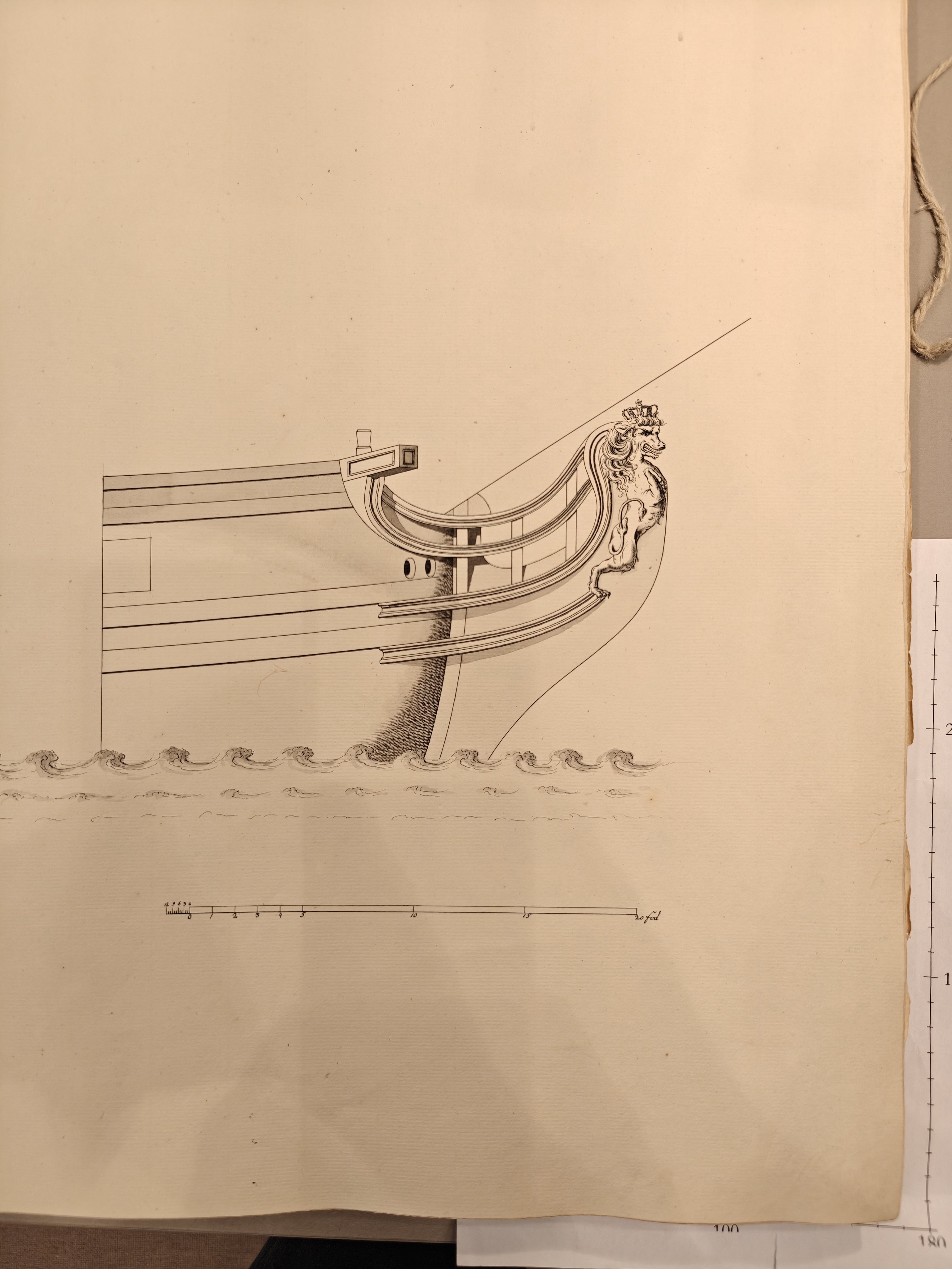
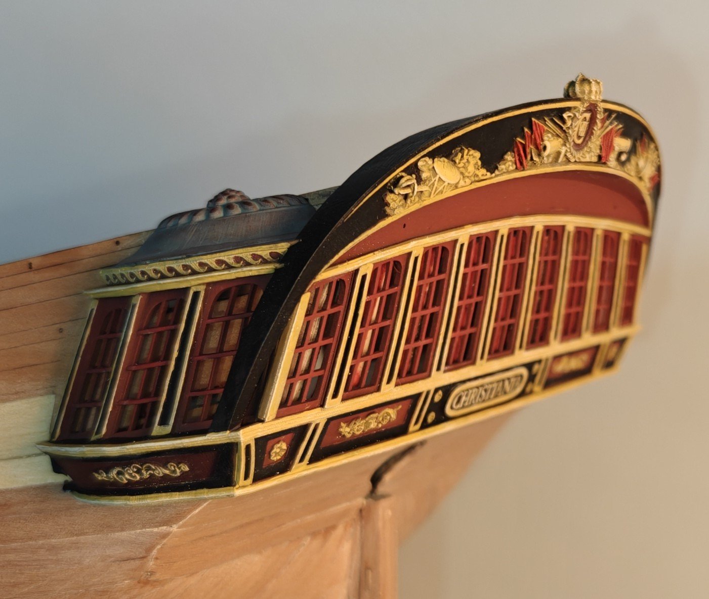
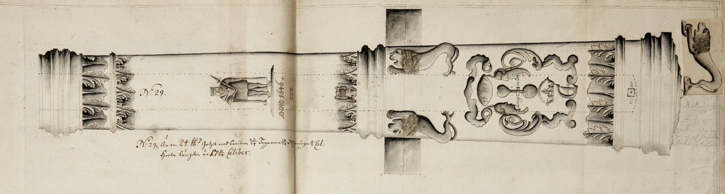
Very nice Arthur! Hvide Ørn is a very pretty ship indeed! Here's a slightly more detailed image of the figurehead that I took at the Danish National Archives: This particular copy of the original had not been scannet yet. It is designated H18.
- 49 replies
-
- 2
-

-

-
- Wildmanden
- Turesen
- (and 1 more)
-
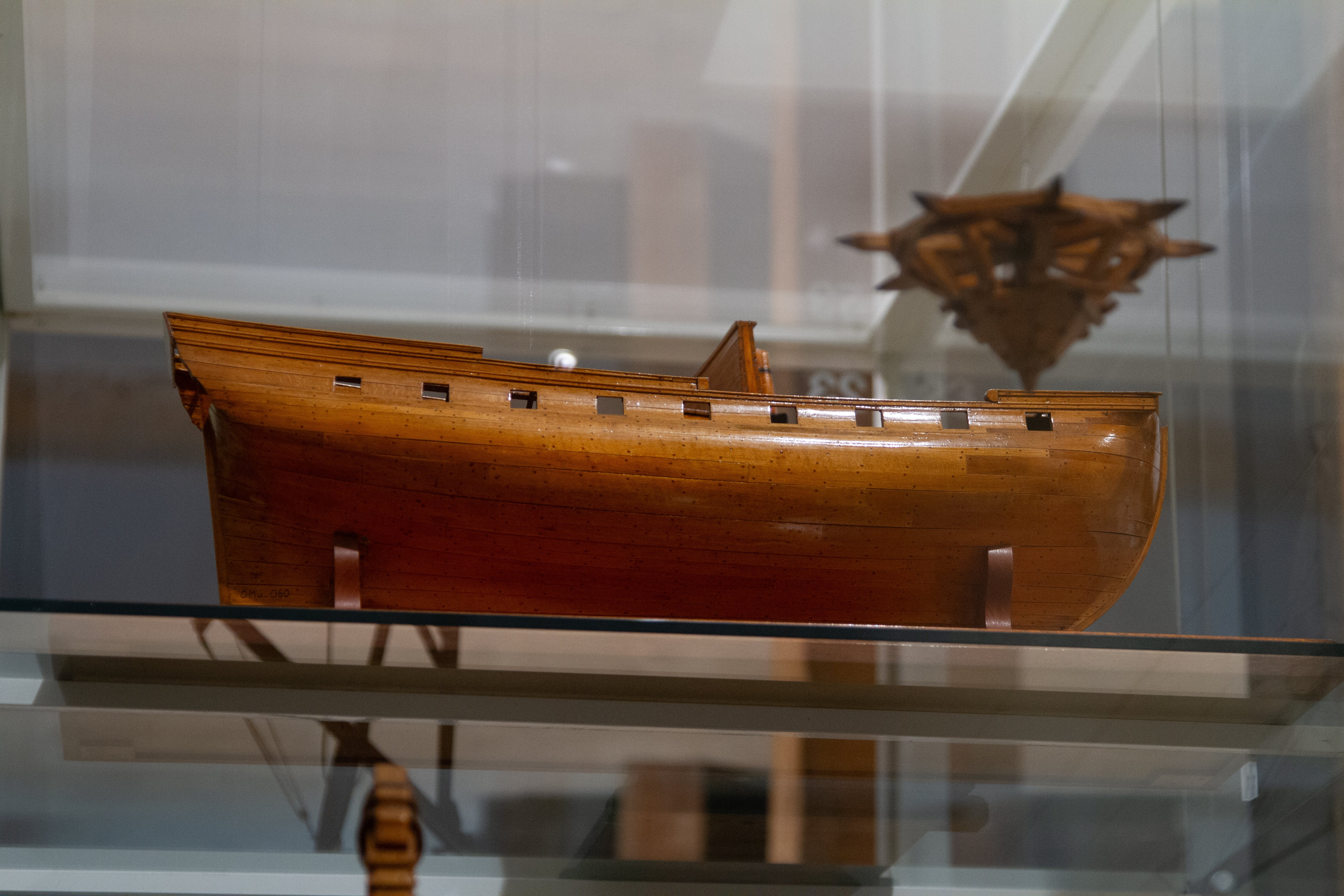
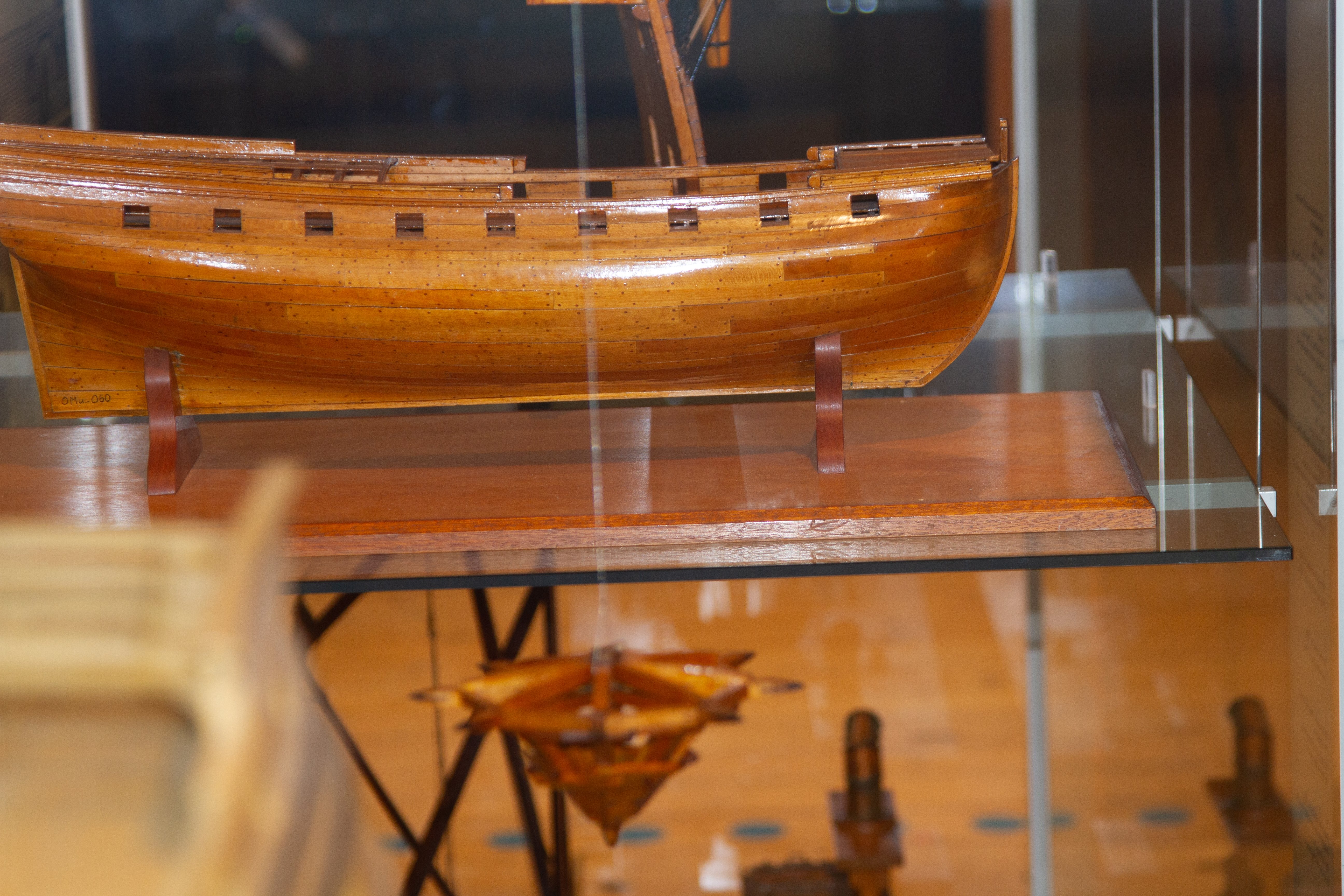
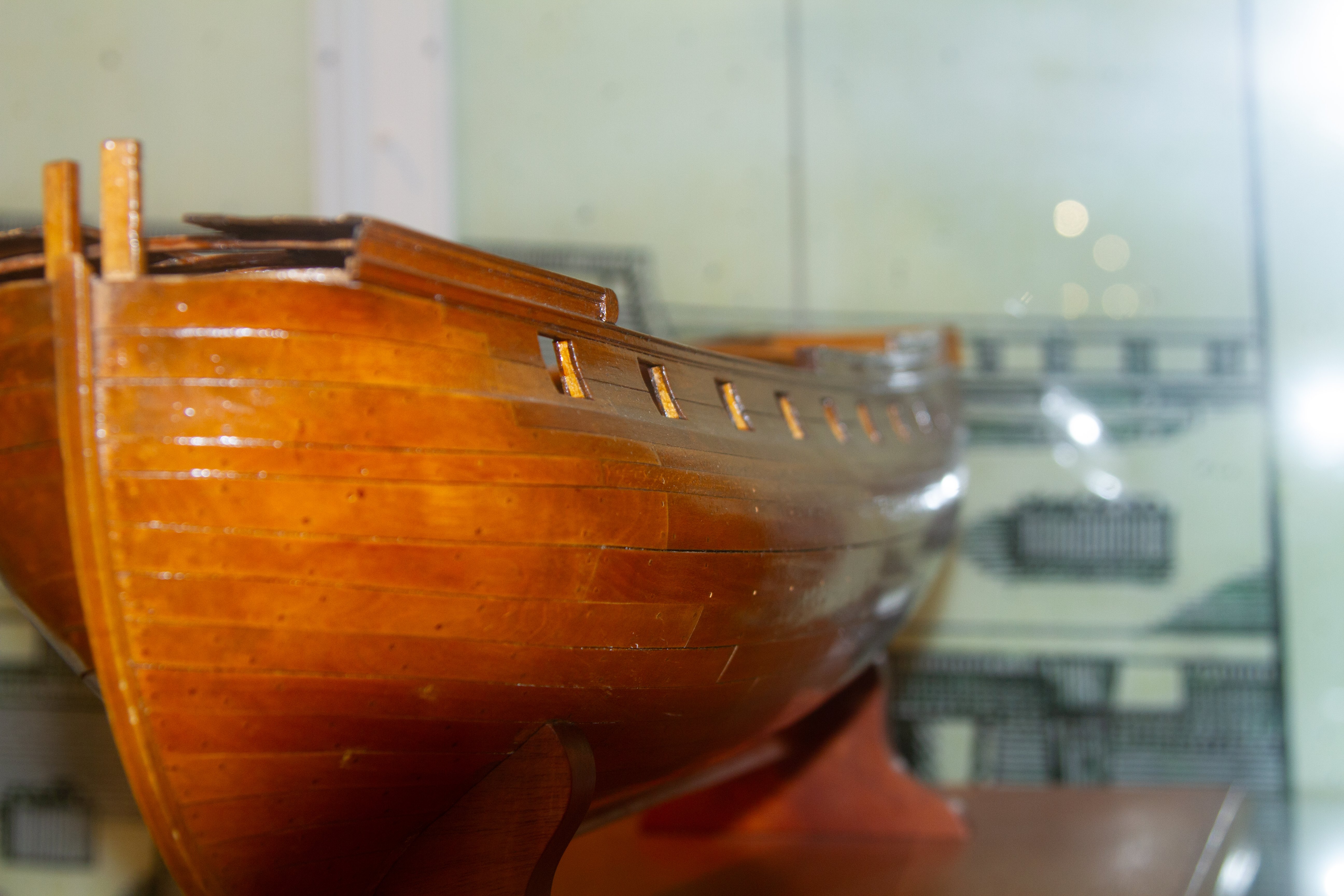
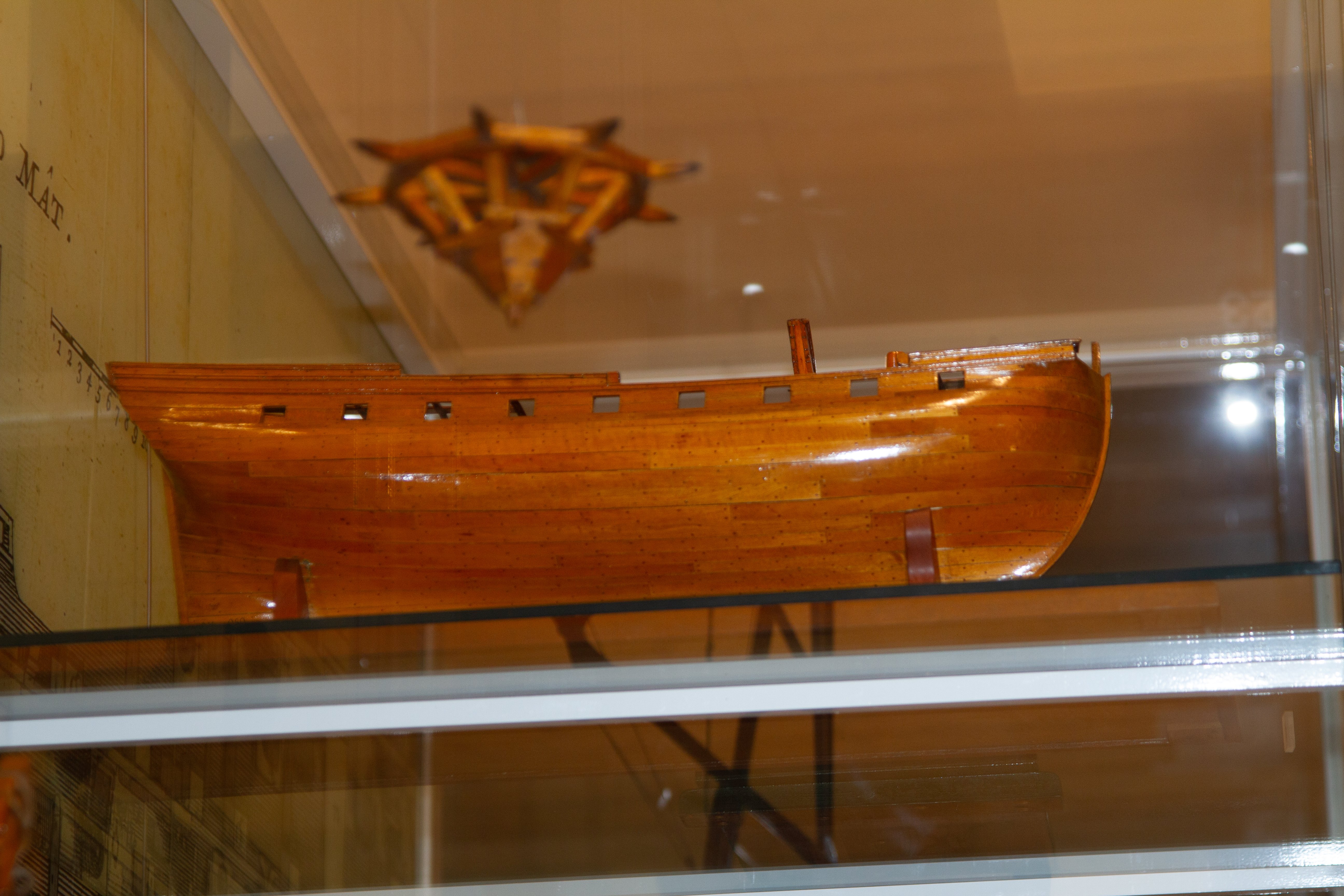
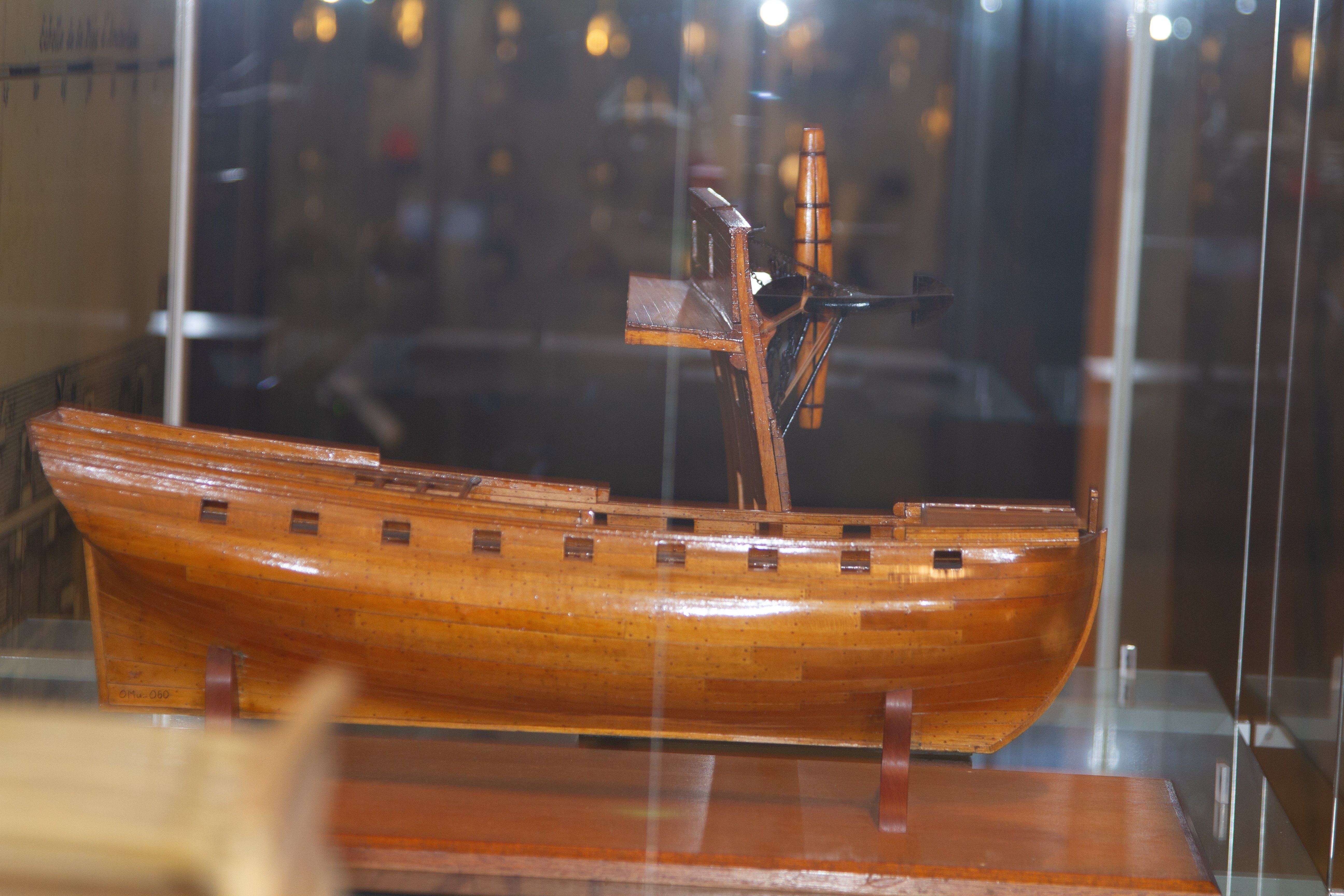
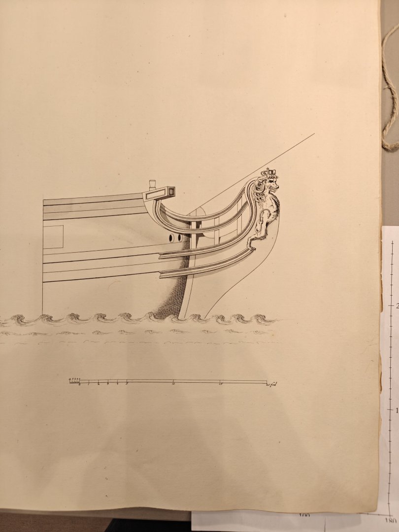
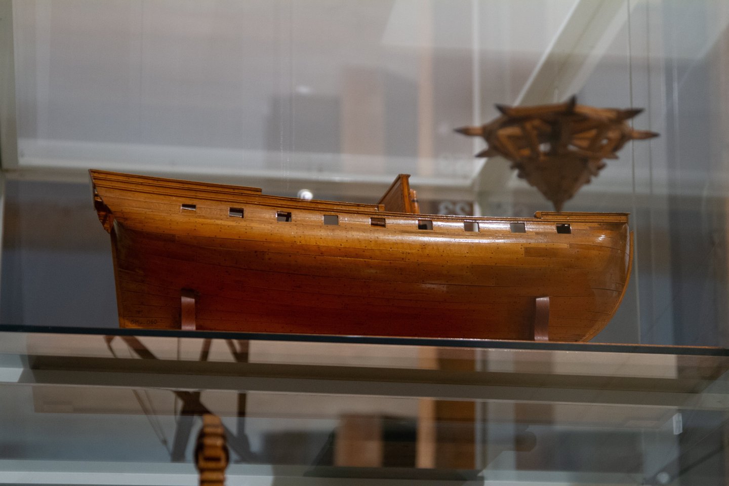
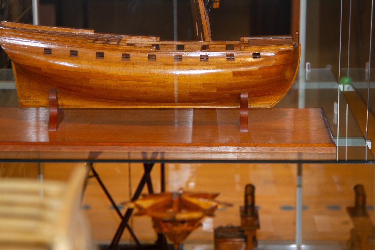
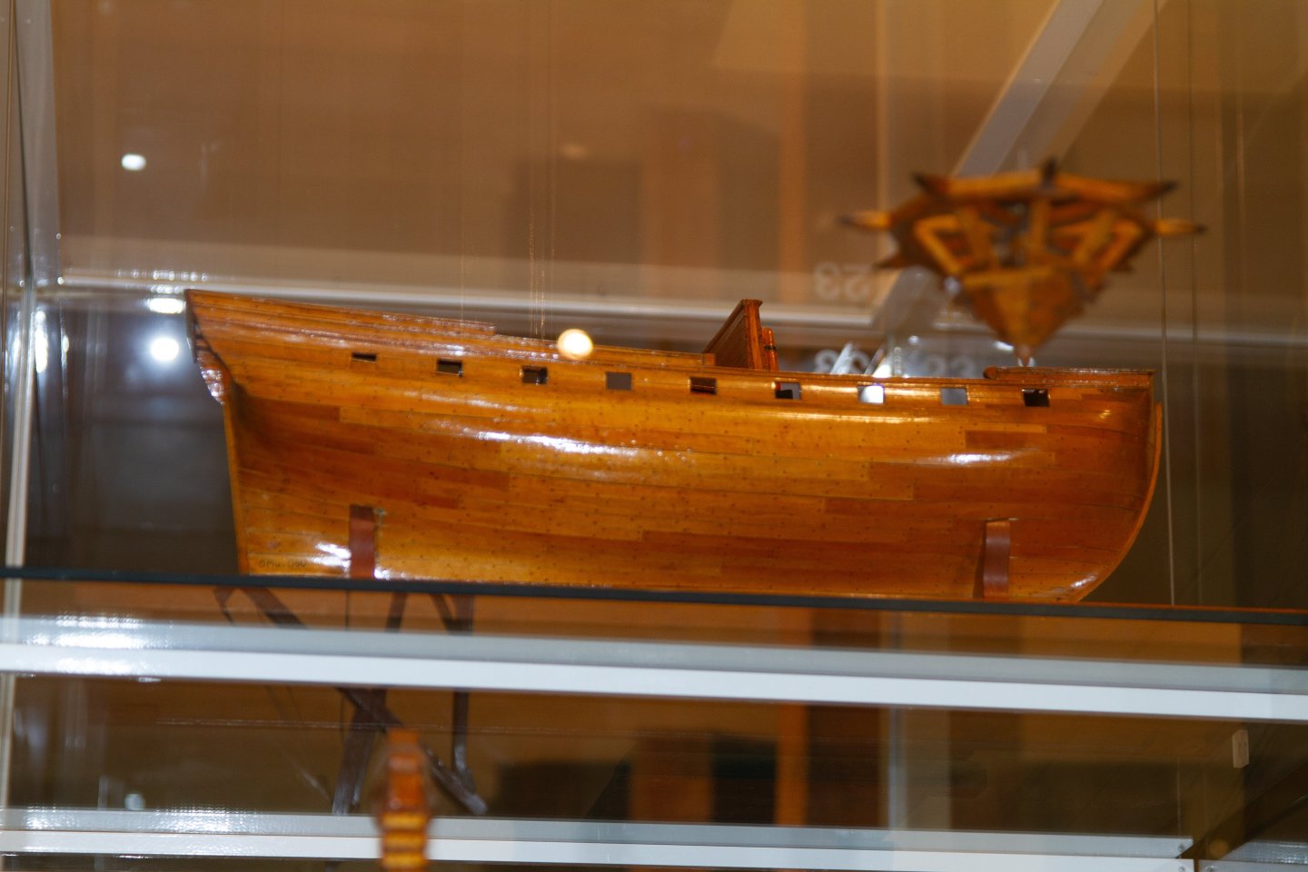
Hi Arthur, I am quite impressed - I have yet to sit down and actually understand how these constructions were made from mathematical principles, but would love to get into that some day. I passed by the Krigsmuseeum the other day and tried to grab a few shots of Wildmanden - It is very dificult to photograph it, as the model is small, the prow is facing the frnt of the display case, and the case is very large, so it is hard to get a proper profile shot. I am not sure these will really help you, but perhaps there is somthing to be seen on them still 🙂


- 49 replies
-
- 5
-
-
-
- Wildmanden
- Turesen
- (and 1 more)
-
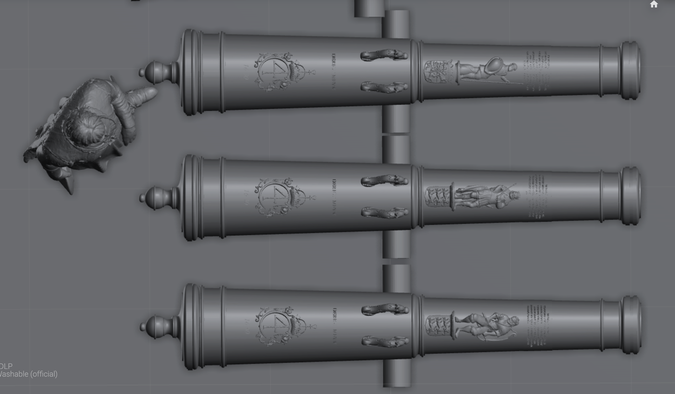
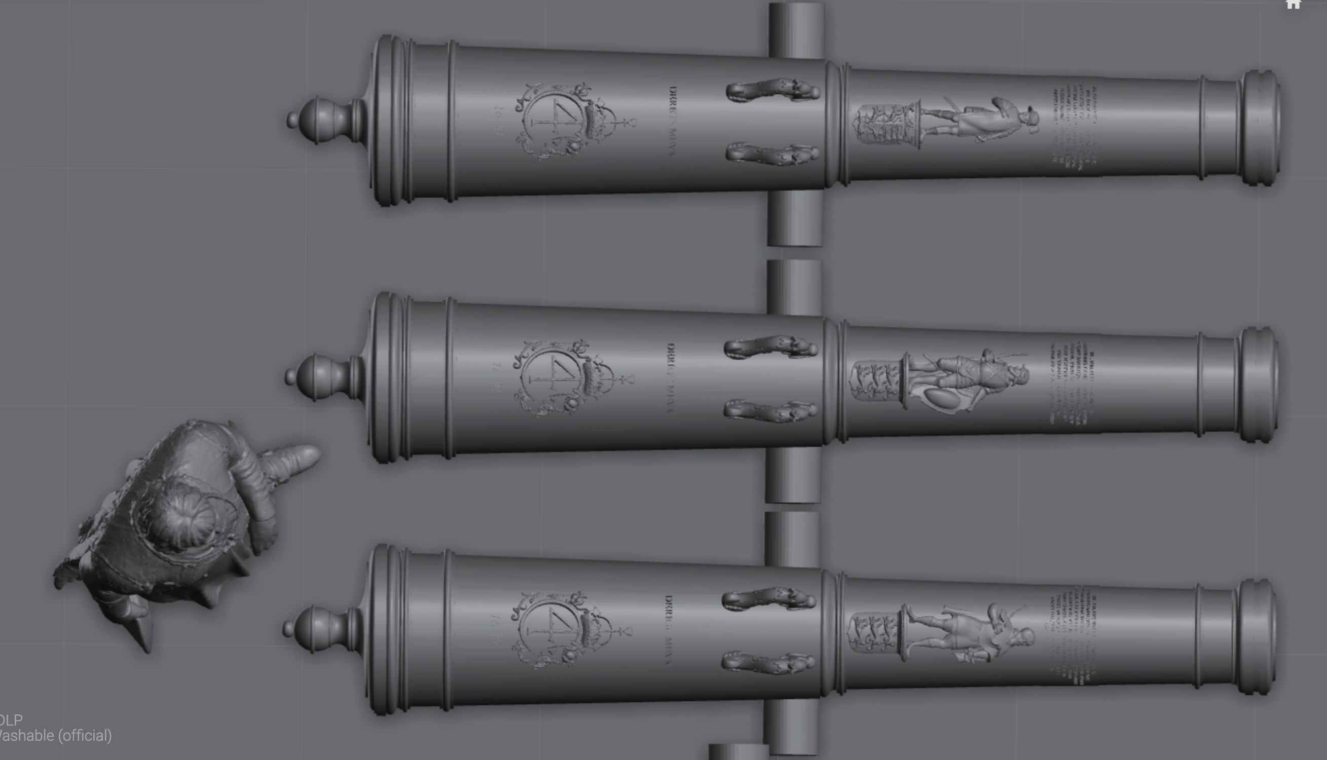
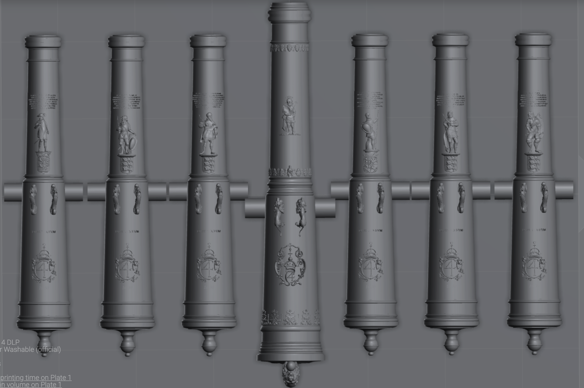
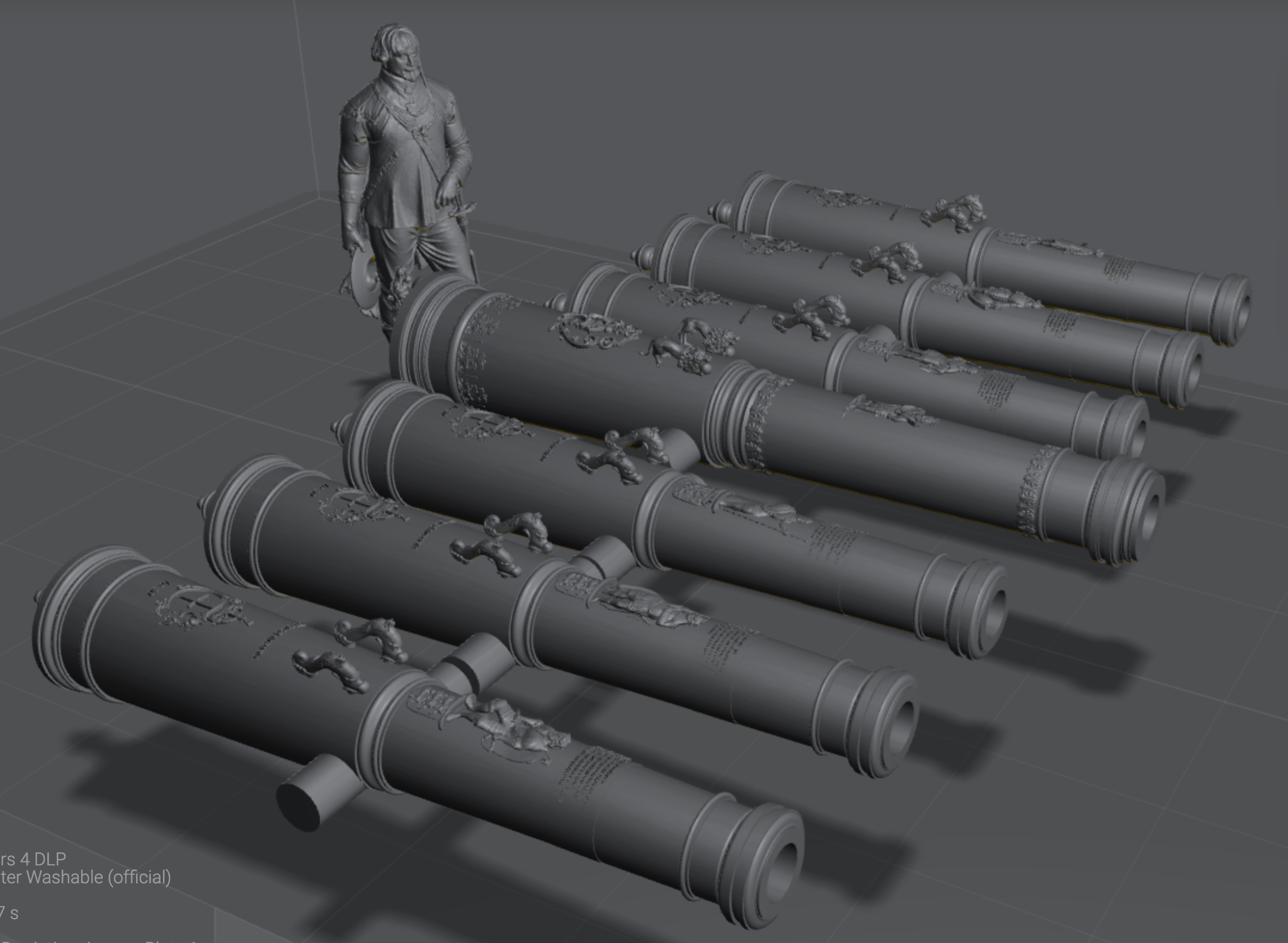
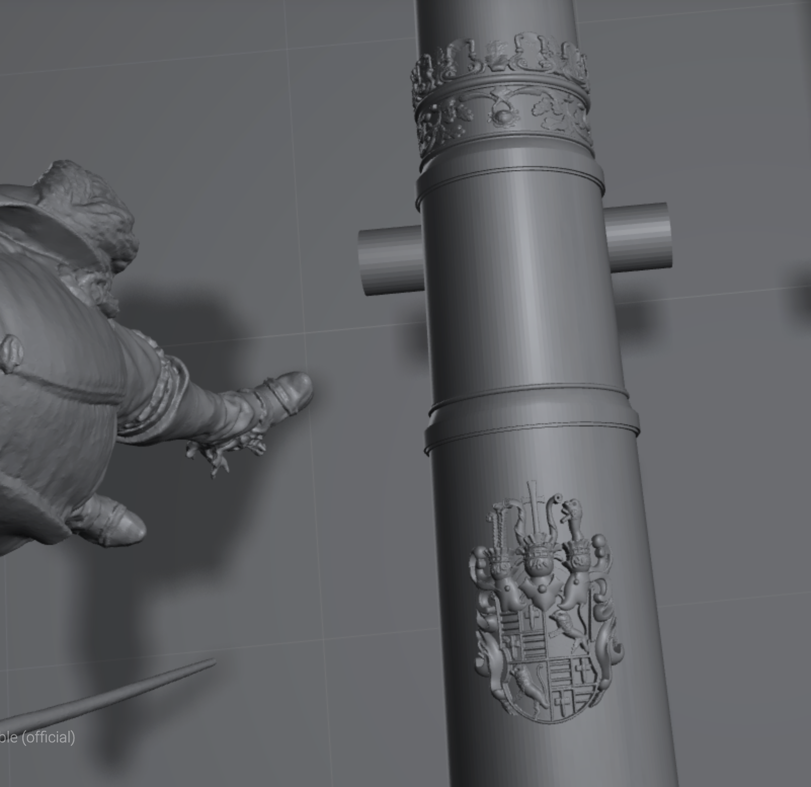
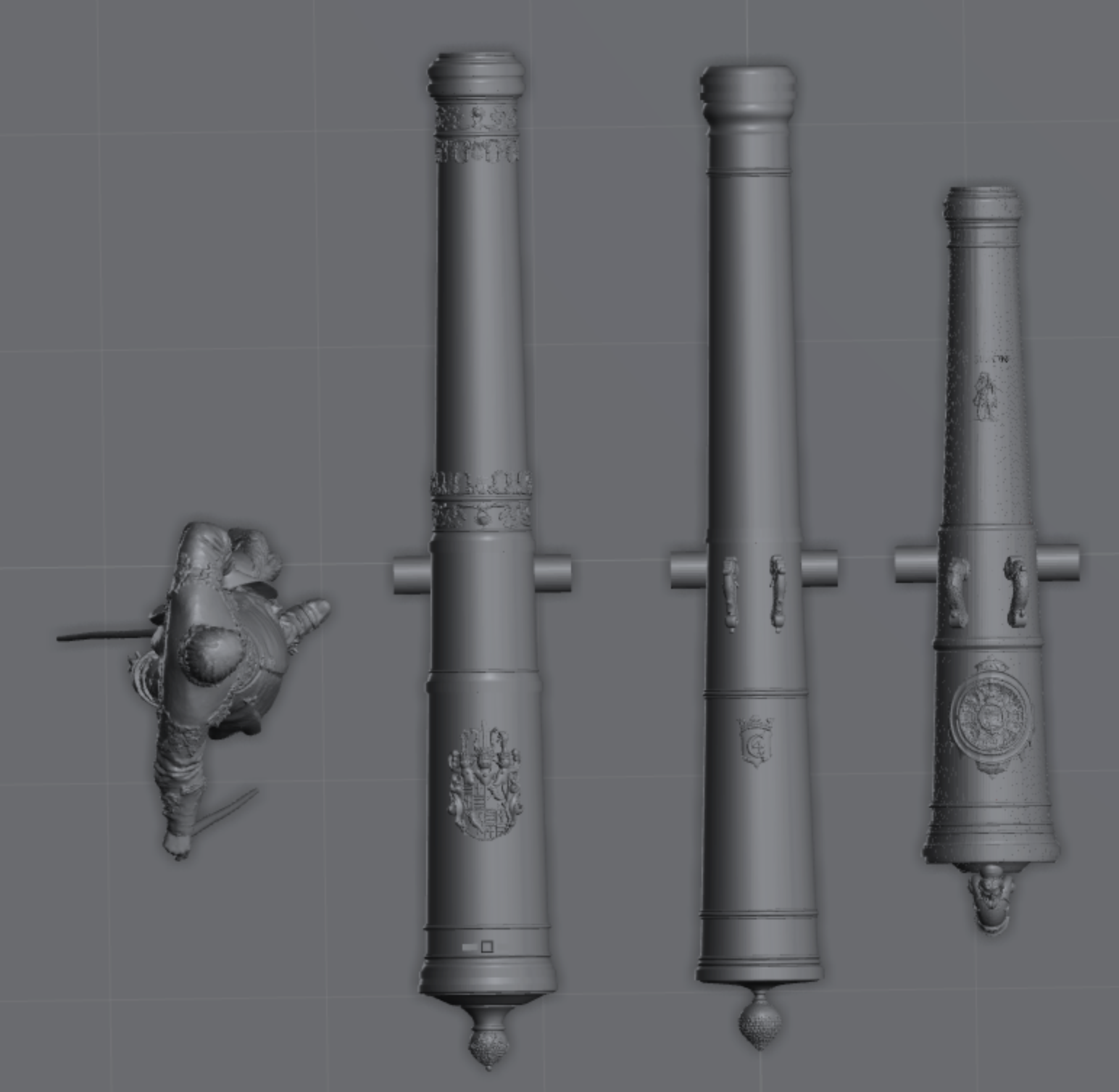
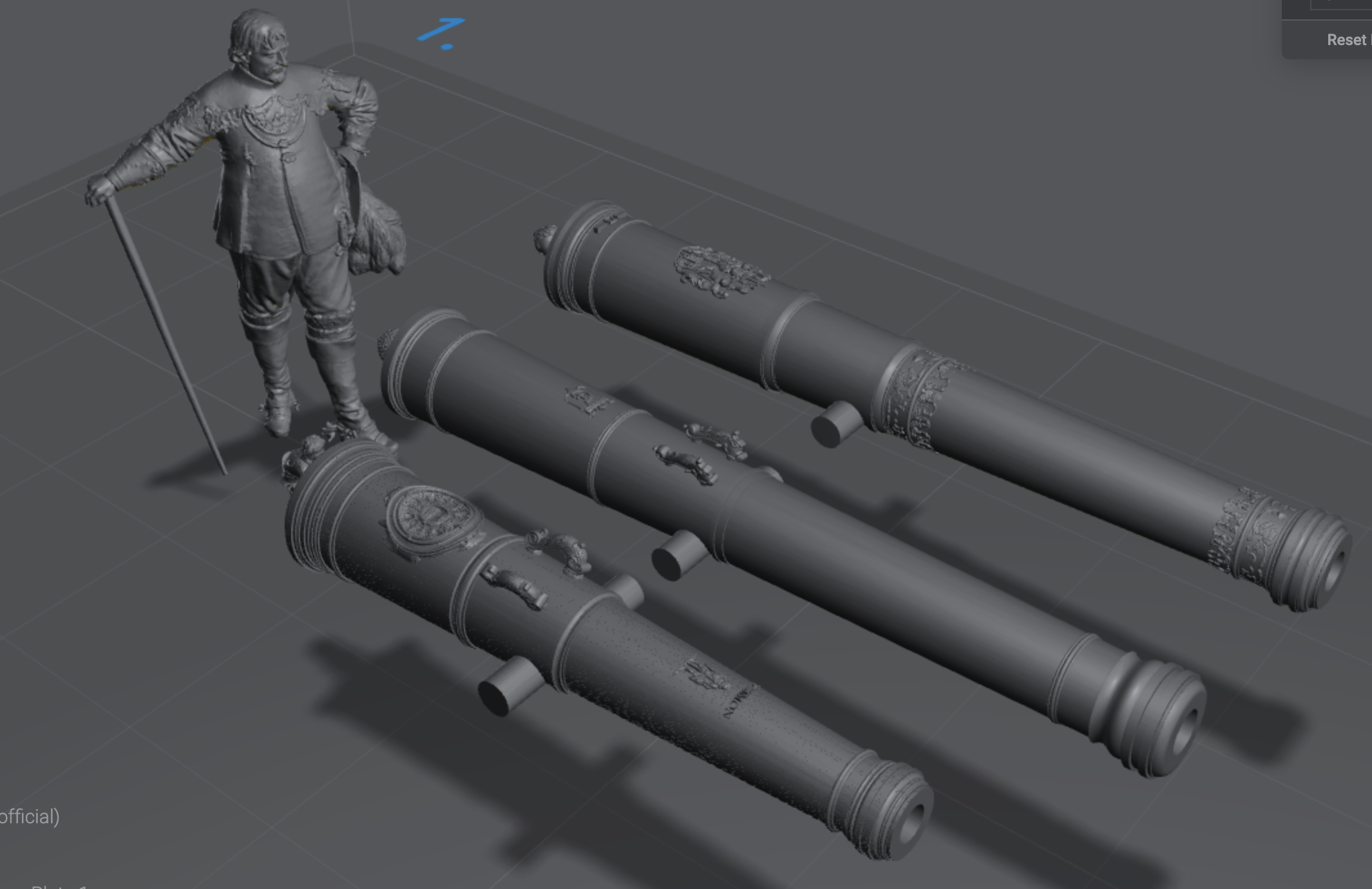
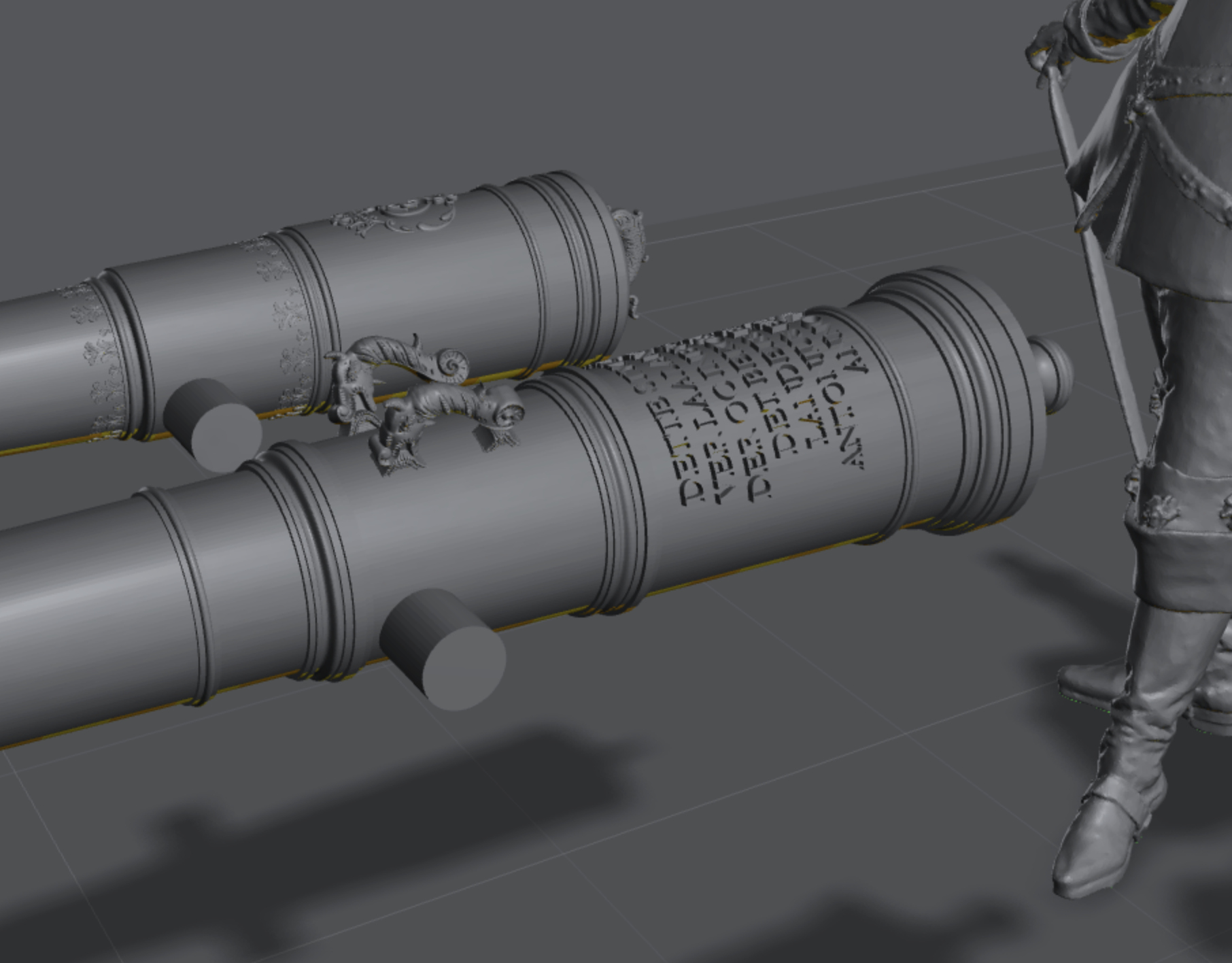
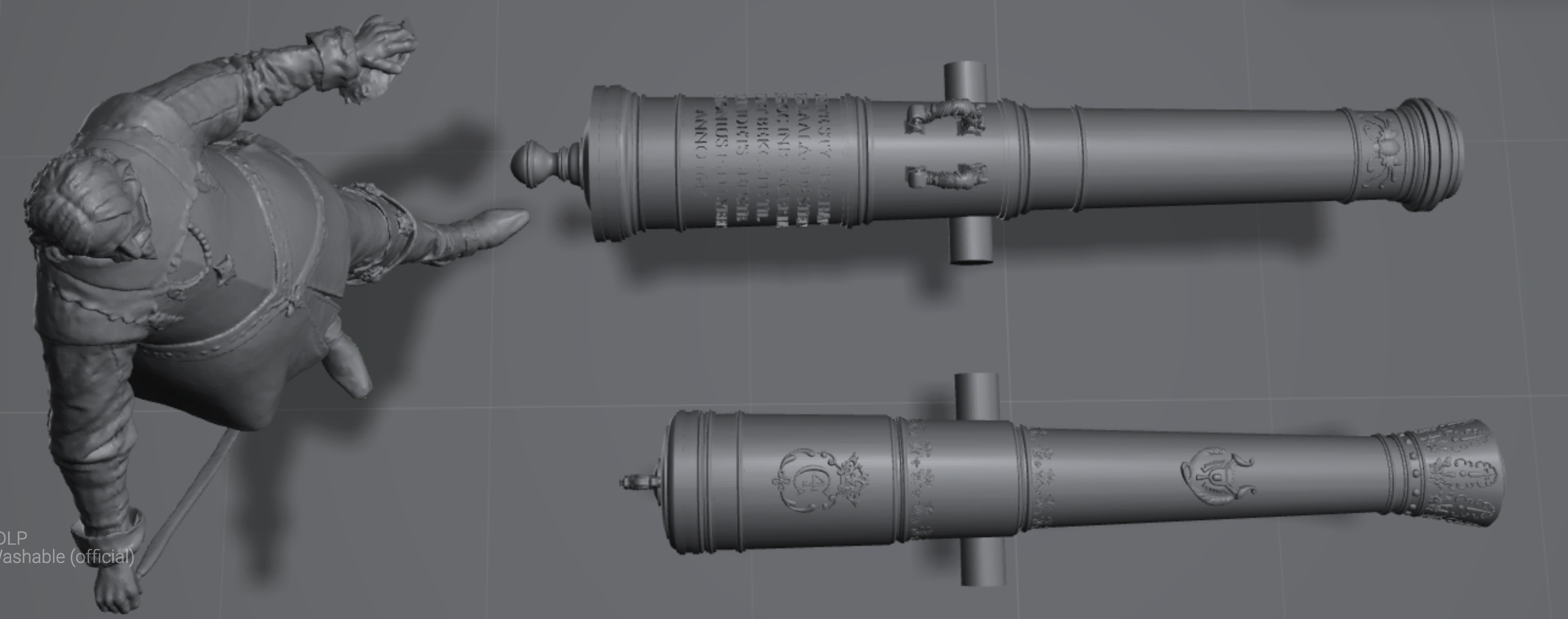
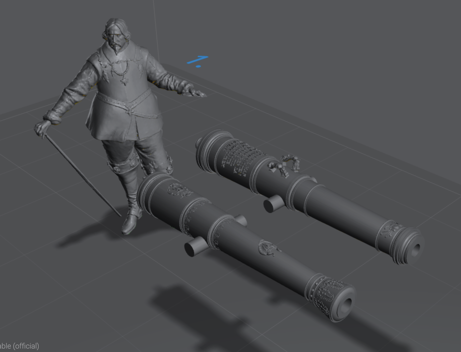
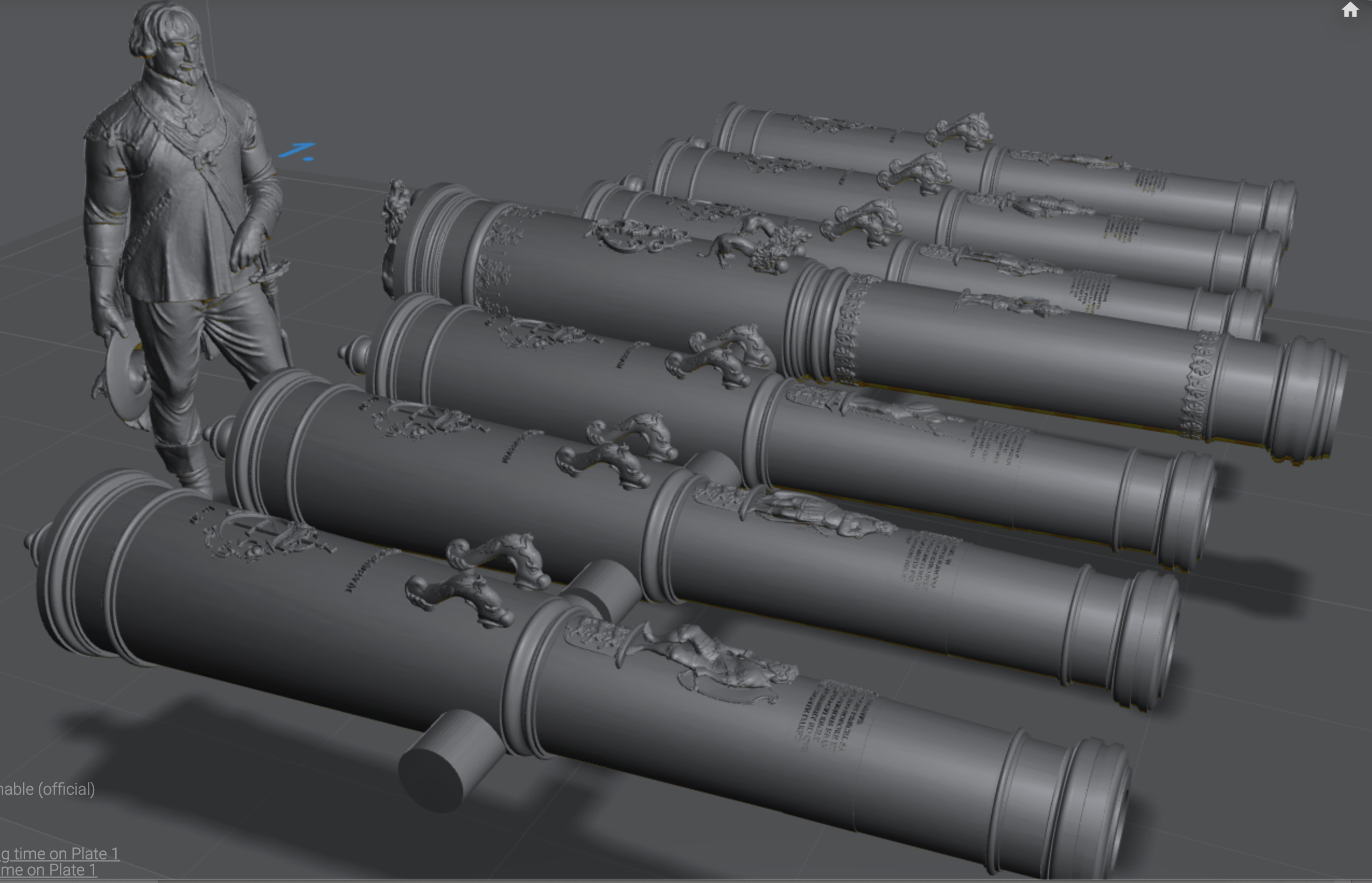
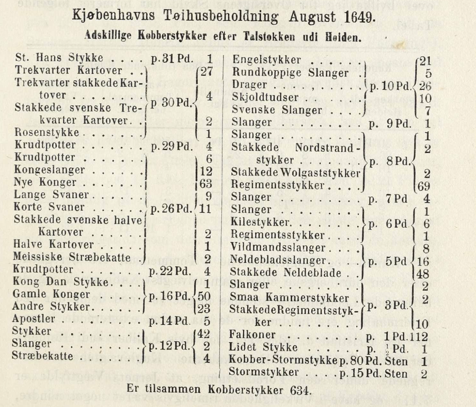
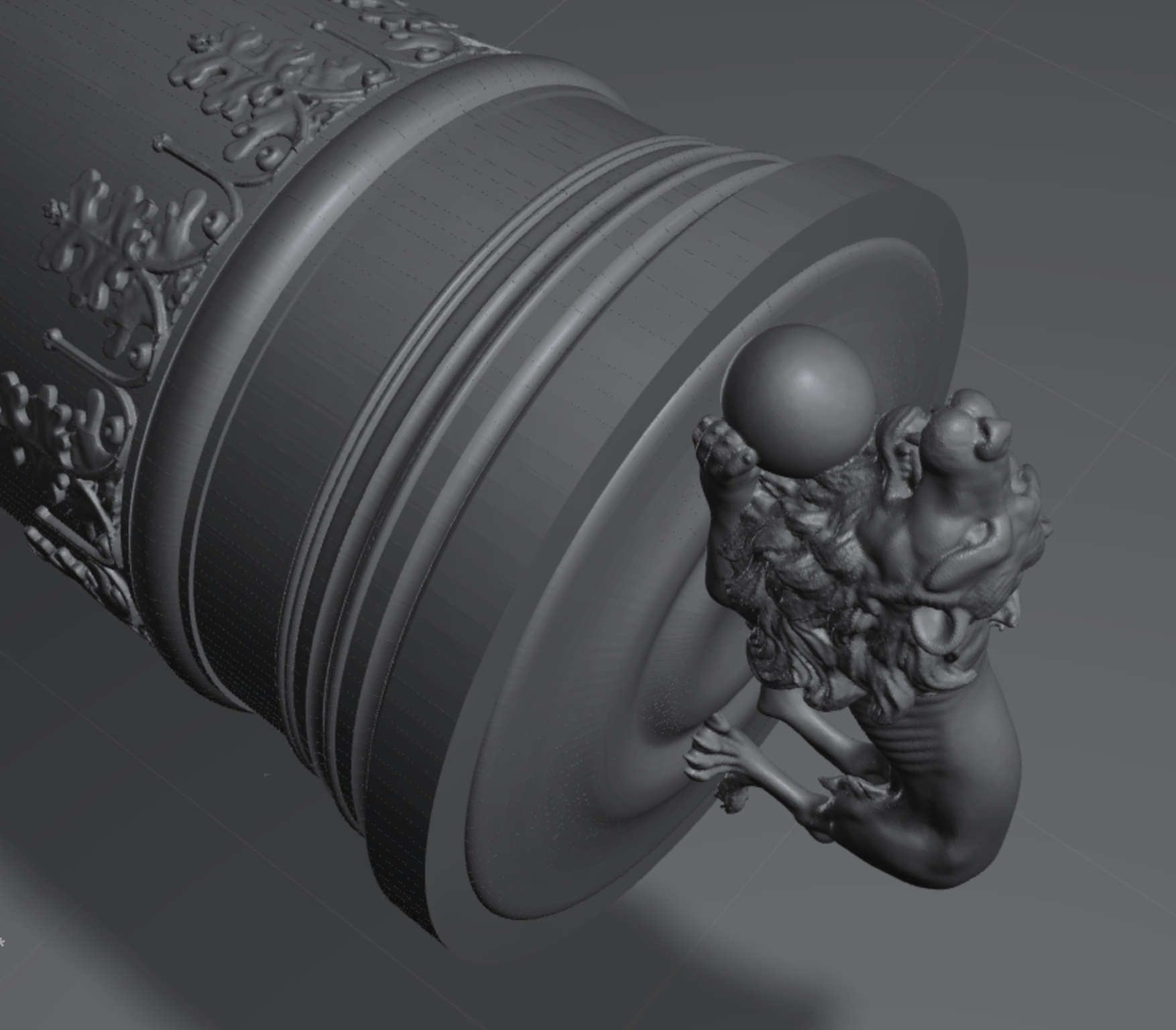
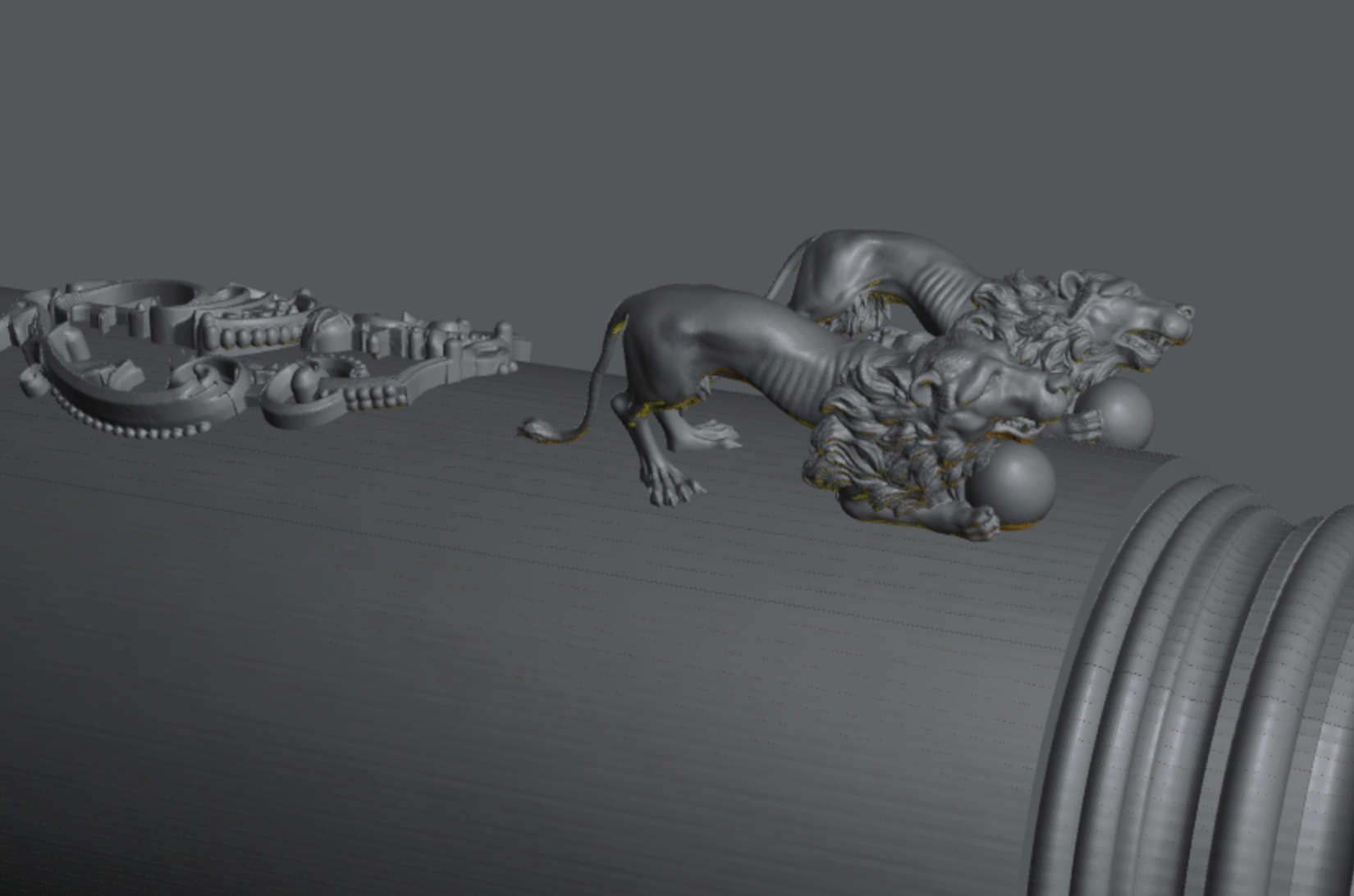
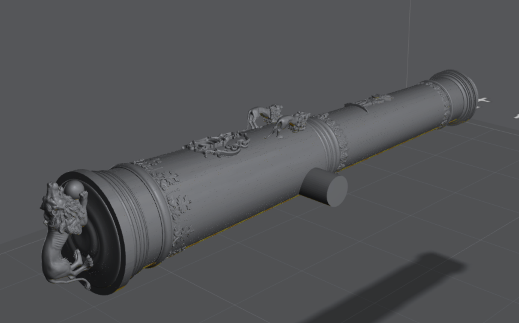
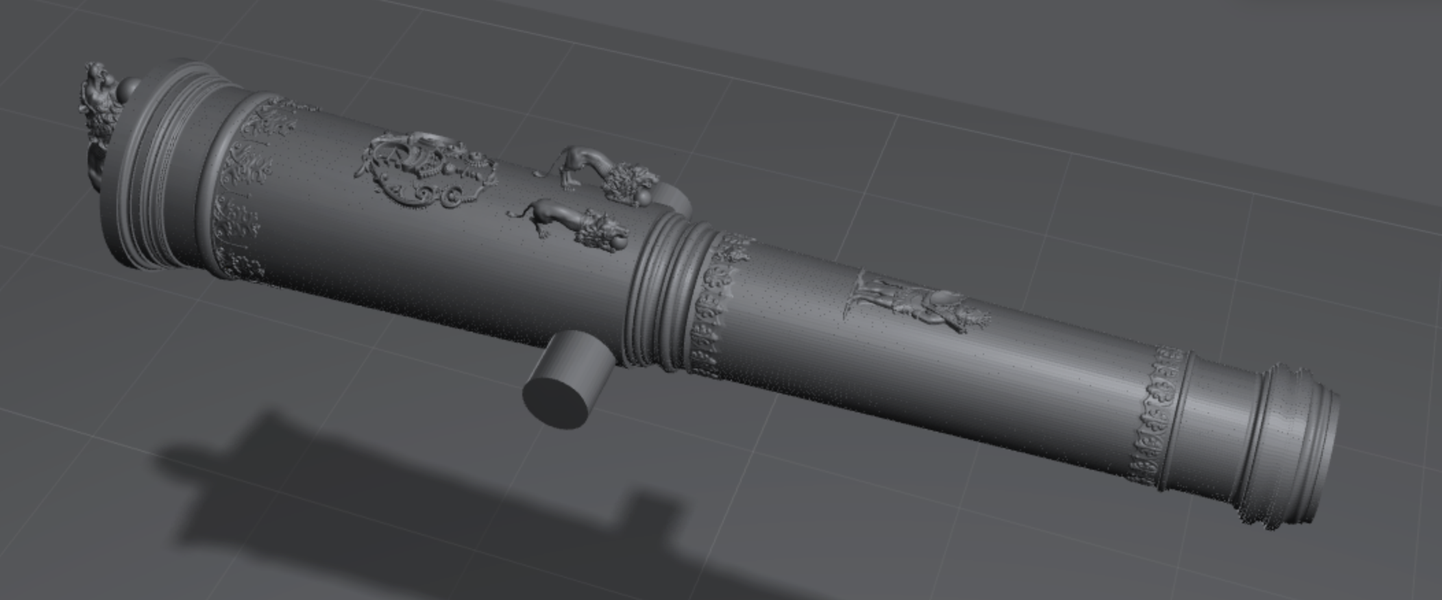
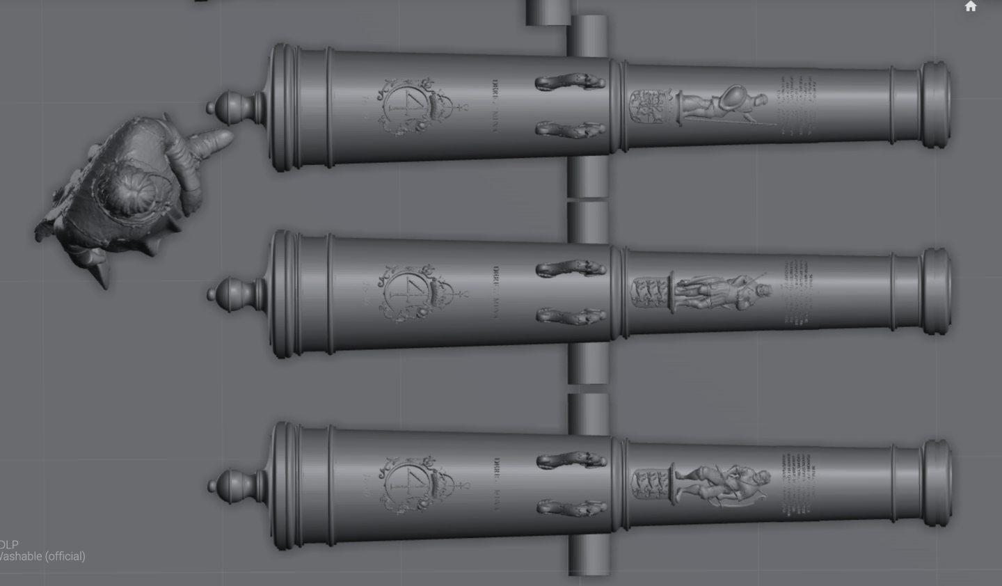
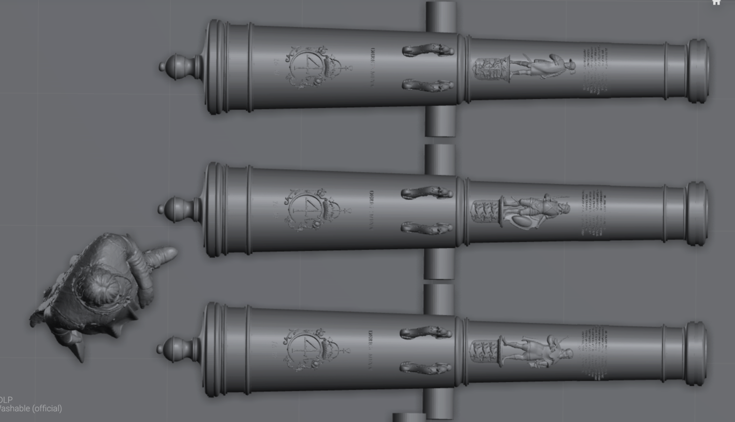
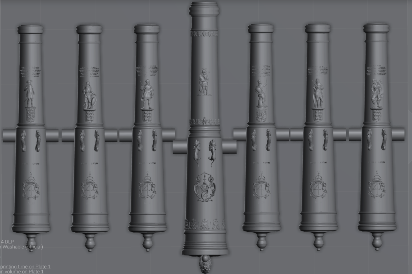
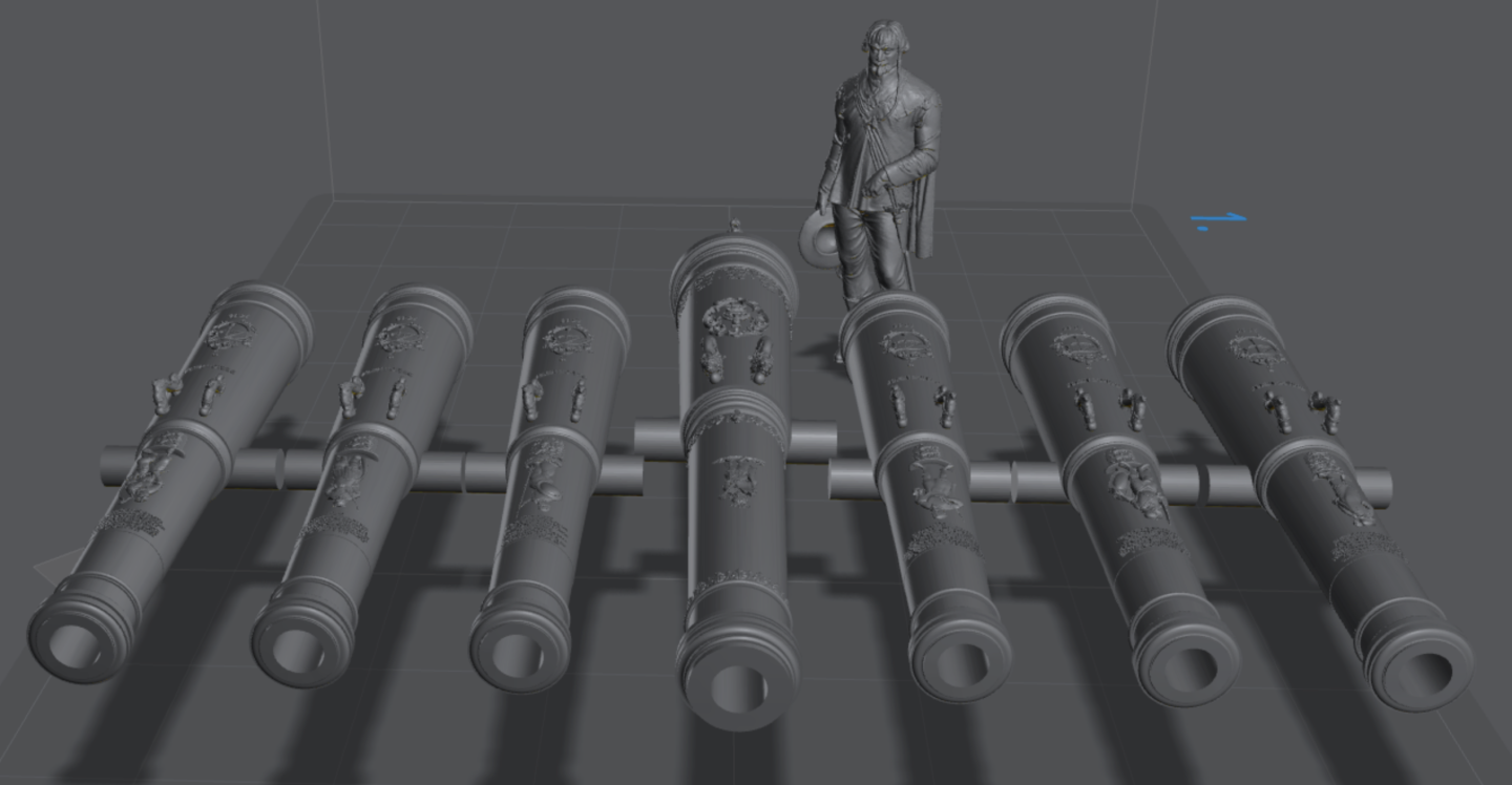
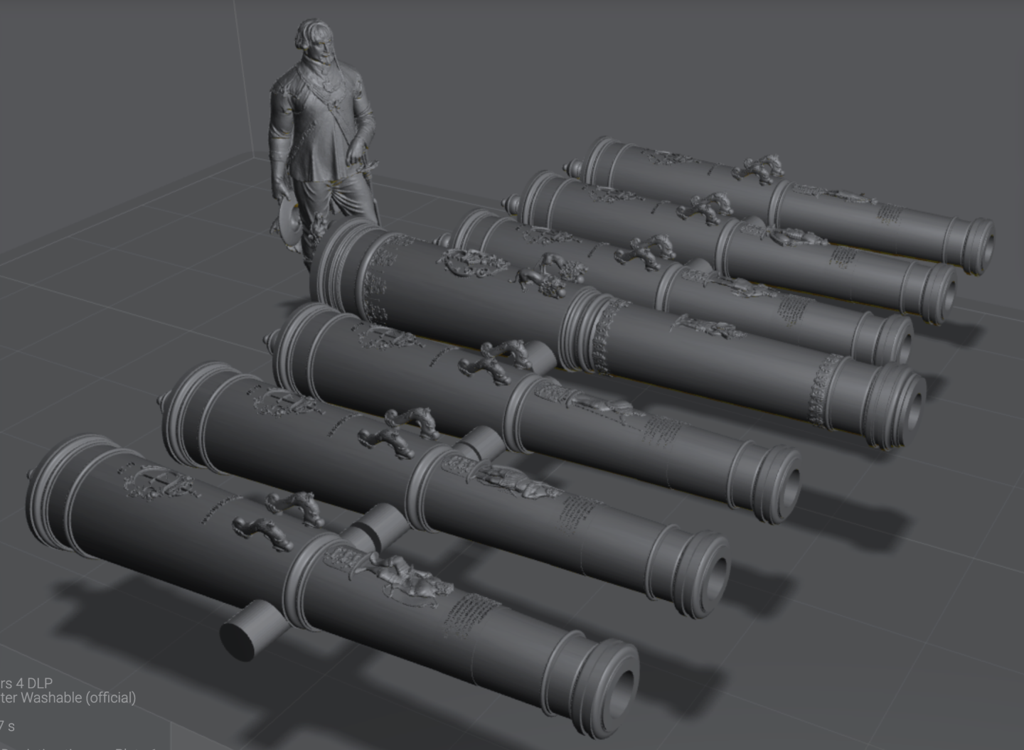
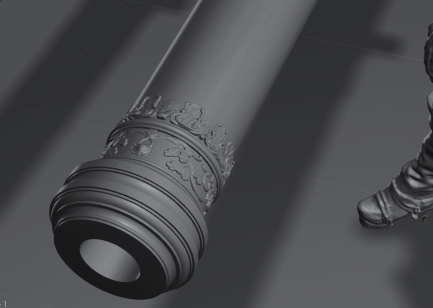
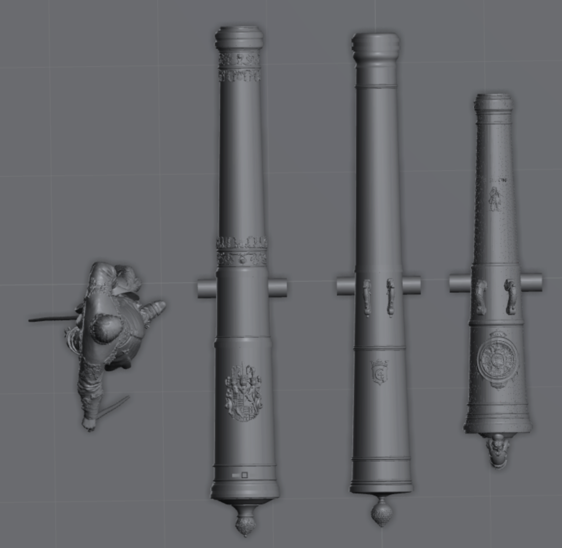
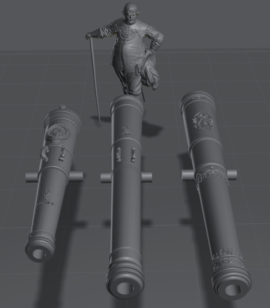
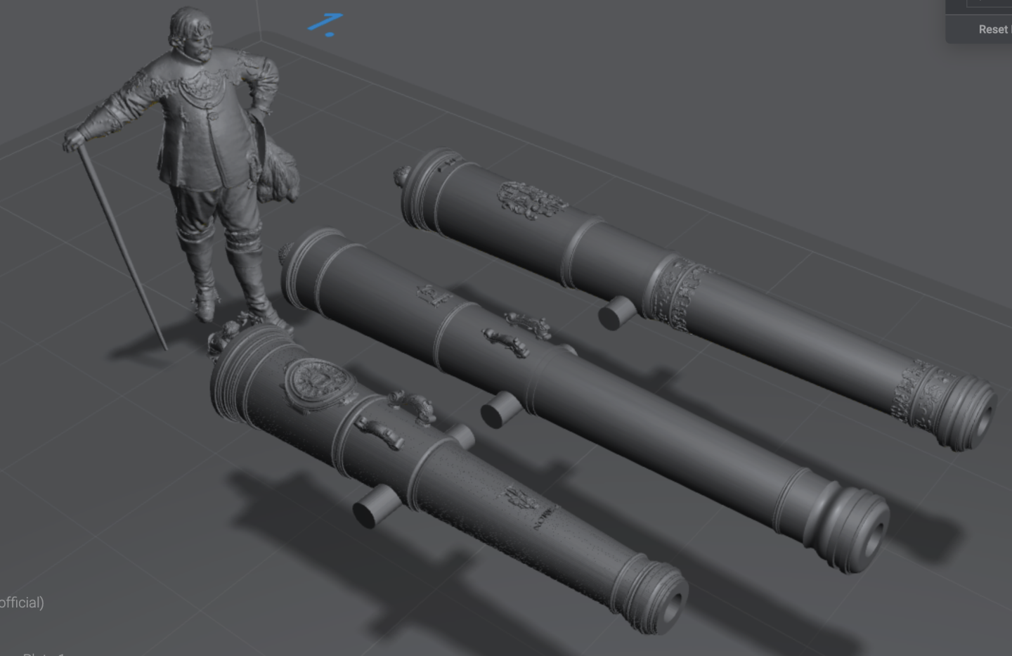
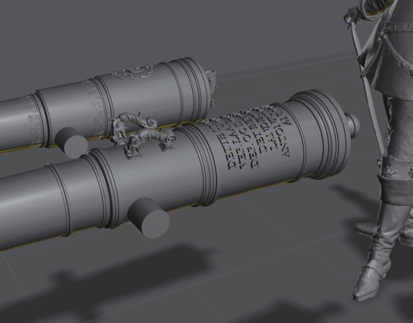
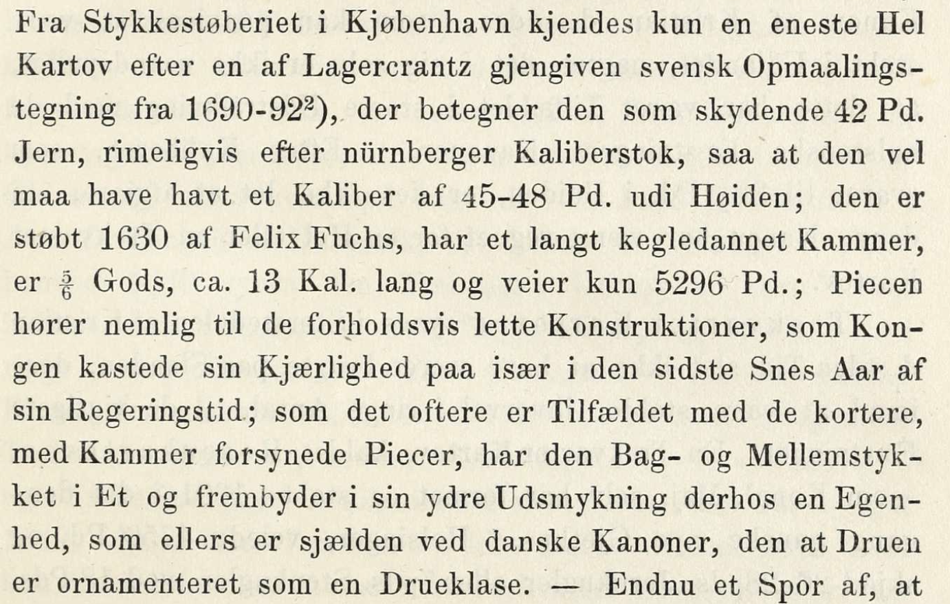
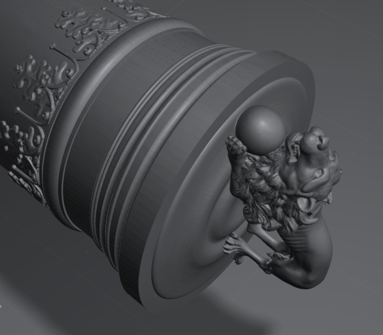
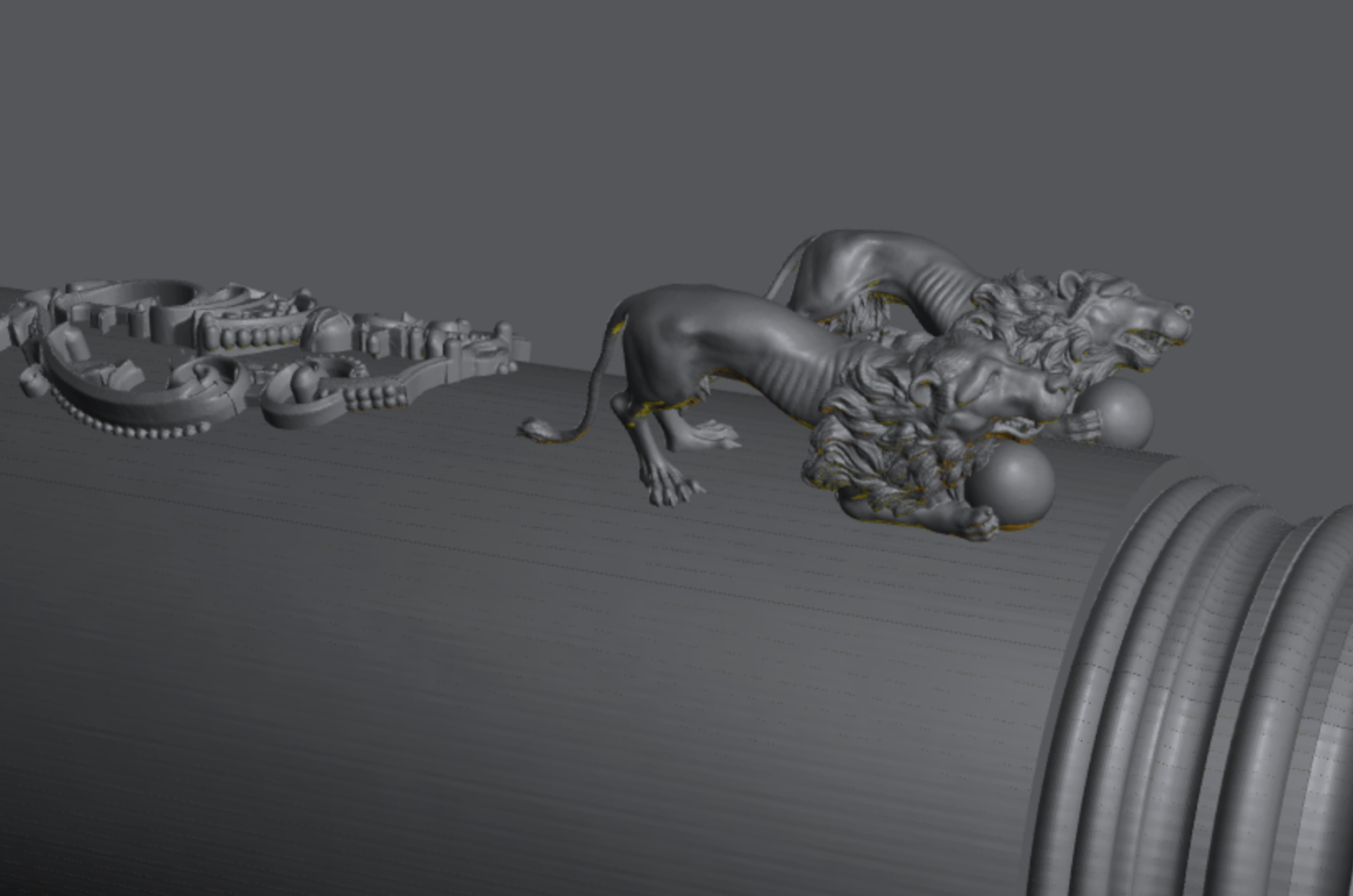
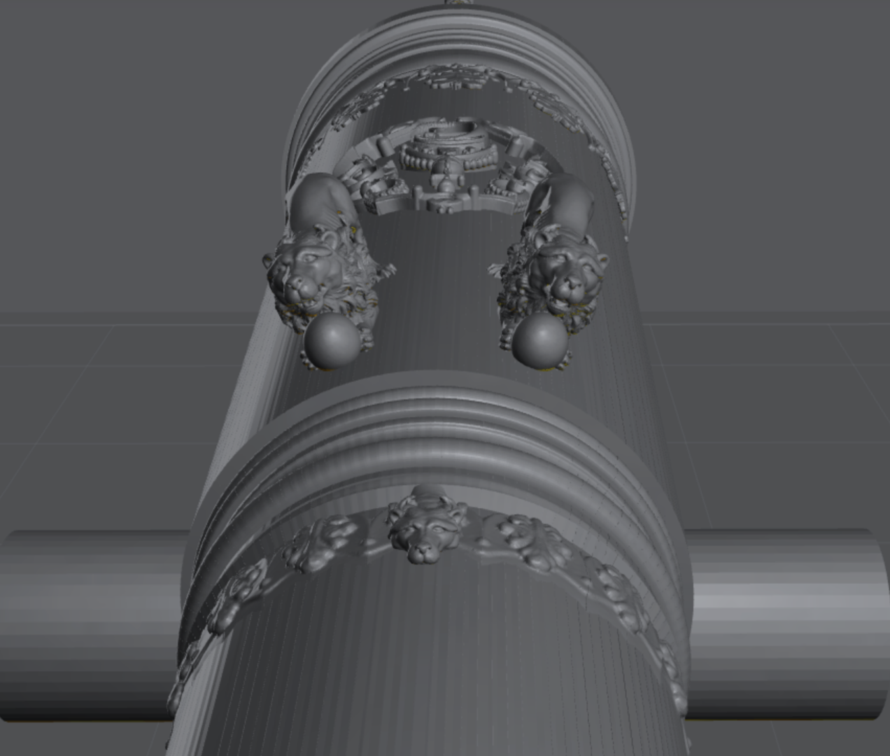
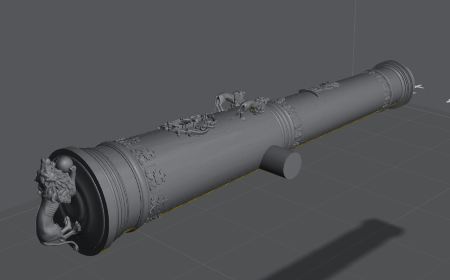
I have been spending the past few days using all of my monthly Meshy tokens in generating a bunch of assets for the cannons we have been discussing in this thread 😁 I am so happy this technology is coming right now - in my opinion, this is the perfect use of AI. So here's a bunch of images of the cannons I have prepared - I will post the STL files (those that are not too enormous) later, with a bit more detail and showing the drawings they are based on as well. As you can see, Meshy has also provided me with my very own versions of Christian IV for scale, inspecting the pieces that has arrived from the foundry 😅 These are based on portraits or statues of the King and are a remarkable close likeness for a 40 second AI generated model! First, two very different 4 pounders: Then a few 12 pounders, one of them very short, the others quite long: And last, but certainly not least, a series of 'Nye Konger' ("new kings") 24 pounders and a 'Løvekonge' ("lion-king" - also shown a few posts back). I believe this larger cannon is a trekvart kartove of around 5000 pounds weight as opposed to the other 6 which were 3200-3500 pounds halv kartover, and so would have been a 27 pounder. (and I think the King drank a bit from the fountain of youth for this session...): I know that the tiny text on the 'Nye Konger' would have been recessed, not protuding as I have it, but these are made to work at 1/64 to 1/32, and I don't think I can print recesses that small at these scales. I think this is a resonable compromise. The letters will be 0.32 mm tall at 1/32 scale... 🫠. I think they will at best be tiny bumps at 1/64 scale... time will tell, when I get to print some. I did 6 of the 'Nye Konger' as I just couldn't help it with the great reference material Waldemar has been providing: I thought it would be fun to have a few different options - in reality, they were all unique, I think! BR TJM


-
@Waldemar, thanks you so much! This does make sense - at least it is completely systematic and, which is more important, practical from a real-world use perspective. And while your numbers vary from Blom in the outer ranges, as you mention, they are close enough to still 'fit' the known nominal calibers for bore and shot weight. The table you made is really useful 😁
-
@Waldemar, where do you find these?: When I search on digitalmuseum.se, I can only find the Thelott drawings, not these. And these are interesting, even though they may be less fine and often have folds. As they carry the poundage designations we have been discussing. How do you search to find them? BR TJM
-
Thanks, @Lieste! It is interesting that this mixing of bore and shot weights is not that uncommon. I wonder why? Likely due to very confusing and mixed listings, also combining different pound standards in the sources. I believe that the most reasonable is that the Trefoldighed carried 12 pounders measured by the bore, which would mean 10 pound (Nuremberg) shots, even though the 24 pounders are listed by shot weight - they would have had a 26 pound bore acc. to the tables in Blom's work. It does not seem like the 14 pounders (16 pound bore) were really used as upper armament on the large ships - these were used as main armament for the lighter sub-40 gun vessels. BR TJM
-
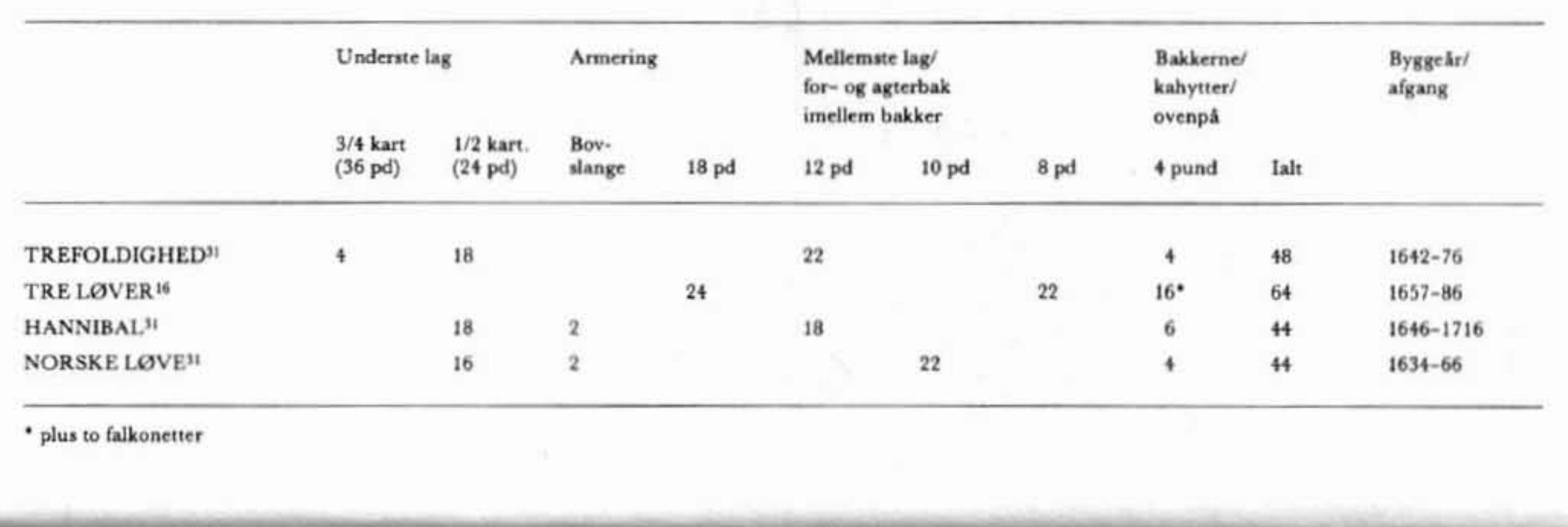
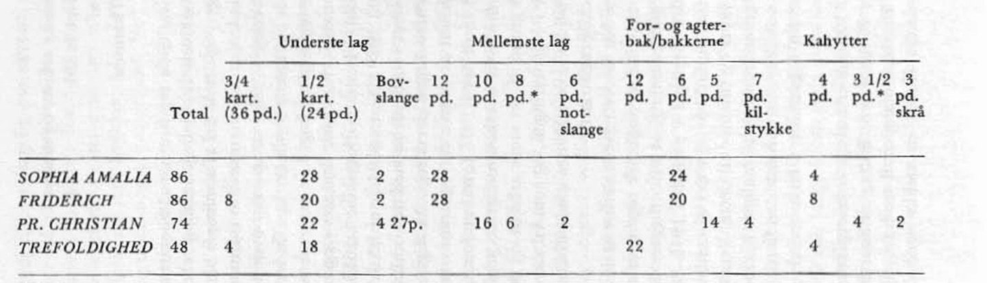
There are still some very puzzling things about these weights, actual and nominel. I am looking into the Armament of Christian IV's last main ship, the Trefoldighed. This is the one he famously commanded in the Battles of Lister Deep and Kolberger Heide. It had 22 gunports on the main battery and 22 on the upper battery and then a number of smaller ports on the qarterdeck poop deck and forecastle. The lower deck ports were dimentioned for 3/4 kartover and the upper deck ports for 1/2 kartover. People have therefore assumed, that since a hel lartove is 48 pounds, the Trefoldighed must have carried a massive armament of 22 36 pounders and 22 24 pounders. This would have made it incredibly powerfull! You can find this kind of lineup reported on the Danaih Wikipedia. It is not true though. One of the most capable Danish naval historians of modern times, Niels Probst, writes in Marinehistorisk Tidsskrift in vol 3 1984 that Trefoldighed carried four 3/4 kartover and 18 1/2 kartover on the lower deck and 22 12 pounders on rhe upper deck, and a few 4 pounders on the castles: He is quoting P. Holck for these numbers and it also agrees with what Blom writes: only three ships in 1652 carried 3/4 kartover, one of them was Trefoldighed with 4 pieces. The same is quoted in Marinehistorisk Tidsskrift vol 1 1981: But this it where it stops making sense. Probst calls the 3/4 kartover 36 pounders (this was why I was looking for at 36 pounder!), but it is clear from Blom that by the time of Trefoldighed, the 3/4 kartover was 27 pounders. I am not comfortable with what seems to be an error on Probst's part! Also, he mentions that the upper deck carried 12 pounders, but 12 pounders were not present in the armoury if we go by the nominal weights!: There are many cannons with a 12 pound bore though! They would nominally be 10 pounders. Would Probst mix bore and shot poundages when specifying the armament? That does not sound credible. Again, I am not happy suggesting that Probst got this wrong! He surely must have known Otto Bloms work! Then there is the possibility that he was quoting not nominal shot weights, but bore or actual shot weight in Danish pounds? But this does not fit either! It would mean the largest 4 guns would be hel-kartover, and Blom clearly says these were 3/4 kartover of 27 pounds. There is simply not one set of measurements that support 36, 24, 12 and 4 pounders! The most reasonable to me is 4x27 pounds, 18x24 pounds and then either 22x10 pounds or 22x14 pounds. How to settle this? I normally trust what Probst writes, but I cannot make it fit. Is there something combining the Swedish and Danish sources that can make this make sense? If anyone has any insights or suggestions, I would very much appreciate it!


-
Thanks for explaining this in detail! And what a further complication with a shift of scale right then! I totally see the arguments, but I can't reconcile the conclusion on the 42 pounder with the other images as well. If the poundage designations on the Swedish drawings were following the 1686 post-reform convention, then all the 24 pounders would actually be nominal 26-27 pounders in the Danish Nuremberg klassification system, firering actual 24-25 Danish pound shots. And this just does not fit with the known poundage of these comon calibers: we know these were nominal 24 pounders (Nuremberg 'talstok' wise) with a 26 pound bore (again, on the Nuremberg talstok), firing 22.4 Danish pound shots. It seems to me, that the measurements on the Swedish drawings for poundage must be from the old Nuremberg scale, which is identical to the one used in Denmark. I see it this way because we have the full inventory from 1649 with confirmed dimentions - not just infered from the Swedish drawings (with a potential uncertainty on the scale used), but based on measurements on actual cannons which confirms these - Blom mentions this in the text. Does this make sense? I may well be wrong! But this makes the most sense to me right now 😅. And i truly appreciate your continued inputs to this @Waldemar, and I am afraid I may seem ungrateful for challenging your well argued/researched points! I am just trying to make sense of it all! 😄

-
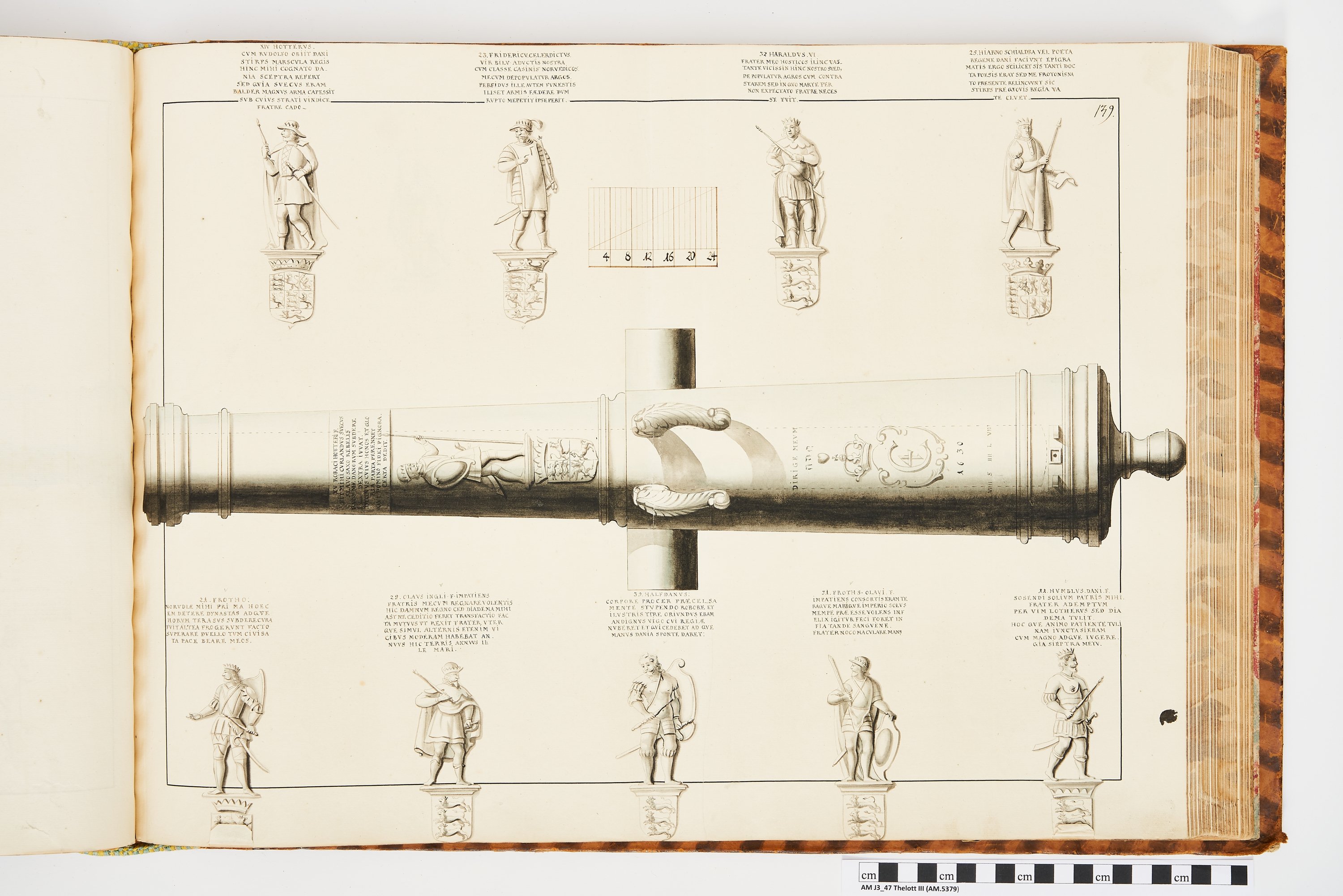
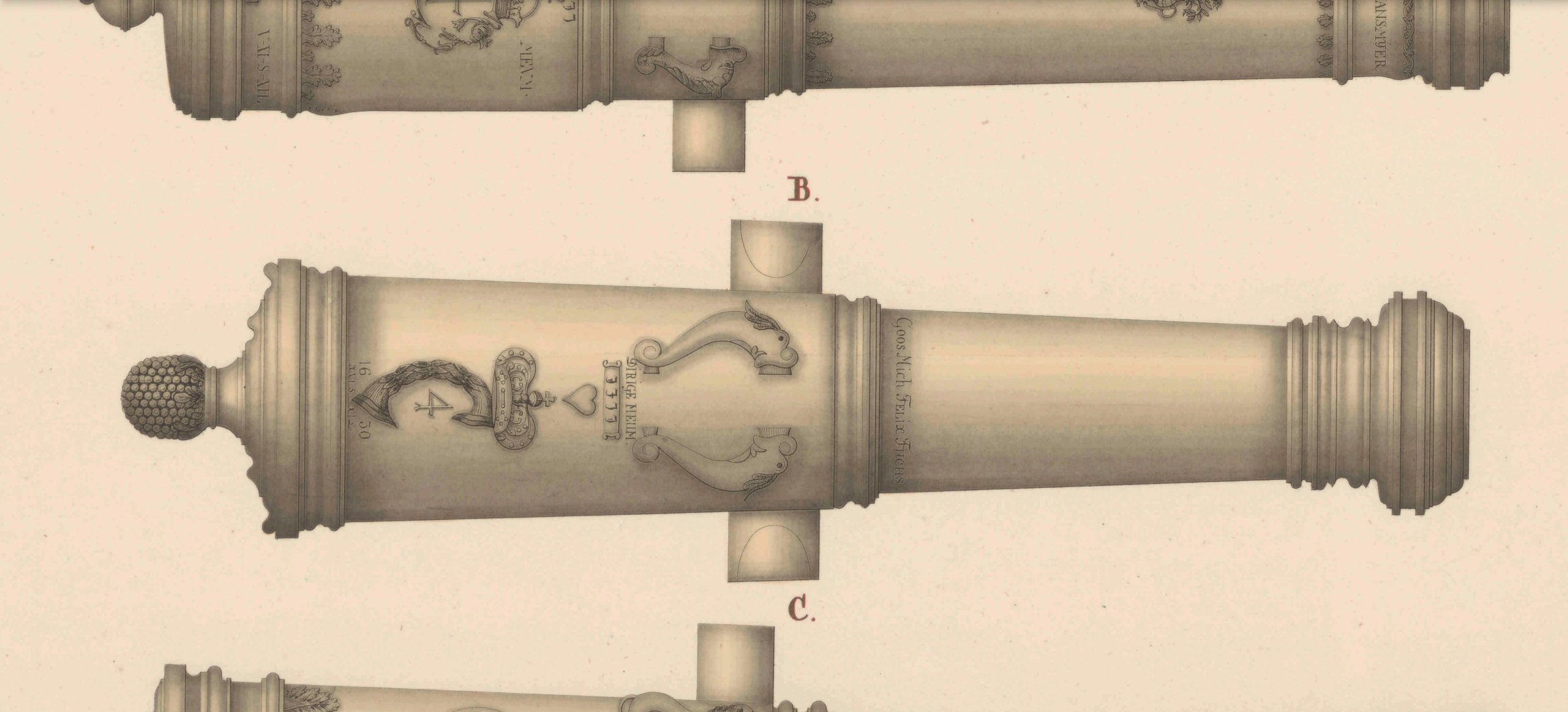
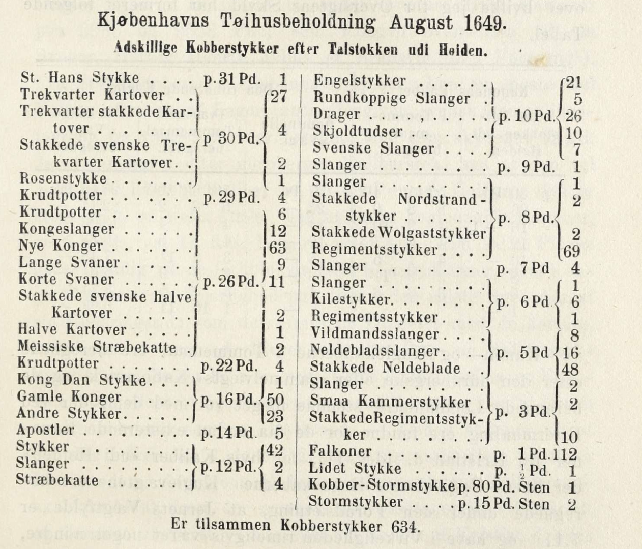
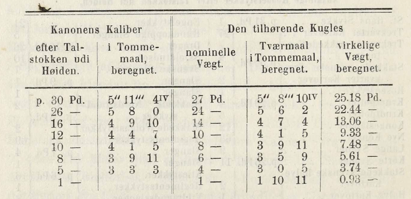
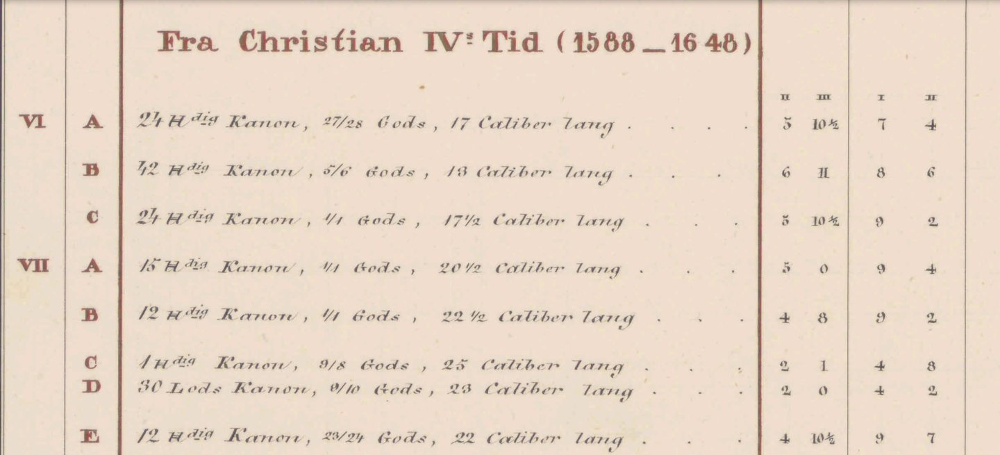
I truly appreciate this @Waldemar, thank you for taking the time to dig into this and help me out! I had not come across Otto Blom's book - for reference, it can be found here, all out of copyright and free to use or reproduce: https://www.kb.dk/e-mat/dod/11342801000A.pdf I had not before seen the point about the Nüremberg pounds, which are the basis for the measurement of the guns bore and shot sizes. even if this is in Danish, it is 150 years old and hard to read due to the long and complicated sentences - much more like modern german i think - and because of the rather unstructured way the arguments are put forth - more like a strain of thoughs than a well planned text. I will try to give a brief recap of some of the most important points I have found: The cannon's bore size and the shot size was based on a so called 'talstok' (number stick), showing the diameter of the various bore/shot sizes. However, this was based on the Nüremberg pound, not the Danish pound! The bore of the cannon were naturally larger than the shot diameter, to allow for some windage and Blom suggests that the nominal bore was rounded up to the nearest pund park on the 'talstok', where the shot size was rounded down. This meant that it was common to have a cannon with a 26 pound bore ("pund udi høiden" = pound in the height = the bore diameter) that fired a nominal 24 pound cannon ball. Now, to complictate things, the daily measurements of shot weights were done using the normal Copenhagen pound ( 1 pund = 0.498 g). Blom suggests that they clearly new the difference between the Nüremberg pound used for the bore and shot classification and the actual nominal shot weight in Danish pounds, but that it was simply not a difference that was taken into account in practice! The following is a nice little table showing the difference between bore, nominal shot weight and actual shot weight: So, a 24 pounder (halv kartove) would have a 26 pound bore (5"8'0IV diameter) and fire a 22.44 Danish pound shot (on average!) with a diamter of 5"6'2IV. This difference between Nüremberg and Danish pounds can be seen from account lists where the nominal shots are listed, but the total is also weighed. A delivery in 1683 is quoted for a total of nominal 114440 pd, but weighed in at 99736 Danisg pund - a difference of almost 15%. Now, let's have a look at the common sizes - these are sorted by nominal bore sizes: While there are many strange sizes, the eight from the previous table are by far the most predominant: 30, 26, 16, 12, 10, 8, 5, and 1, corresponding to nominal weighs of 27, 24, 14, 10, 8, 6, 4 and 1 pounds. The first two are the trekvart kartoves and halv kartoves respectively, though the kartove designation refers to the size and weight of the gun, not the shot weight, so there are quite som vararity within the kartove klasses - but by the 1630's and definately here at the end of Christian IV's reign, the 27 pound trekvart kartove and the 24 pound halv kartove was the common ones. With regards to the 42 pounder from the Swedish and Grunth drawings that we have discussed previously, this particular piece is mentioned specifically in the text: This is described as a hel kartove with a Nüremberg shot weight of 42 pounds, and likely a bore caliber of 45-48 pounds. Here, Blom mentions that the Swedish drawing is presumably using the Nüremberg measurment as well, which might seem surprising! But he mentions in other places that this system was also used in Sweden for the nominal cannon/shot clssification! But I also think that the Swedish and Nüremberg pounds are almost identical - it seems to be not the 369 g, but rather a 424 g Nüremberg pound that was used - one that is 15% smaller than the Danish pound. I guess this means that a cannon mentioned as a 24 pounder (or, as here a 42 pounder) on the Swedish drawings, is also a 24 pounder in Danish terms, as they use the same scale (Nüremberg) to classify the guns, but then use the local weight units when they weigh off the cannon or balls. But as mentioned, a nominal 24 pounder, would have fired a 22.44 pound shot (or anything between 22-23 pounds, really...). This also explains why all the well known 'Nye konger', that are known to be (nominal) 24 pounders, are also labelled as such on the swedish drawings. So my interpretation is that, yes, the 42 pounder hel-kartove is a 42 pounder, in both Danish and Swedish terms - it would have fired a 36 Danish Pound shot, but it would have been called and classified as a 42 pounder. In Swedish terms, it would actually have fired a 42 Swedish pound ball. I will look into more, as there are still some strange things when looking into the armament of certain ships, and I will be back with more soon. BR Thorbjørn

-
Hi Matthias, At some point, I will definatly print this - likely also in 1/32 for a display model! I am deep into researching the artillery of Christian IV's time in preparation for a future project, but unlike the later artillery the measurements are all over the place, as the current conversation with Waldemar clearly shows! But I am slowly getting the hang of this and at least i can read the sources! All of these cannon depicted by Grunth are bronze. At the time, they called these 'metal' pieces as opposed to 'jern' (=iron) pieces. Ther heavy artillery at the time (the first half of the 17th century) were genrally bronze, Iron only really becomming prevalent in the late 17th century and only took over completely by the 1750's or so.
-
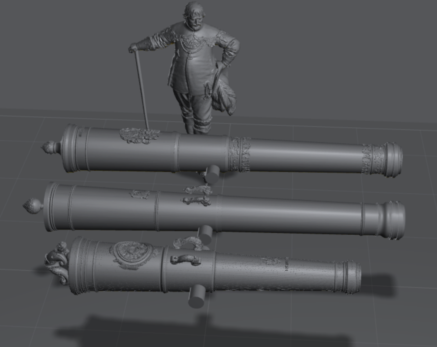
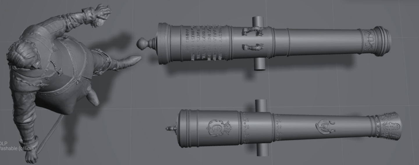
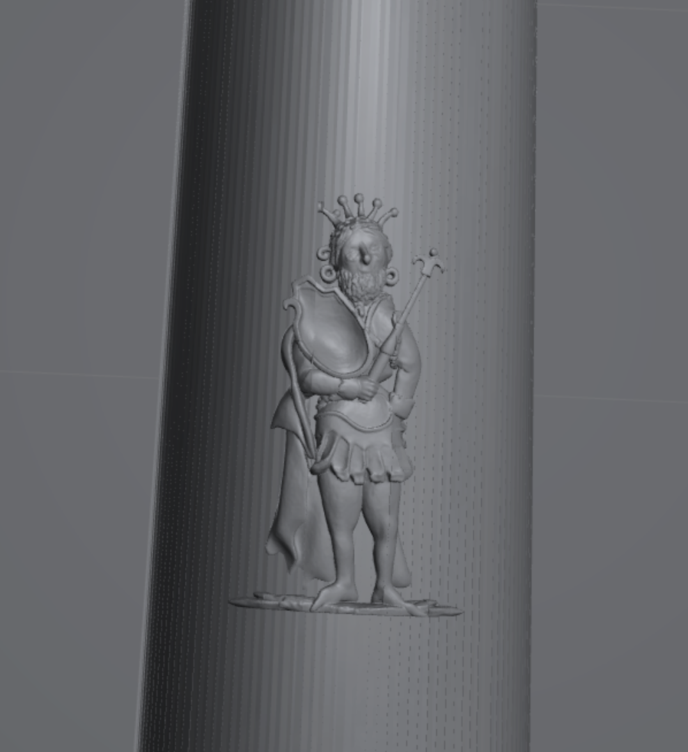
Thank you for looking into all of the @Waldemar, it is really interesting. I am not sure what to make of it, and while what you say makes sense on it's own, there are some things that does not fit what we otherwise know: We know that the most common shot weight for the larger warships of this time was 24 pounders - most common second battey armamament was 12 pounders with 6 or 4 pounders on the castles and/or cabins. We also know that some of the larger series of 'halv-kartover', 24 pounder, were 'De Nye Konger' (the New Kings) of 24 pounds shot weight (as oposed to the 'Gamle Konger' - Old Kings' from 1603-1607 which were 14 pounders) and the Apostles which were 12 pounders. Many of the 'Nye Konger' are in the collections, your second to last set above is a so called 'Løvekonge' - a lion-king - which are known to have been a Danish 24 pounder, but it is also labelled as a 24 pounder in the Swedish drawing! We see many cannon labeled as 24, 12, 6 and 4 pounders here which lead me to believe that these are the original Danish shot weights, not the Swedish ones. Otherwise, everyone from Grunth to modern experts like Barfod and Probst would have it wrong! If the poundage was Swedish, these would be strange Danish measurements of 20.5 pounders and 10 pounders, not calibres we find very often in the sources! I agree that it is strange that the Swedish drawings would quote the Danish weights, so there is mystery to be solved here, but if the measurements were Sweedish, I would have expected numbers like 28 pounders and 14 pounders to be prevalent, not 24 and 12, which look like the original Danish weights! I am truly not an expert here, and I am just trying ro reconcile the sources I have, mainly N. Probst, "Christian d. 4.'s Flåde" and various writings of his in Marinehistorisk Tidsskrift. Incidently, I actually made the 3D model of the aforementioned 'Løvekonge' 🙂 : Meshy did a fine job of making assets from the Grunth drawings 🙂


-
Very nice information, thank you! This makes your theory quite plausible, I think!
-
I am not sure the logic holds. I agree that this is a possibility, but it relies on the assumption that Grunth copied the Swedish drawing. Do we know this is the case? Grunth's drawing fits perfectly with a 42 pounder, from a bore size PoV. But of course that would be the case if the calibre is the only unit of measurement used to make the drawing. And he just assumed the 42 pounds was the Danish measurement. Regarding the weight, I end up with close to 2500 kg based on the volume of a 3D modelled version. That is closer to Grunth's measurement for the weight, but somewhere in between your two calculations. I am not sure how to settle this definately. Mind you, I am not saying you are not right here, I am just saying that I cannot prove it with the volume calculation.
-
@Waldemar, it seems the canon is actually a 42 pounder: it is also depicted in the Grunth collection: It is extremely short, only 13 calibres. Even a 24 pounder at 17-20 calibres would be longer overall, like it's neighbors on the page above. But it seems the 42 pound designation on the Swedish drawing is actually the Danish poundage. The search for a C4 36 pounder continues! 😅

-
Welcome!
-
Fantastic,thank you so much! Where is this image from? Is it a physical book, or do you have a link to the source?
-
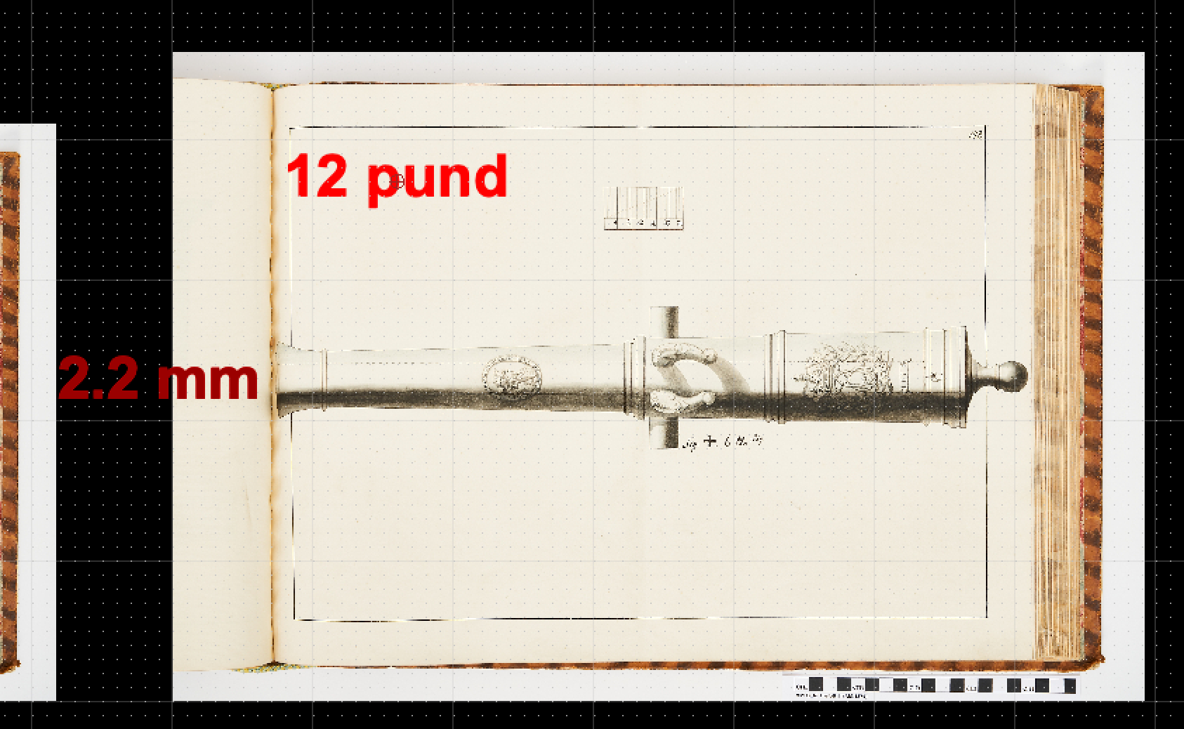
But perhaps I am wrong.... This one appeas to be a 12 pounder if I scale as described above, but it clearly states on the drawing that it is a 6 pounder 😅 hmmm...

-
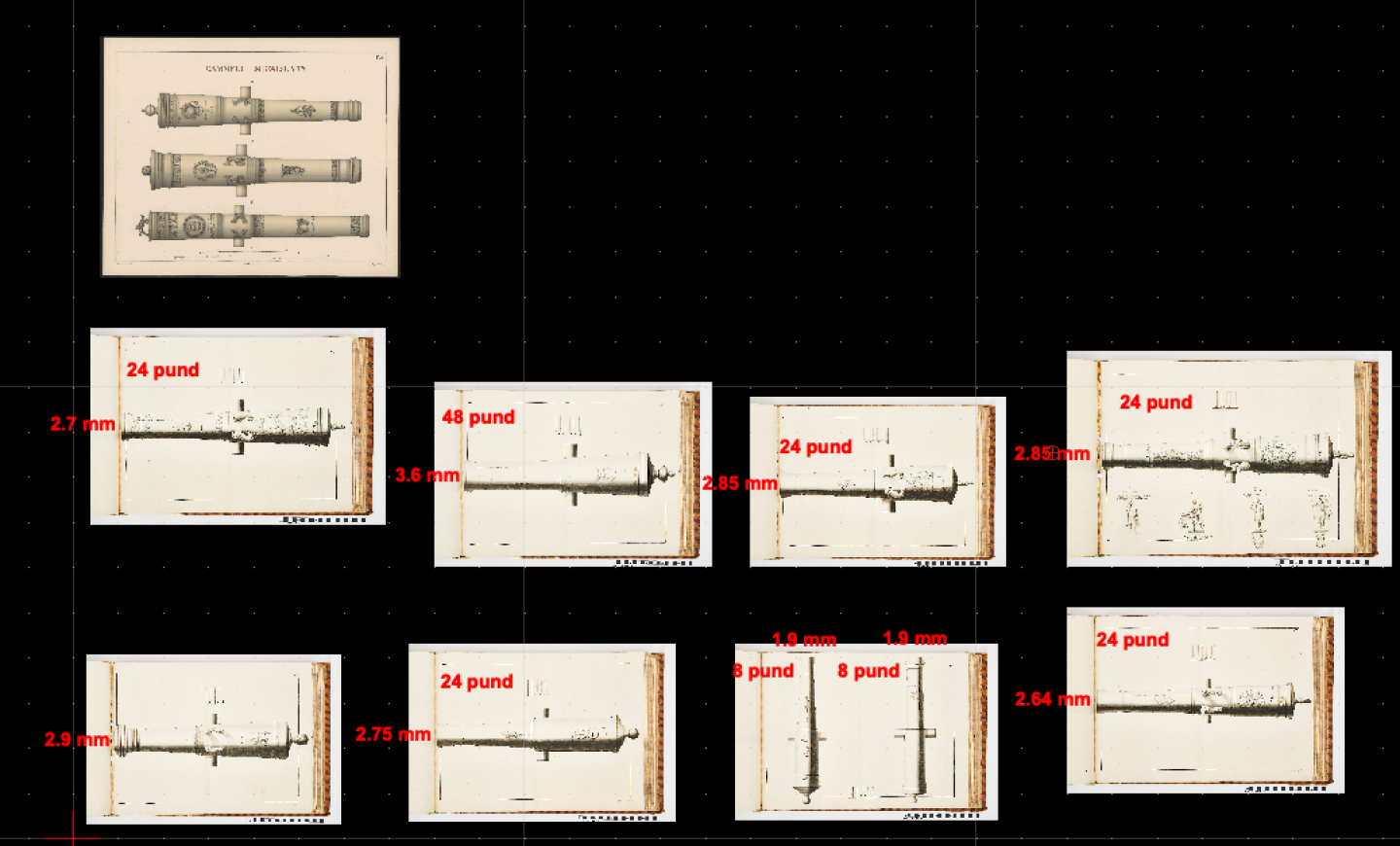
Hmm, I know it was common to measure the length of the bore in calibres, but I don't think the scales in these drawings are abitrary - I agree that the guns are scaled to the size of the paper, but the scale is matching as well. If I scale drawings (at 1/64 scale just for my convenience) to the known 24 pounder from Grunth, and then scale all of Thelott's drawings to that one, I get a very consistent pattern: all the ones i would guess would be 24 pounders (a well known series called 'konger' = kings) all end up with close to the same bore diameter (2.7 cm at my 1/64 scale - plus/minus 0,15 mm). I have also found what must be a 48 pounder and some 8 pounders. So I do think the scale is somehow absolute and can be used to infer the shot size from the indicted bore diameter. But I have not found any 36 pounders. and I think I have looked into the ones that was plausible. But there are still so many nice patterns of other sizes, so it is really a great collection!
-
I will probably not go through all of them, but the ones I do find the poundage of, I will report back on. But the scale in the drawings are puzzling. It goes from 0 to 24 in increments of 4, so I assumed the unit was Swedish inches, and thus the total would be two Swedish feet. But that does not fit at all! I have a pattern of 24 pounder which is depicted both by Thellott and Grunth so I can make a direct comparison there snd use that for the rest of the Thelott drawings. The difference is huge: if I assume Thelott's scale is Swedish inches, I have to reduce to 0.603 scale to fit the Grunth drawing! Was there a unit of length used at Thelott's time that was 0.603 of a Swedish inch? Around 14.9 mm?
-
Wow, thanks! It looks like there is another 70 or so Danish artillery pieces in that collection! Thanks! I will hunt for a 36 pounder from Chr. IV's time, I have not found one yet in other sources 😁
-
Yes, I am running with 2px 30% AA but to be honest, I don't see much difference whatever I try with regards to AA. I clearly see the blurring on the slices, but no real effect on the print. But AA must be highly dependent on dialing in the correct exposure, otherwise 30% exposure quickly becomes much more in reality. And that is one of the benefits of the DLP printer I have: there is almost no pixel bleed, so exposure is not very critical, as anything above 'enough' will give good prints. I guess I should try to play around with this a bit to see if I can optimize it a bit.
-
That still sounds very interesting, do you have a link to work in the Swedish archive?
-
Very happy to help! I had also seen low res reproductions in works by Niels Probst and was looking for the originals - they are available from antique bookshops, but at very high prices. So happy we have a fantastic public library infrastructure! I also afterwards found the non-shaded version already scanned at KB: https://soeg.kb.dk/discovery/fulldisplay?docid=alma99124201153505763&context=L&vid=45KBDK_KGL:KGL&lang=da&search_scope=MyInst_and_CI&adaptor=Local Search Engine&tab=Everything&query=any,contains,metalskyts&offset=0 But the shaded ones are prettier 🙂
-
I have tried in Blender as well - the problem is that most of my polygons are in the ornaments, and very few are in the cannon, even though it takes up most of the surface. But when I re-mesh, I get a more even distribution of polygons, which means the drop in quality on the ornaments is huge and I get a lot of extra polygons on the cannon that does more bad than good! Even with adaptive voxel re-mesh. I get to 1.5 million polys, but the drop in quality on the ornamets is 10-fold! I had not! but it gave a huge saving of around 50%, so here it is! Danish 36 pdr - 1733 - C6 1-64 scale.stl.zip I don't why I didn't think of that - thanks!