HOLIDAY DONATION DRIVE - SUPPORT MSW - DO YOUR PART TO KEEP THIS GREAT FORUM GOING! (Only 36 donations so far out of 49,000 members - C'mon guys!)
×


cdrusn89
-
Posts
1,915 -
Joined
-
Last visited
Content Type
Profiles
Forums
Gallery
Events
Everything posted by cdrusn89
-
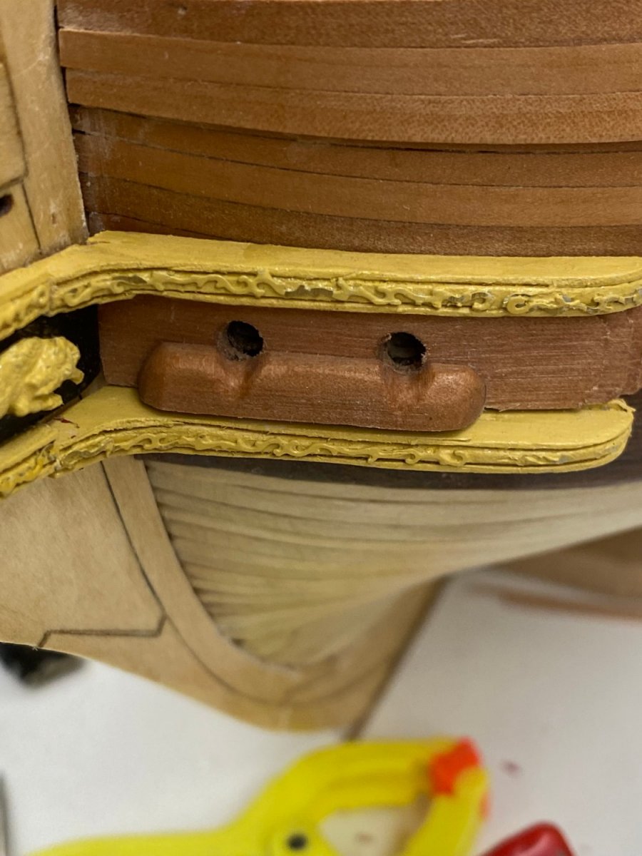
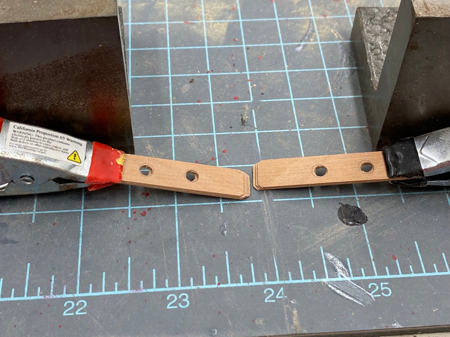
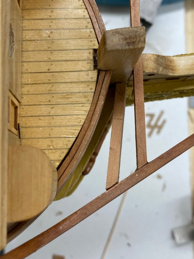
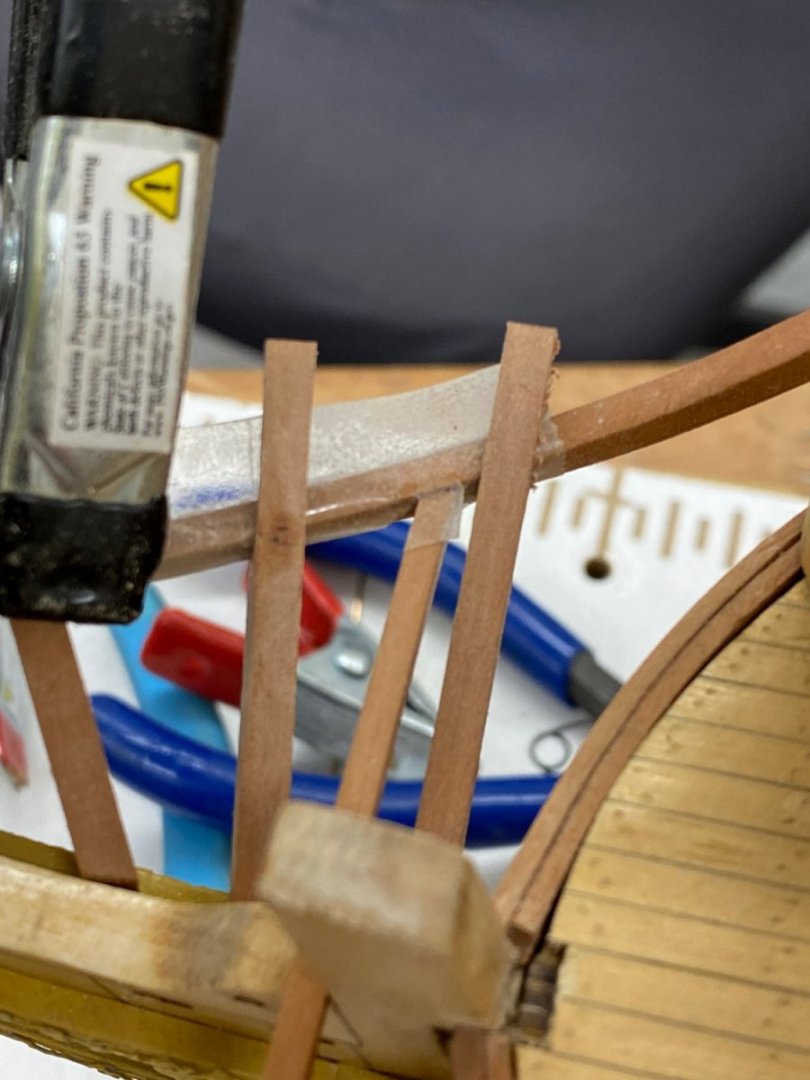
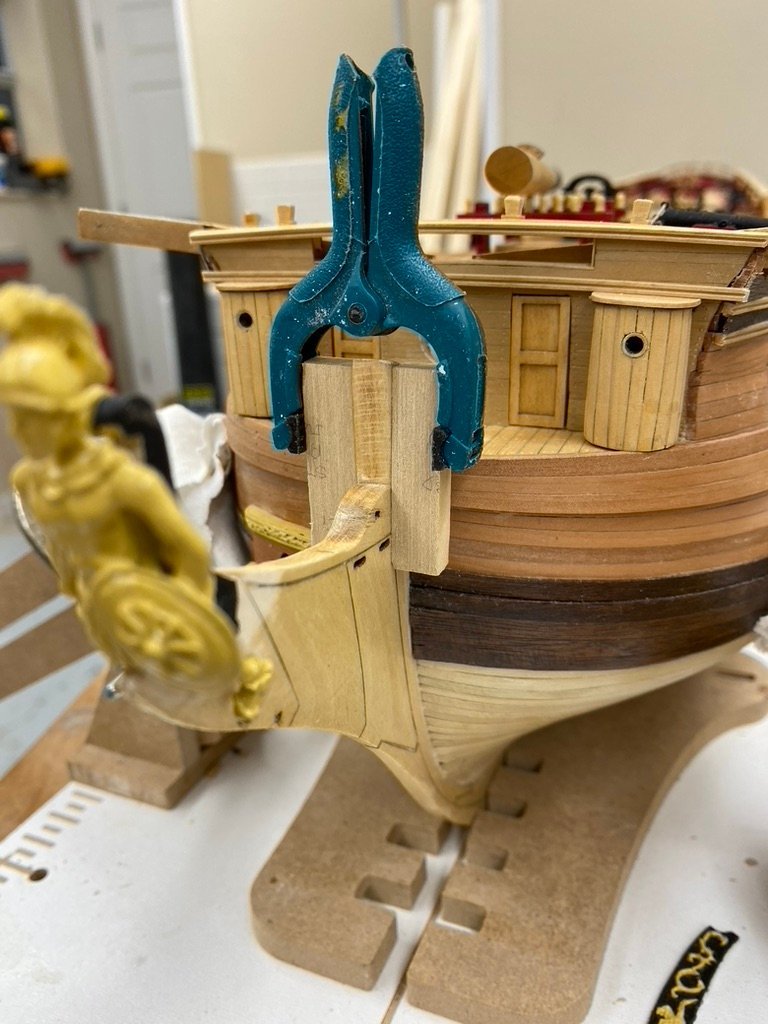
 The first of the "new" head timbers with the 1/16" gap to the top of the head rail. This one was pretty easy to fabricate. As the upward angle gets steeper as the head rail gets closer to the stem the interface to the cheek/stem becomes much more complex - slopes or champers is all three dimensions. Much fun with sanding sticks to come.
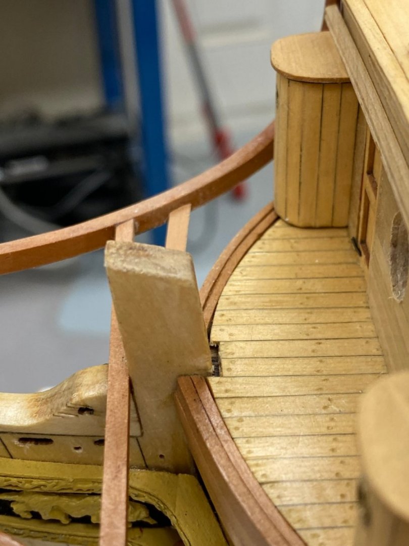
- 370 replies
-
- 1
-

-
- Model Shipways
- Confederacy
- (and 1 more)
-
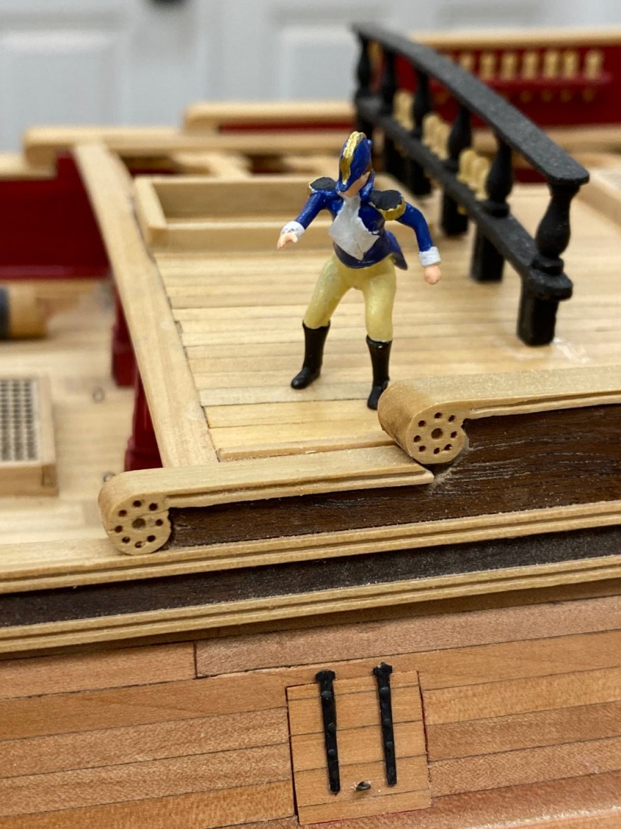
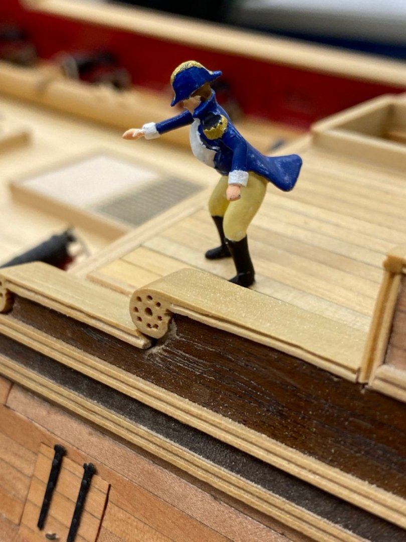
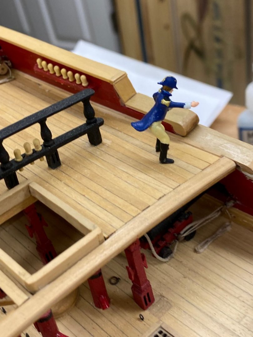
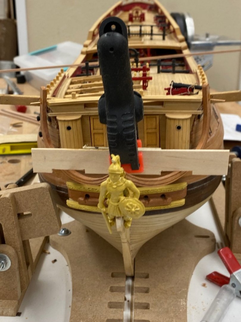
I have not previously put figures on any of the models since figures (of the proper scale) are now available through the NRG Store I decided to get a couple. It turns out that there are only two US Officer figures available so I got both of them. Here is one of them (1/64th scale), painted (correctly I hope) on the forward end of the quarterdeck.

- 370 replies
-
- 2
-
-
- Model Shipways
- Confederacy
- (and 1 more)
-
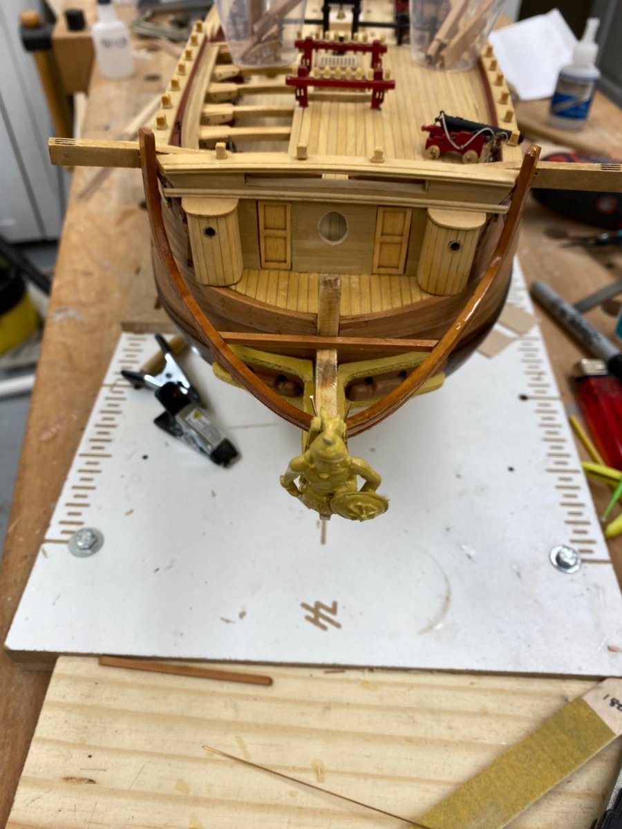
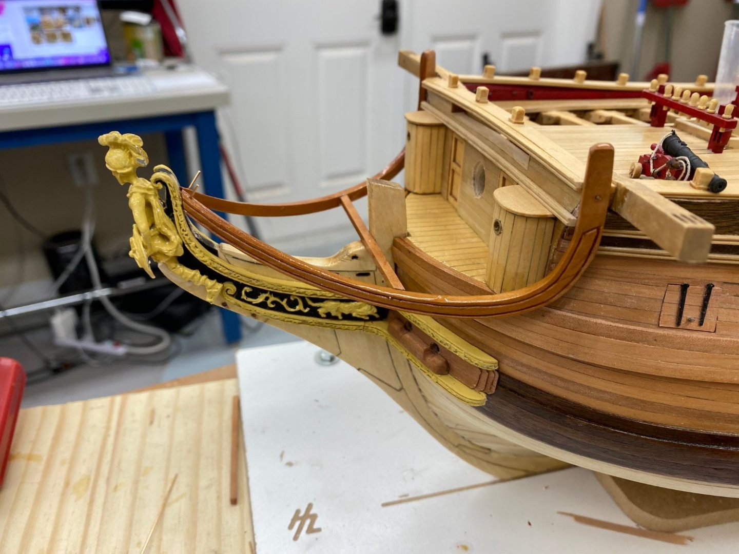
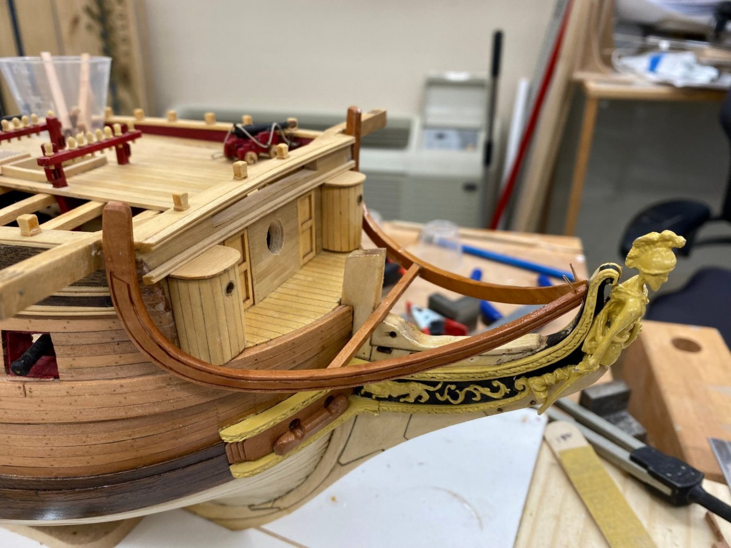
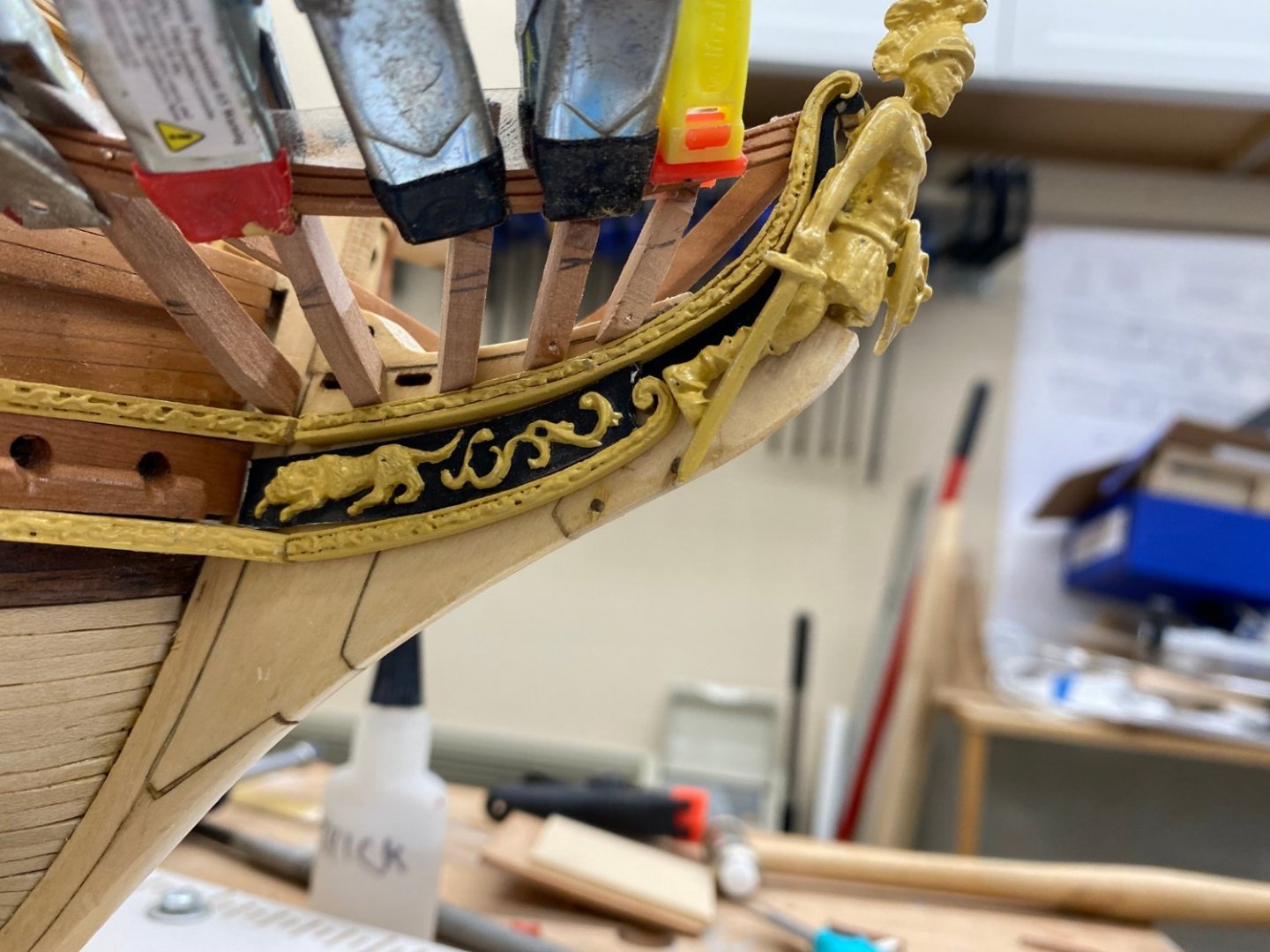
Head rails are back in place and the head beam as well. I used the .025 phosphor-bronze pins at both ends of the head rails and will pin the head beam in place once I am satisfied that the glue has set. I gave most of the areas a coat of WoP while waiting for the glue to set. Now to try the head timbers "one more time".

- 370 replies
-
- 2
-
-
- Model Shipways
- Confederacy
- (and 1 more)
-
I got the stem glued back in place (more or less) and replaced the cheeks and hawse holes on both sides. I also got the new starboard head rail fabbed and installing that and reconnecting the port one are next on the list. However, reading further along in the instructions I see that my fab method for the head timbers is likely not going to work. Although unmentioned in the instructions on the head timbers, they need to contact the head rails 1/16" below the top of the rail. There are going to be head gratings (from 1/16" X 1/16" pieces) that connect the two head rails and some intermediate pieces not yet installed. So I guess I need to put the "handle on the head timber "candidates" on the bottom and then trim them so they leave the 1/16" gap to the top of the head timber. Seems easy enough to write; not so sure it will be easy to actually execute.

- 370 replies
-
- 1
-
-
- Model Shipways
- Confederacy
- (and 1 more)
-
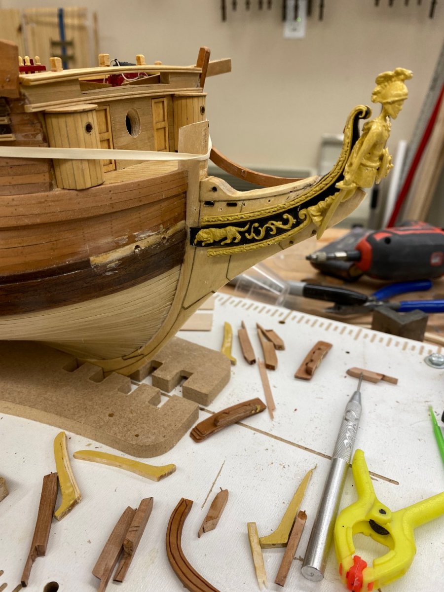
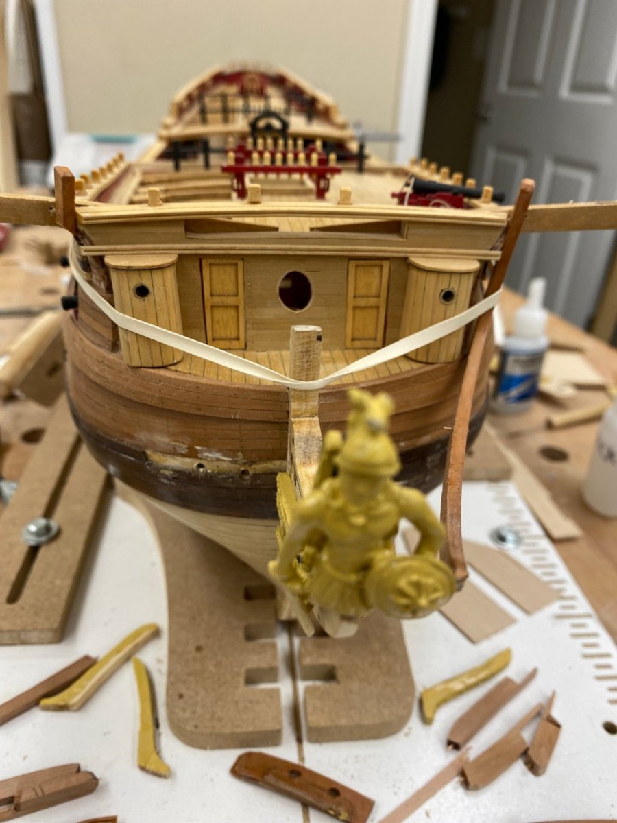
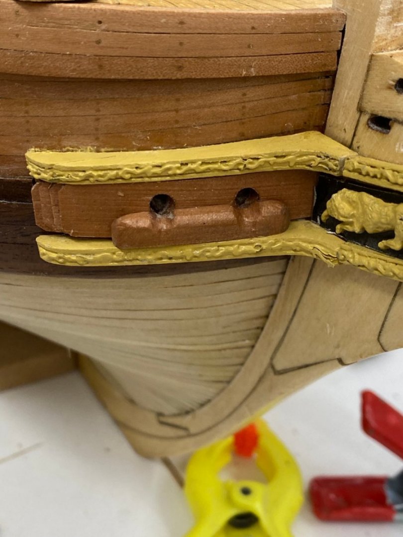
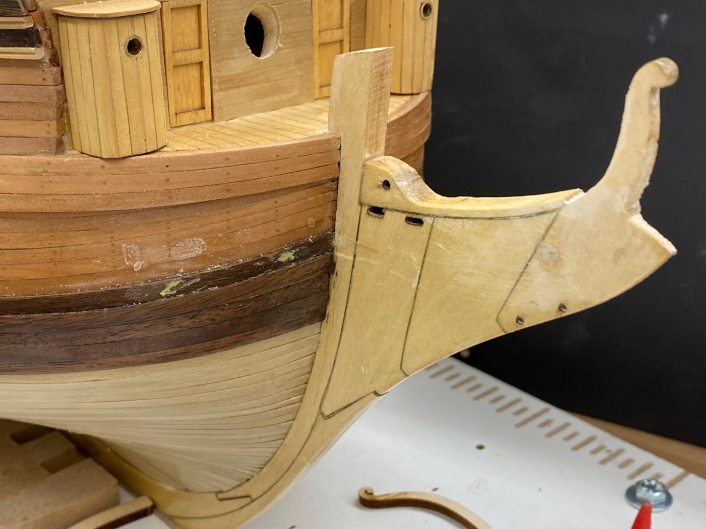
I have been so focused on the head timbers that I did not notice that for some reason (probably tension from the head rails which were probably a bit too long as they were installed) the stem came detached from the hull. You can see the gap below: While I considered just ignoring this it soon became obvious (at least to me) that this had to be fixed. So I cut the head timbers at the bow (but still managed to break one near the junction with the hull). Here is the starboard side with the upper and lower cheeks and hawse holes removed. The stub of the starboard head rail is at the top left of the picture. I wondered where the best place to cut the stem so it could be removed and decided to cut it at the scarf joint. I used the finest saw blade I had (54 tpi) and when I got through most of it the remainder broke off but it forms a nice junction at the bottom so if I apply aft pressure at the top the bottom will not pull out. Here is the stem after removal. I cleaned up the stem and beveled the edges a little so it would fit smoothly (more or less) back onto the hull. I will have to touch up with WoP when this repair effort is finished. One thing I noticed looking at the stem is that there was no glue residue on the top half of the removed piece. Guess I will have to review my gluing technique before the next build. So I got my supply of rubber bands out and found one the right size to keep the stem in place and applied a liberal amount of Weldbond glue to the stem and put it in place.. Once this sets up it is on to replacing the pieces removed. I will also have to refab the starboard head rail as I broke it in the process. Yet more fun.


- 370 replies
-
- 1
-
-
- Model Shipways
- Confederacy
- (and 1 more)
-
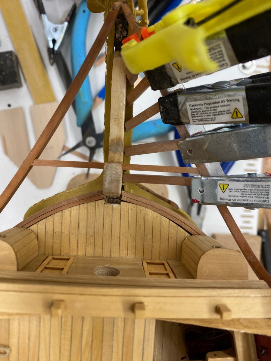
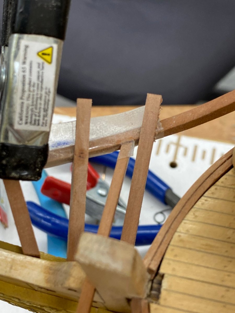
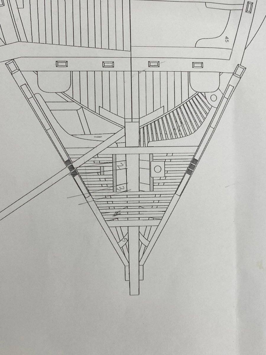
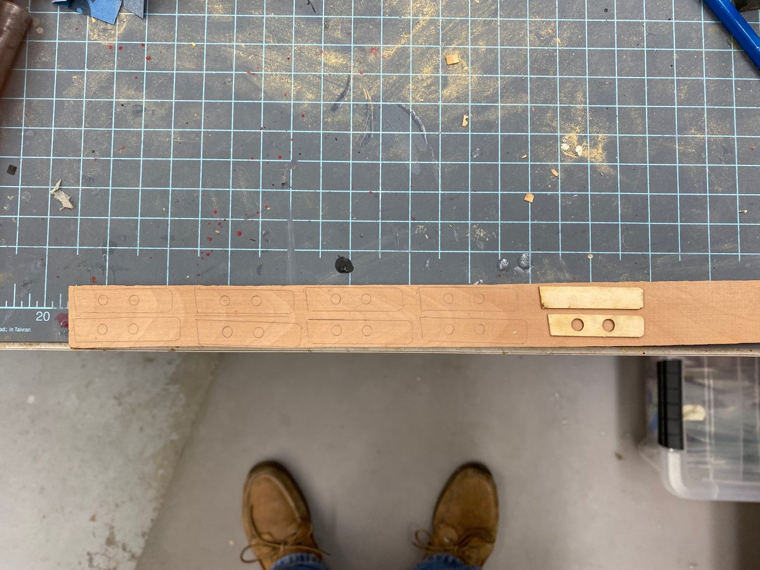
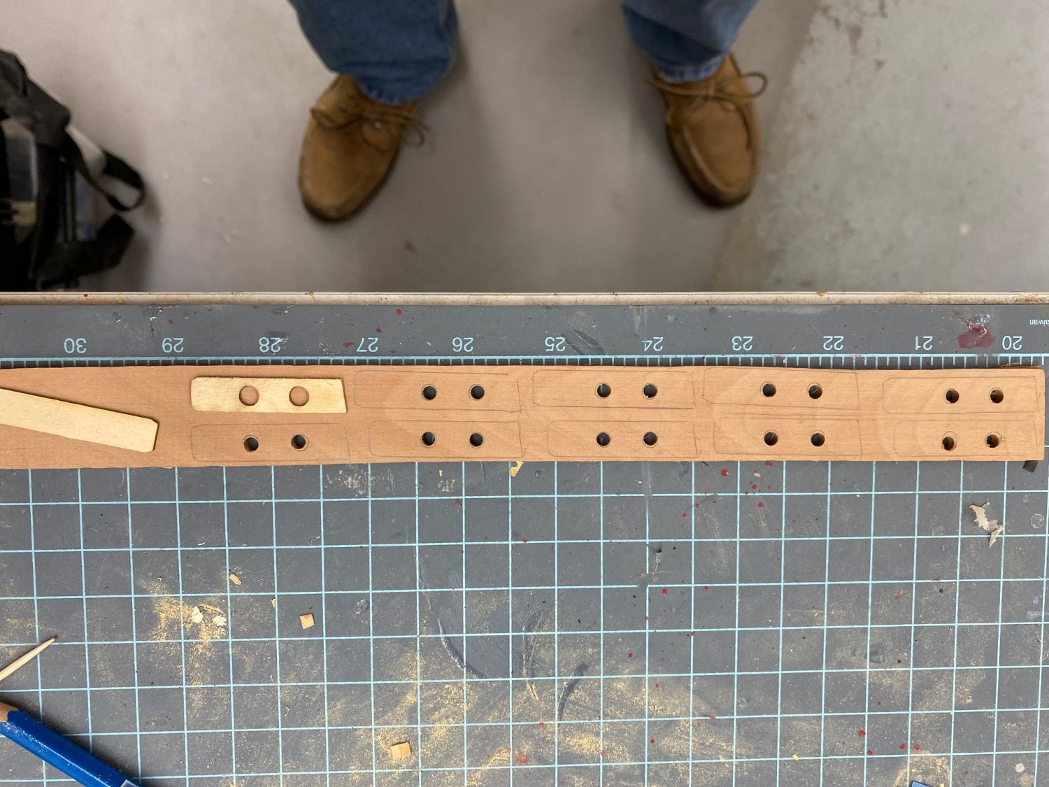
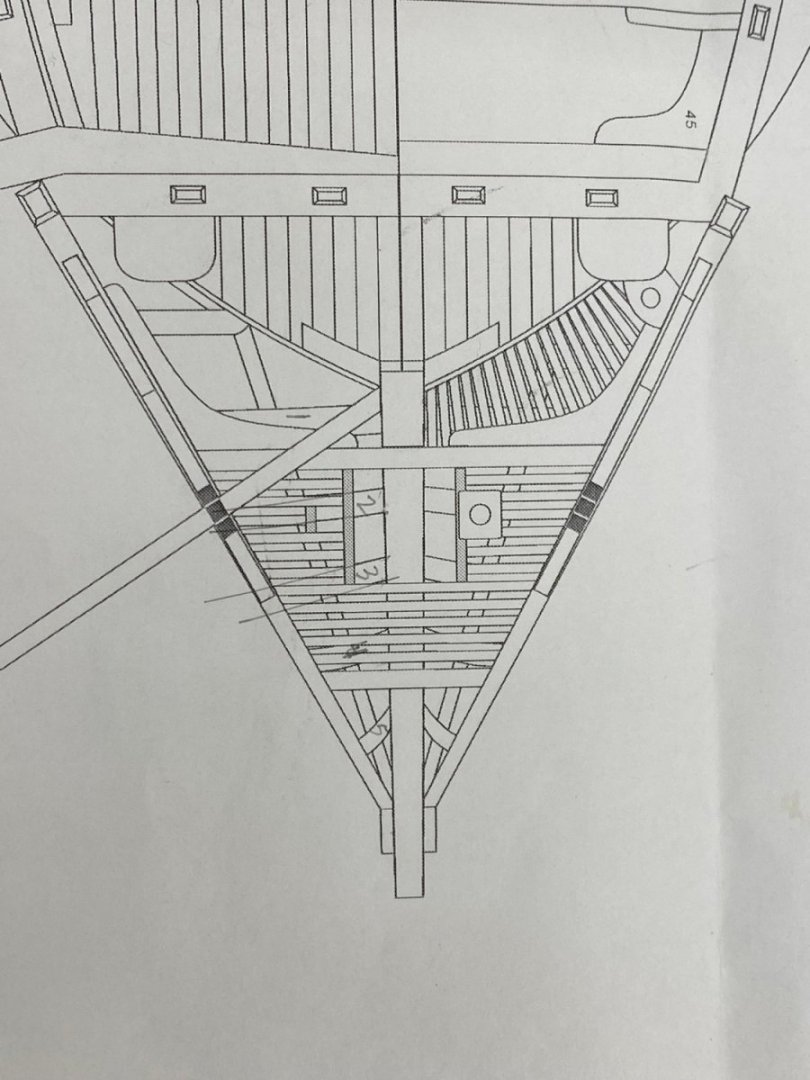
I indicated in the instructions and previous comments from other builders I can confirm that the head timbers are a real pain. I started by gluing the template from the plans onto the specified 1/8" X 1/4" pieces (Swiss Pear). As some fiddling around I figured out that the templated pieces should have to paper facing aft. Then I looked at Sheet 1 of the plans where there is an overhead view of the bow but there are so many lines on top of the head timbers that it is hard to get accurate measurements. Here is that part of the plans. I tried to number the timbers and approximate where they would lie on the stem and what angle they take to the stem and the head rail. The templated pieces were pretty close but it was hard to hold. So I made new pieces but retained a "handle" by extending the top of the piece well past the head rail but as thin as I could make while retaining enough material to support the multiple handlings that are part and parcel with this part of the build. To locate the stem end I again used the ,025" phosphor-bronze wire in the end of the head timber and then clamped the handle to the head rail. Here are the starboard side timbers clamped into position. Admittedly hard to see the forward most one becasue of the clamp and it is nearly vertical anyway. Here you can see the handles on timbers 1 and 2 (my numbering on the plan). That is double-sided tape on the head rail as an added feature to keep the head timber end in place. I originally thought this would be enough but it turned out the tape isn't that sticky so I had to use the clamps too. I took the model off of the building board, laid it (carefully) into a foam carrier (actually two of them end to end) and used the template for the middle rail to mark the head timbers. The two marks are my attempt to try and "guess" where the edges of the "V" notch that is supposed to hold the middle rail should be. I am guessing I am going to be putting the head timbers in and out of position several times until I get the notches correct. I am tempted to complete this side before moving to the port side but think it might be smarter to use these head pieces to make "draft" pieces for the port side before they are permanently installed.

- 370 replies
-
- 3
-
-
- Model Shipways
- Confederacy
- (and 1 more)
-
I decided to try my hand at the head rails in Swiss Pear. In fact I fabbed one of the head rails in boxwood too short and could not find another 1/8" thick piece big enough to make another - sooo on to Swiss Pear (which I have a bunch of). Same process as with boxwood. I won't bore you with pictures until I get them mounted. To try and get the head rail and the beakhead deck at the same level at the stem i built a jig that I clamped to the stem. Because the top of the head rail is supposed to be at the same level as the beak head deck I cut 3/32" "notches into the jig so top of the head rail will be at this height. Here is a shot of the jig without the head rails. I measured a dozen times to try and make sure the jig was "square" with the ship centerline. Here is a shot from above with the two head rails in place. I decided that the joint at the top of the head rail needed more support than just glue so I added a .025 phosphor-bronze wire to the joint. Hopefully I can cover the hole with the diamond shape if I can get the wire at least flush with the head rail. You can see the wires in the photo above at the top and bottom right corners. I did the same with the head beam junction with the head rails. You can see the wire in the photo below. So on to the head timbers. The instructions include picture of the head timbers from two sides, too bad the plans only show one dimension. If I had both views in the plans I might be tempted to just glue them onto a billet (of Swiss Pear in this case) and use that as the starting point. I will at least use what the plans provide and hope for the best.


- 370 replies
-
- 1
-
-
- Model Shipways
- Confederacy
- (and 1 more)
-
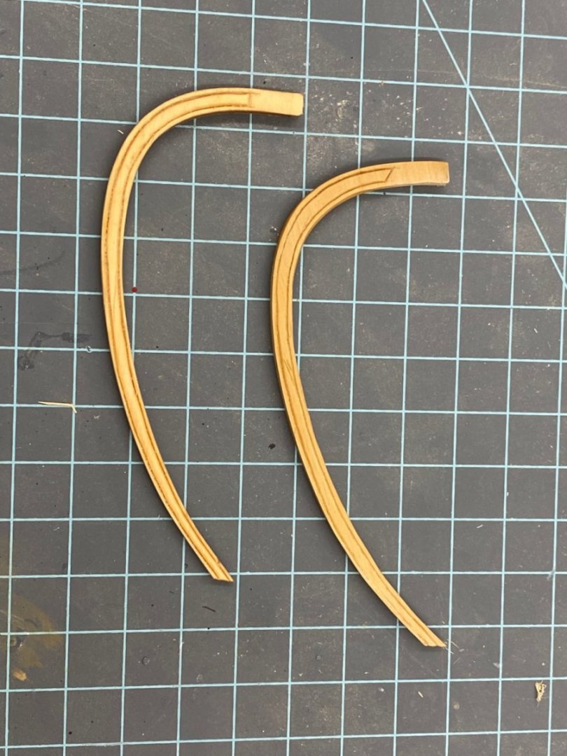
After creating the two head rails using the kit provided laser cut pieces I decided to experiment with recreating the head rails in boxwood. It was not too hard, using a disk sander and the Dremel sanding attachment I manged to get what I think is pretty close to the required shape. Putting the molded profile in the harder boxwood caused some changes to the procedure in the instructions. Instead of a single #11 blade cut and the widening with the awl/toothpick, I made two parallel #11 blade cuts on each side of the head rail. The two cuts each side are very close together, less than a 64th", actually as close as I could manage. Then the very small slice is pulled out by tweezers or pushed out when the awl is used. It seems to clean up better with small pieces of sandpaper than the basswood does. Here are the basswood and boxwood pieces shortly after a paint thinner rub down. The boxwood is on the right. Tomorrow more Old English gel stain (fruitwood) arrives and I will stain the basswood and WoP both to see which looks better on the model.
- 370 replies
-
- 1
-
-
- Model Shipways
- Confederacy
- (and 1 more)
-
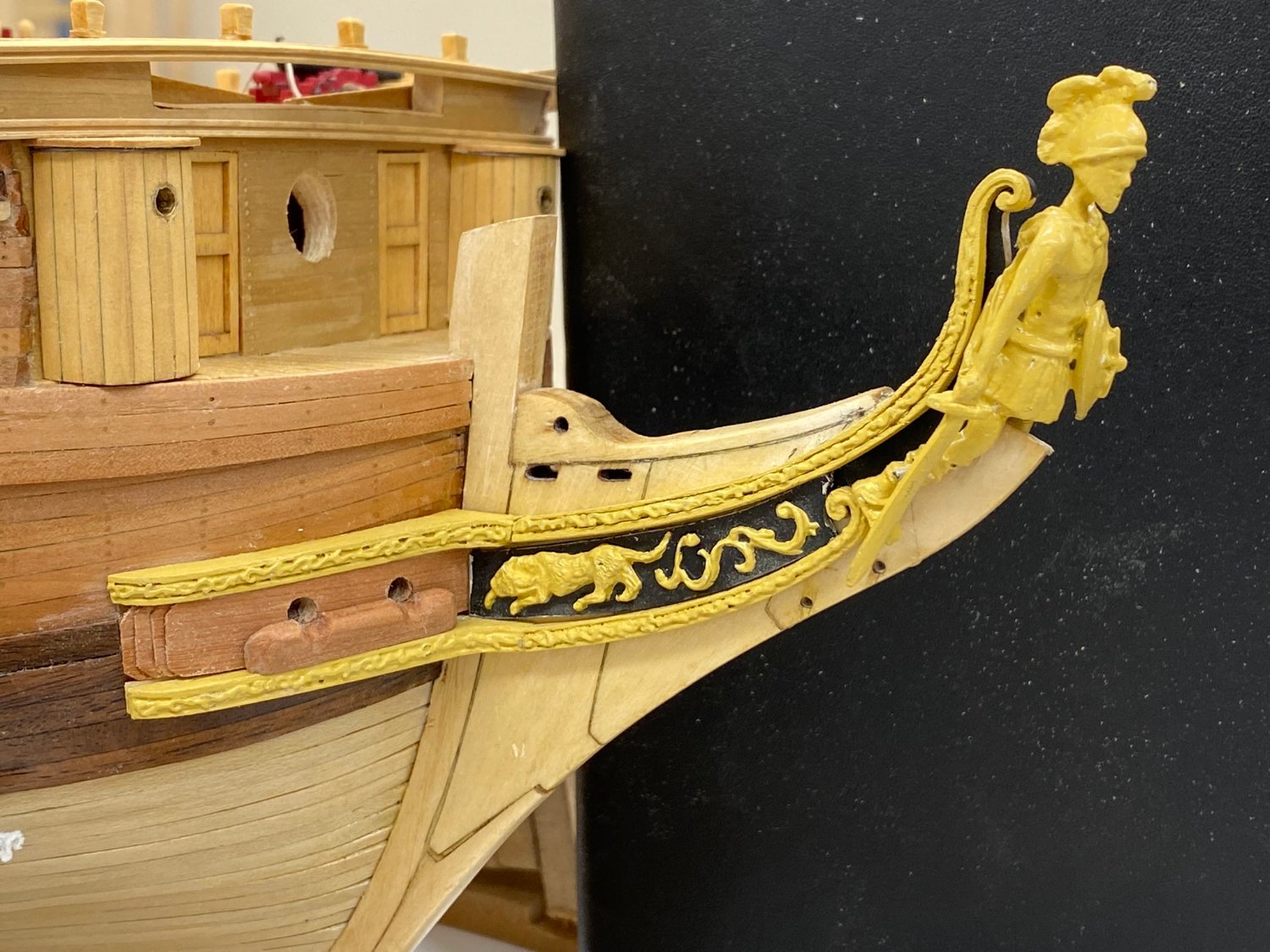
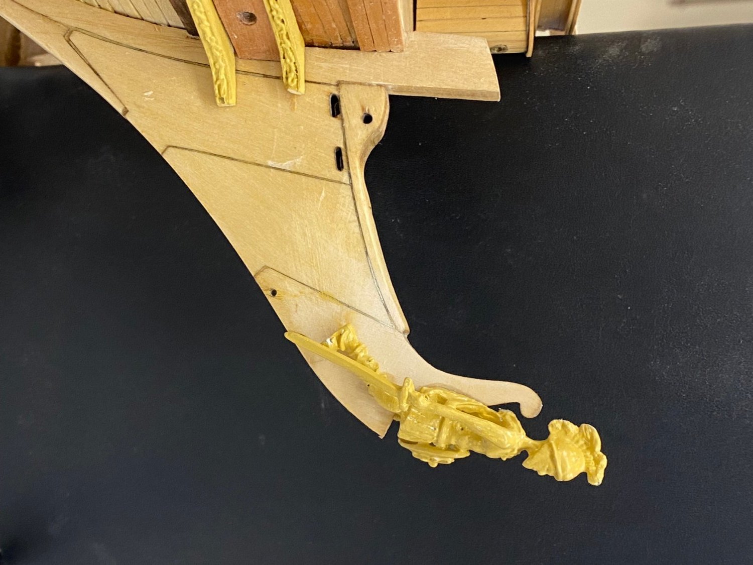
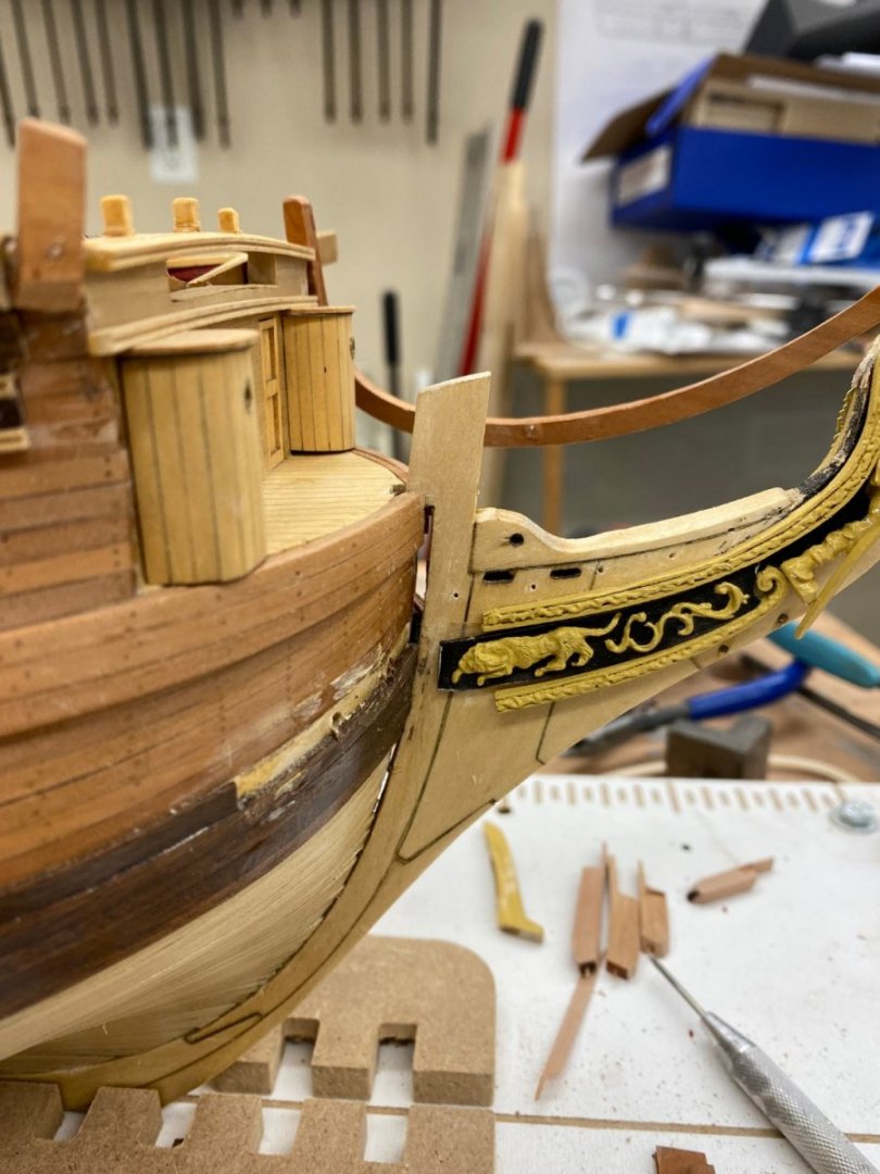
I completed the port side in a similar fashion to the starboard. I clamped two pieces that I cut from a single billet to both sides of the stem with the starboard one resting on top of the upper cheek to make sure I got the upper cheeks in a similar position on both sides. 21887F75-7309-45ED-B777-98925B2EC1A5.heic Here is what the port side looks like as I proceed to getting the head rails fabricated and installed. Some touch up required on the figurehead I see. and I did not get the lower cheek as close to the trailboard as I might have liked.
- 370 replies
-
- 2
-
-
- Model Shipways
- Confederacy
- (and 1 more)
-
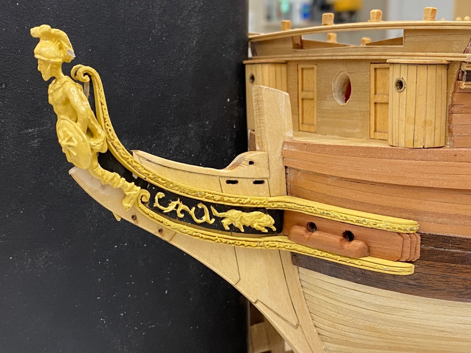
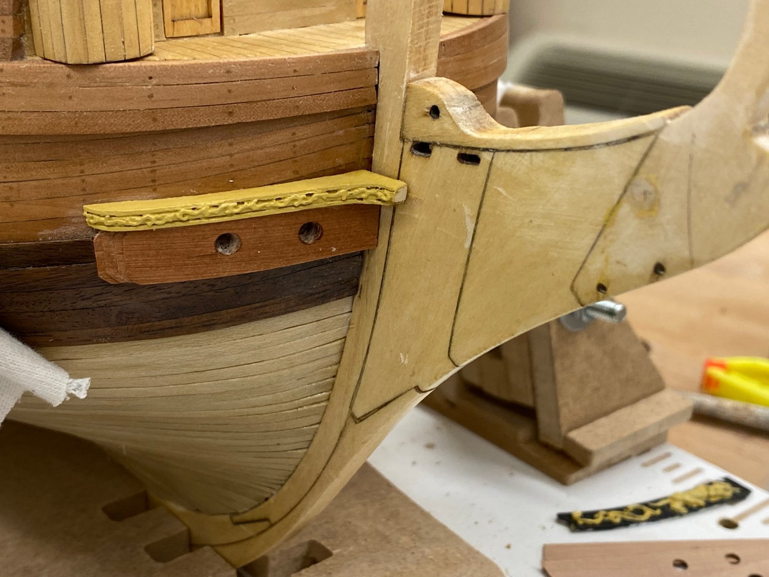
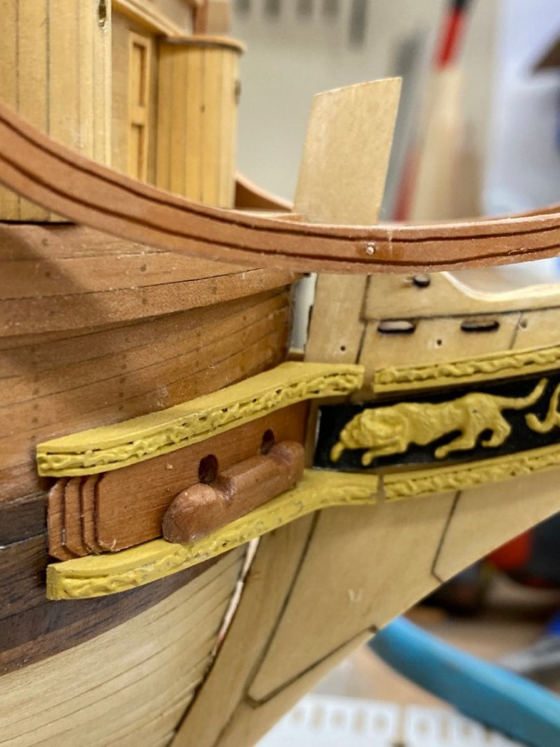
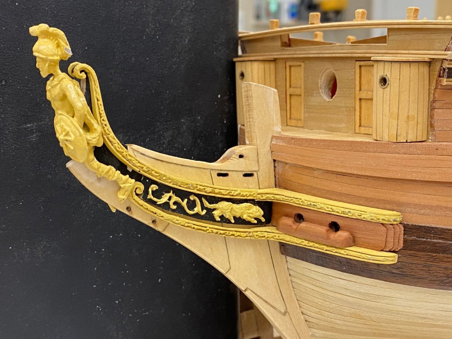
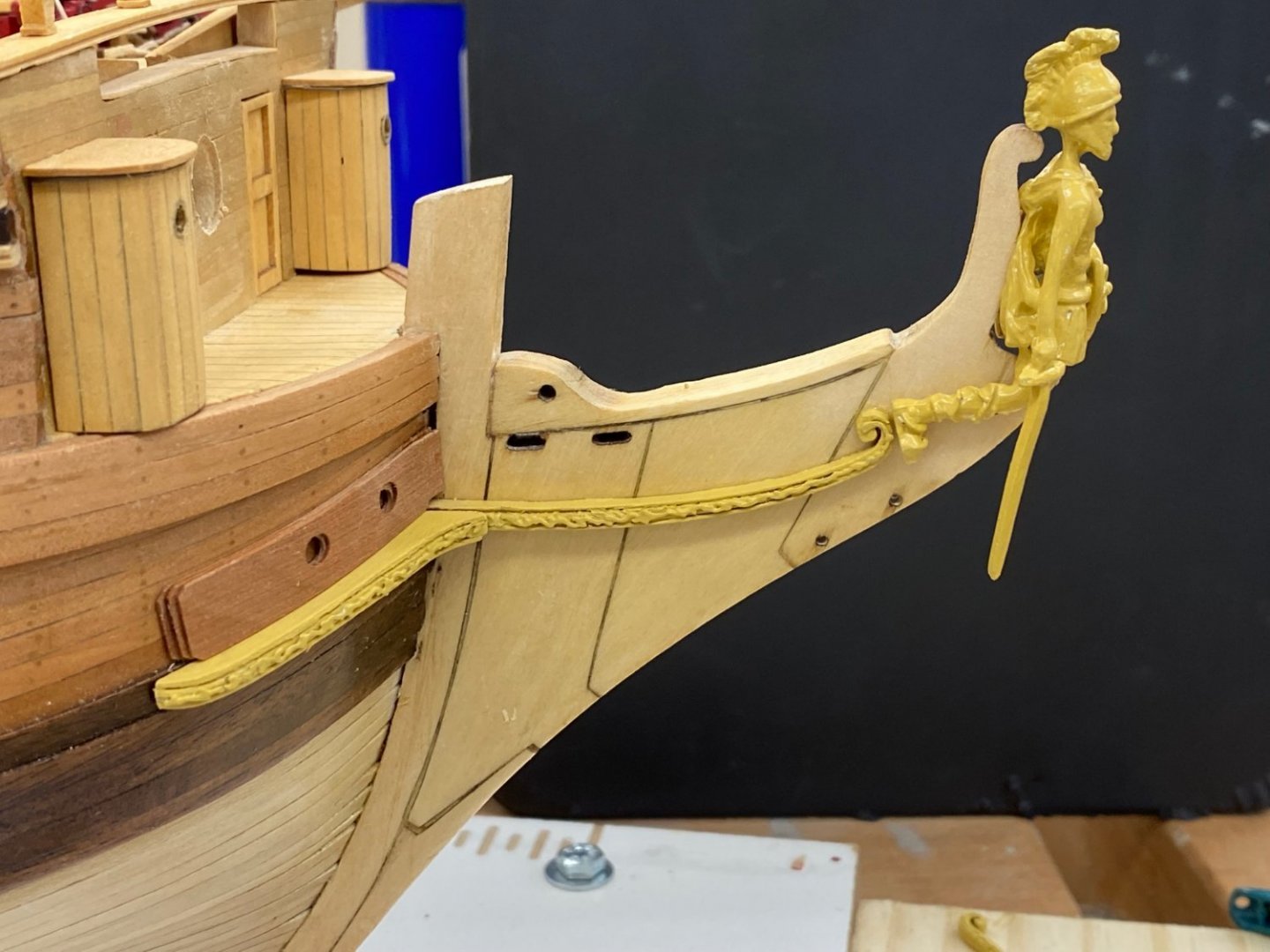
So the starboard side cheeks are complete. I think most things are at least close to where they are supposed to be; at least on the stem. The trailboard came out better than I expected. The instructions imply painting the black first and then the "wood" (aka yellow). I tried that and when that did not look so good I painted the yellow first. It seems (to me) easier to "flow" the black around the raised yellow parts. Besides, black covers yellow better than yellow does black. On to the port side. And while I was waiting for paint to dry I fianlly added the molding on the beakhead bulkhead. Not perfect but you have to look really close to notice that the lower starboard piece is a little higher than the port.

- 370 replies
-
- 2
-
-
- Model Shipways
- Confederacy
- (and 1 more)
-
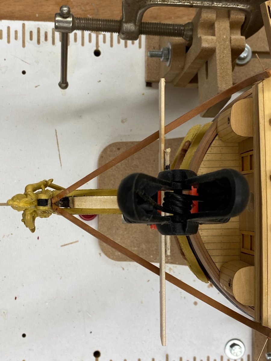
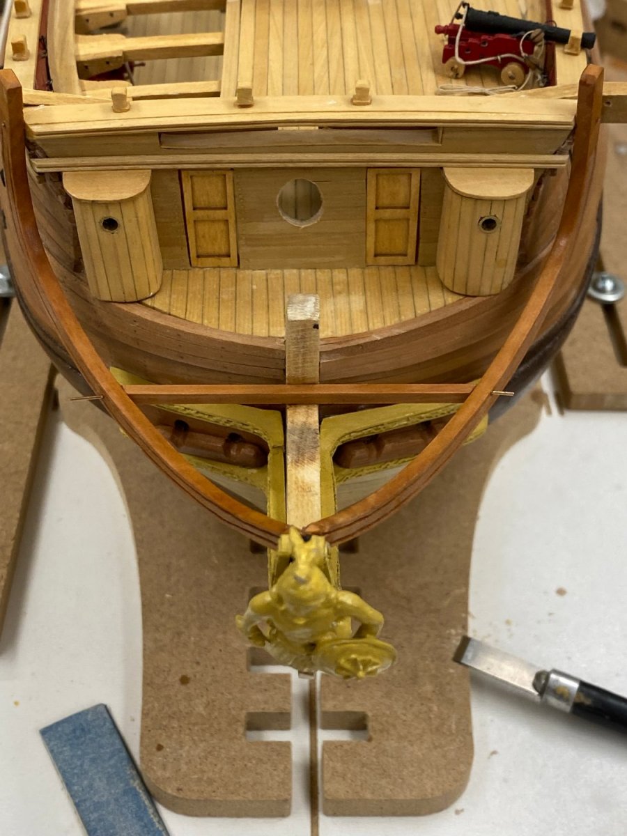
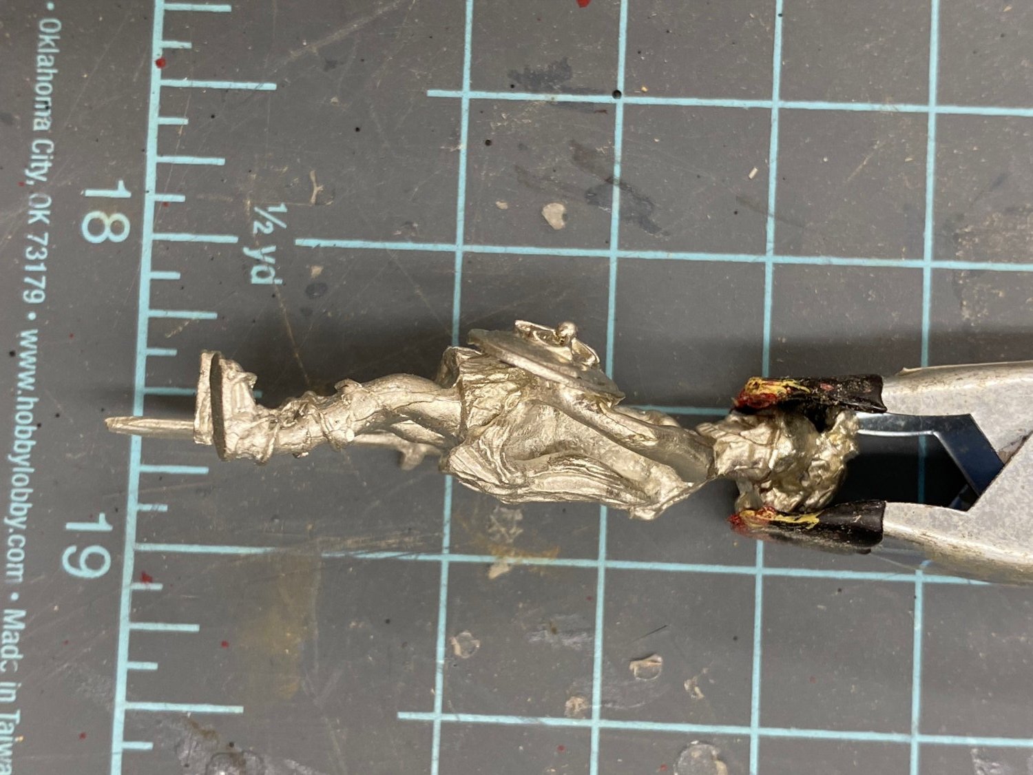
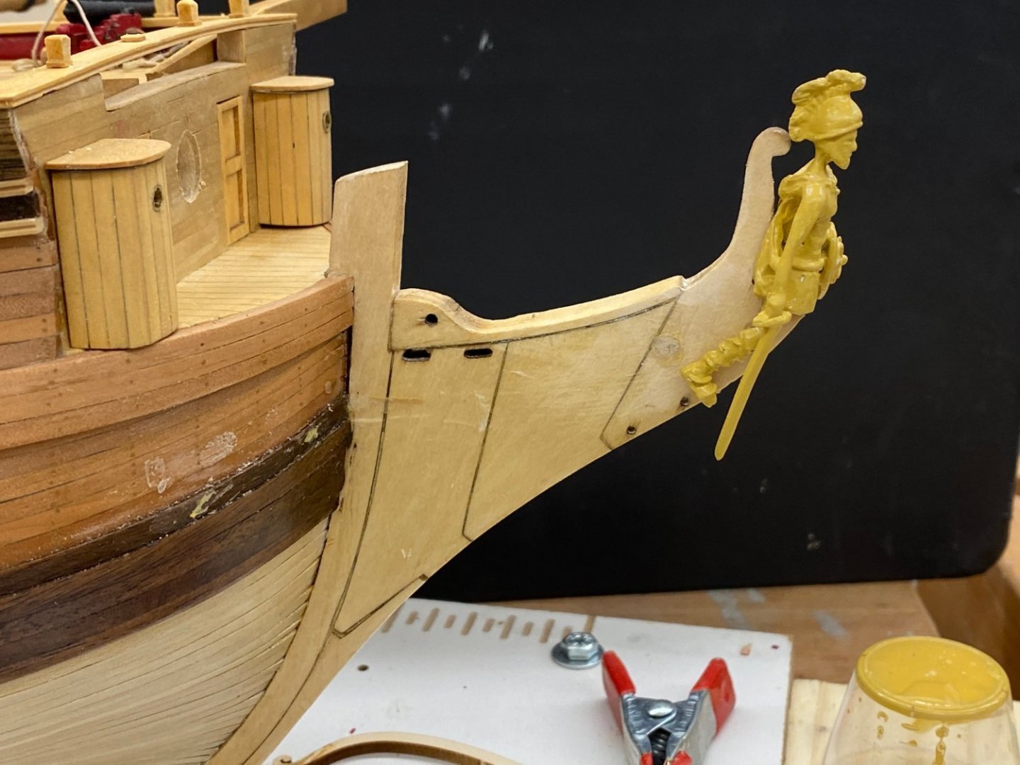
Since it appears that the location of the figurehead's foot (feet) is an important feature of where the lower cheeks go I decided to glue the figure head on now rather than later. I probably overdid things but I used 5 minute epoxy as the glue. I am not sure what else would bond Britannia metal (I assume that is what the figurehead is made of) man basswood. I guess CA would work but I would not want this falling off anytime soon. Sorry - another example of the web site rotating pictures seemingly at random.

- 370 replies
-
- 2
-
-
- Model Shipways
- Confederacy
- (and 1 more)
-
Thanks guys, I looked ahead at the instructions for the head timbers and am definitely not looking forward to having to build twelve really tiny, curved, end notched pieces from what is provided in the kit.
-
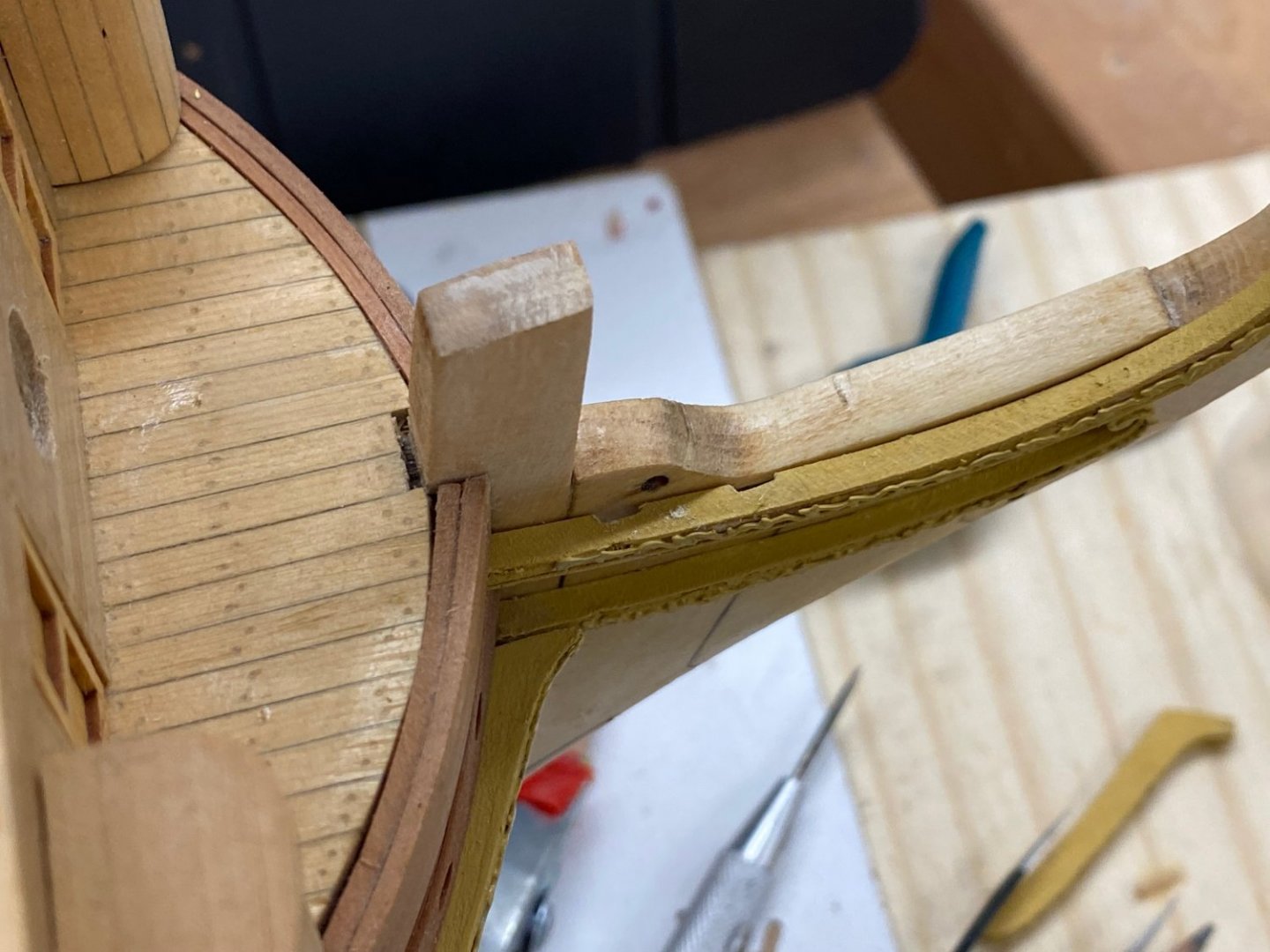
Given my issue with spacing of the upper and lower cheeks and that it is the upper cheek that determines how much space is left on the stem I decided to install the upper cheek first. So here is the aft part of the upper cheek and the hawse holes on the starboard side. I removed the black strake as far as the cheek (and hawse holes) and put a coat of WoP on the hawse holes. Now I KNOW where the lower cheek goes and hopefully the trailboard will fit too (or I modify it so it does).

- 370 replies
-
- 3
-
-
- Model Shipways
- Confederacy
- (and 1 more)
-
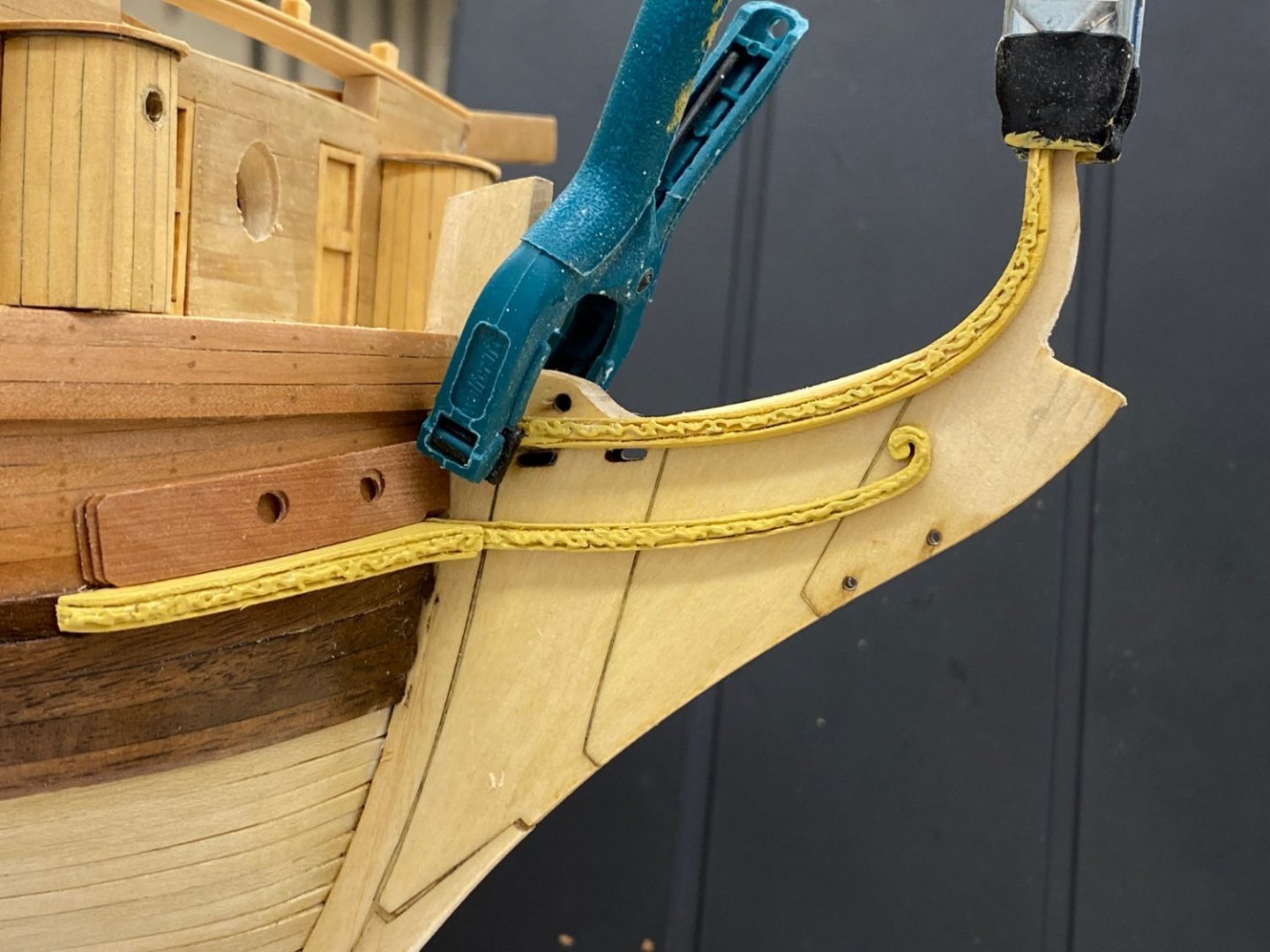
Back to the drawing board on the cheeks. If I do not "fix" this problem now there will nothing for the head timbers to rest on and that is just the first real issue I see. So I pulled off the cheeks and hawse holes and will fabricate new pieces that will land on the top strake of the wales instead of the black strake. That is the only way I see to get the cheeks where they need to be in relation to the stem pieces which have been in place since "the beginning". I also see now that the figurehead's legs should not be bent (at least as much as they were) and I have done a bit more sanding on the stem to get the figurehead in the correct (more or less) place. More to follow!
- 370 replies
-
- 1
-
-
- Model Shipways
- Confederacy
- (and 1 more)
-
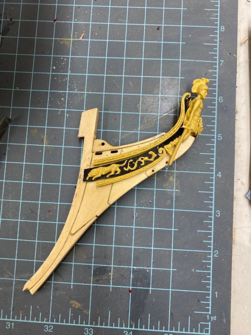
On to the cheeks. I had to bend the legs of the figurehead casting a good deal to get them to match the drawing. Here is what it looks like "out of the box". You will see the finished figurehead below. Putting the molding along the edges of the cheeks is pretty tedious and it seems (to me at least) that the etched material glued on top of the cheeks makes the molded edge a bit less noticeable it is still worth the effort (IMHO). The real problem I had was in thinning out the forward pieces to 1/16" - I broke two of the four provided so I have no more "spares". I finally figured out to put the edge on the molding first, then remove the char and only when all that is done thin the piece. Here are the lower cheeks and the hawse holes dry fit. I did not follow the instructions and put the after piece on first. I put the forward (curved) piece on first and then trimmed the after piece to blend into the forward piece. This makes the seam run fore/aft rather than athwartships but mine is way more noticeable than the one pictured in the instructions. My hawse hole pieces are a little short (should end at the end of the cheeks piece but I think this is "close enough". Here are the lower cheeks (starboard side) installed with the figurehead on his perch but not yet glued down. With this done I dry fit upper, forward cheeks piece to see how much it had to be trimmed. And "up jumped the devil". According to the plans sheet one (the only place this is shown) the holes for the gammoning are supposed to be above the upper cheeks not below as they clearly are on my model. I am not sure how this happened but it pretty clearly is not something I am able to "fix" at this point. So, assuming that I will eventually install the gammoning for the bowsprit I filed two slots into the upper cheeks piece so the gammoning can go behind the upper cheeks rather than over them. I wait with bated breath to see what other 'issues" this apparent flaw in my construction technique will rear their ugly heads as I proceed with the head rails and other fun stuff yet to come.

- 370 replies
-
- 2
-
-
- Model Shipways
- Confederacy
- (and 1 more)
-
When I got to the hawse holes I recognized that if I want to maintain the Swiss pear exterior planking I was going to have to replicate the kit provided hawse holes in Swiss Pear. The instructions allude to simulating 1/64th" planking in the detail at the aft edges. I thought I could try and make the 1/64" layers of the hawse holes a reality. I had a length of Swiss pear that was a bit more than 1/16" thick so I laid out a set of eight hawse hole layers using the kit provided pieces as templates and indicated where the holes would be on all eight pieces. I then drilled out the hofles using a drill bit a bit smaller than the holes in the template. You have to bore them into the hull anyway so there will be opportunity to get them to "correct" size. Then I took the Swiss Pear to the thickness sander and started thinning it down. Luckily I remembered to only sand the side without the markings. I got the Swiss Pear down to about .02" (1/64th is .015") and stopped there as I it was beginning to get hard to push the wood through the sander, it was pretty flexible. So I stopped there. In recognition of that the kit provided items are ~ .0625" thick (two 1/32" thick pieces) I decide to stop at three .020" thick layers. So here are the two sets of hawse holes with the layered feature at the aft edges. Yea, the holes don't line up exactly but they have to be drilled into the hull anyway so I can clean that up then.


- 370 replies
-
- 5
-
-
- Model Shipways
- Confederacy
- (and 1 more)
-
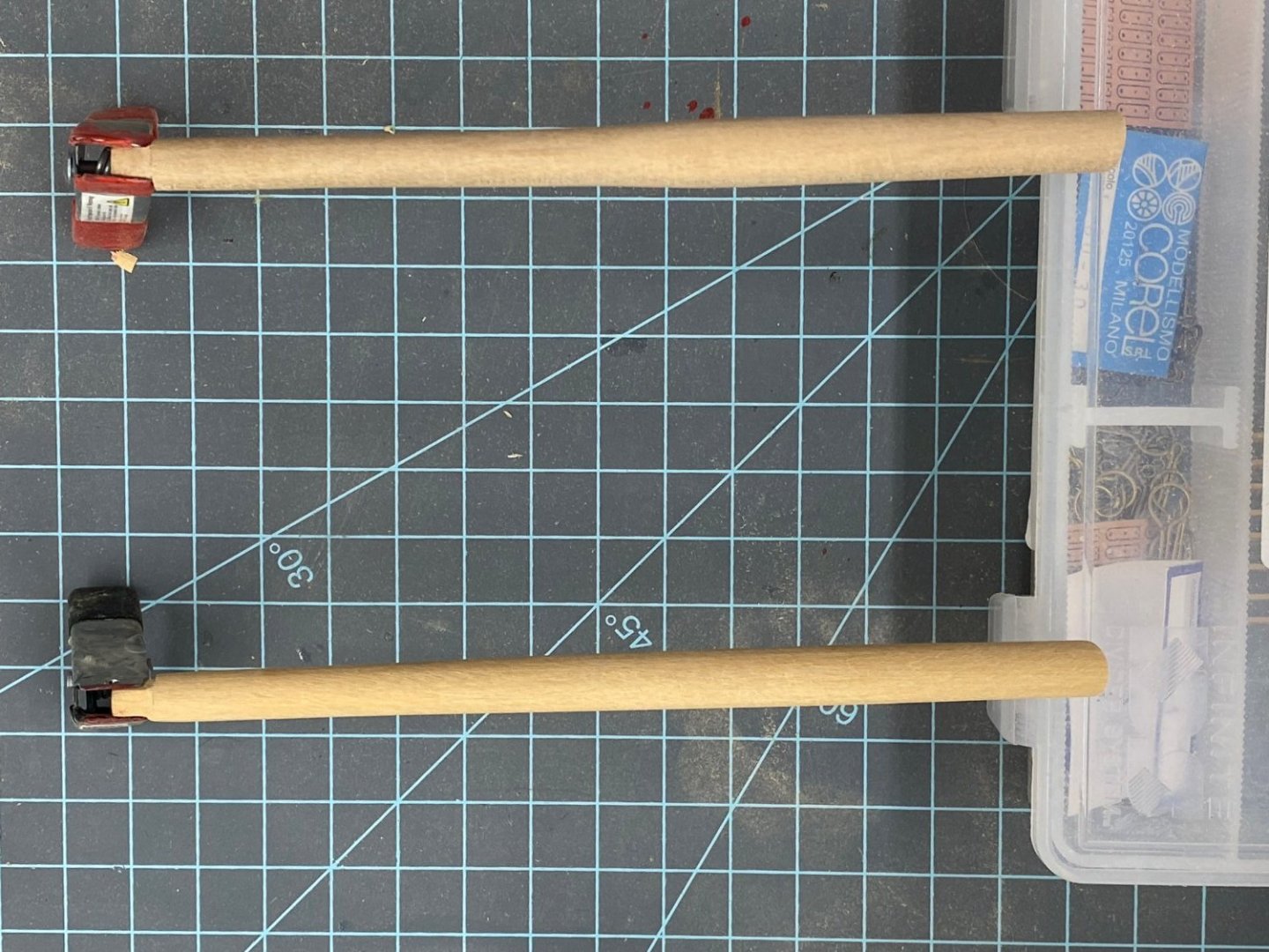
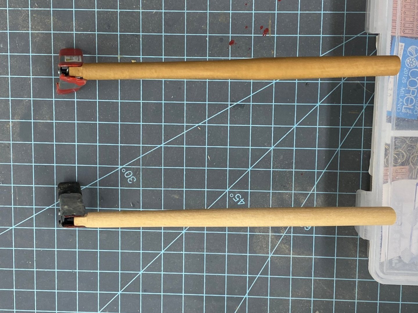
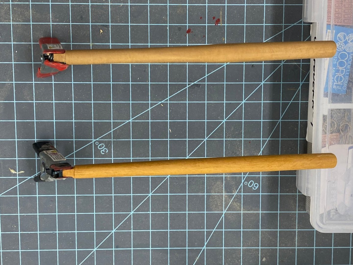
With the roundhouses (for which I used boxwood for the planks and top instead of the kit provided materials) in place (not yet glued) I started to wonder about the bowsprit. I used the kit provided dowel but I don't know what material that is made from. So I got out the "big" table saw and cut into one of the big billets of boxwood I got from the Rare Wood folks a couple of years ago (i.e. before COVID) and cut some pieces which I eventually got down to a 1/2" X 1/2" X 24" piece. If I decide to go this way that should be enough material for the bowsprit and the mast stubs. After using sanding sticks to make the billet octagonal I used my big drill press to get it circular (more or less) and then tapered to match the one I did from the kit materiel. Here are the two after 220 sanding but no finish (boxwood on the bottom - black clamp). For this kit I used Old masters Gel Stain in Fruitwood to try and get the basswood to come close to the boxwood color so I used that here as well. Here are the two bowsprits with only kit one stained. And finally here is the boxwood one with a coat of Wipe-on-Poly. I will get a coat of WoP on the kit one before decided which one to use but I ned to let the stain dry first.
- 370 replies
-
- 4
-
-
- Model Shipways
- Confederacy
- (and 1 more)
-
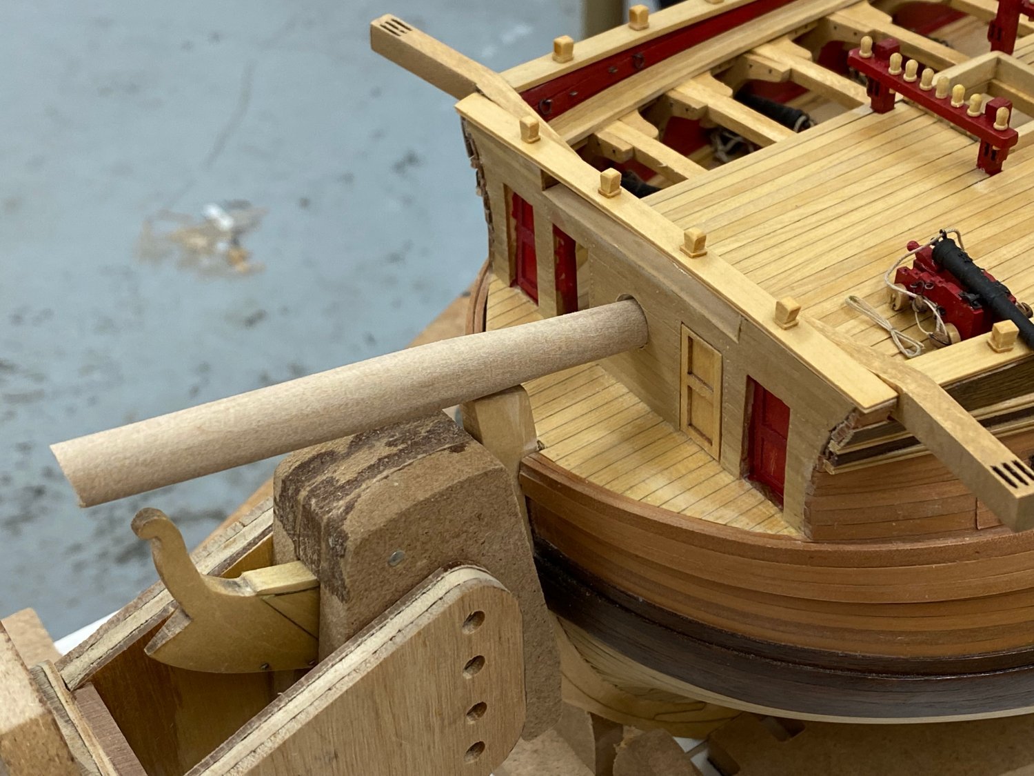
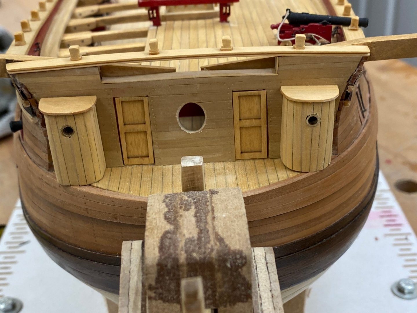
Next step is the bowsprit (while the roundhouses are drying) Interesting note is the the bowsprit starts as a 7/16 dowel, but the hole in the beakhead bulkhead is only 1/4" in diameter. The drawing (which the instructions says to get all the measurements from) shows the bowsprit as ~3/8" diameter where in comes through the bulkhead. Sooo, I got out the "big" rat tail file and opened up the hole in the beakhead bulkhead to 3/8". I chucked the 7/16" dowel in my big drill press (poor man's lathe) and tapered it down to about 5/16" at the bitts end and then made the tenon. Here is the unstained bowsprit dry fitted into the beakhead bulkhead and bowsprit bitts. It is admittedly hard to see the joint at the bowsprit bitts so trust me it fits.

- 370 replies
-
- 3
-
-
- Model Shipways
- Confederacy
- (and 1 more)
-
I finally got the fo'c'sle finished, at least as far as the instructions go at this point. The cat heads and timberheads were the last items and now they are installed and it is on to the head rails and other fun stuff at the bow.

- 370 replies
-
- 5
-
-
- Model Shipways
- Confederacy
- (and 1 more)
-
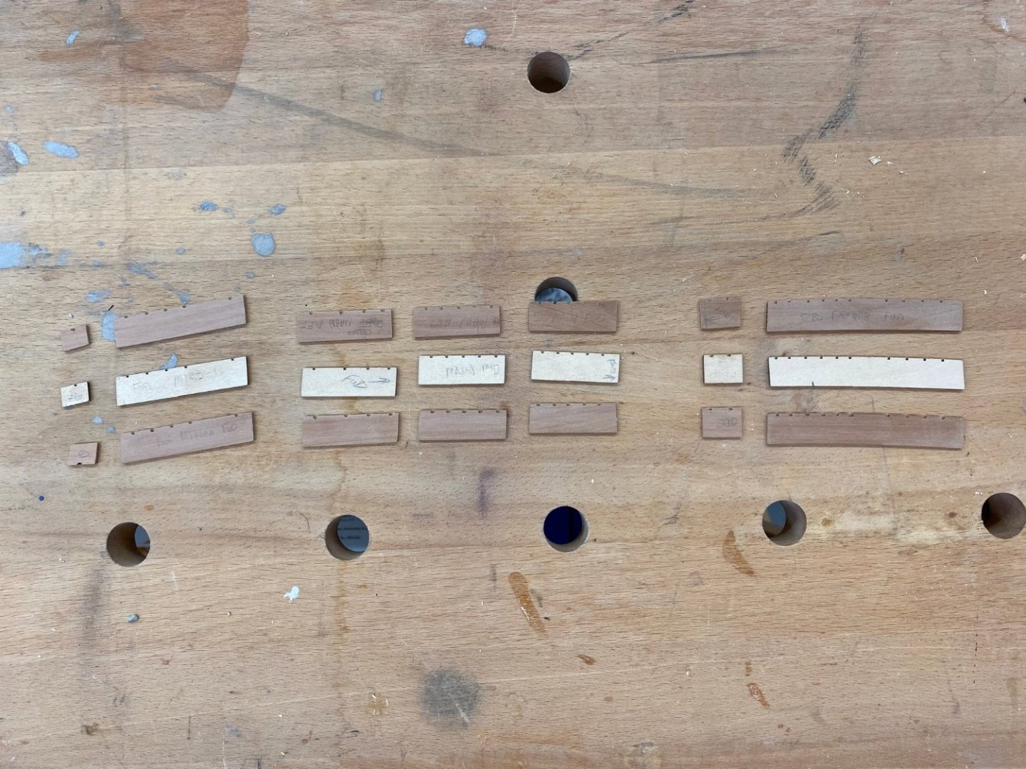
Since I planked the hull in Swiss Pear it occurred to me that I would probably need to fabricate channels from Swiss Pear to maintain a consistent appearance. While waiting for the cat heads Wipe-on-Poly to dry I cut and sanded replacement channels. Here are the replacements and one set of the ones from the kit. The marking were to help me make sure I had a port and starboard set . Although only yhe forward most channel has much curve to it. The rest are almost straight where they contact the hull.
- 370 replies
-
- 3
-
-
- Model Shipways
- Confederacy
- (and 1 more)
-
I completed all of the items on the fo'c'sle except for the timberheads on the main rail. I wanted to get the cat heads installed before adding them. Speaking of the timberheads my decision to use a boxwood main rail instead of the painted one in the instructions now reared its ugly head and I had to either make boxwood timberheads or try and use the basswood ones that came with the kit, stained (hopefully) to not look too bad on top of the boxwood rails. After several tries I managed to figure out a way to "manufacture" these timber heads. It requires making two cuts in suitable thickness materiel (boxwood) to form a trapezoid. The question was what angles to use. My first attempt used the 75 degree stops on my table saw miter gauge. Comparison with the kit provided items showed that to not be steep enough. I finally settled at about 80 degrees for the upper portion. Cutting a bunch of trapezoids and then cutting them off at about 4mm height turned out to be not that easy until I added an additional piece of wood on top of the part being cut to keep the very small pieces from flying all over as they were cut. I then had to sand the bevel on the top edges and remove any char from the saw. For the base I sanded a piece of boxwood of suitable width to just under 1/32" thick and glued the trapezoids to this to form the complete timberhead. After cutting them off the "base" and trimming them flush on the sides and even with the tops on the ends to form the finished timberhead. I gave them a coat of Wipe-on-Poly and they are sitting to the left of the fore pin rails awaiting installation on top of the main rail. Once I have the cat heads in place I will glue them down and that will finish the quarterdeck work (at least for now). Once the catheads are installed it is on to the headrails - looks like much fun indeed.
- 370 replies
-
- 3
-
-
- Model Shipways
- Confederacy
- (and 1 more)
-
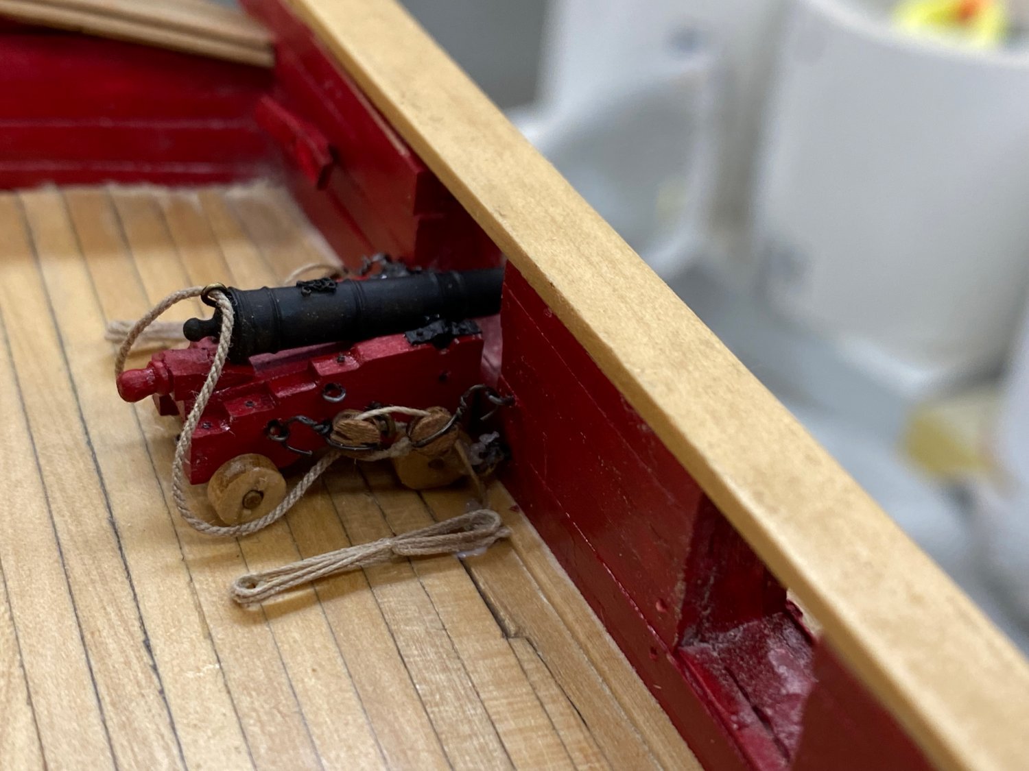
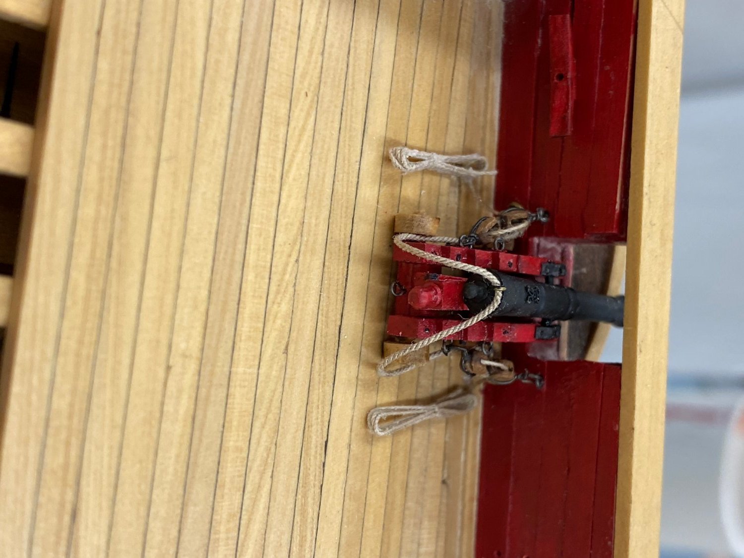
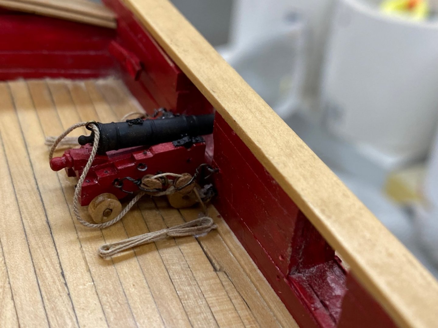
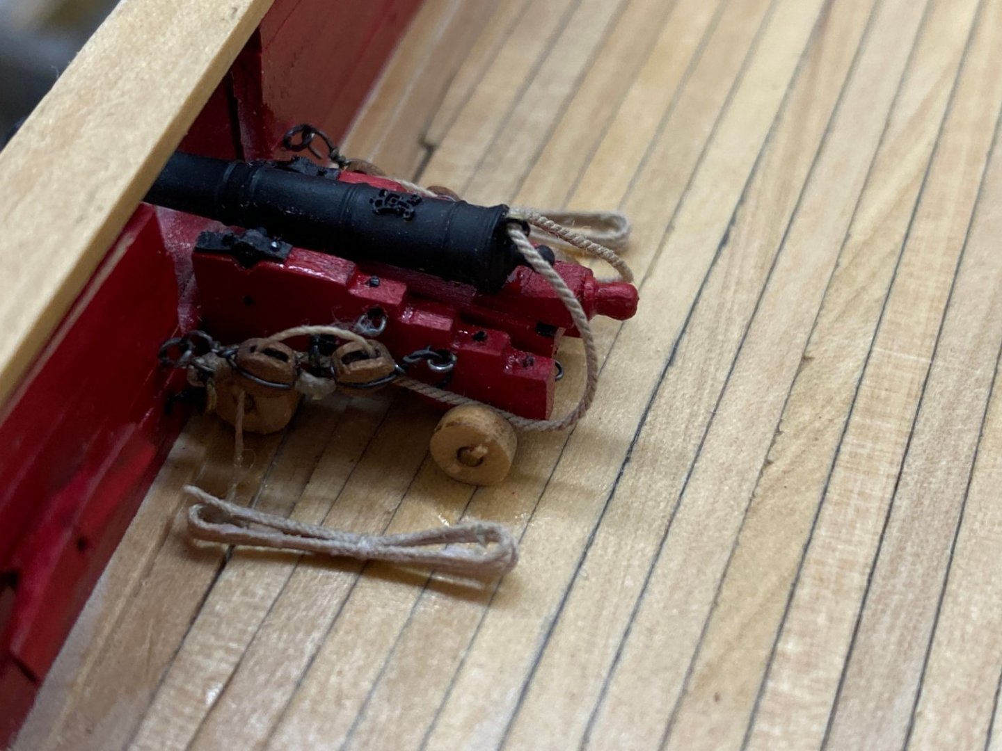
Given my tendency to get my elbows and other parts of my anatomy in places where they can do damage I decided to mount the quarterdeck (and fo'c'sle ) guns now rather than after adding the various pieces of delicate (ship's wheel for instance) equipment that goes more or less in the center of the deck. So it was back to making tackle and eyebolts again. Anyway, they are all finished now and I decided to get one gun completely mounted/furnished to make sure I had not forgotten something in the long period that has elapsed since I did this for the gun deck guns. Here is what the "test run" looks like. I have no idea why the site rotates some pictures and not others - I put this in the site in every orientation and it faithfully reproduces every one but the correct one!

- 370 replies
-
- 3
-
-
- Model Shipways
- Confederacy
- (and 1 more)
-
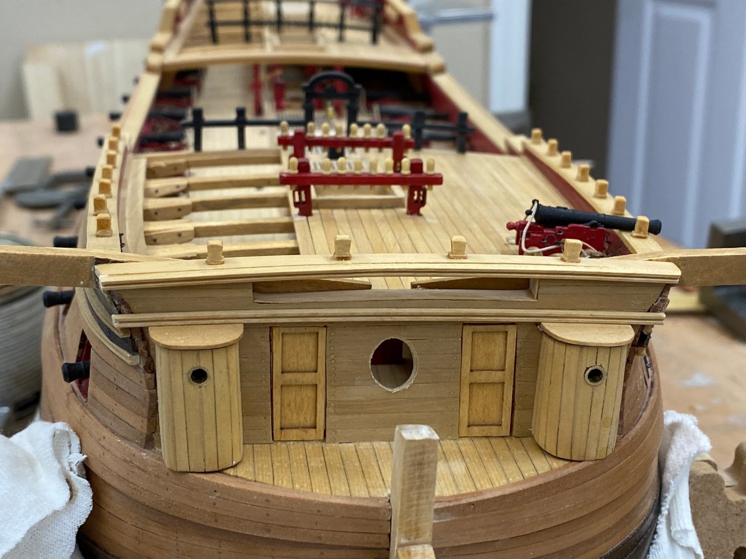
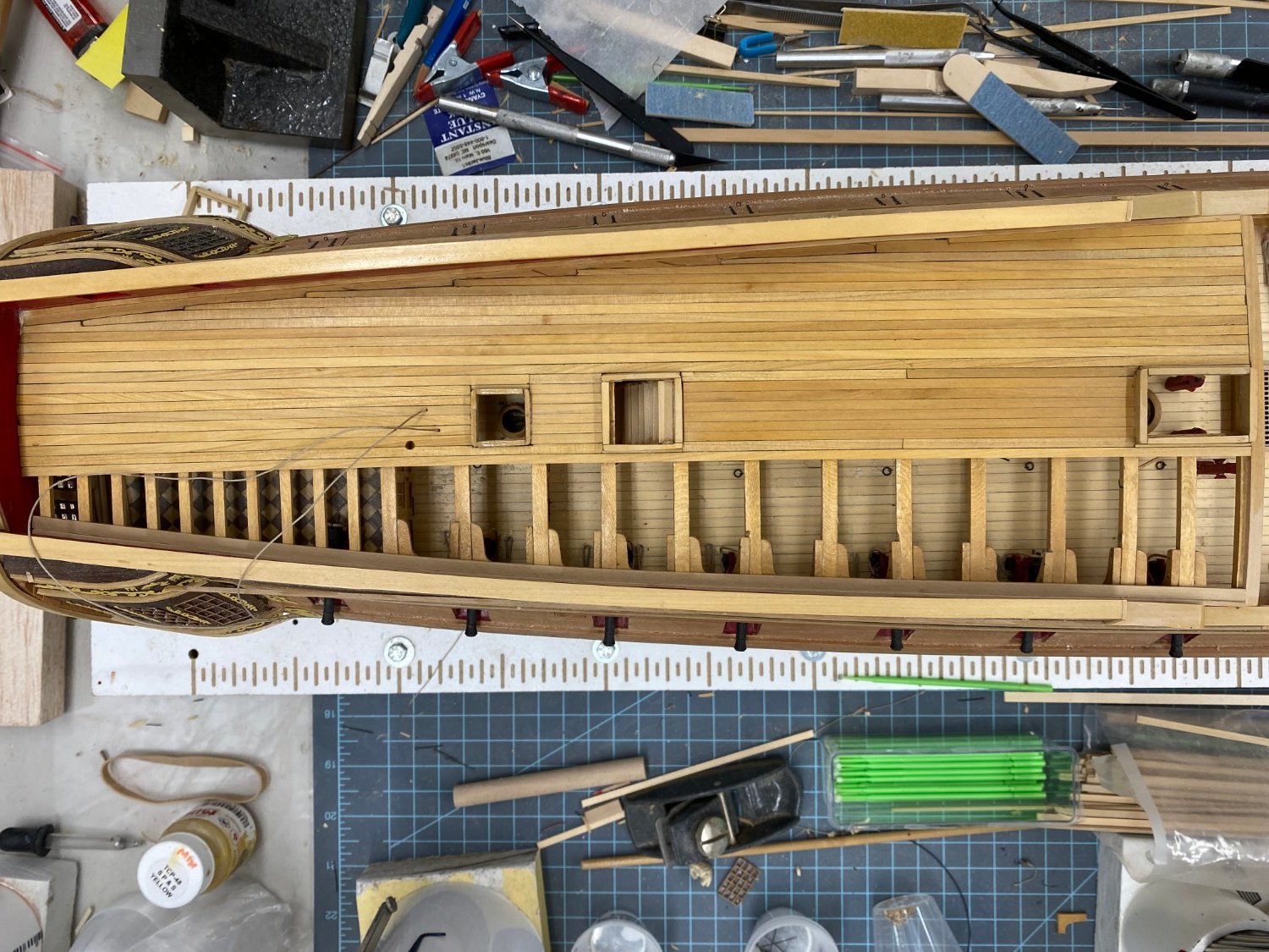
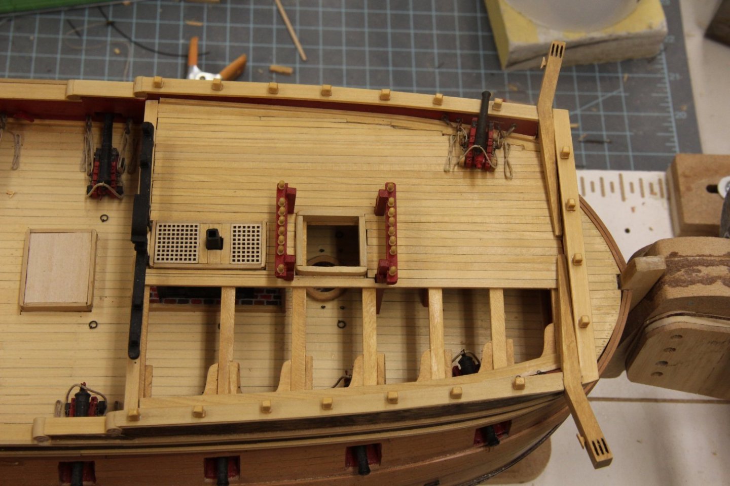
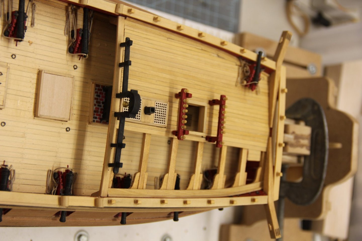
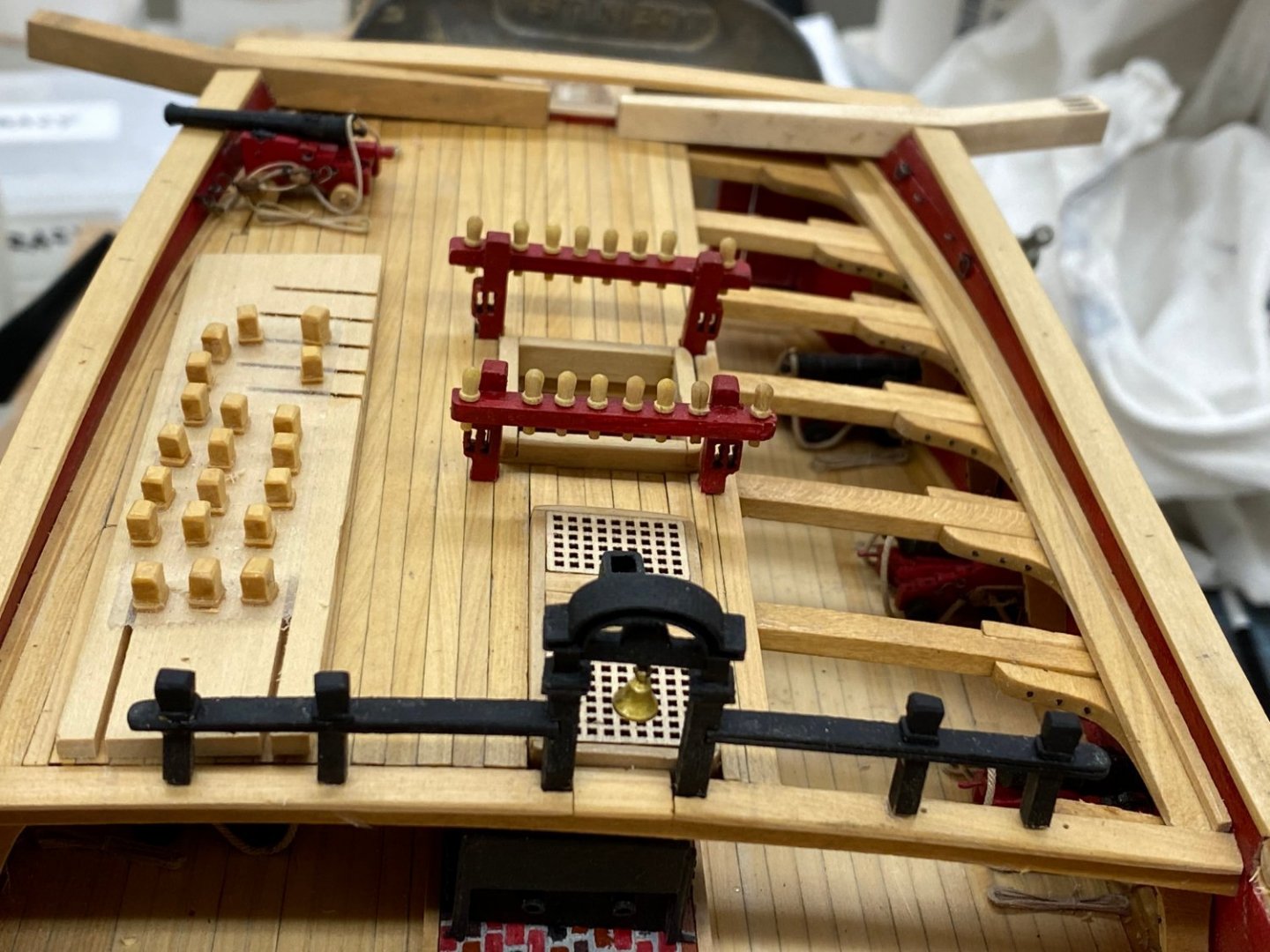
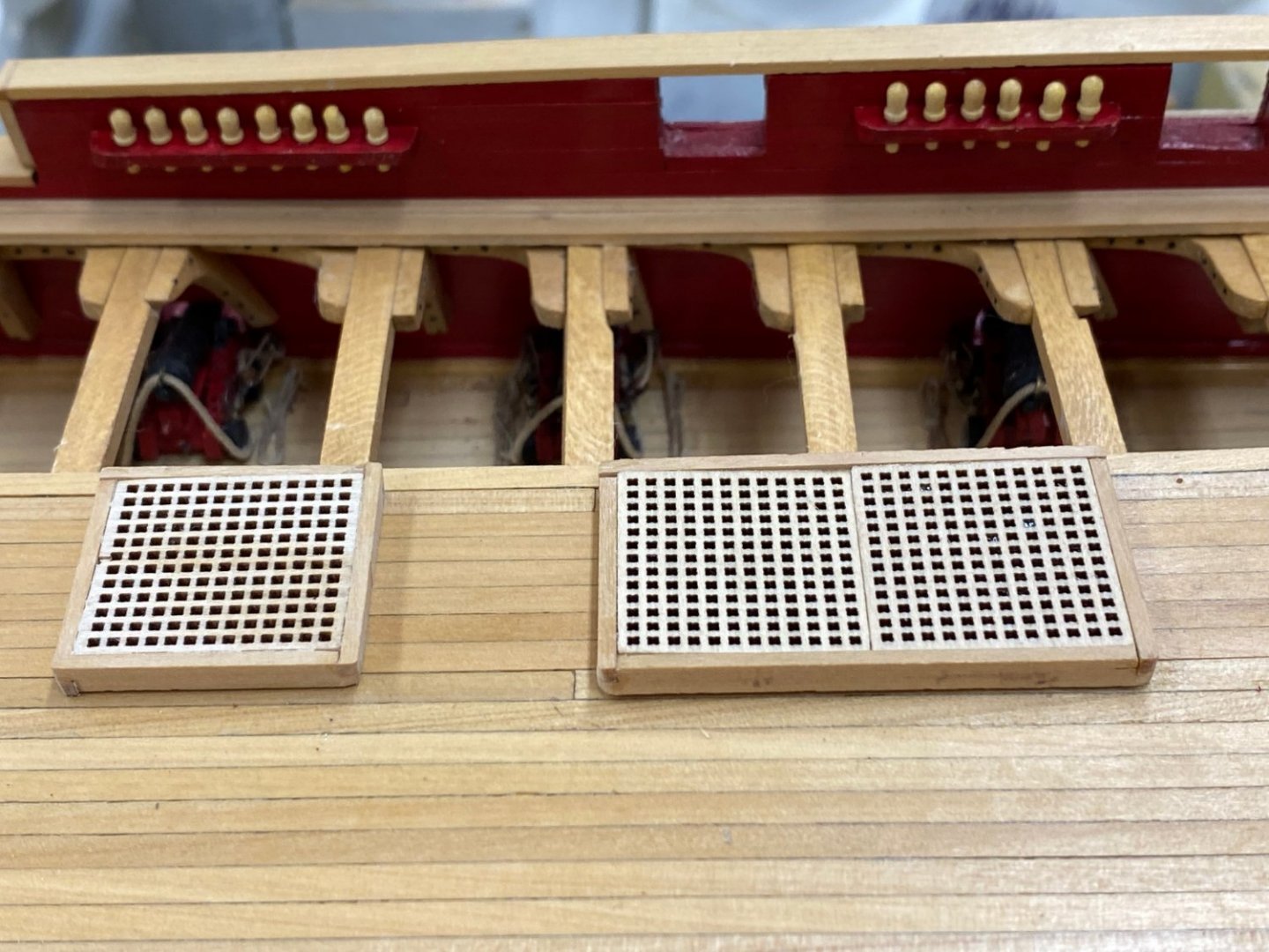
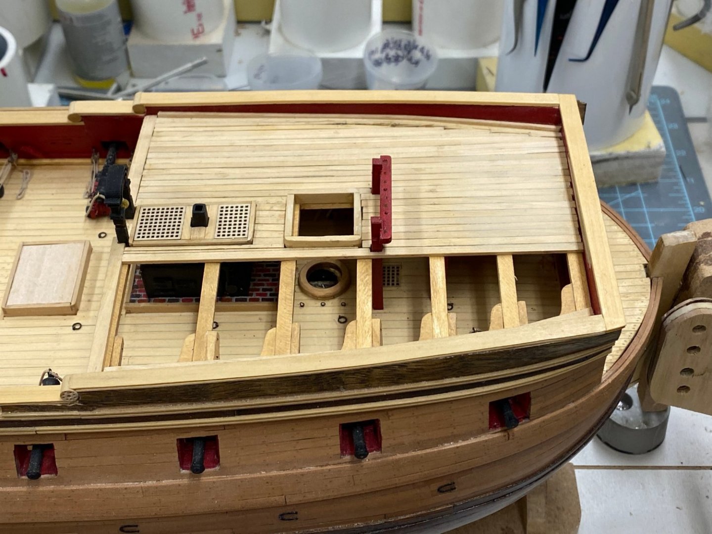
Having given the quarterdeck three coats of Wipe-on-Poly I installed the two hatch gratings. These are the "new" ones (only 1/8" high) since I chose to plank over the two hatchways between the main mast and companionway to the gun deck. I also added the pin racks and belaying pins as you can see on the bulwark. I decided not to use the kit provided (brass) belaying pins and opted for the 8mm boxwood pins from Model Expo. These are considerably wider than the kit provided ones and require a #53 drill bit for the hole. I tried to modify the kit provided pin rails and, while it was possible, the pins were so close together than it really did not look good. So I made new pin rails, the same length as in the kit but a little thicker and with fewer holes for pins. Since there is no rigging the number of belaying pins is not really important anyway.
- 370 replies
-
- 4
-
-
- Model Shipways
- Confederacy
- (and 1 more)
-
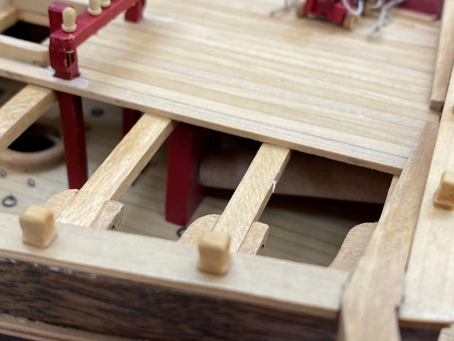
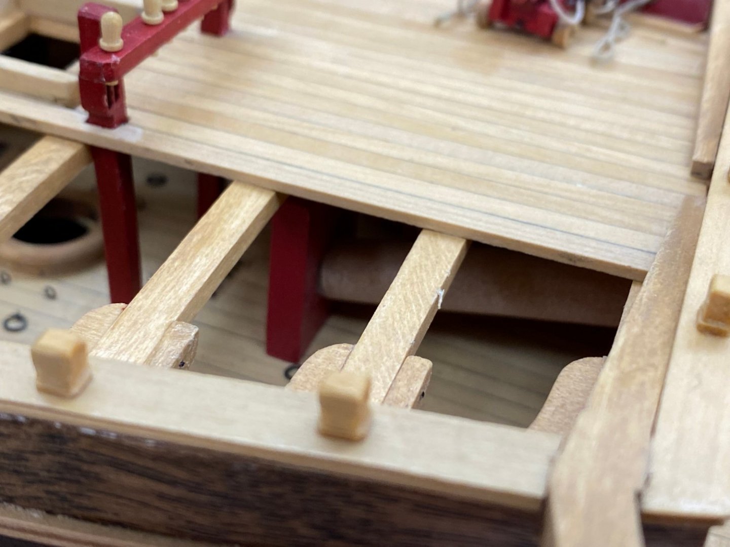
After some little bit of effort I completed the deck planking on the forecastle. I order to do that I had to install the hatches around the galley stove flue and the combing around the fore mast. And the forward set of bitts were installed previously since they are mounted to the gun deck. I built the belfry per the instructions but had a good bit of difficulty keeping the legs perpendicular to the crossbeam holding the bell. I finally decided to put a .025" piano wire in the bottom of each leg to help secure things when it is installed. So far so good, the belfry is installed - now for building the rest of the belfry structure. I cheated and added the 3/16" piece on top of the deck beam before installing the other posts for the belfry. Trying to put five notches alm ost all the way through a 3/16" wide by 5" long piece (of boxwood) a recipe for frustration and many ruined pieces. So I will have to adjust the length of the other four posts in the belfry structure. I suspected I would have to do this anyway some so "in for a penny, in for a pound" as the saying goes. Here is the forecastle with the hatch(es), half the fore bits and the center of the belfry structure in place. My plan is to have a gun (or two) on the forecastle to help hide my none to good nibbling job.
- 370 replies
-
- 4
-
-
- Model Shipways
- Confederacy
- (and 1 more)
-
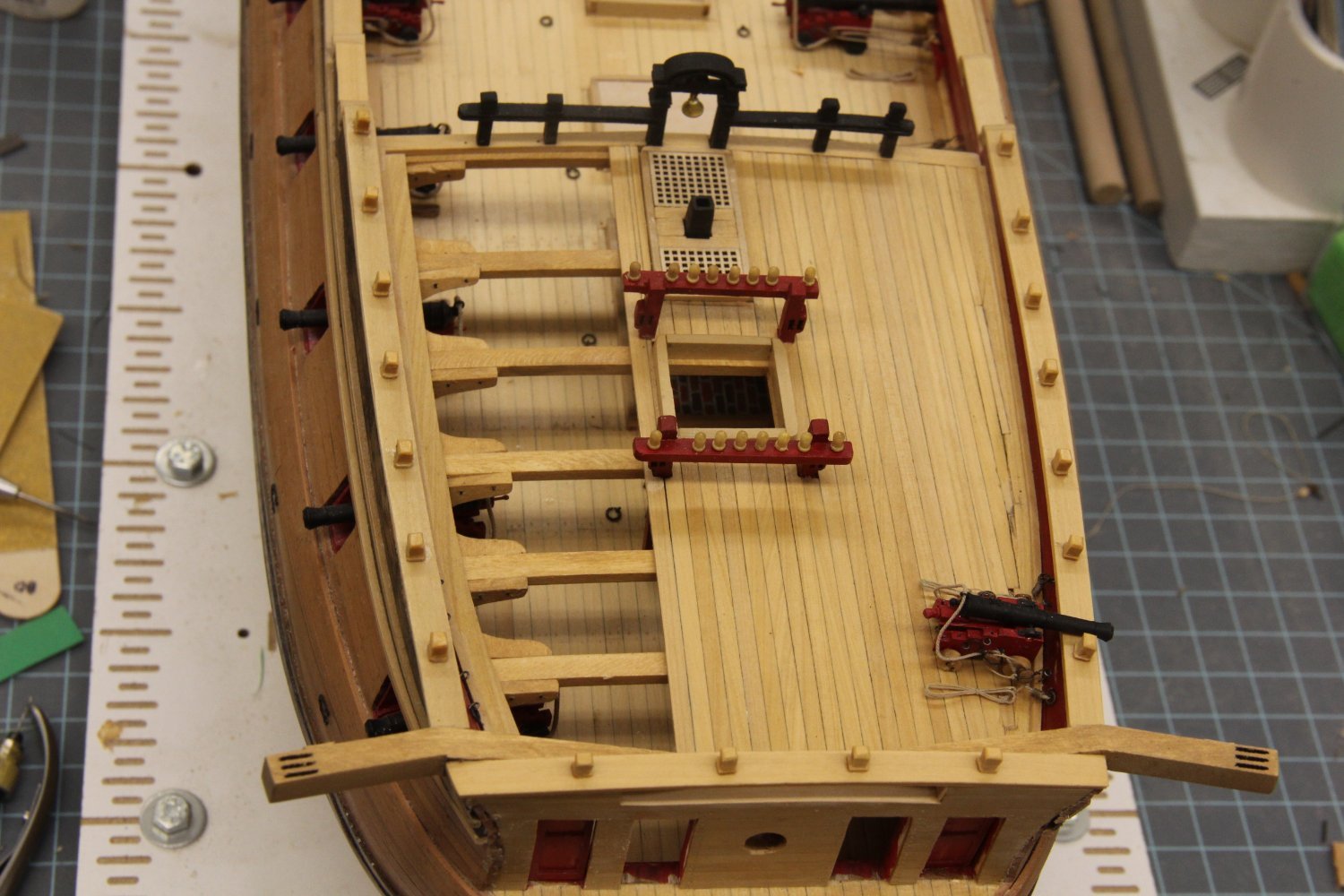
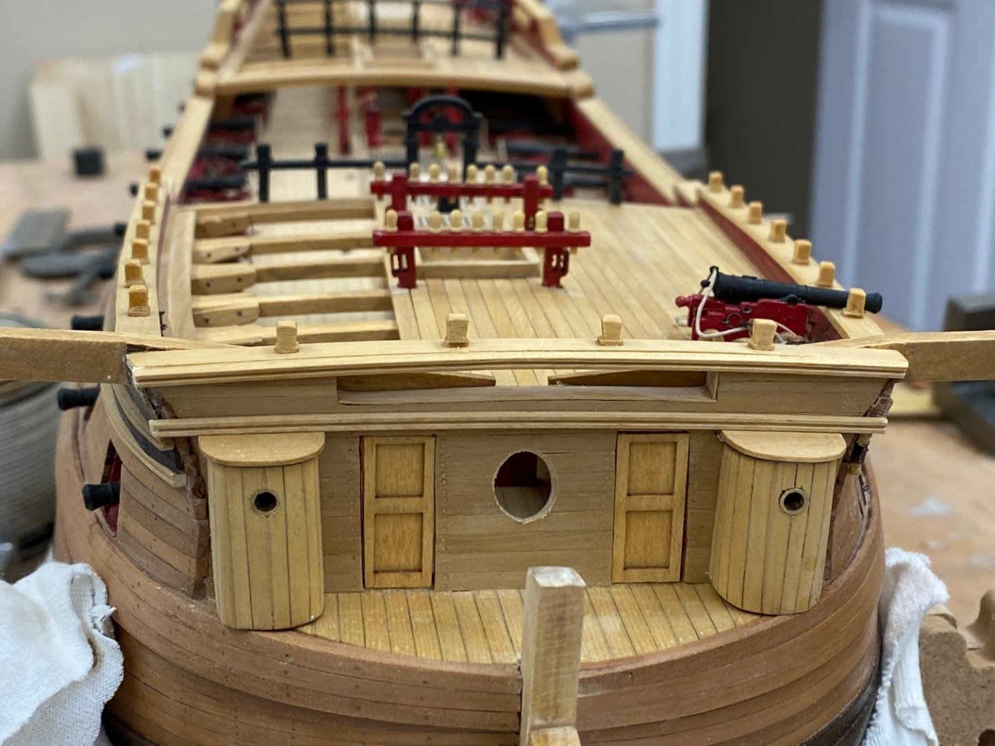
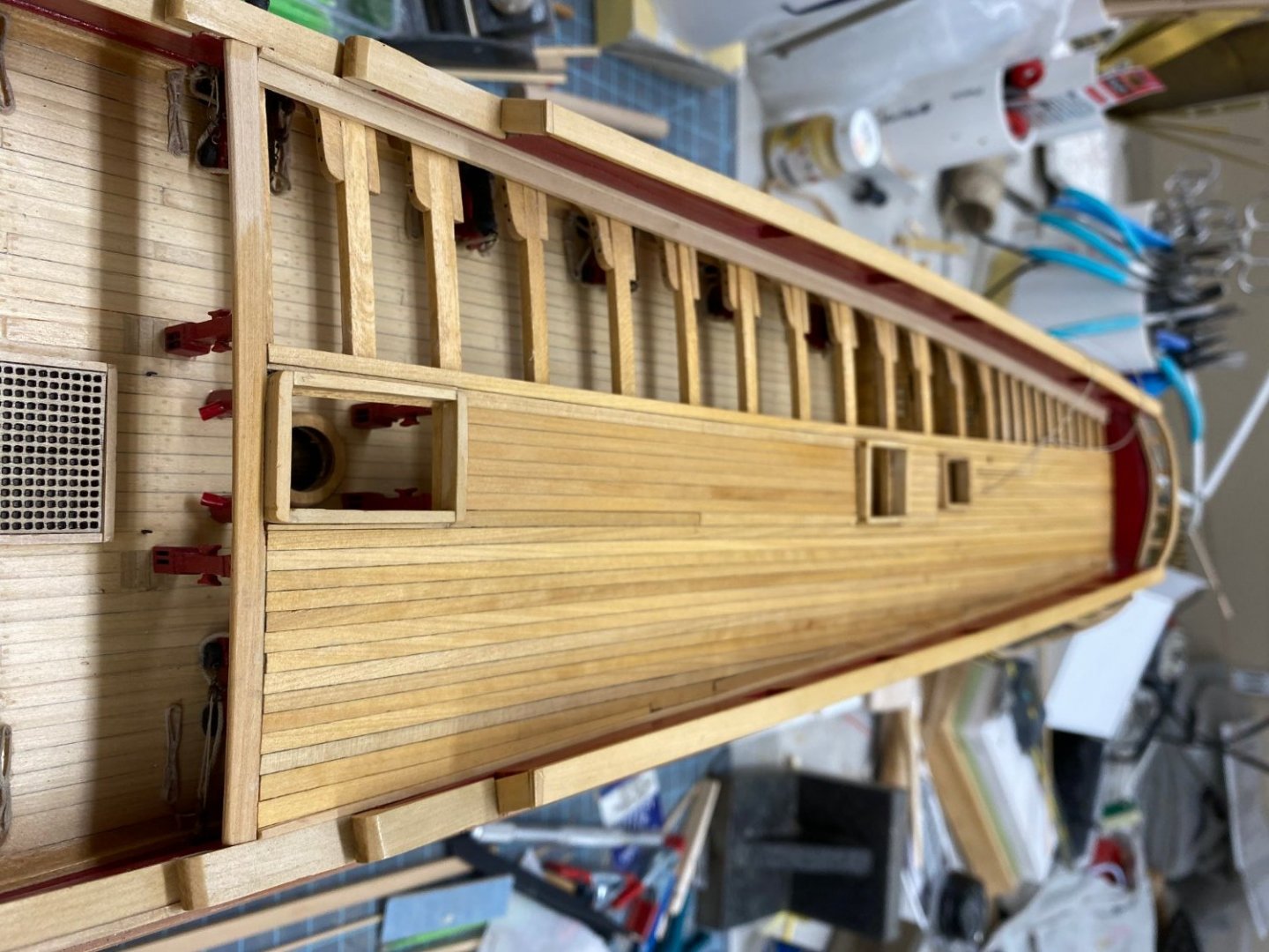
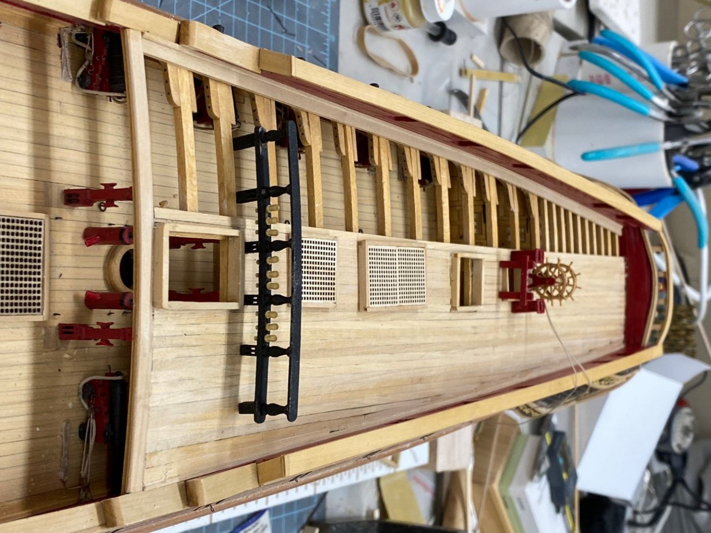
I figured out (belatedly) that I had built the forward portion of the fore rail (the one that mounts to the gun deck) using one of the pin rails instead of the intended, somewhat thicker pin rail provided. So I had to rebuild that before starting on the forecastle deck. At least I discovered it before I did the same thing with the after part of the fore rail. Both portions of the fore rail are awaiting their trip to the paint shop. In the mean time I placed the components (less the guns) that will go on the quarterdeck to see how things looked. Here's how it looks: Sorry about the orientation - it is correct on my MacBook so I don't know how to fix it. I also did a sanding of the quarterdeck with 220 grit sandpaper and here is how it looks after a wipe down with paint thinner. Wipe-on-Poly is next. Here is how it looks now.

- 370 replies
-
- 2
-
-
- Model Shipways
- Confederacy
- (and 1 more)