cdrusn89
-
Posts
1,916 -
Joined
-
Last visited
Content Type
Profiles
Forums
Gallery
Events
Everything posted by cdrusn89
-
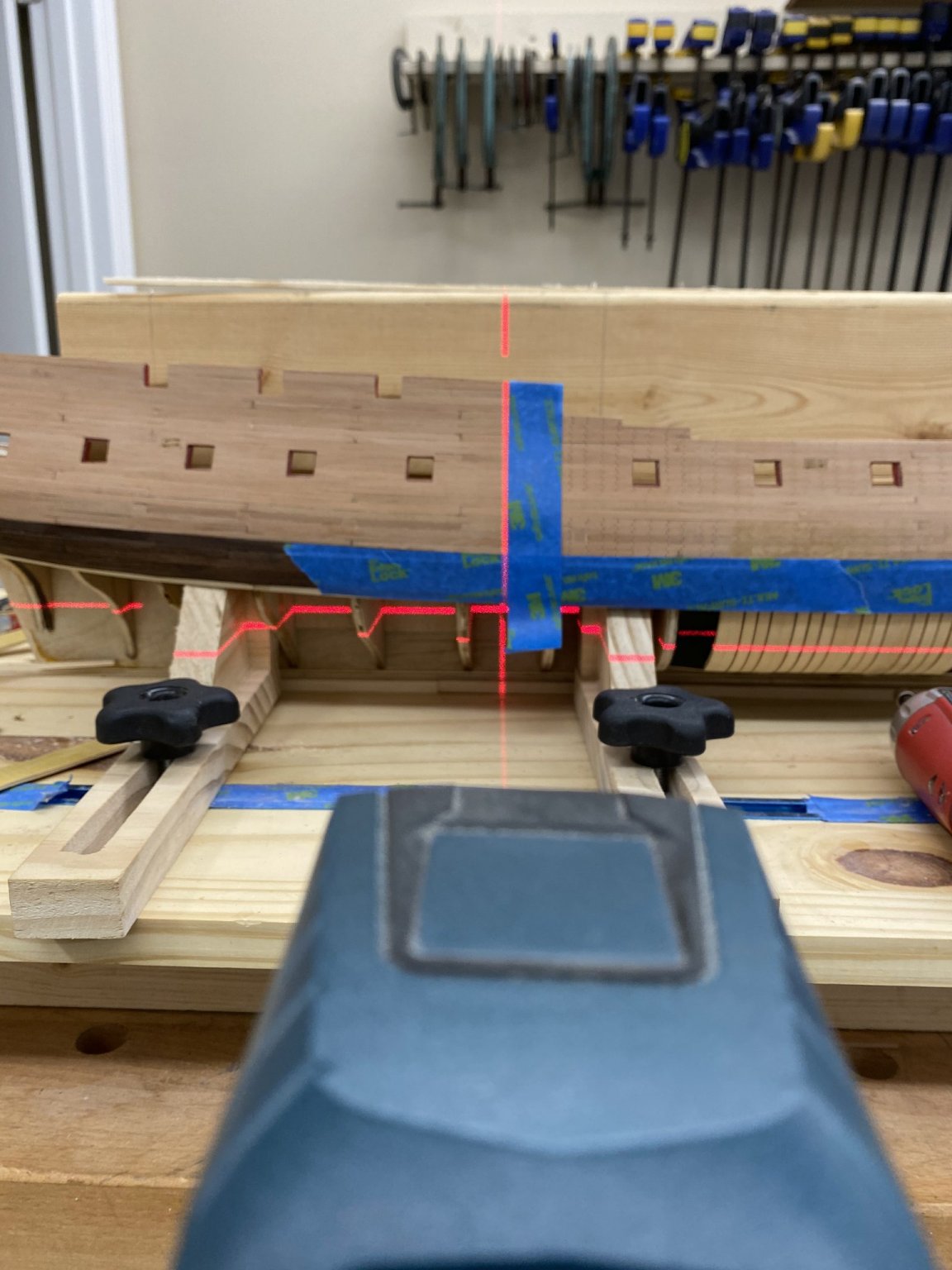
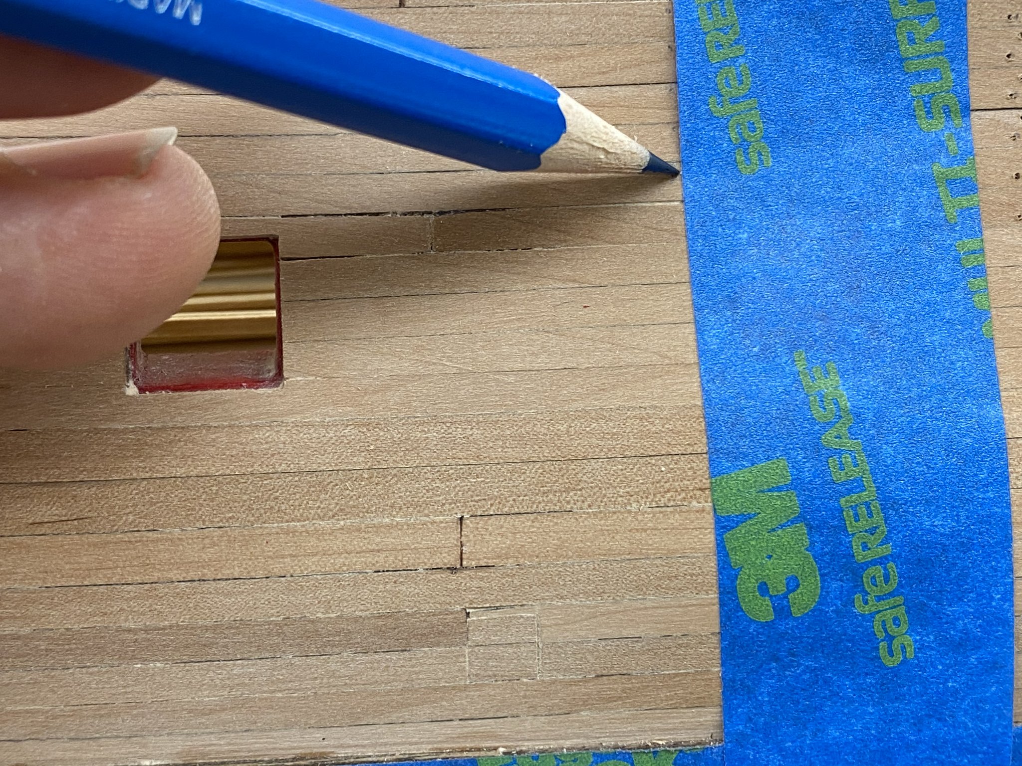
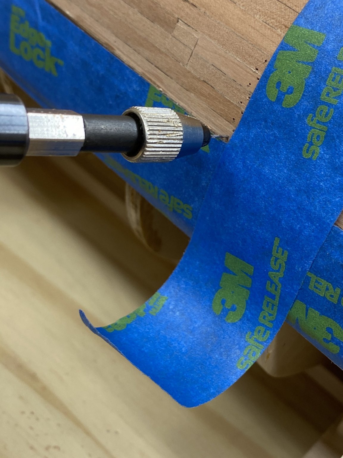
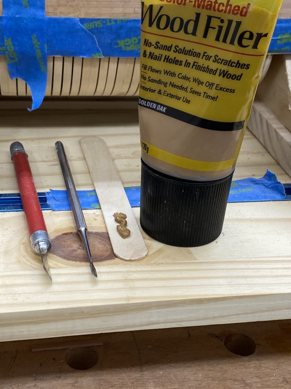
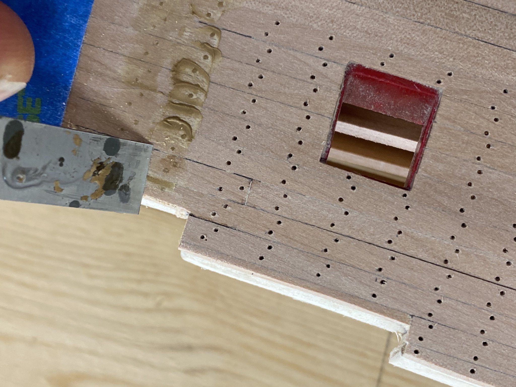
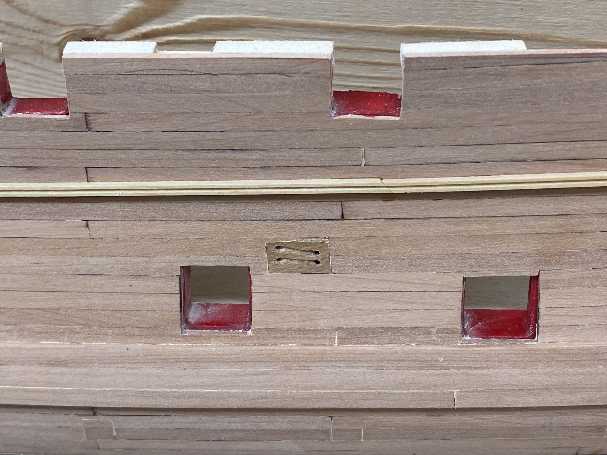
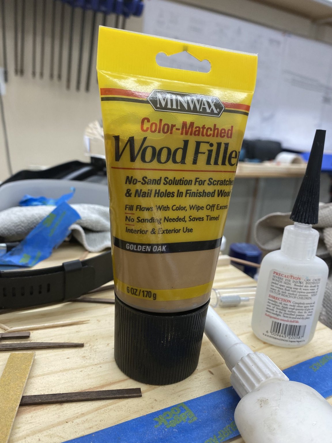
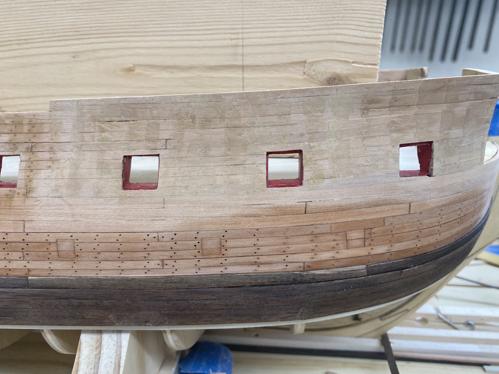
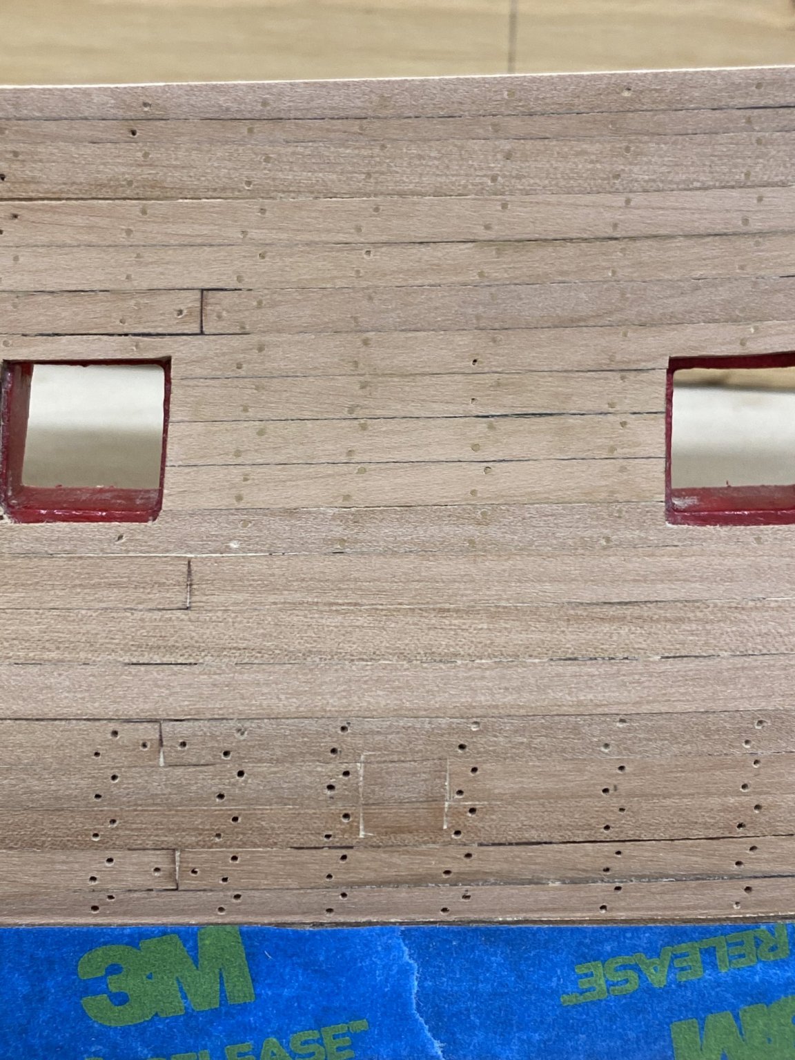
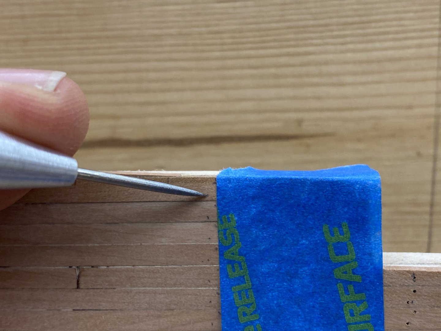
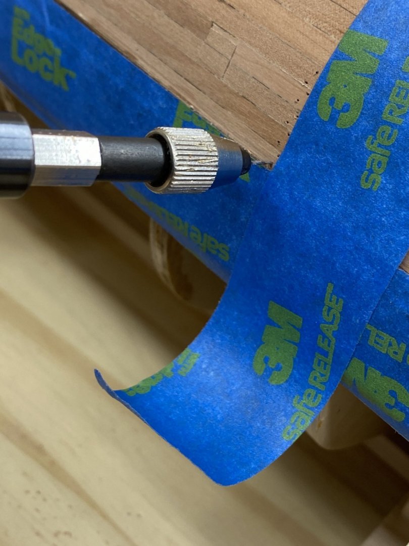
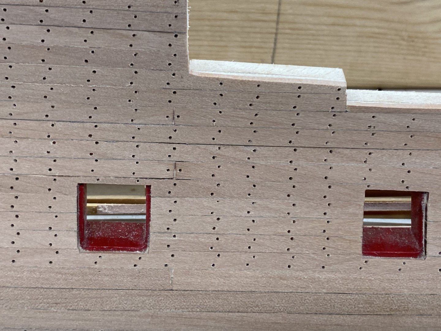
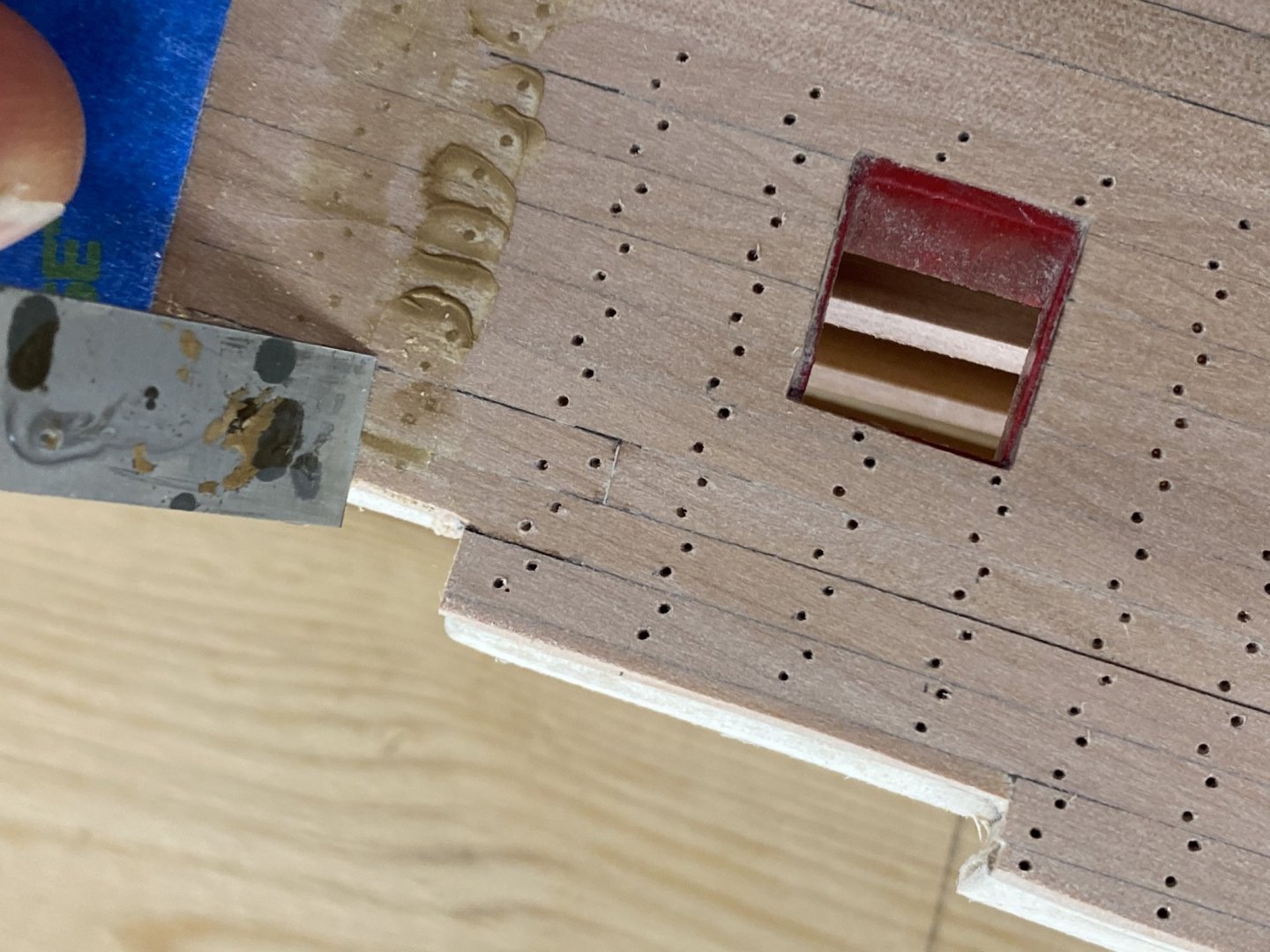
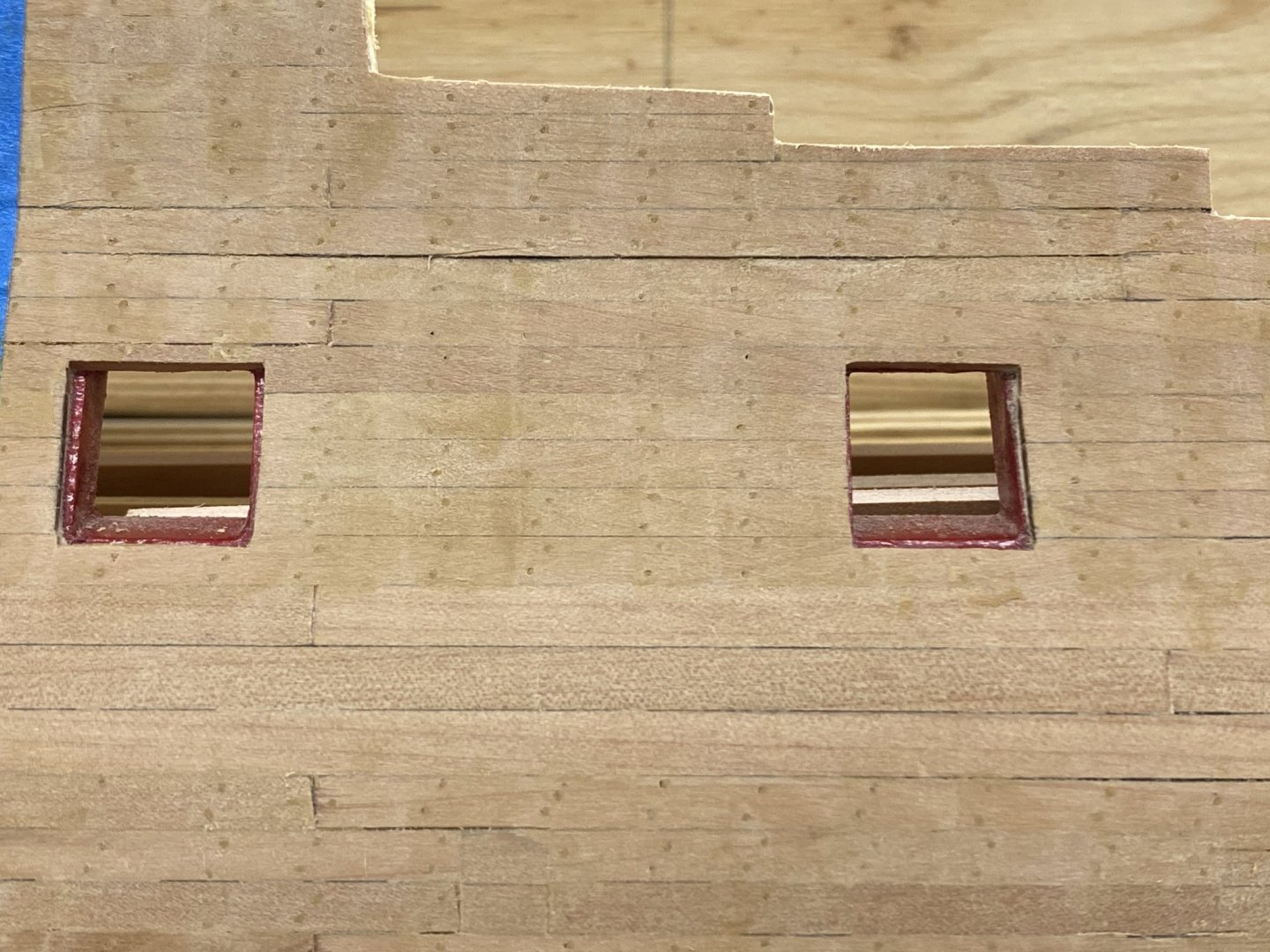
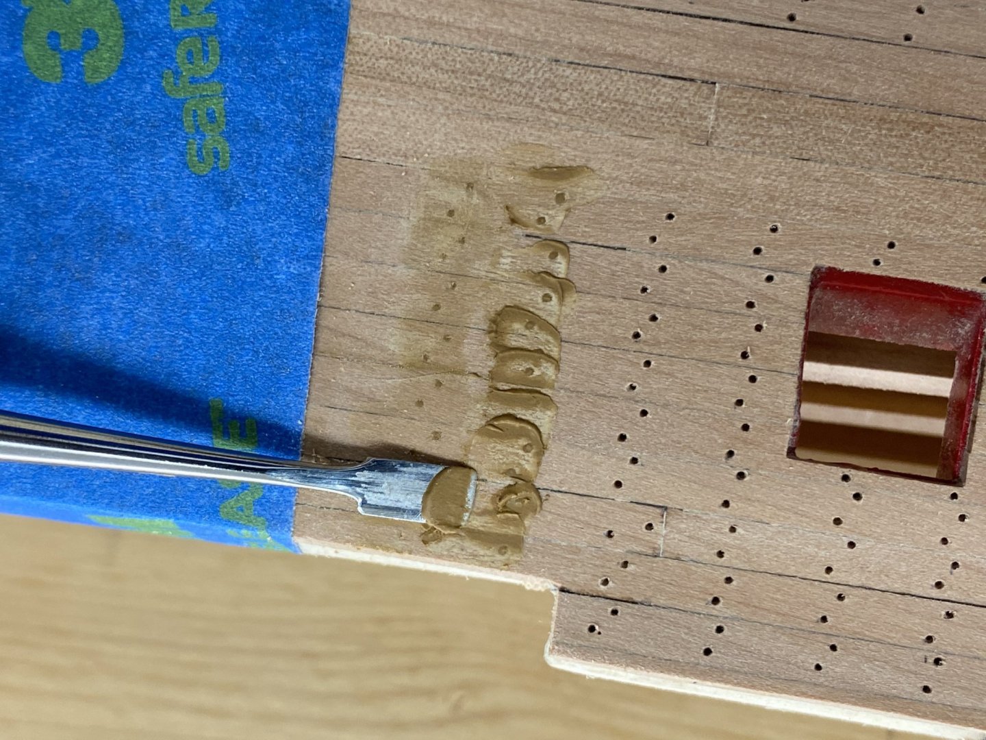
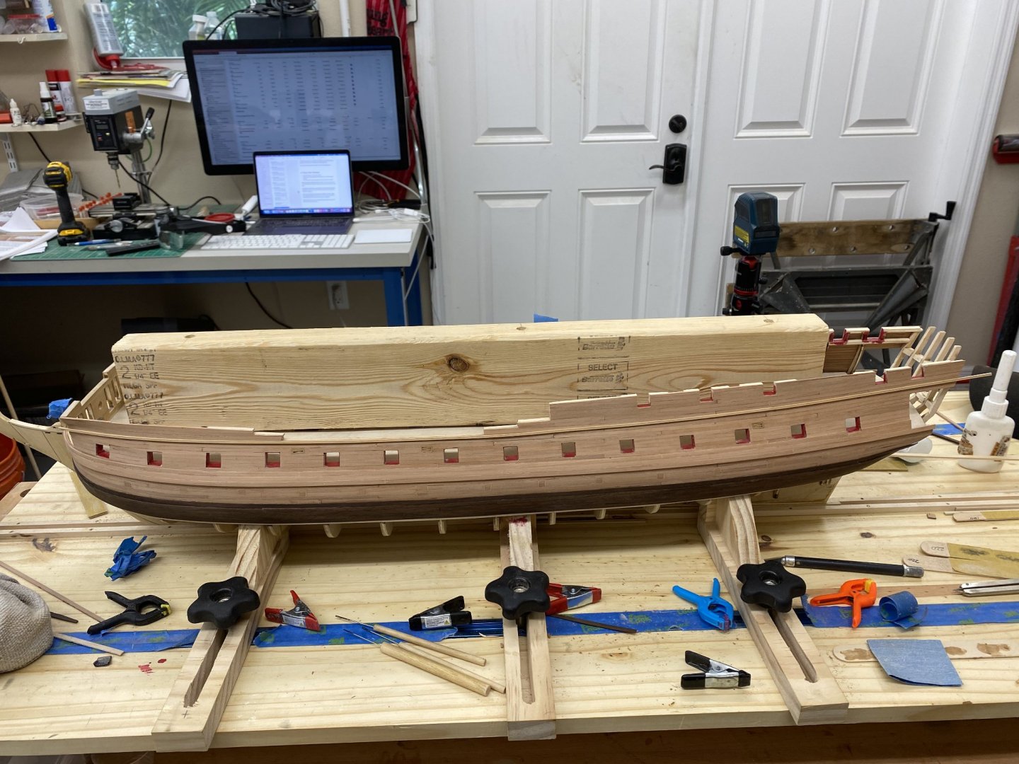
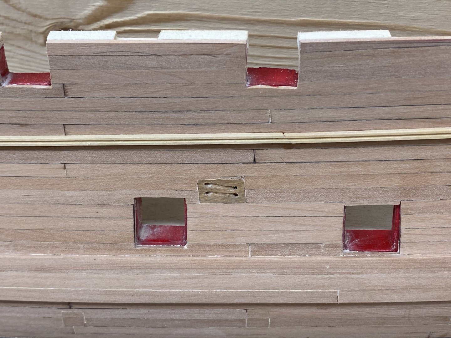
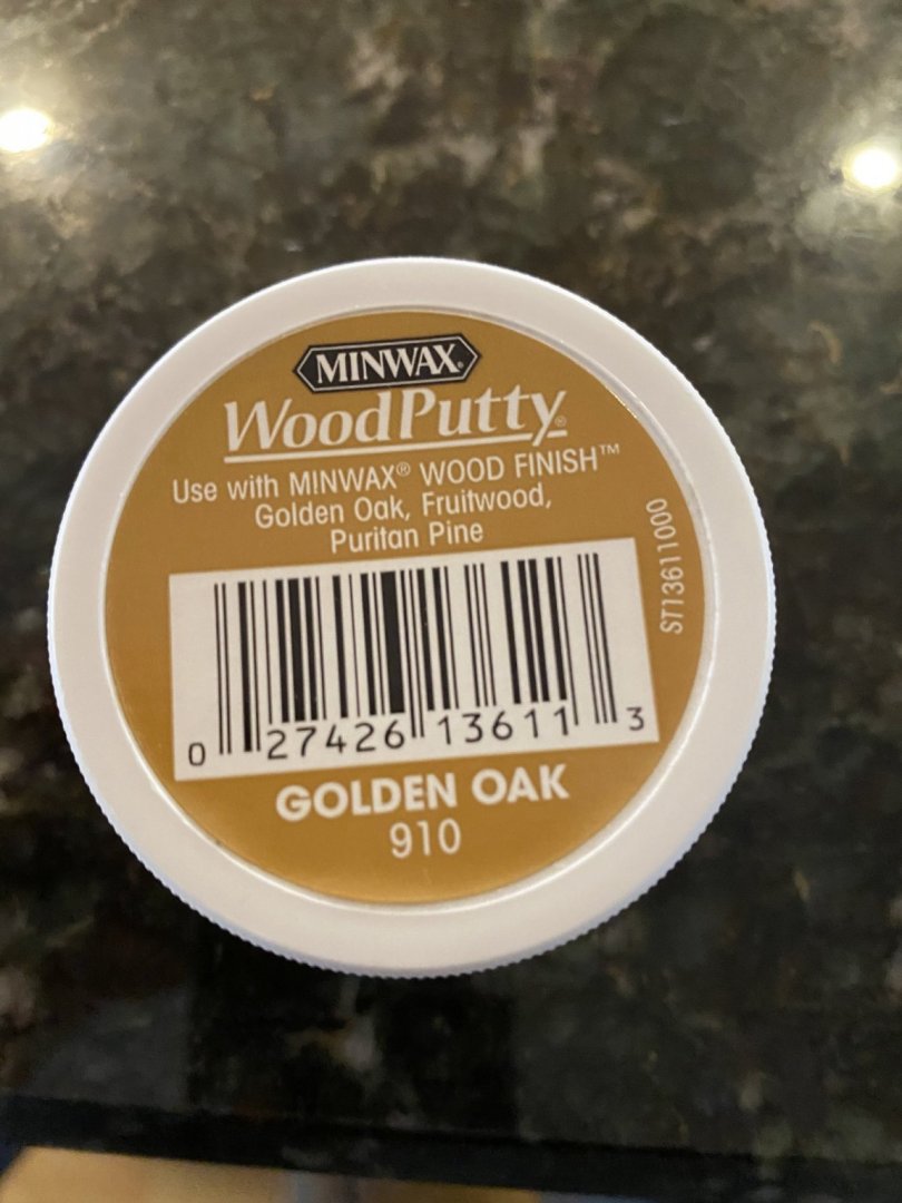
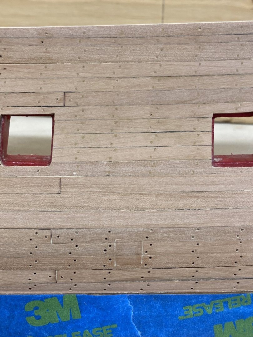
 Pressing on with the treenailing. In case anyone should be interested here is a description of how I did it. The instructions are pretty good but since I am using Swiss pear and not staining the kit supplied basswood I had to adapt them in some areas. I picked the spacing for each vertical row of treenails from the plans and then replicated that spacing all along the hull. I had to be carefully not to put treenails in the sweep port doors and adapted a bit around the gun nports depending on where the vertical rows landed near them. With the locations marked along the top of the bulwark I placed a strip of masking tape vertically and used my laser level to make sure the tape was "vertical". Then I used a shape 2H pencil to mark where each treenail would go, approx 1/32" down from the top and up from the bottom of each plank with the bottom one offset about 1/32" to the left of the upper one. With the locations marked I used a sharp awl to make a shallow "divot" on each pencil mark. This makes it easier to get the drill started where you meant it to start. Do not ask how I came to this realization. Then I drilled out each hole with a #75 drill bit using my old Wen power screwdriver. Since it is rechargeable I find that one charge is good for about 300 holes so that provides a stopping point before muscle cramps become a serious issue. I use the awl to clean out each hole. After I get tired or the drill runs out of battery I sand the area with 220 sandpaper, vacuum with my small vacuum and then go back over each hole with the awl to clean out any remaining sawdust. Here is a section ready for filler. I use the Minwax wood FILLER (not putty) - Golden Oak color in this case. I squeeze a small amount onto the tongue depressor. I use the small chisel to apply the filler to the holes trying to keep it off the surrounding planks as much as possible. Sorry for the upside down picture - it is right side up in my photo file and app. And changing the orientation in the photo app and reloading it does not change how it shows here. Go figure? I use a chisel blade Xacto to remove as much of the surface filler as possible before it dries (which happens pretty quickly. Again sorry for the upside down picture And here is a section after the filler has been applied. I will sand again with 220 (and maybe 320) before applying the Wipe-on-Poly finish. Actually the treenails are more noticeable in the picture than in"real life" but it is probably the lighting in the shop or my aged eyes playing tricks. Anyway this is how I am doing the treenails. Certainly not the only way just MY way.


- 370 replies
-
- 4
-

-
- Model Shipways
- Confederacy
- (and 1 more)
-
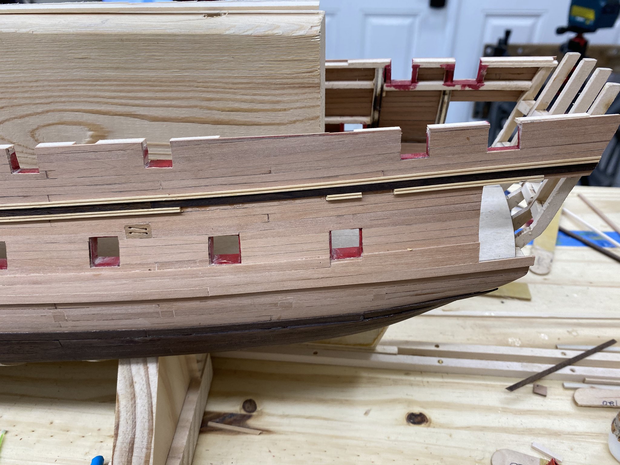
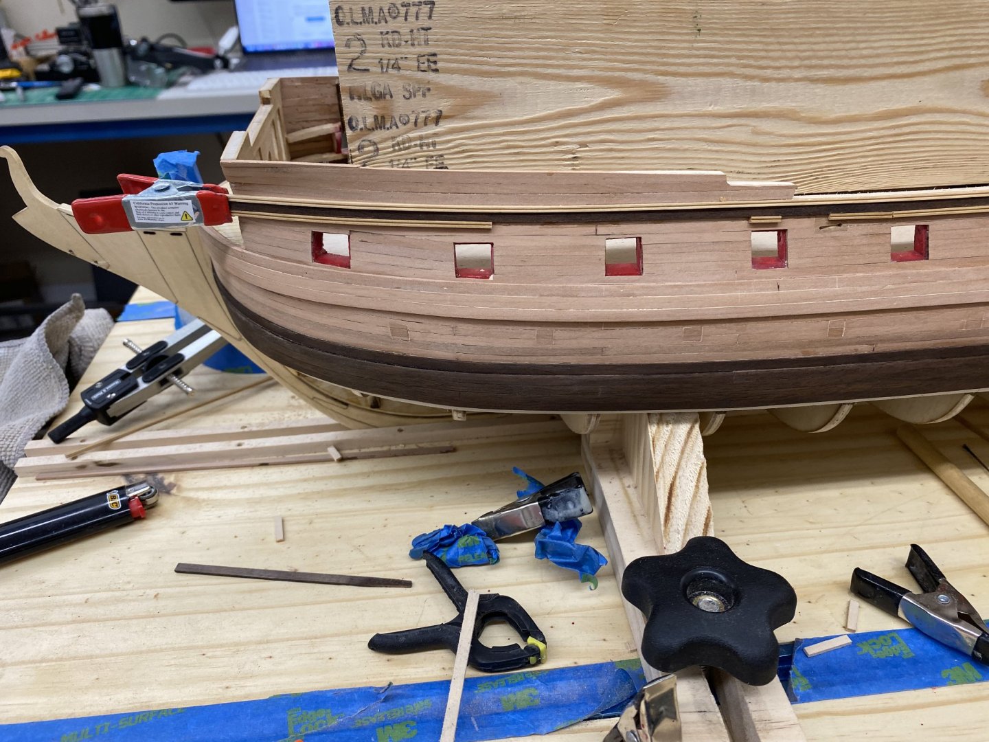
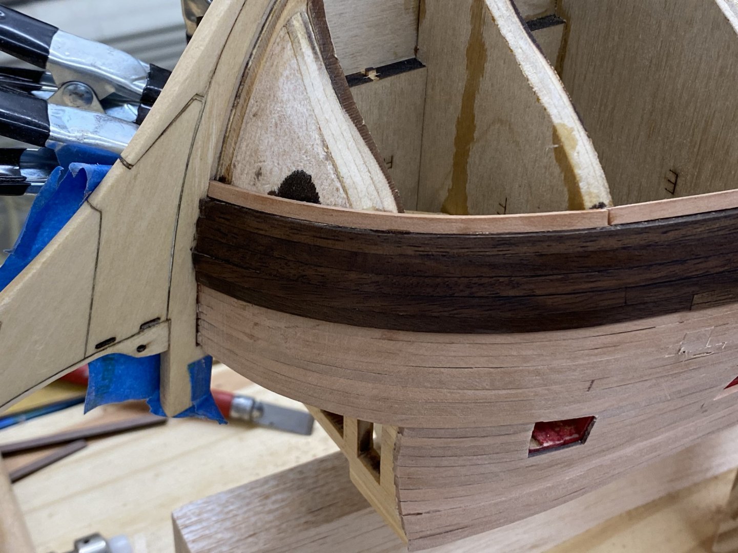
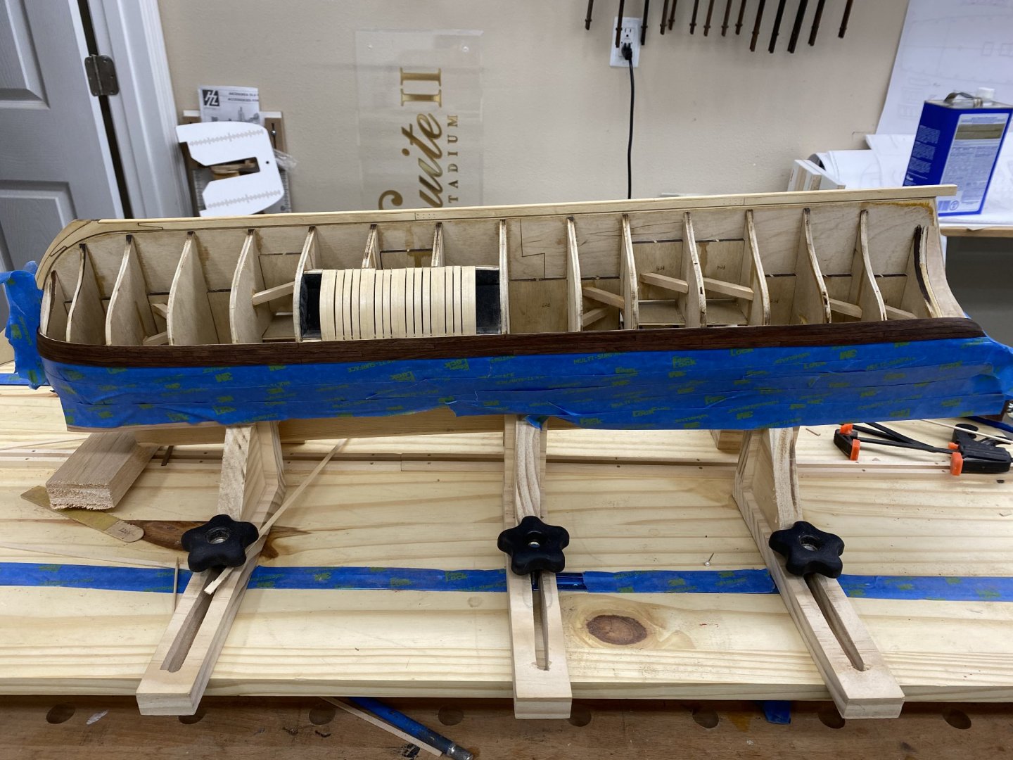
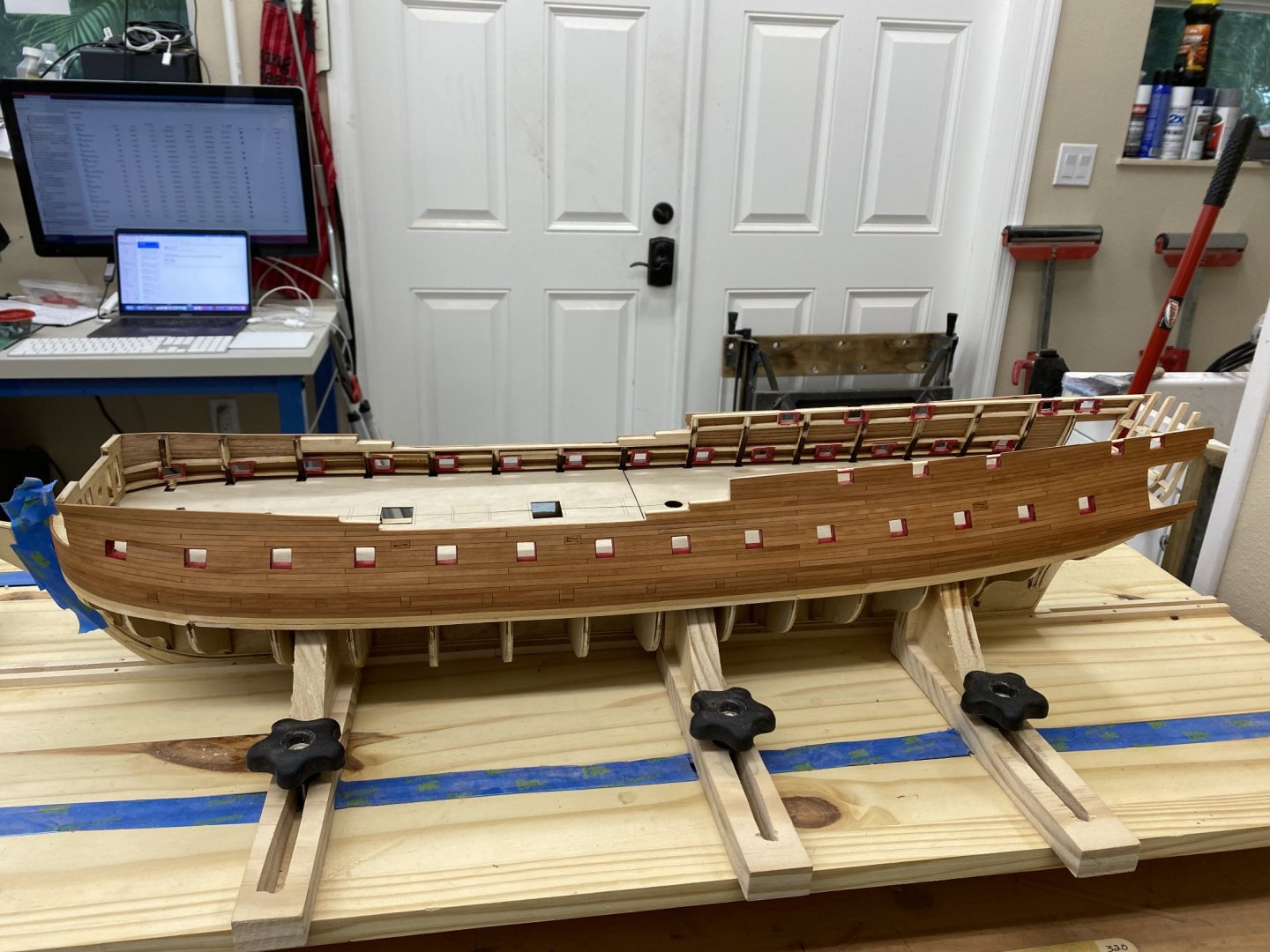
I am really tired of drilling holes for treenails. I am about half done on the stbd side and have been focusing on the port side to avoid more "holes'> So I completed the molding that runs along the lowest railing is place (see pictures above). I cut some short (1/2 - 3/4") pieces of 1/4" x 1/16" stock to act as spacers and used them to clamp the lower piece of molding, spacer and upper molding in place. Then I put drops of thin CA on the junction of the lower molding and the hull planking being carefully to not get any on the spacers. I used an applicator made from a sewing needle with half the eye filed off. When the CA dried (almost instantly) I moved the spacers around and applied more thin CA where the spacers had been. If I had been smarter I would have marked the locations where the channels are going to be since lower molding only runs between the channels. Eventually I figured this out (thanks Bossman) and cut out the offending molding before I got any further down the road. I am using walnut to "simulate" the areas painted black on the prototype so I ran some 1/4" wide walnut stock through the thickness sander down to a bit less than 1/32" thick. I applied walnut stain to get my stock a bit darker than it would be naturally and to reduce the variation in the color. At the moment it is just "wedged" between the two sets of molding. I plan to remove it and apply a couple of coats of WoP then glue it to the hull. Here is what the port side looks like at the moment. Now back to drilling treenail holes.
- 370 replies
-
- 4
-
-
- Model Shipways
- Confederacy
- (and 1 more)
-
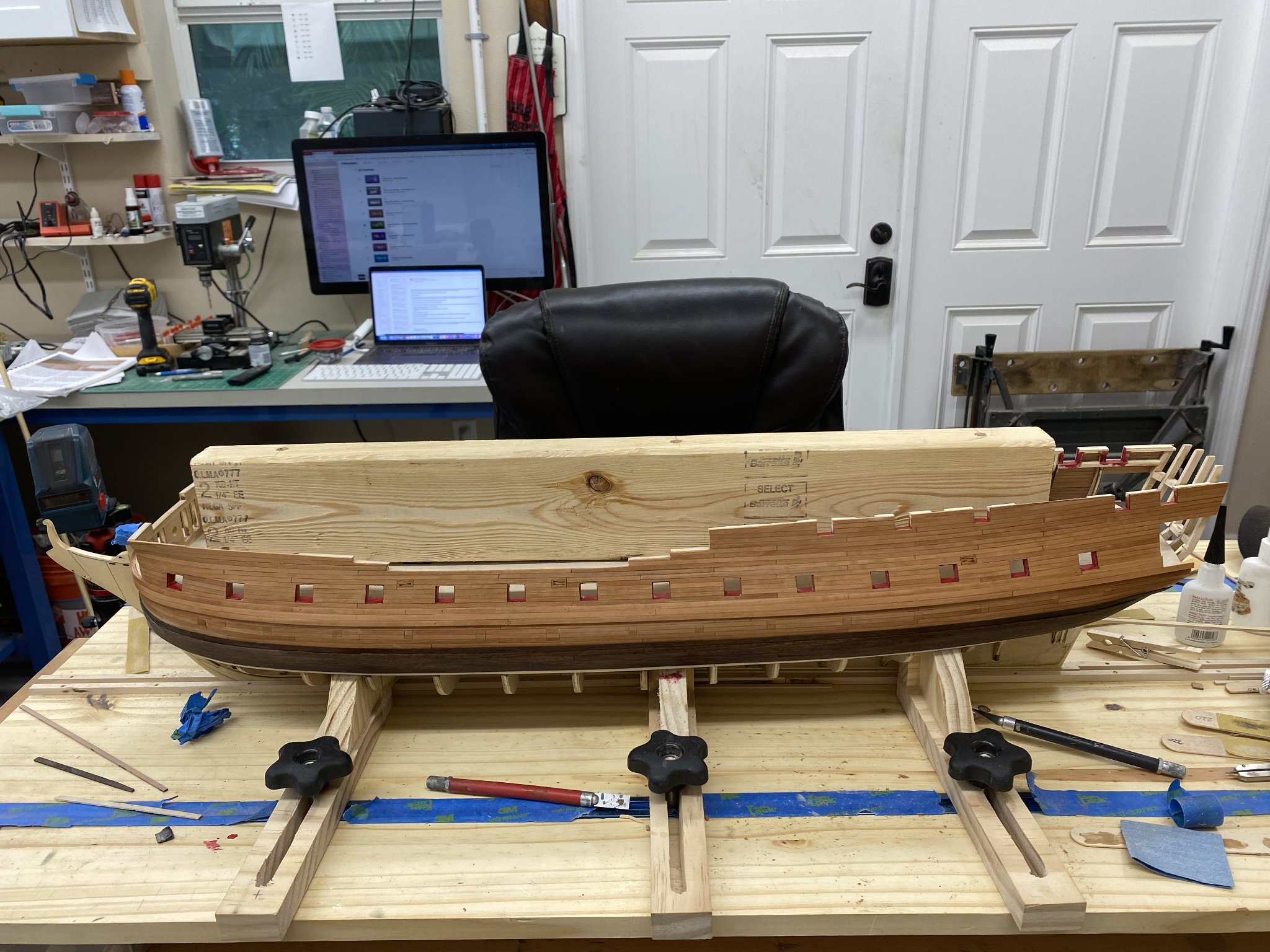
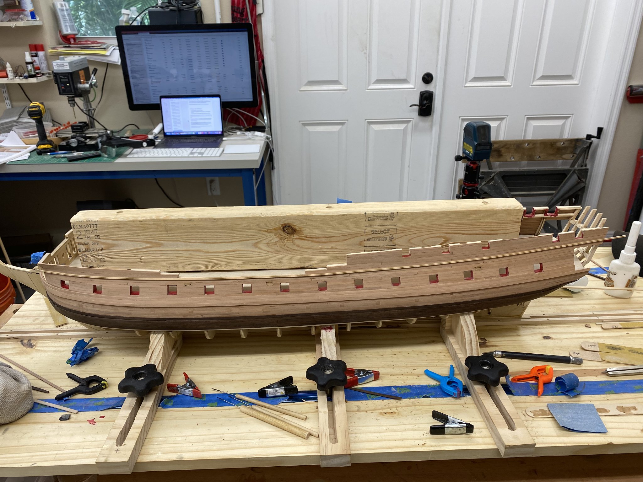
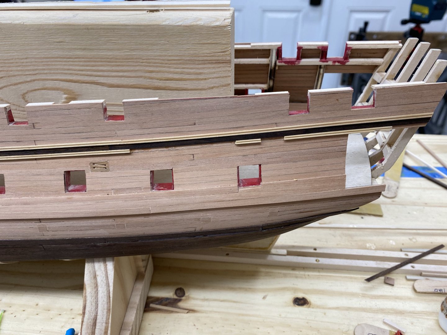
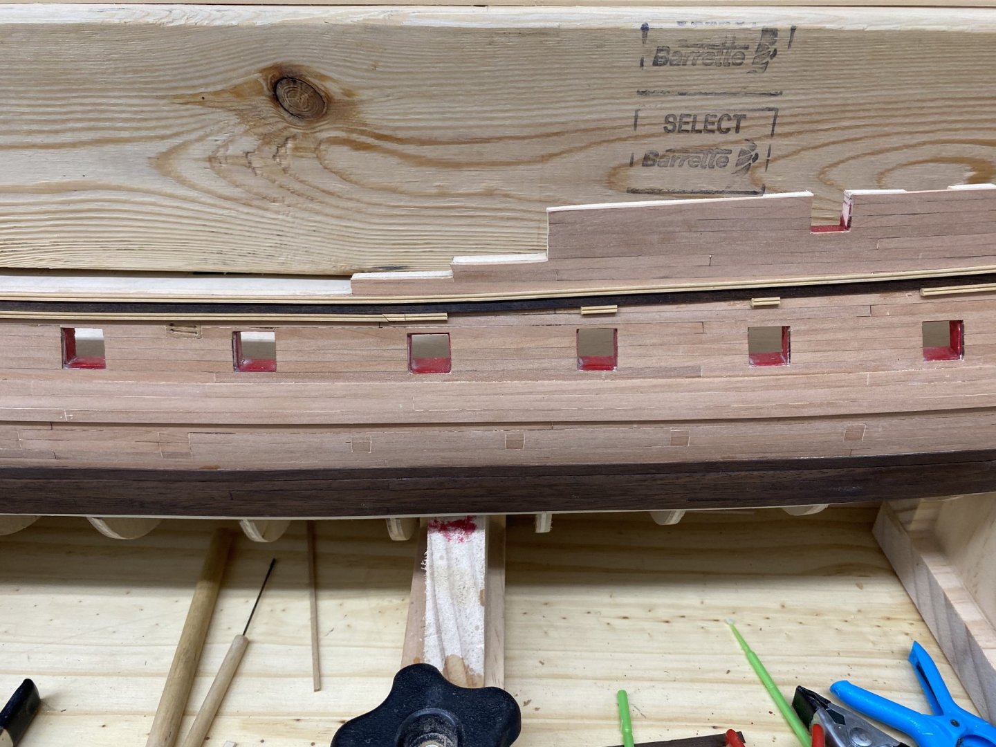
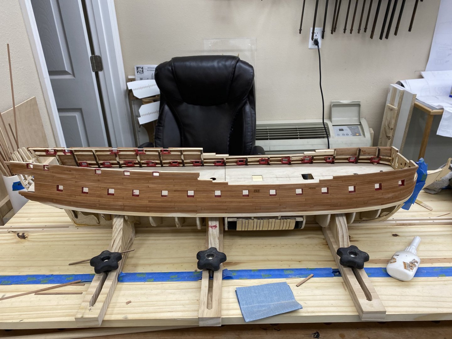
While continuing the seemly endless treenail hole marking, drilling, sanding, filling and sanding again (and again) I have been working on the port side (no treenails on the port side) too. I got the upper wales installed and sanded and the black strake so this side is pretty much done as far as the bulwark structure and planking are concerned. So here is the port side after a wipe down with paint thinner to approximate what it will look like after the WoP. The dark line along the center of the bulwark is the shadow of the upper wales from the overhead lights. I had to look after I saw the picture to make sure it was not something else (aka BAD!). So next for the port side is the "Fancy" molding. I decided to use boxwood for the molding as it is much easier to use the molding cutters on than the basswood. I used Artisia Latina cutters instead of the ones that came with the kit. I was going to use some 1/16" X 1/16" boxwood strips I had on hand but the Latina cutters are sized in metric (the double round - similar to what comes with the kit) is sized for 2mm X 2mm blanks. Rather than run the risk of the center "wandering around" on the marginally narrower 1/16" boxwood I cut some 2mm X 2mm blanks and they worked like a charm. The cutter generates a considerable amount of heat when you pull a 24" length of boxwood through. Enough to surprise me as I held one finger on top of the blank to keep it pressed onto the cutter. Anyway I cut the molding for the port side and left the setup in place as I will have to do the starboard side soon (hopefully). Here are two shots of the first run of the Fancy molding on the port side. I did not glue the ends down as it is not clear where the molding will end, especially at the stern.

- 370 replies
-
- 5
-
-
- Model Shipways
- Confederacy
- (and 1 more)
-
Treenails are not much fun. Especially if you do not carefully read the instructions on the product you choose to fill the holes. Based on the color I planned on using Minwax "WoodPutty" ,in the Golden Oak color to fill the holes in the Swiss pear. However, this product (after you read the instructions on the back) "Will not harden to a sandable surface." I had used this product on a small sample board and apparently never noticed an issue. However, when I tried it on a section of the bulwarks it did not work out so well. I eventually had to drill out all the holes a second time and apply the Minwax Wood FILLER which luckily comes in the same Golden Oak color. So here is a section with the correct filler. And here with the filler sanded down The real test comes after the WoP is applied but I am reluctant to do that until the entire hull has all the treeenails installed (including in the upper wales which will be installed after the rest of the hull/bulwarks are treenailed). But here is what the sample looked like. (The left side used walnut filler which I judged to be too dark).


- 370 replies
-
- 1
-
-
- Model Shipways
- Confederacy
- (and 1 more)
-
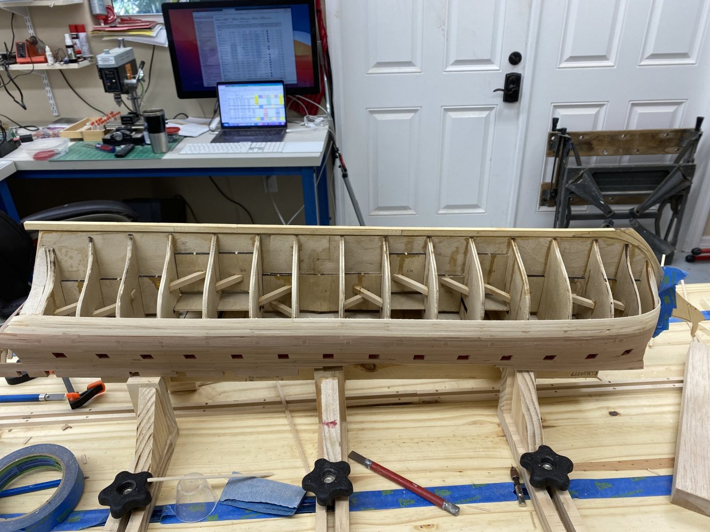
Although I put a piece of Swiss pear under the wales I have decided to use Holly for the hull planking. The near white color will (hopefully) not need painting to simulate the tallow mixture that was used before coppering. It will also provide additional incentive to do a good job on the planking since there will be no opportunity to cover up errors with paint or filler. So I replaced the piece of Swiss pear on the starboard side and started with Holly on the port side. I have to mill the 80 or so 24" pieces of Holly I will need for the hull planking but had a few pieces I milled as a "test" so decided to start with them. I can mill the holly to spell myself from doing the treenails on the starboard side. Here is a shot of the Holly on the port side.

- 370 replies
-
- 5
-
-
- Model Shipways
- Confederacy
- (and 1 more)
-
Very nice Mark. An outstanding example. I can only hope mine turns out as well.
-
Starboard side bulwarks and wales are complete. I will wait on the upper wales until I get the treenails done - easier to keep things aligned (I hope). And yes I did notice that one of the gunport doors has come out - no idea where it went or when it came adrift. Another "project" to add to the list. I decided to use the same walnut for the "black strake" as for the wales (but 1/32" instead of 1/16"). Stern did not come out as well as I had hoped but it will "do". Working the port side now. Will do the treenails on the starboard side. To keep from going crazy I may start the stove or some other piece while working the treenails. I am having trouble imaging drilling the thousands of holes (not to mention sanding the entire bulwarks again) without something else to break up the job.


- 370 replies
-
- 3
-
-
- Model Shipways
- Confederacy
- (and 1 more)
-
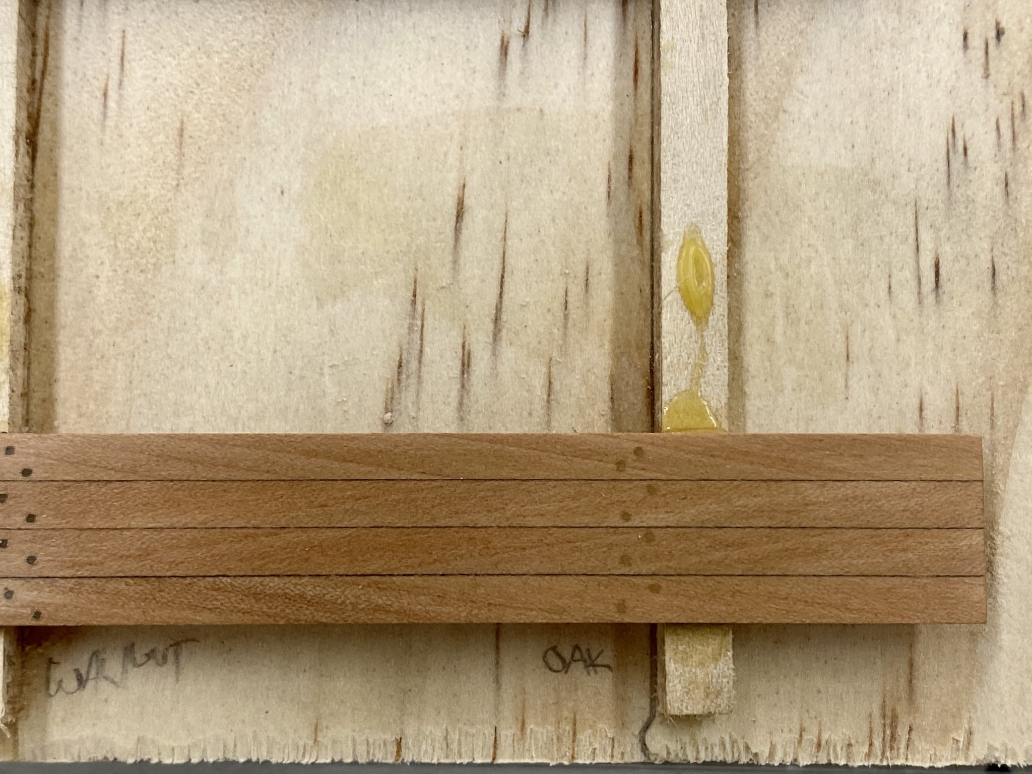
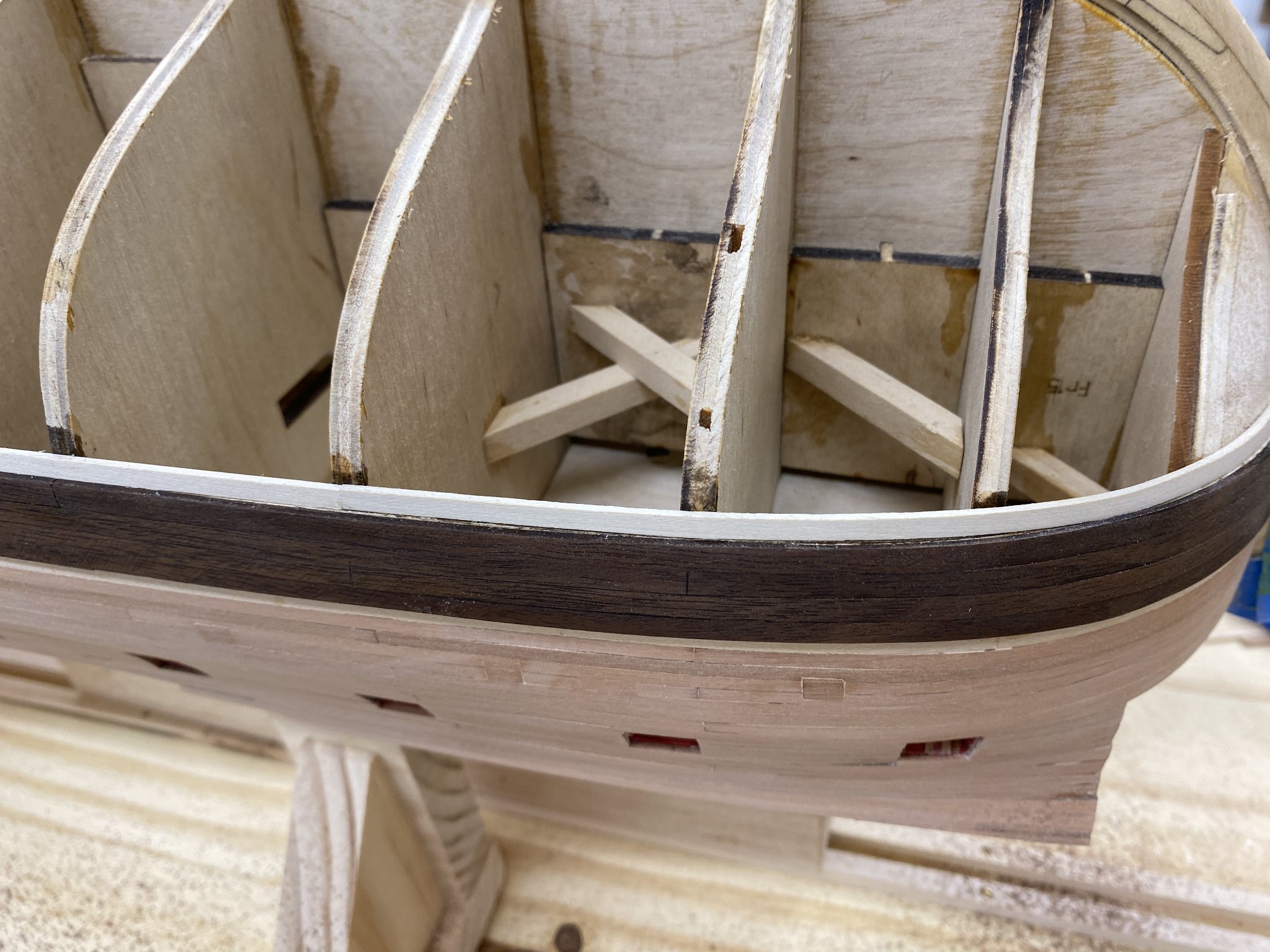
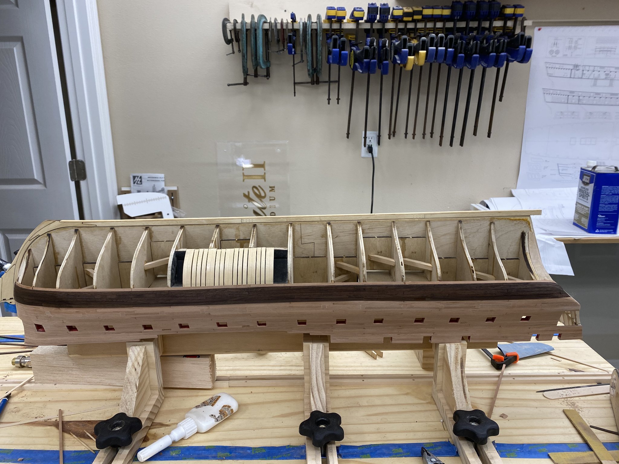
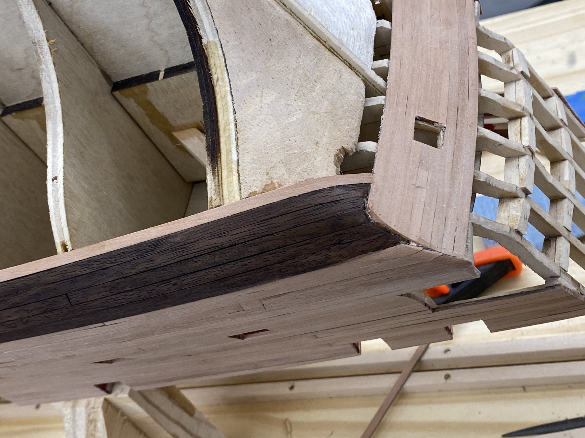
After some consideration I decided to add the four rows of 5/32 X 1/16" planking to the main wales before proceeding further on the hull planking. I used walnut material that I cut to the required dimension and had stained with walnut Minwax stain to get it closer to black. I am not sure what planet I thought I lived on that would allow me to just glue these pieces on over the basswood and be "done". Obviously there is some (in places a good bit) of sanding that had to be done to get the walnut pieces to conform to the underlying planks. I am now on the fence about whether to add the walnut stain or just go to the WoP now that I have the walnut back to the unstained state (after what seemed like considerable sanding). Here is the stbd side with the walnut in place and the rest of the hull protected by masking tape in case I decide to go with the walnut stain. I have pieces of 5/32 X 1/32 walnut (with the stain) ready to install as the "Black strake" but can go with Swiss pear as well if that looks better.
- 370 replies
-
- 5
-
-
- Model Shipways
- Confederacy
- (and 1 more)
-
Bossman - Thanks, I was planning on using Boxwood as you did. I will carefully place the glue where it will (hopefully) make getting it off when the time comes. Following the instructions I added the three additional 5/32" planks at the below the two that started the bulwark planking. Here is the port side. I am trying to decide whether to add the additional wales planks now or wait. It is my intention to make the additional main wales planks out of walnut (and stained with walnut stain) rather than painting them black. I am starting to think it might be best to do that now and then get at least one coat of WoP on the entire assembly before doing the hull planking.
- 370 replies
-
- 1
-
-
- Model Shipways
- Confederacy
- (and 1 more)
-
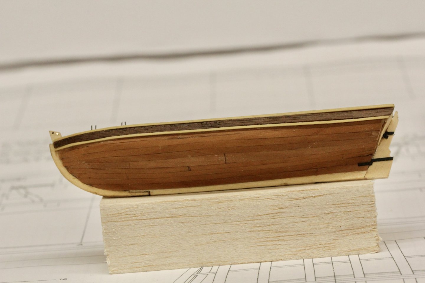
Thanks Captain. The Wipe-on-Poly finish does not make the Swiss pear as dark as the paint thinner does but it is certainly darker than the pear without any finish. Here is one of the ship's boats with pear planking and walnut stripe. Hopefully this is close to what the ship's hull will look like.
- 370 replies
-
- 3
-
-
- Model Shipways
- Confederacy
- (and 1 more)
-
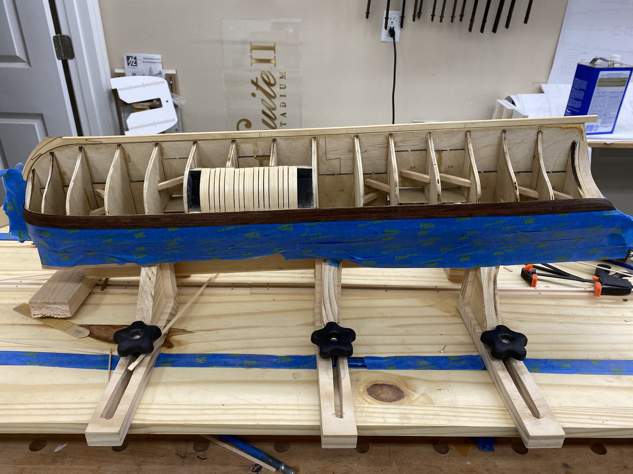
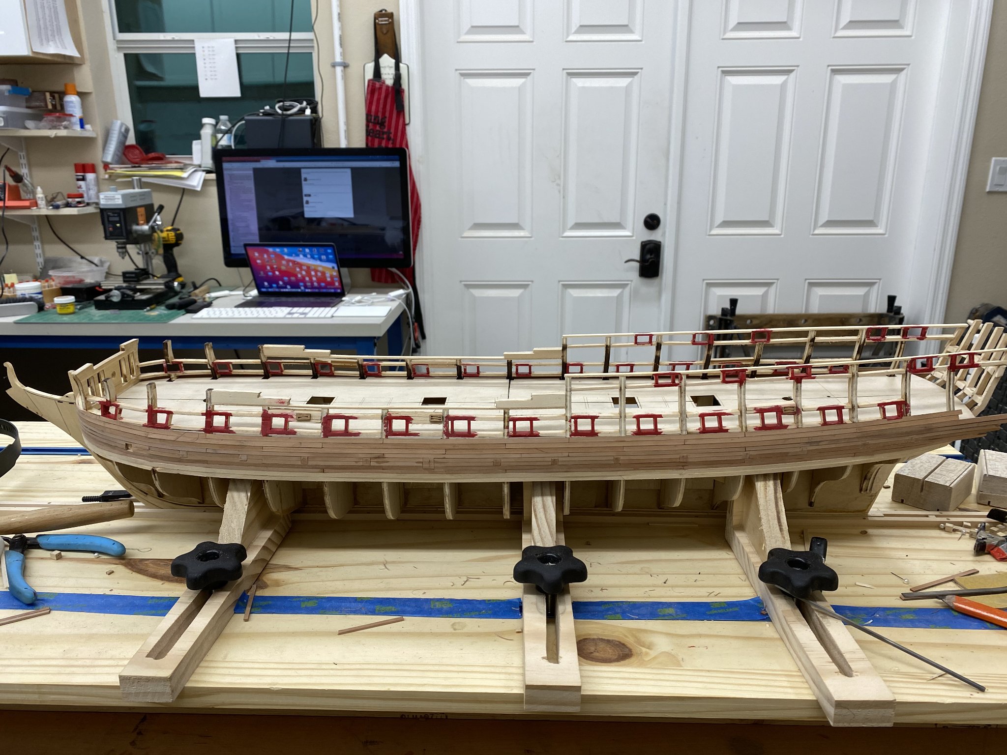
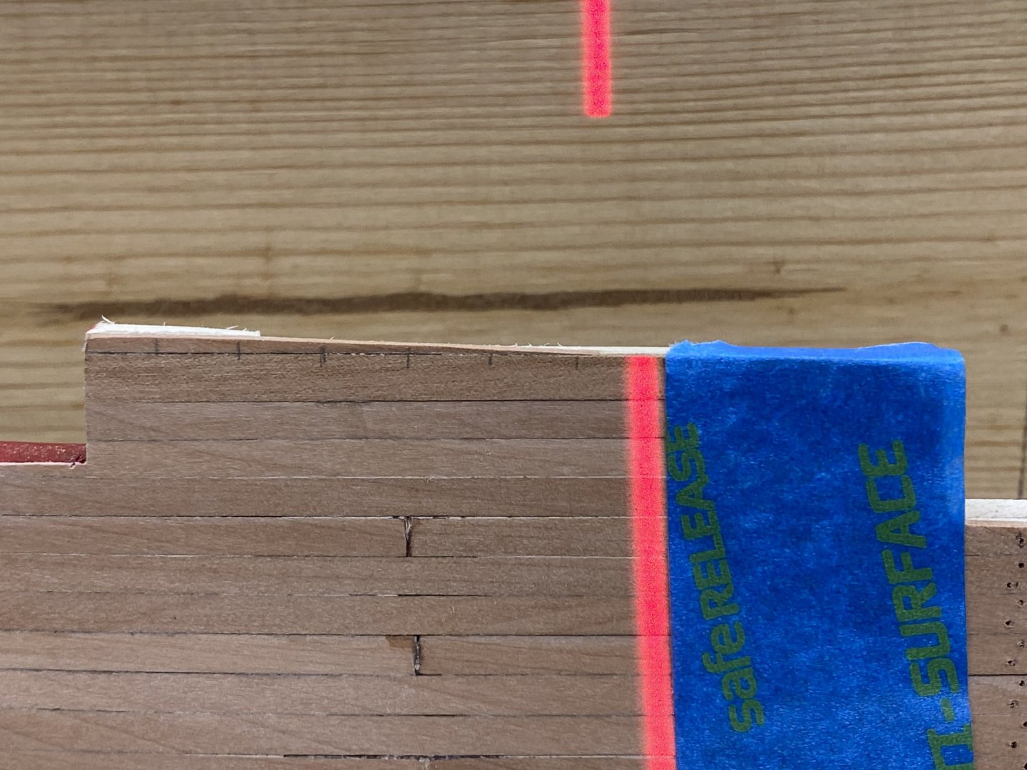
After almost four weeks of suffering from "model fatigue" I finally got back to the Confederacy. Plus I had to take advantage of the "nice" (compared to the summer) weather to get some outside projects done. So several hundred square feet of pavers, two outdoor swing assemblies and a couple of cans of paint later I find that working on the model has much more appeal than it had a month ago. When I left off I was almost done with the upper bulkwarkm planking on the out hull. So the first step is to get the last dozen or so pieces of bulwark planking installed. I was unable to duplicate to instructions edict to use the 15th stake of planking as the top of the quarterdeck bulwark. I planked above that (two planks in some areas and the marked where the top of the gun ports should be (10mm up from the sill) and then faired a line through those marks for the top of the bulwarks. Clearly there is not a single row of planking that marks the top but... I sanded both sides with 100 grit paper and wiped it down with paint thinner to see what it looked like and here it is: The blue tape was to protect the stem while sanding the bow planking. Next with the 220 grit and then a thin coat of Wipe-on-Poly to help define the plank rows while I struggle with the "Fancy" molding. I noted from Bossman's log that the lower row of molding has to be removed in the way of the channels so I think maybe I will wait and install that at the same time as the channels. I looked ahead in the instructions and do not see any "fatal flaw" in waiting. But then the fatal flaws you don't see are the ones you have to deal with... I am "on the fence" on the treenails on the hull. If I do it at all I will only do the starboard side so If I don't like the "look" I can turn it around in the display case.
- 370 replies
-
- 6
-
-
- Model Shipways
- Confederacy
- (and 1 more)
-
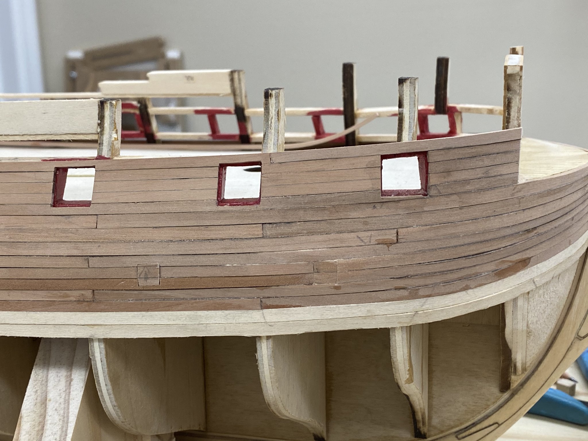
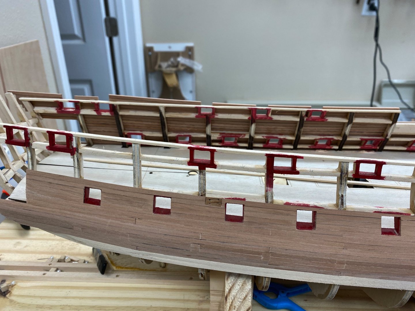
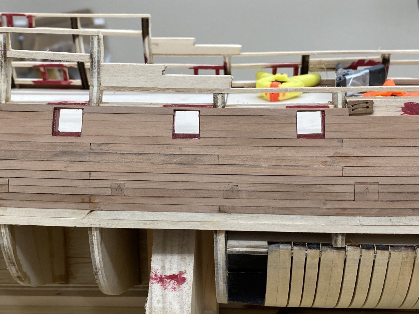
So I have continued planking the port side to the top of the bulwak and around the quarterdeck gun ports. The instructions say that the 15th plank above the wales should form the top of the quarterdeck bulwarks. That is where I would have stopped but it was not tall enough at least at the forward ports to get the 10mm height at the gun ports. So I added an additional plank above the first three gun ports. Here is what it looks like. Clearly some trimming is going to be required. Here is what it looks like from the other side to get a feel for how far above the lintels the planks extend. The instructions say that another 1/16" lintel strip should be added if the 15th plank needs support above the single lintel that is already there. That is the case here as the two after ports have 15 planks. However, the three forward ports have 16 planks because 15 will not clear the existing single lintel. I am considering my options. Clearly I will not have a single plank that defines the top of the quarterdeck bulwarks. There will be partial planks at the top somewhere. This also makes the step at the quarterdeck 17mm high instead of the 13mm that is shown in the plans. I am moving on to planking the stbd side and will see how things work out on that side before deciding what to do here. The worst thing would be to have the sides different heights.

- 370 replies
-
- 3
-
-
- Model Shipways
- Confederacy
- (and 1 more)
-
You are welcome Pogy I have looked at many build logs and added tools and techniques that I have found there to my "toolbox" so I do not claim anything in my build log as "original".
- 370 replies
-
- 1
-

-
- Model Shipways
- Confederacy
- (and 1 more)
-
Port side complete to top of gun ports (and I added the missing sweep port door at the bow) and the first 1/8" plank to reach the stern frame has been added. Working on the port side to complete the planking above the wales.


- 370 replies
-
- 3
-
-
- Model Shipways
- Confederacy
- (and 1 more)
-
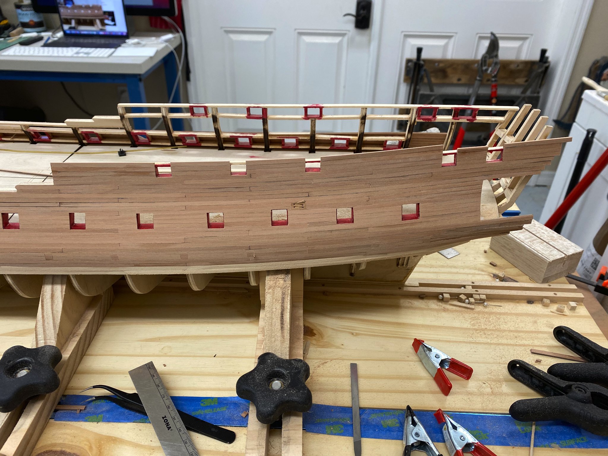
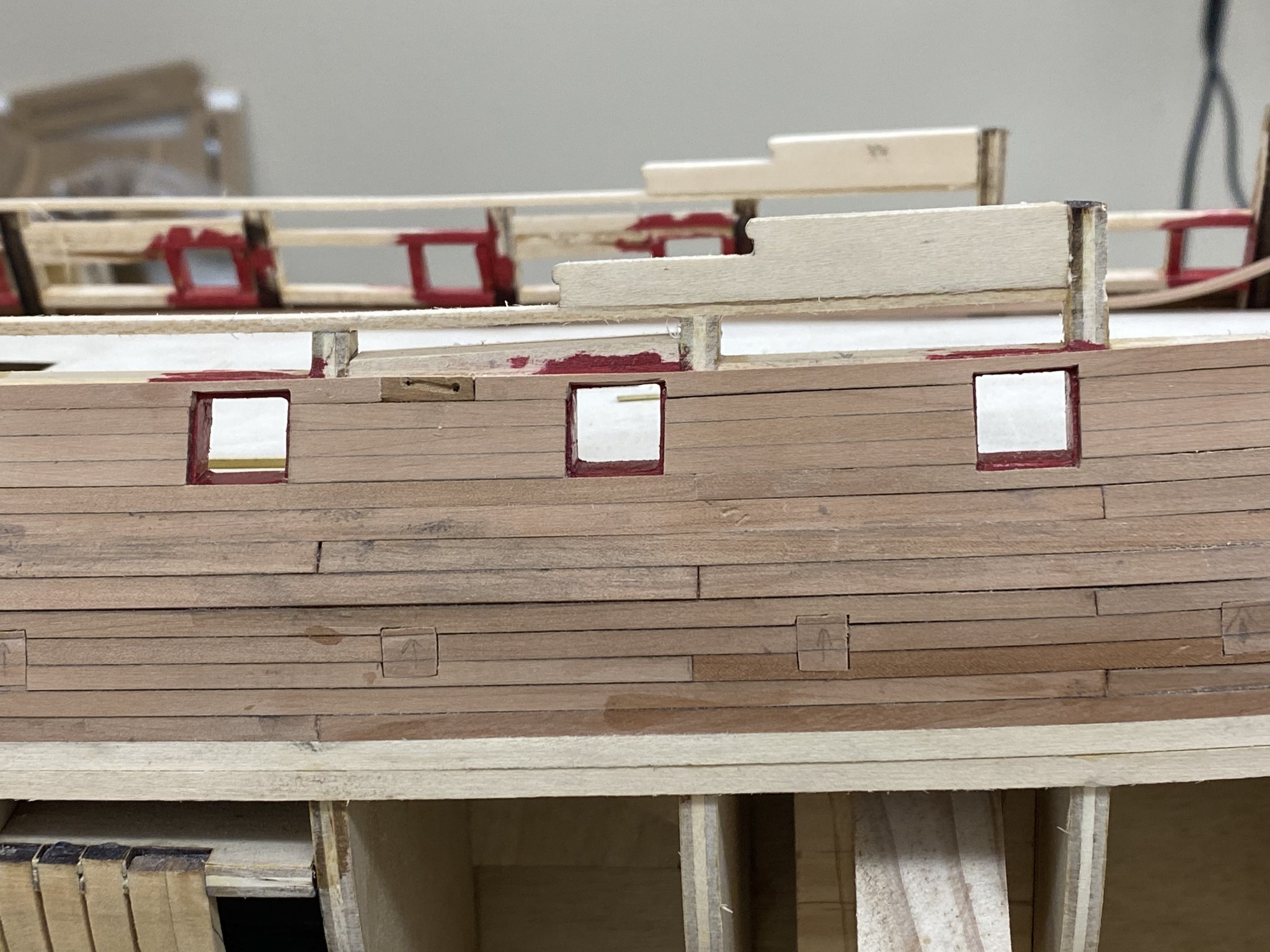
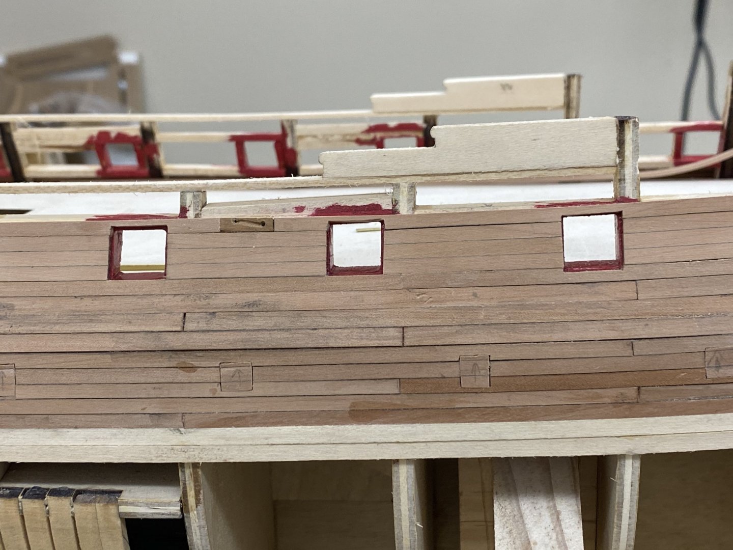
Now that yesterday's "scare" over the number of planks for the quarter galleys has been put to bed as a failure to read the instructions and count to 10-, I finished off the stbd side planking to the tops of the gun ports. So here are the 14 starboard side gun ports. I am going to move to the port side and get it completed to this point before I add additional planking above the gun ports.

- 370 replies
-
- 2
-
-
- Model Shipways
- Confederacy
- (and 1 more)
-
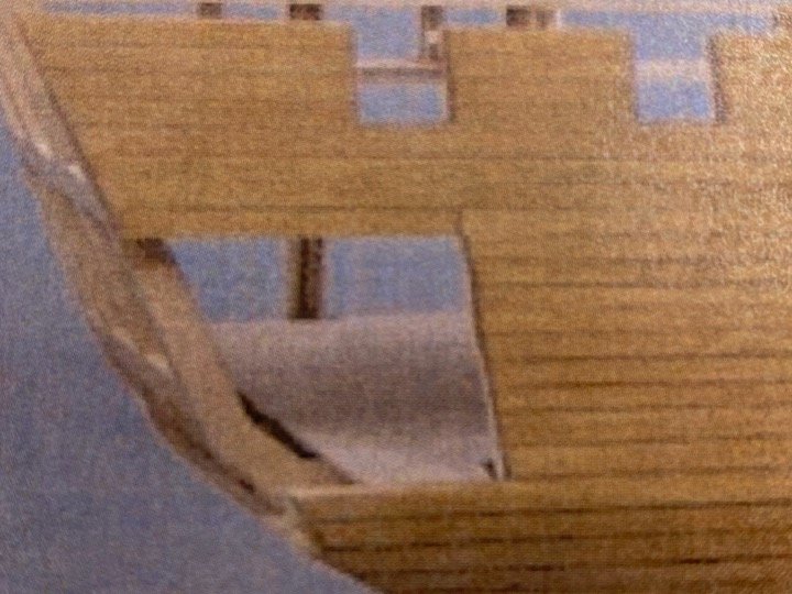
After carefully rereading the instructions and looking at the below picture I think the issue was mine. If I carefully count the rows of planking in the below picture, which I copied from page 37 of the instructions I count 10 rows of planking starting with the first row that does not extend to the stern. That is what I will have if I keep going . Sorry for the mistake and thanks for the quick responses.
- 370 replies
-
- 1
-
-
- Model Shipways
- Confederacy
- (and 1 more)
-
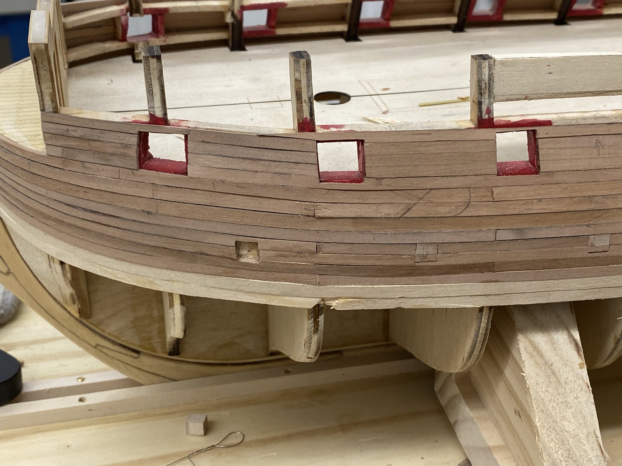
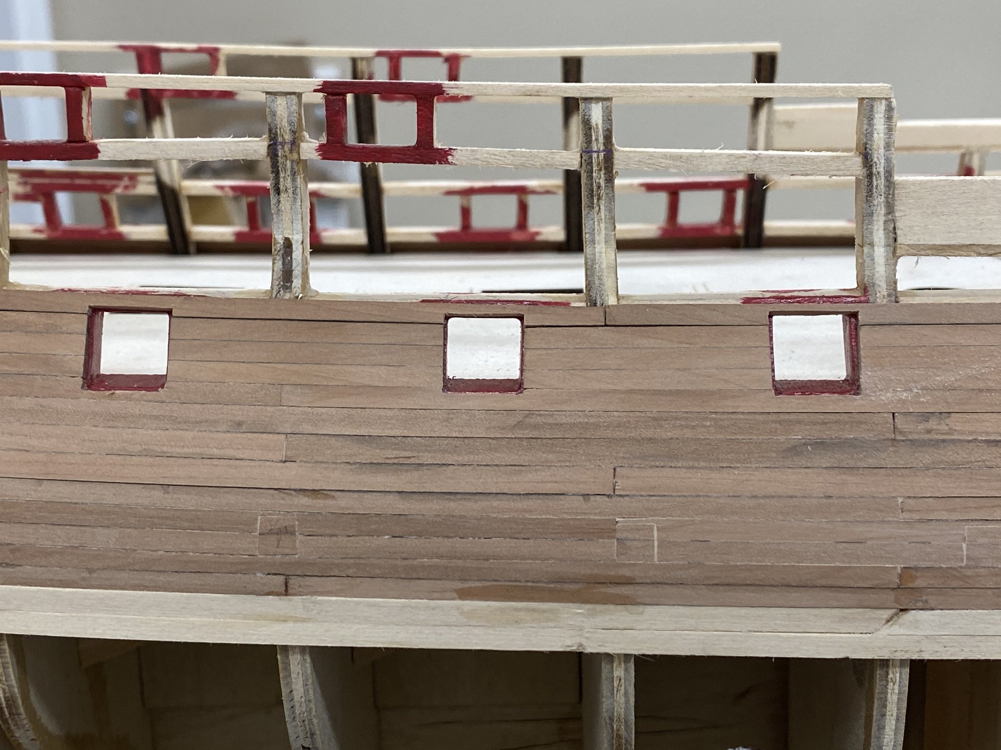
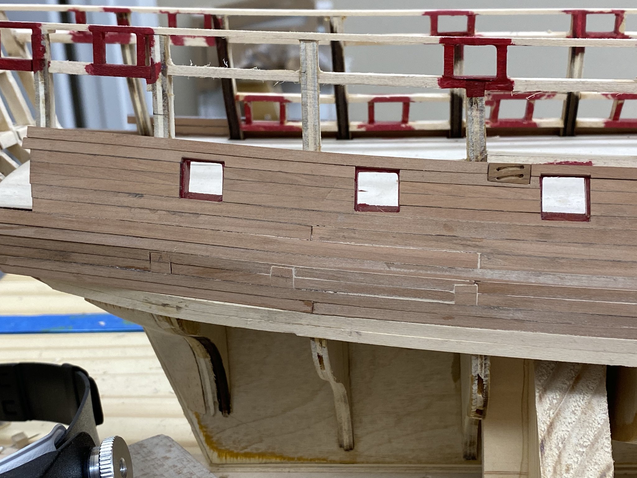
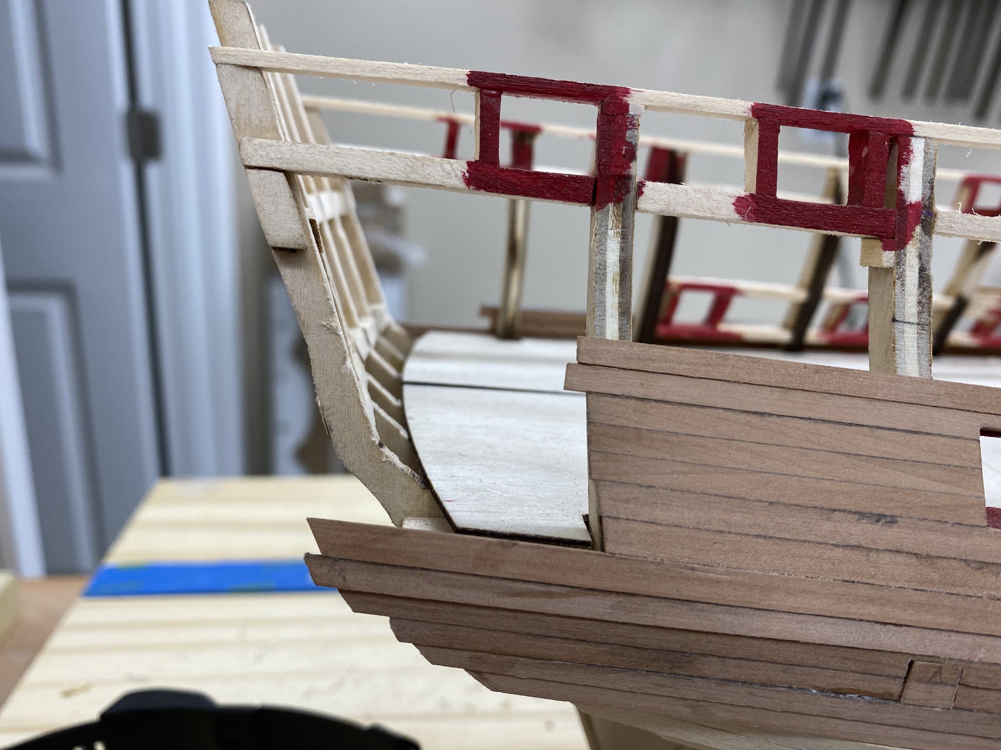
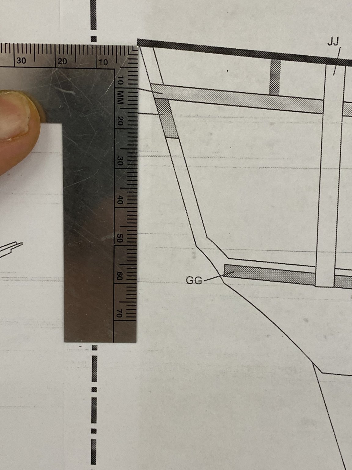
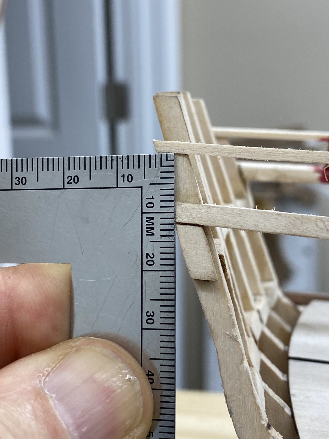
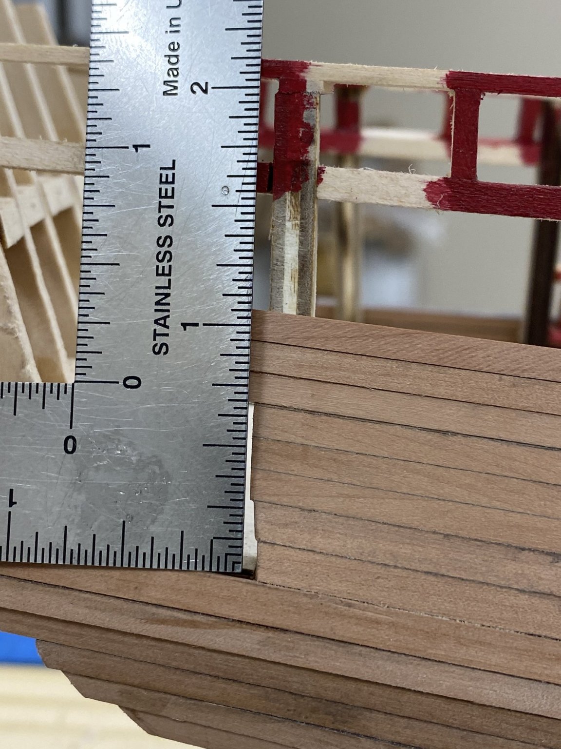
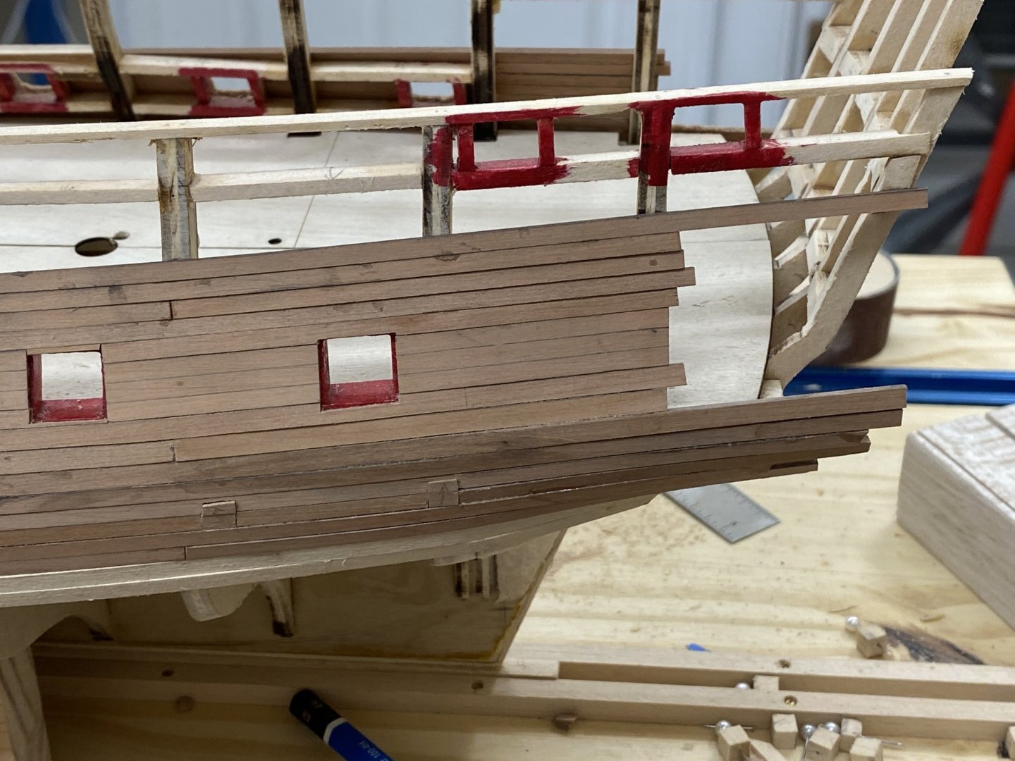
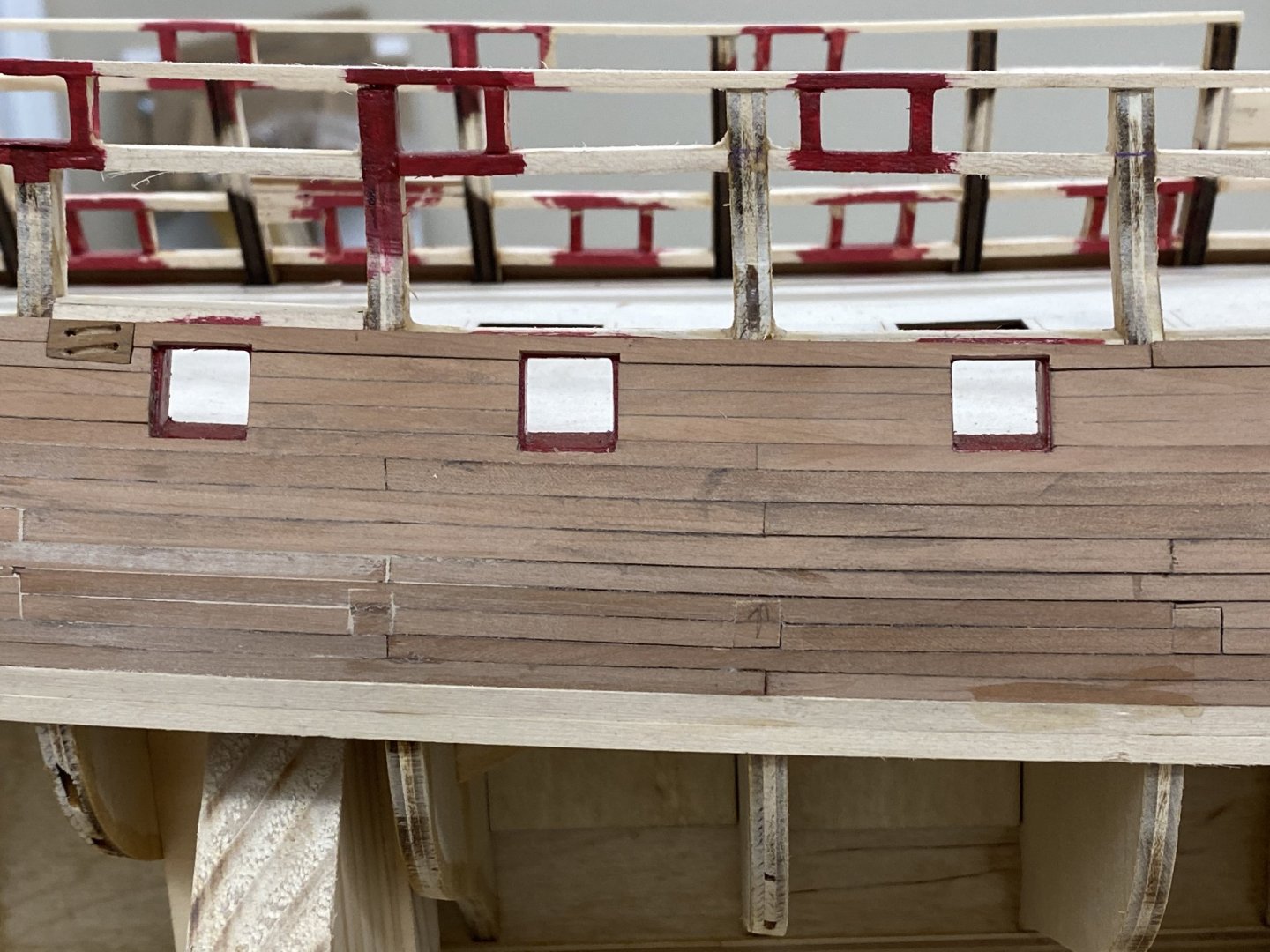
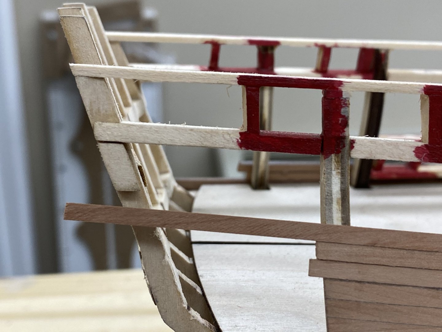
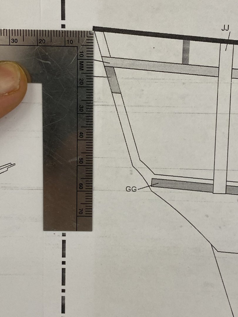
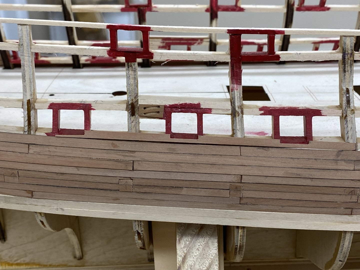
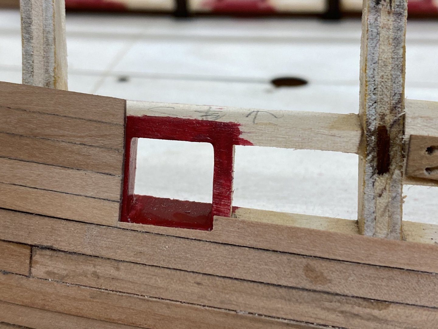
I got eight of the stbd side gun ports framed in without additional "drama". Here they are: However I have run into an issue that I am not sure how to solve. According to the instructions, the eighth plank up from the uppers wales (the sixth 1/8" plank) should extend to the stern frame (instead of stopping at Bulkhead J J) to form the top of the quarter gallery opening. It further states that this plank should "flow nicely onto the small stern piece ZZ". Sounds pretty straightforward. Here is what my quarter gallery area looks like: As I count it there are seven planks (2 X 5/32" and 5 X 1/8") now in place above the wales. The piece ZZ referred to in the instructions is visible on the stern frame. If I place another plank on the bulwark it looks like this: It appears I am probably two planks short of hitting the ZZ piece with this "eighth" plank. I looked at the drawing to see if I somehow had misplaced ZZ. The drawing shows the bottom of ZZ to be about 22mm below the top of the stern frame. The ZZ on the starboard side appears to be no more than 1/2 a mm above where it should be per the drawing, i.e. 21.5 mm below the top of the stern frame. The eight planks (2 5/32" and 6 1/8") should be 1 1/16" tall. So I measured the planking thinking (since I milled it myself) that maybe I was off on the plank widths (although I considered this unlikely since I used the thickness sander to set the plank width and I have great confidence in the Byrnes thickness sander's ability to reliably deliver the set thickness). So I measured the height of the planking And got the required 1 1/16". I am at a loss for how to proceed from here. Options (at least to me) include: 1. Add an extension to the ZZ piece to intersect the eighth plank. 2. Add a eighth and ninth plank to the bulwark terminating as the ones below and extend the tenth to piece ZZ 3. ?? I am proceeding with planking the gun ports moving forward (and then the port side) while I try and decide what to do about this problem.


- 370 replies
-
- 4
-
-
- Model Shipways
- Confederacy
- (and 1 more)
-
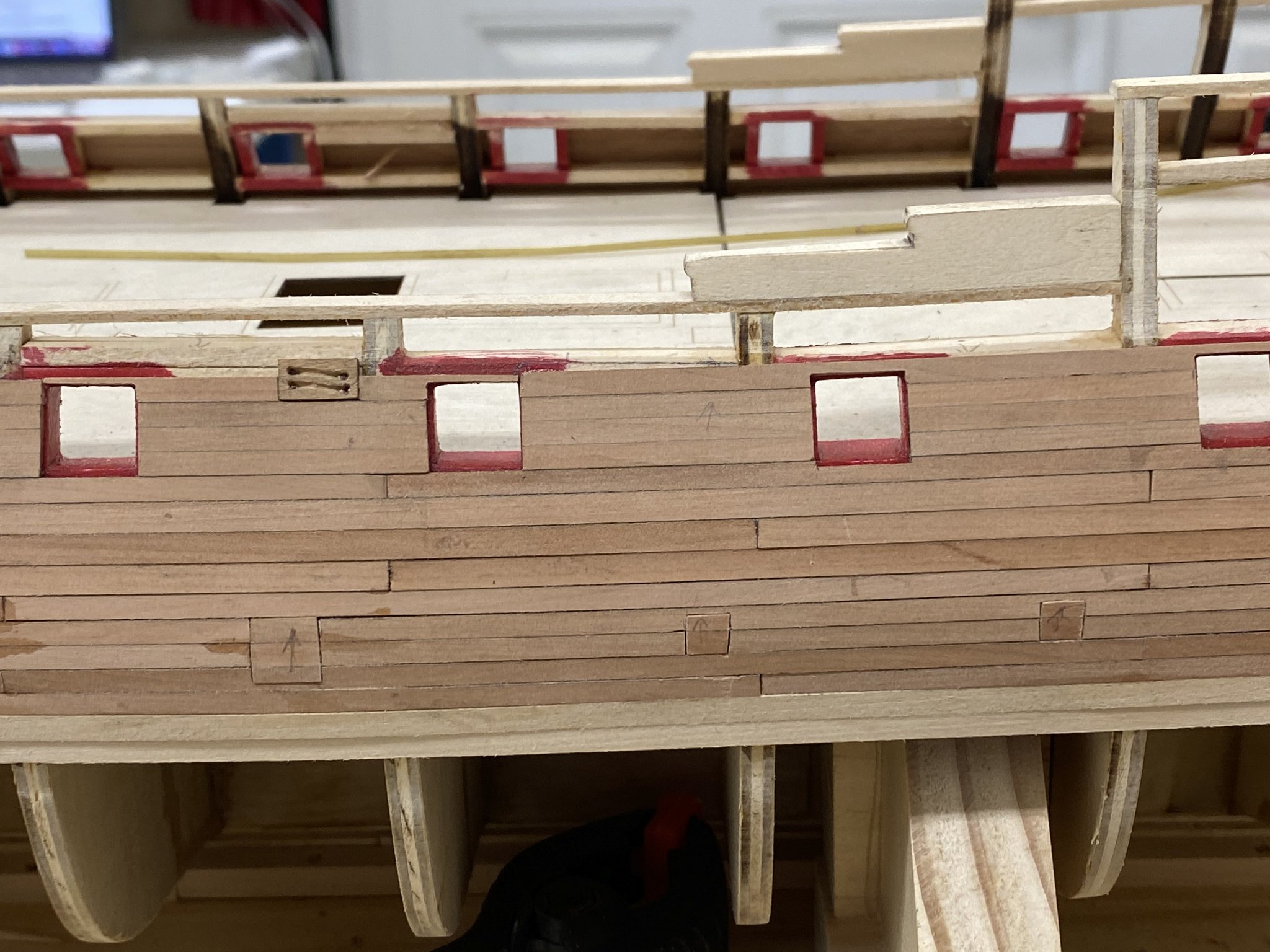
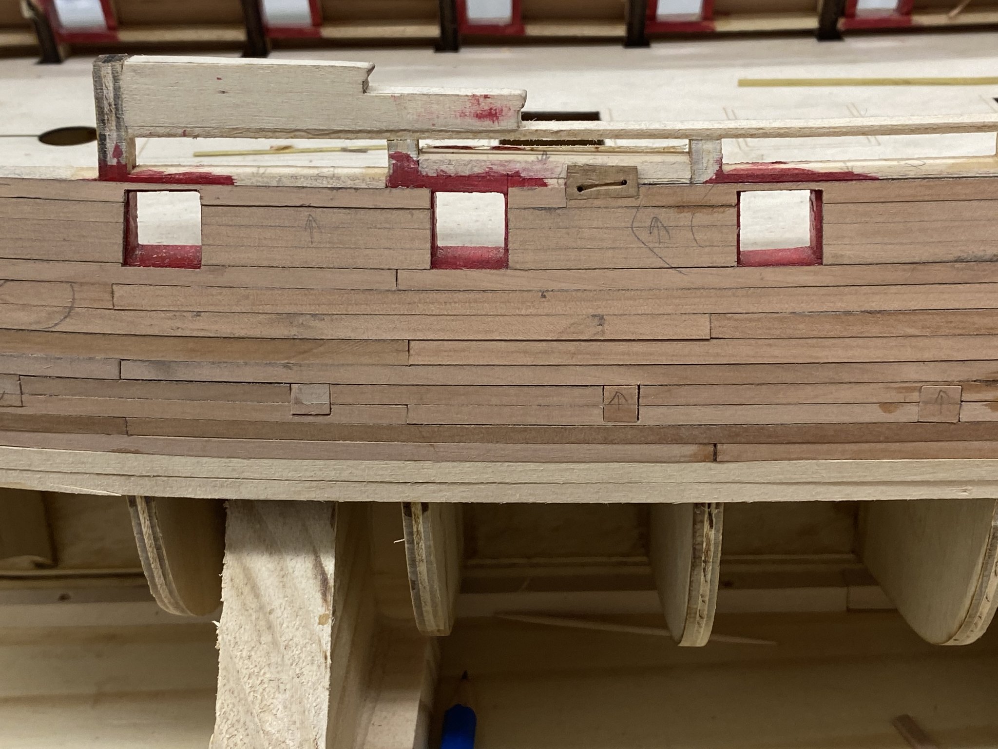
After experiencing a good deal of difficulty getting two bulwark planks to line up vertically for the sweep ports I decided I needed to try something else for the gun ports. So I thought that if I could use the disk sander to get the edges of 3-4 planks straight and at the correct angle based on the port geometry I might be able to come closer to the desired appearance. So I started by milling some additional 1/8" X 1/16" Swiss pear planks being careful to keep all the planks from a given blank together (eventually I used colored pencils to color the end of each blank so I could tell which planks came from a particular blank). That was fine as far as it went but I noticed that while cutting out the planks a certain amount of scaring was occurring on what would be the face of the plank. Because of the configuration of the blanks I have I was thickness sanding them to 1/8" thick then cutting off 1/16" "slices" to form the planks. Having the micrometer adjustment on the Byrnes table saw came in really handy for getting the planks close to 1/16" thick. Next time I will make them a bit thicker - see below. So with the new planks all from the same blank I edge glued four of them together to form what will become the planking between the gun ports. Here is one of the edge glued "super planks". Next time I will make the super plank thicker than the required 1/16" and use the fine sandpaper in the thickness sander to get it to 1/16" with a "cleaner" finish than I get with the table saw, even using a 100 tooth blade. I decided to start at the stern to avoid the curved section at the bow which may require a different solution. First I needed to define the bottom of the gun port so I carefully cut and sanded the piece below which forms the bottom of three gun ports. The after most port bottom is formed by the top of the last 5/32" plank in the upper wales. It is not glued in yet. It takes a certain amount of patience and a good set of fine files and sharp Xacto blades to keep all three port opening where they belong. I will admit it took me three tries to get all three of them in acceptable shape on a single piece of planking. I cut a piece of the super plank and carefully sanded one end flat (90 degrees) then measured and incrementally using the disk sander with 320 grit paper sanded the edge so it was parallel to the port side (the picture shows a super plank five planks wide - I have since moved to four wide although in many cases three wide would be enough). Here is the super plank placed aft of and abutting the bottom piece. Now as they say the "tricky part". With the forward edge defined, now use the disk sander to get the aft edge parallel to and the correct length to fit the next port aft (which is the after most port). Fortunately the disk sander can take off (with a little practice) a very small amount (I estimate .010") at a time. So here is the super plank now forming the bulwark between the two after most gun ports. You can see the very small amount that was removed from the top wales plank to accommodate the gun port rabbet, although I will be the first to admit that 1/64" is pretty small and mine are probably closer to 1/32". Another super plank is cut and sanded (although now the after end is not critical since it can extend aft of bulkhead JJ and be trimmed flush later. I did have to fashion the analog of the bottom piece for the top to finish off the after most port but I believe that the rabbet here is not as critical since the gun port cover will be attached here and viewing the top of the gun port rabbet would be quite a chore should someone decide it was important. So here is the "finished" after most gun port planking. Hopefully the rest (until we get to the forward most or two) will follow in the same fashion and I will get better at carving the notches for the upper and lower pieces. At least the sides are straight (for three planks anyway) and hopefully parallel (more or less) to the port sides.
- 370 replies
-
- 4
-
-
- Model Shipways
- Confederacy
- (and 1 more)
-
Pogy - you are most welcome. Anything for a sewer pipe sailor. Check out my build log of the Charles P. Notman; another schooner, this one with four masts but a similar jib arrangement. Thanks Mark.
- 166 replies
-
- 1
-

-
- fannie a gorham
- finished
- (and 1 more)
-
Thanks Mark.
-
Bruce, I decided to build the guns and ship's boats before starting the hull so you can see what and how I handled the gun carriage blocks here: Also Bossman has some detail, on how to make the small hooks if you decide to go that route. If you have any specific questions I will be happy to provide what I can. Gary
-
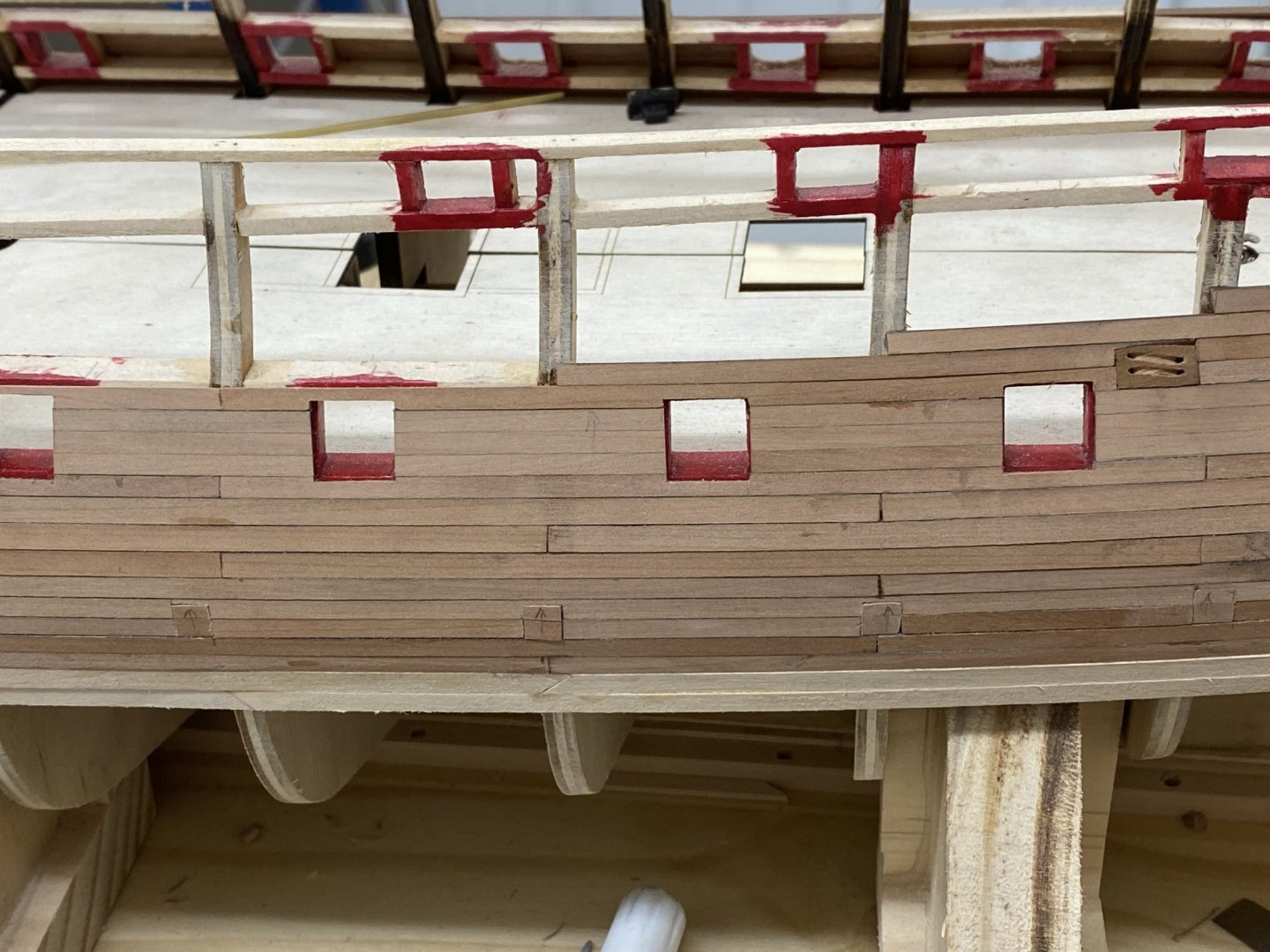
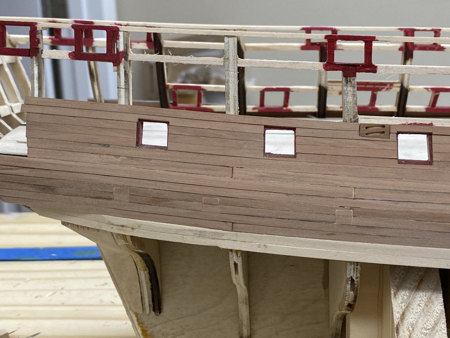
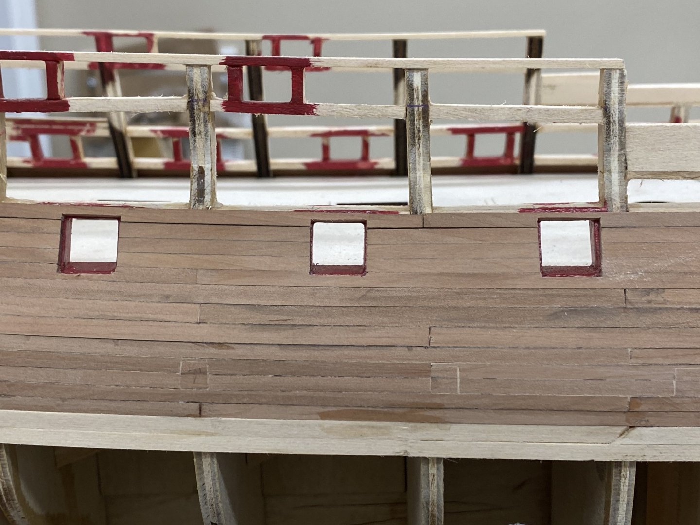
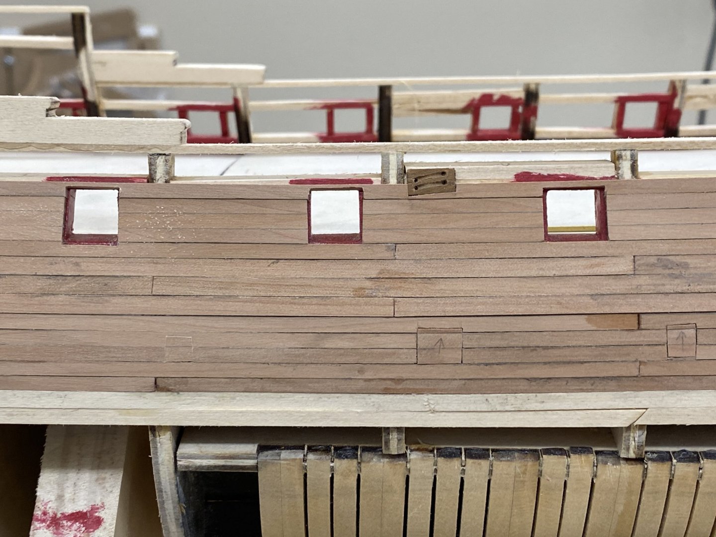
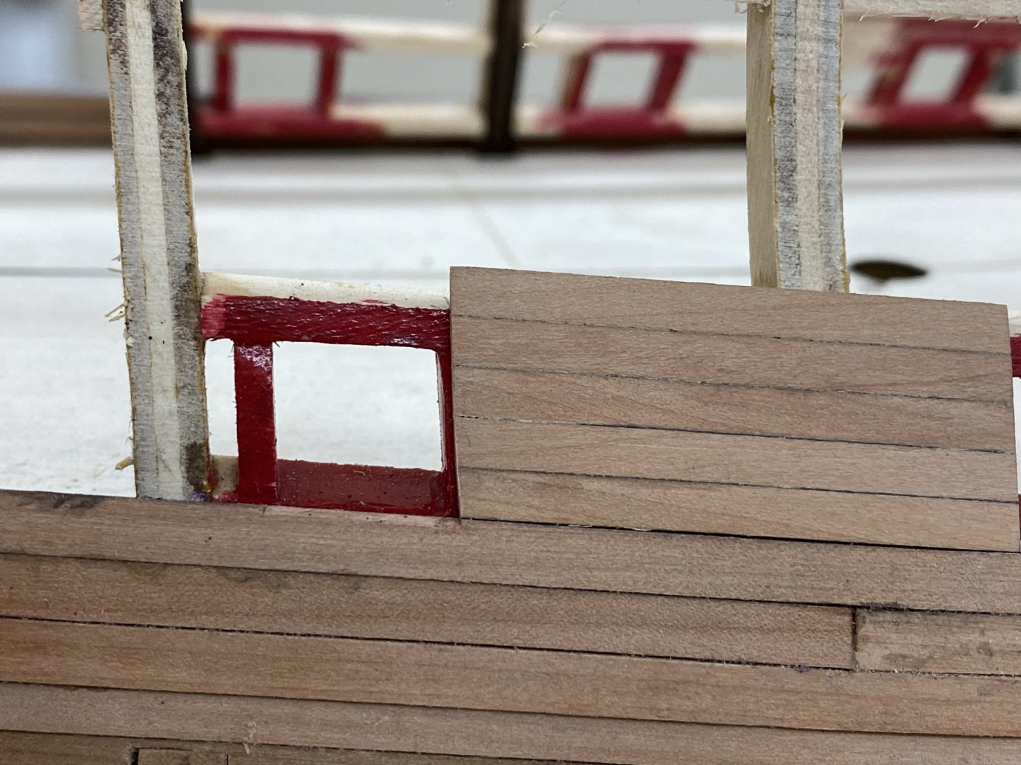
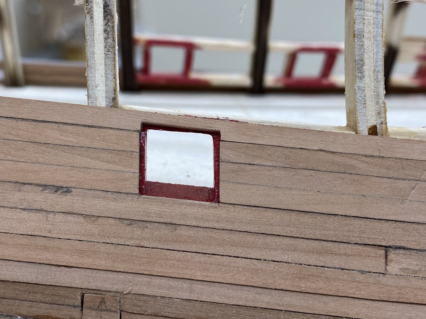
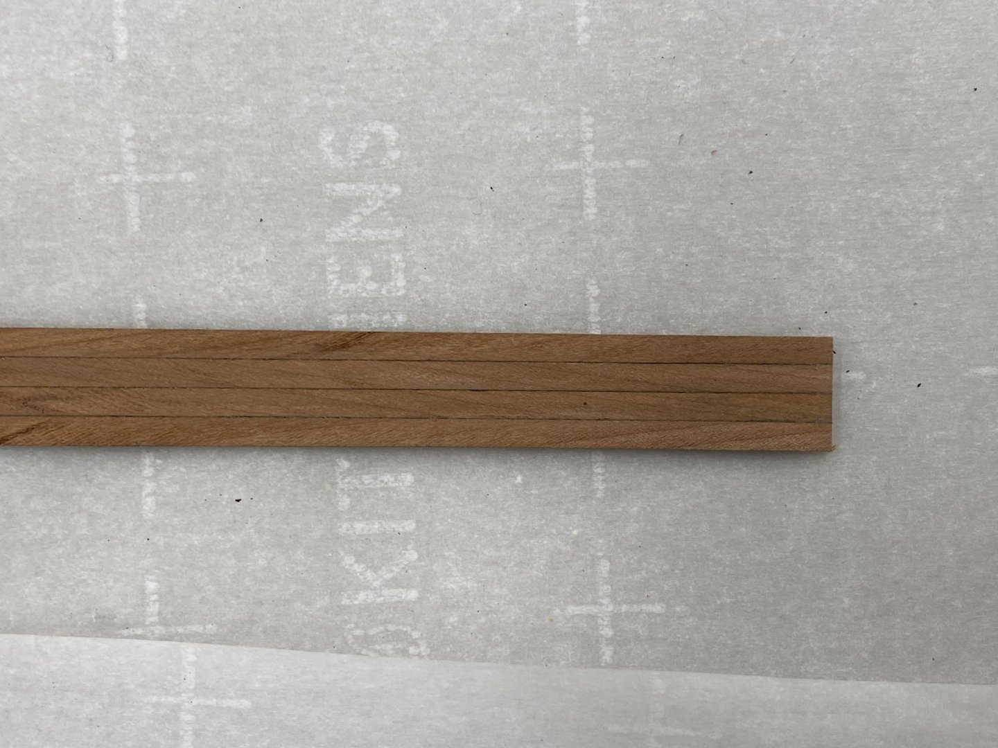
While rereading the instructions for completing the exterior bulwark planking I noticed that I completed the sweep port doors incorrectly. The instructions say to use a single piece of 1/4" X 1/16" to fashion the door. I pieced together two 1/8 X 1/16 pieces of the hull planking to make the sweep port doors. It will be awhile (until I get the rest of the bulwarks planked) until I get a good idea of how this looks. Hopefully I did a good enough job matching the seam lines so it does not actually draw attention to the sweep port doors. I am not sure they should be a focal point on the hull. Anyway except for one sweep port door I have the port side completed to the same point at the starboard. Ten rows of planking 5 of 1/8" and 5 of 5/32". Plan is to "keep going" to get the lower wales and bulwarks completed alternating from side to side following Bossman's example.

- 370 replies
-
- 3
-
-
- Model Shipways
- Confederacy
- (and 1 more)
-
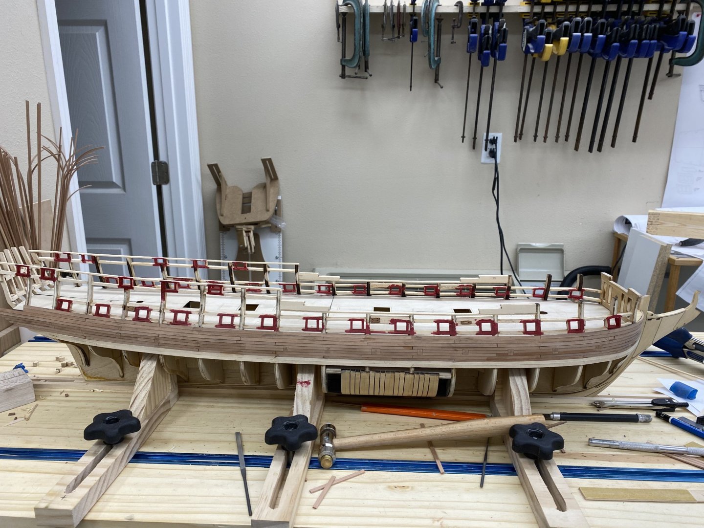
Sweep port covers on stbd side completed. Working the post side planking around the sweep ports and upper wales planking. Will work the gun port planking after both sides are complete to upper wales.
- 370 replies
-
- 3
-
-
- Model Shipways
- Confederacy
- (and 1 more)
-
Thanks Bossman. That is certainly my hope. Did you alternate sides or do one to the top of the bulwarks and then the other?