cdrusn89
-
Posts
1,940 -
Joined
-
Last visited
Content Type
Profiles
Forums
Gallery
Events
Everything posted by cdrusn89
-
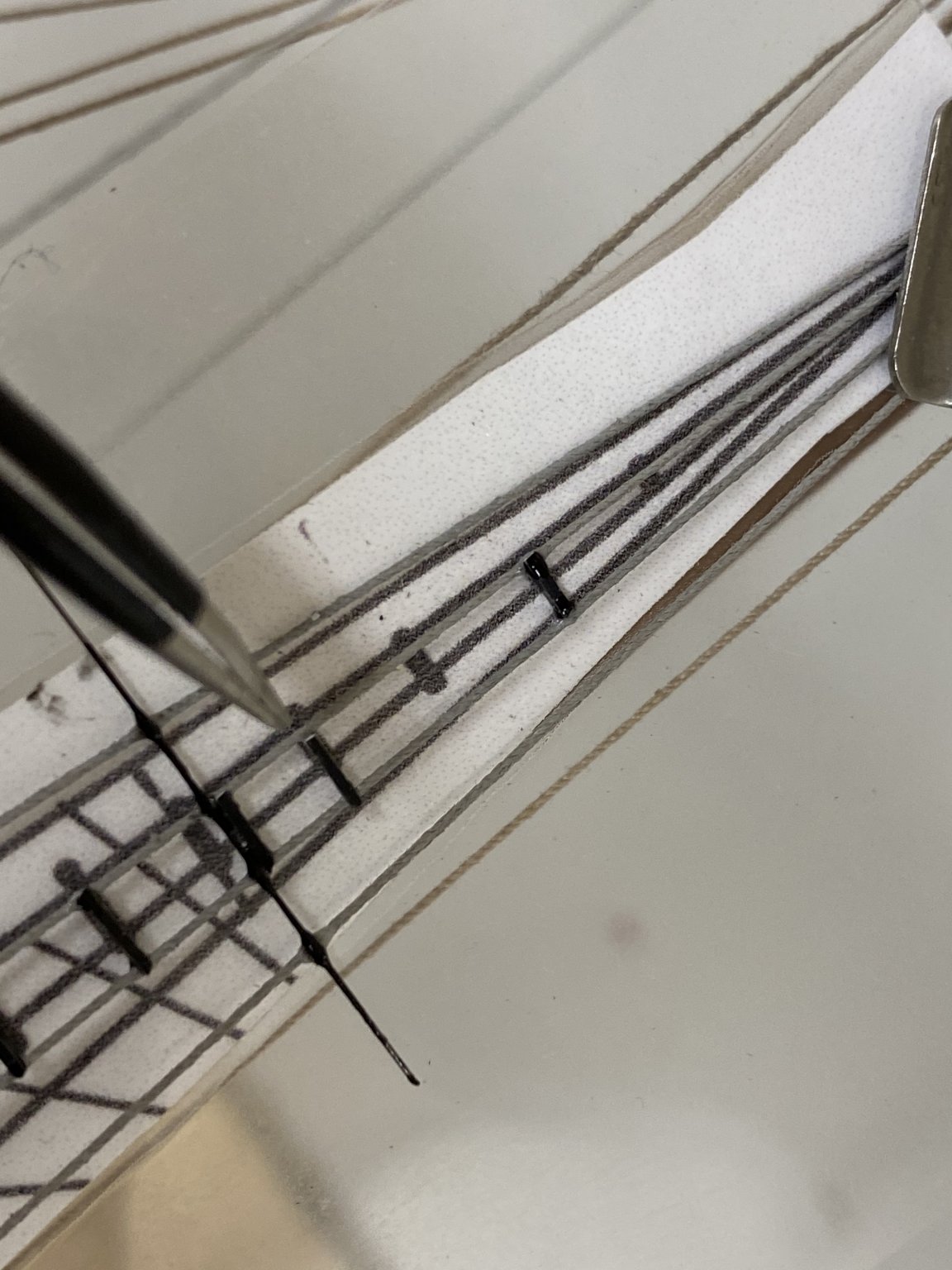
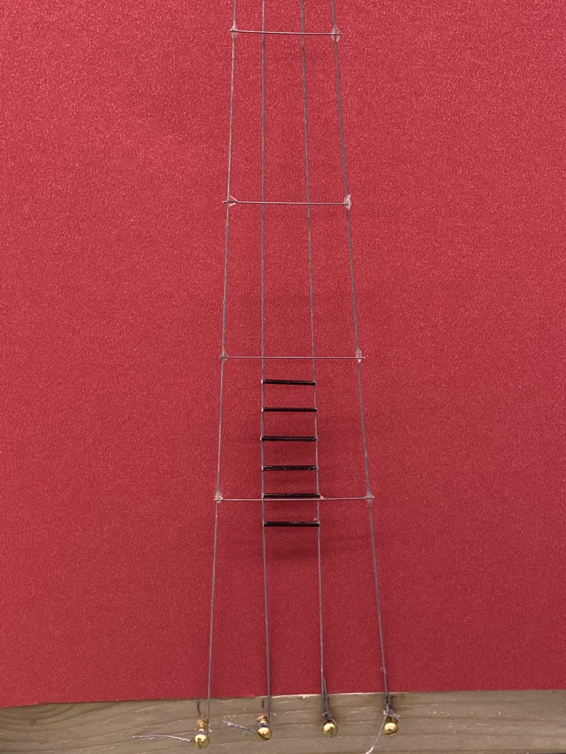
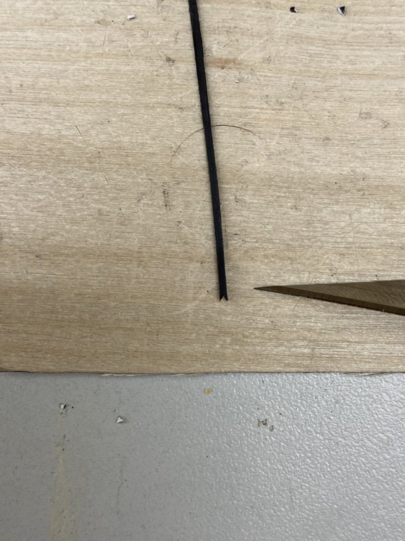
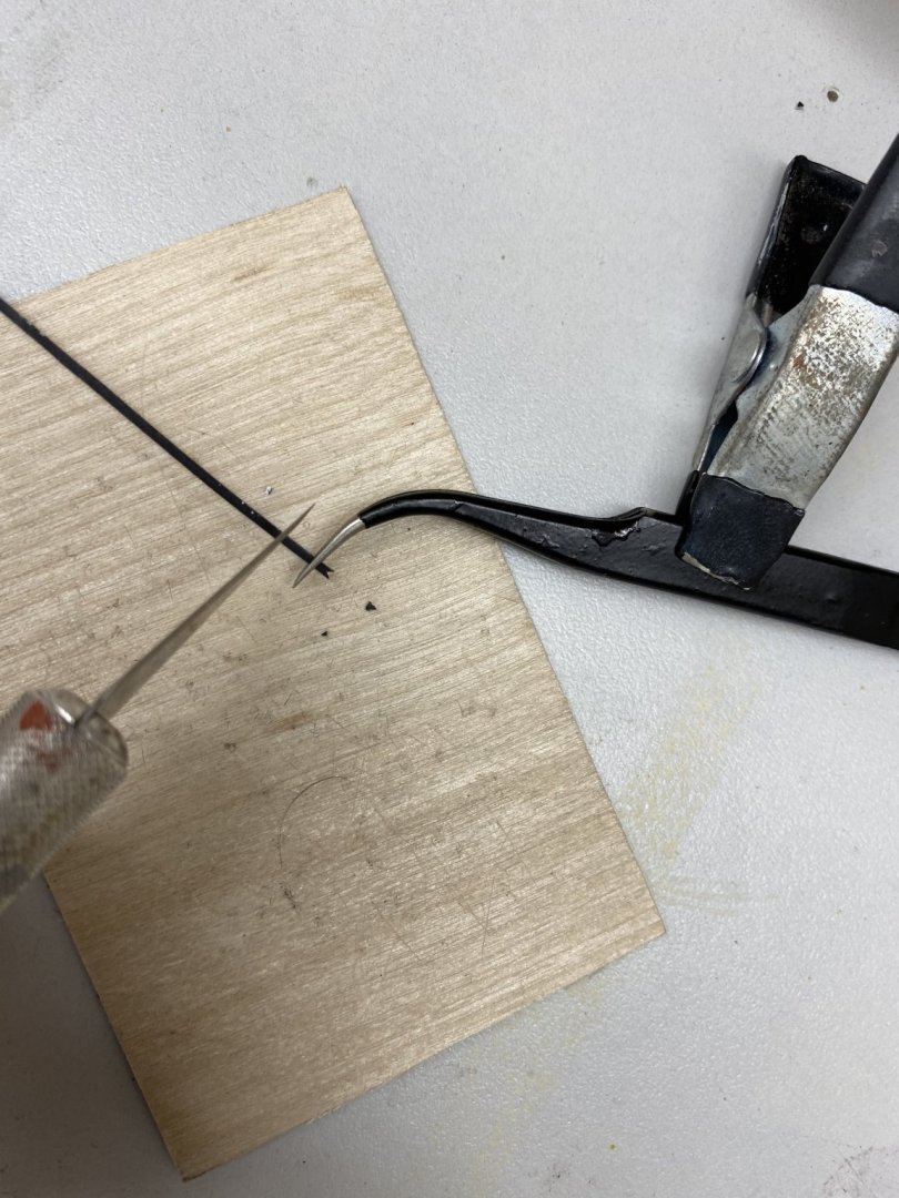
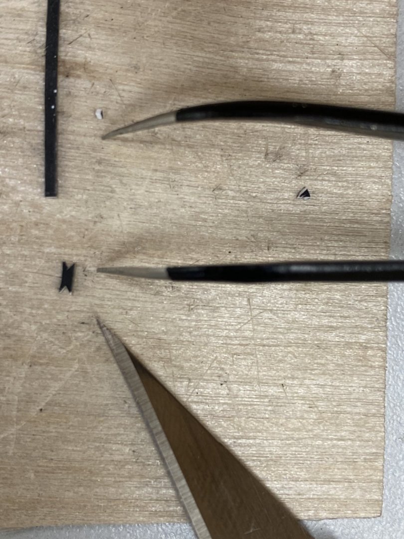
 Thanks bob. So I think I finally have the "plastic steps" process down. I just got the stbd side of the Mizzen done and it went a bit quicker than the Spanker. The first realization is that the model should be laying so that the shrouds are close to horizontal to the table. This makes it much easier to find the little pieces of plastic when they slip out of the tweezers or otherwise "come adrift". With the model upright there is just no telling where they might go except you can rest assured that generally they go where you can't find them. I start by cutting a small "V" in the end of the styrene strip which has been painted flat black Grab the styrene strip and engage the "V" on one of the shrouds at the location where it is to go and grab the strip at the other shroud with tweezers to mark how long the "step" needs to be. Cut the strip at the tweezers Cut a "V" in the new end Carefully (really) place the notched step between the shrouds at the desired location and twist to engage the "V's" Put a drop of glue (I have moved to medium CA for this - it is easier to control than the thin and sets fast enough so by the time you are done cutting the first "V" on the next one it has hardened enough so you won't dislodge it working the next one; although I have been doing every other step so I am not too close to the one I just did) on each end at the step/shroud junction. I use a sewing needle with half the eye cut off as a applicator for the CA and have a candle burning close by to burn off the excess CA on the applicator which I do after every step is glued. Here is the Stbd side of the Mizzen completed - only 6 more to go.

- 144 replies
-
- 4
-

-
- charles p notman
- finished
- (and 1 more)
-
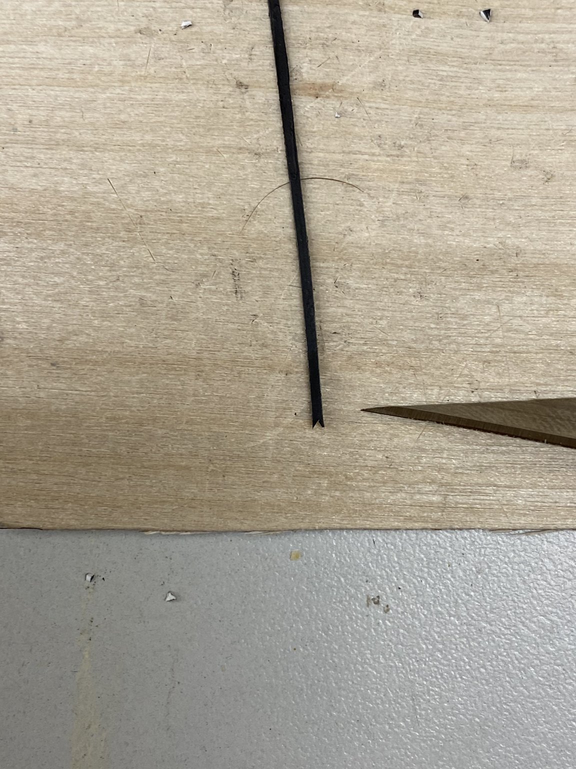
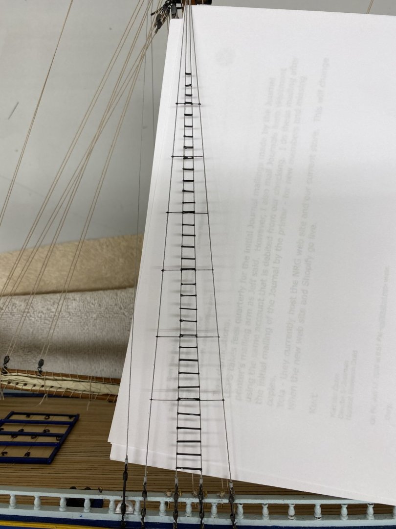
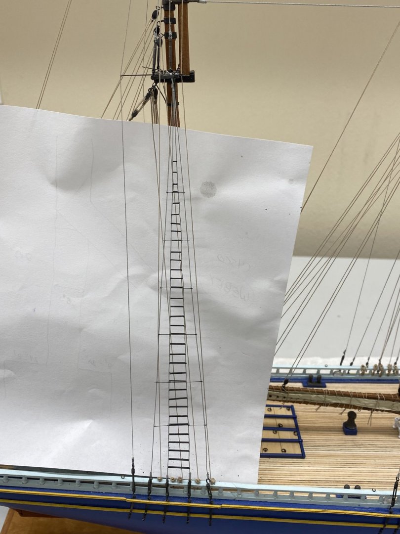
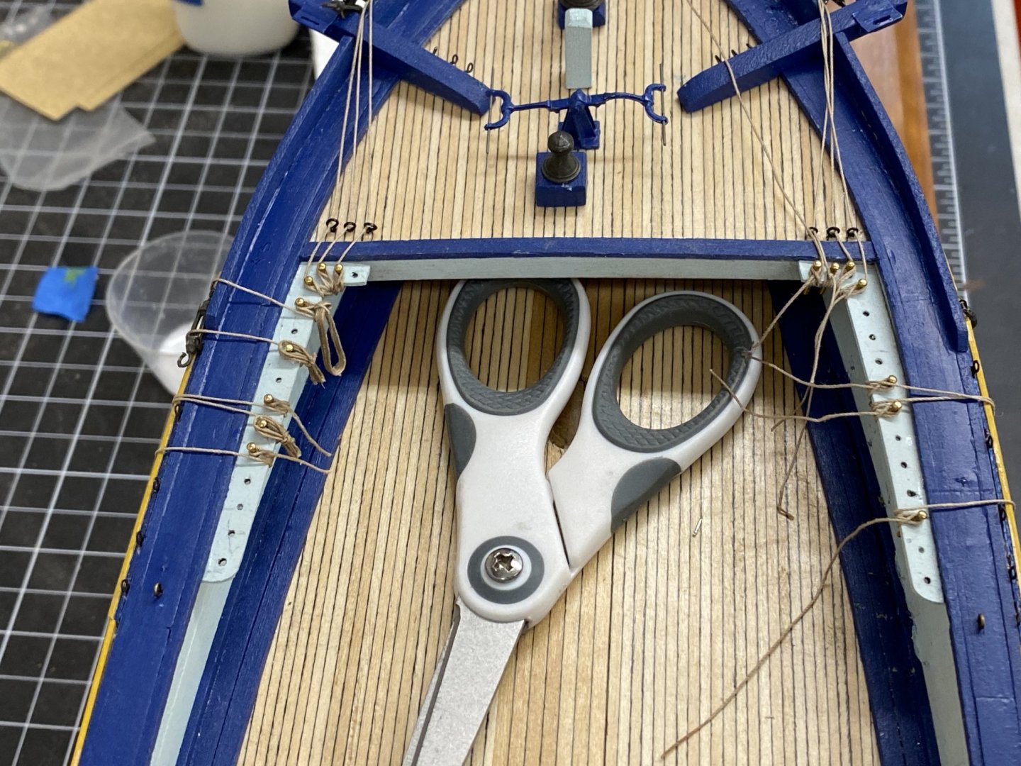
Thanks moab and Bob. I got one side of the Spanker "ratlines" completed. Not as straight and consistent as I would have liked but not a terrible job either. (Clearly I could have found a better background for the pictue - next time) Hopefully as I gain some more experience (this is my first attempt at this type of "ratlines") they will get better. When I did the test run I used Wendbond glue for both the music wire and the "steps". As I was trying to get the music wire installed (every fifth "ratline") I shifted to CA. It seemed to hold the wire and it did not leave as much residue as the Weldbond. It is not "sticky" like the Weldbond so I had to adapt my technique to account for this. I laid the hull almost horizontal so the music wire would hold its place (more or less) on the shrouds while I applied the CA. As I installed the steps I also used thin CA as it sets much faster and seems to grab the styrene satisfactorily. I thought (briefly) about using the styrene cement but that softens the styrene and does not set nearly as quickly as the thin CA. So 1/8th of this job was completed in a little over five hours. So only 35 more hours of dealing with tiny pieces of styrene and short pieces of music wire to go!

- 144 replies
-
- 4
-
-
- charles p notman
- finished
- (and 1 more)
-
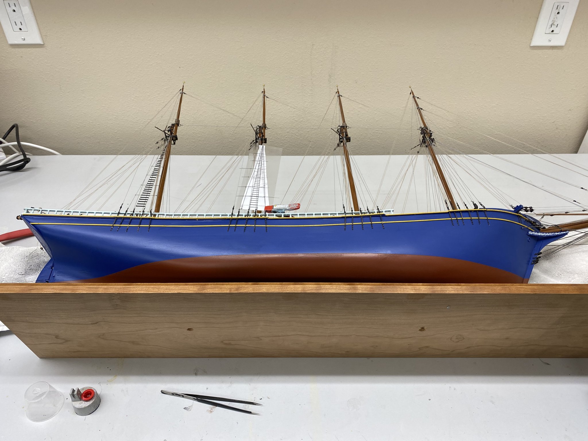
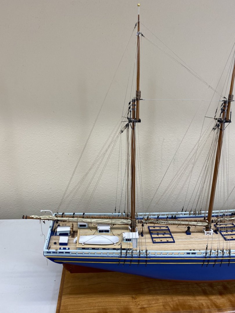
The rigging is mostly complete (anchors, boat davits and flag(s) are still to be added but not until... I get the "ratlines and steps" added. I decided to forgo the lazy jacks - more lines running vertically would detract from the looks IMHO (besides that would be another set of opportunities to break something else. That is the next step - I got the styrene strips painted, at least enough to get started and I am cutting the .010 piano wire into short pieces and painting them flat black in preparation for starting the first mast later today (or tomorrow) Here is how she looks at the moment. I will save the close up shots until she is truly "finished". But that is probably at least a week away as I suspect it will take most of a day to do one side of one mast based on the trial run I did earlier.

- 144 replies
-
- 8
-
-
- charles p notman
- finished
- (and 1 more)
-
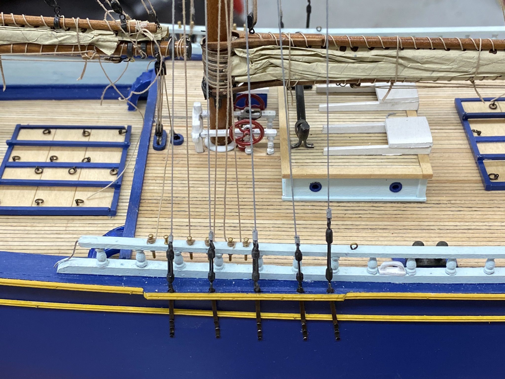
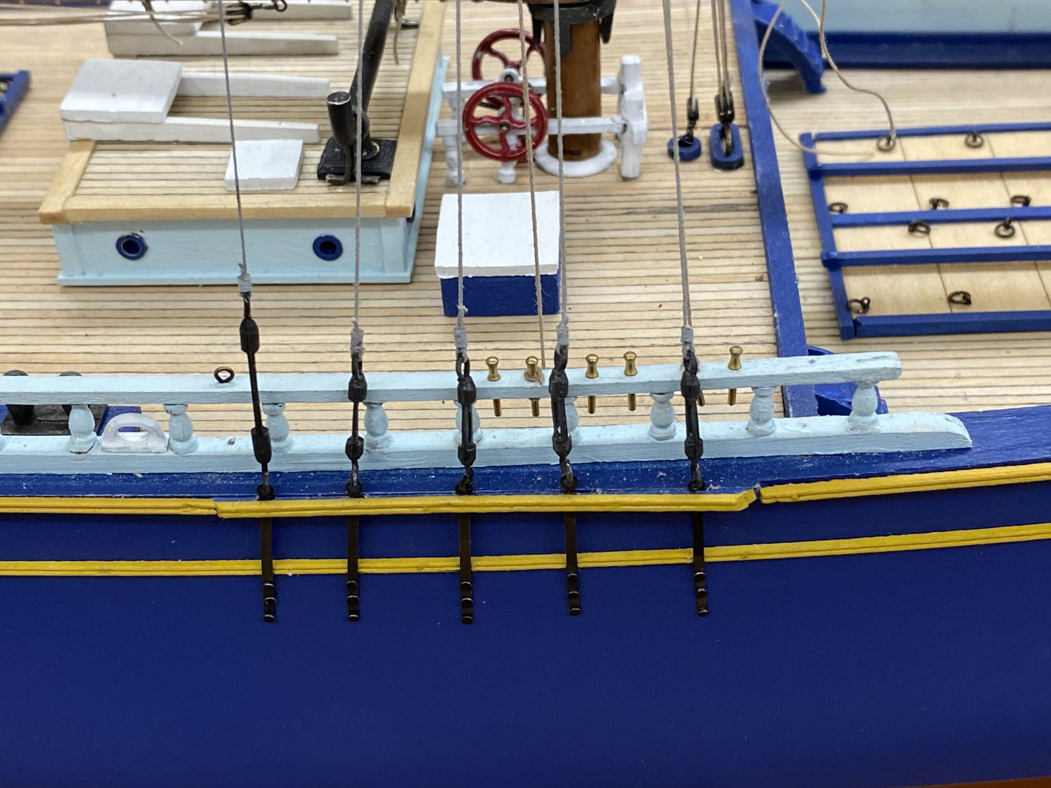
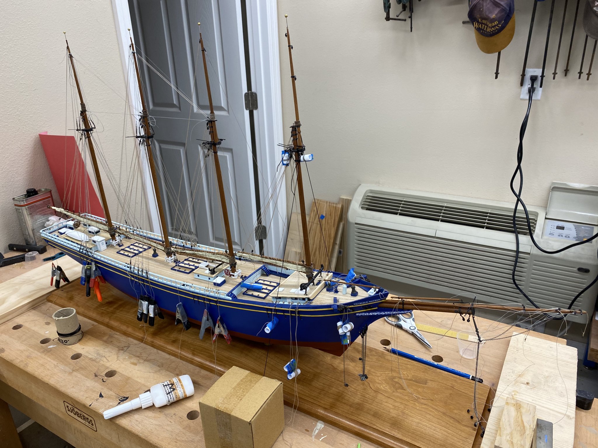
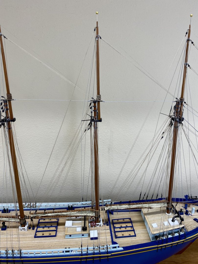
Spanker and main masts rigging has been glued down. I have to add the rope coils for the Main but after that it is on to the bowsprit. I have to tie off the many, many (16 actually if I counted them all) deadeyes that were used to rig the bowsprit/jib boom. Once those are secure, then it is on to the Foremast. Here are the Spanker and Main Mast lower shrouds and pin rails.
-
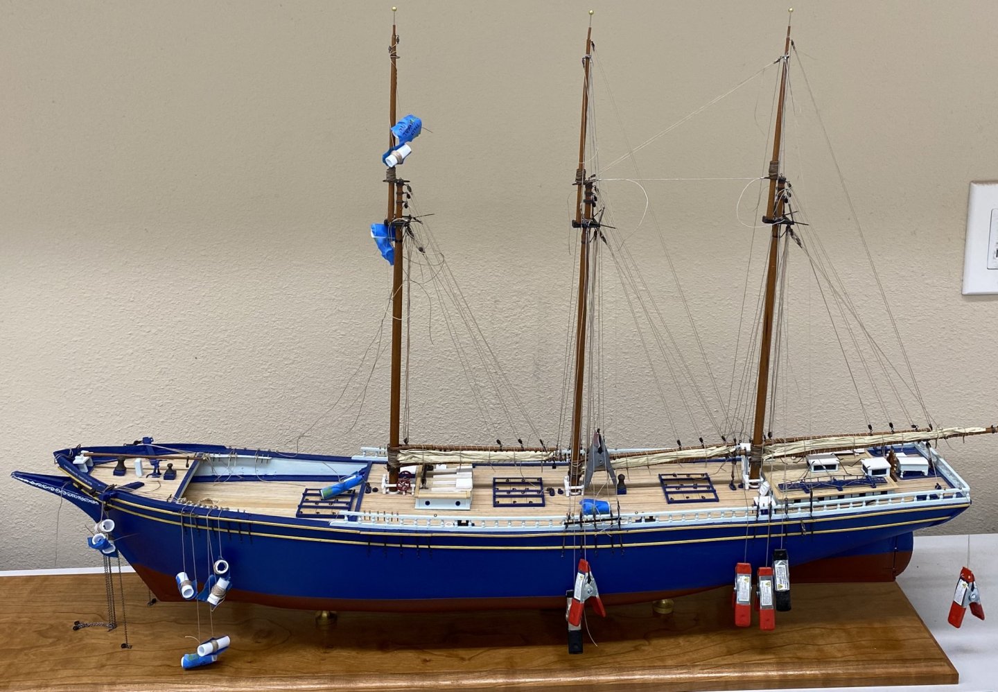
Stick a fork in the rigging and call it DONE (except for the anchors and boat davits). Everything is rigged but nothing is secured yet except the pin rail side of the running rigging at the Foremast - the belaying pin side of that was glued down before the forward deckhouse was installed. Although using the method Nic suggested (running the line through the pin rail hole and putting the pin in) would have worked as well. As it turned out I replaced all the halyard blocks on the Foremast anyway. Trying to thread the line through the tiny hole in the metal block becket while the block was hanging from the mast quickly fell onto the "too hard" pile. So here are the port side Mainmast and port and starboard Foremast standing rigging at the turnbuckles. Next I intend to start with the Spanker and work forward securing the running and standing rigging mast-by-mast while keeping everything aligned. Probably easier said than done but that is my plan. I am going to wait on the wooden battens and sheer poles until I have the "steps" installed on the shrouds. That "fun" will begin shortly - but first I need tom paint some styrene strips black.
- 144 replies
-
- 4
-
-
- charles p notman
- finished
- (and 1 more)
-
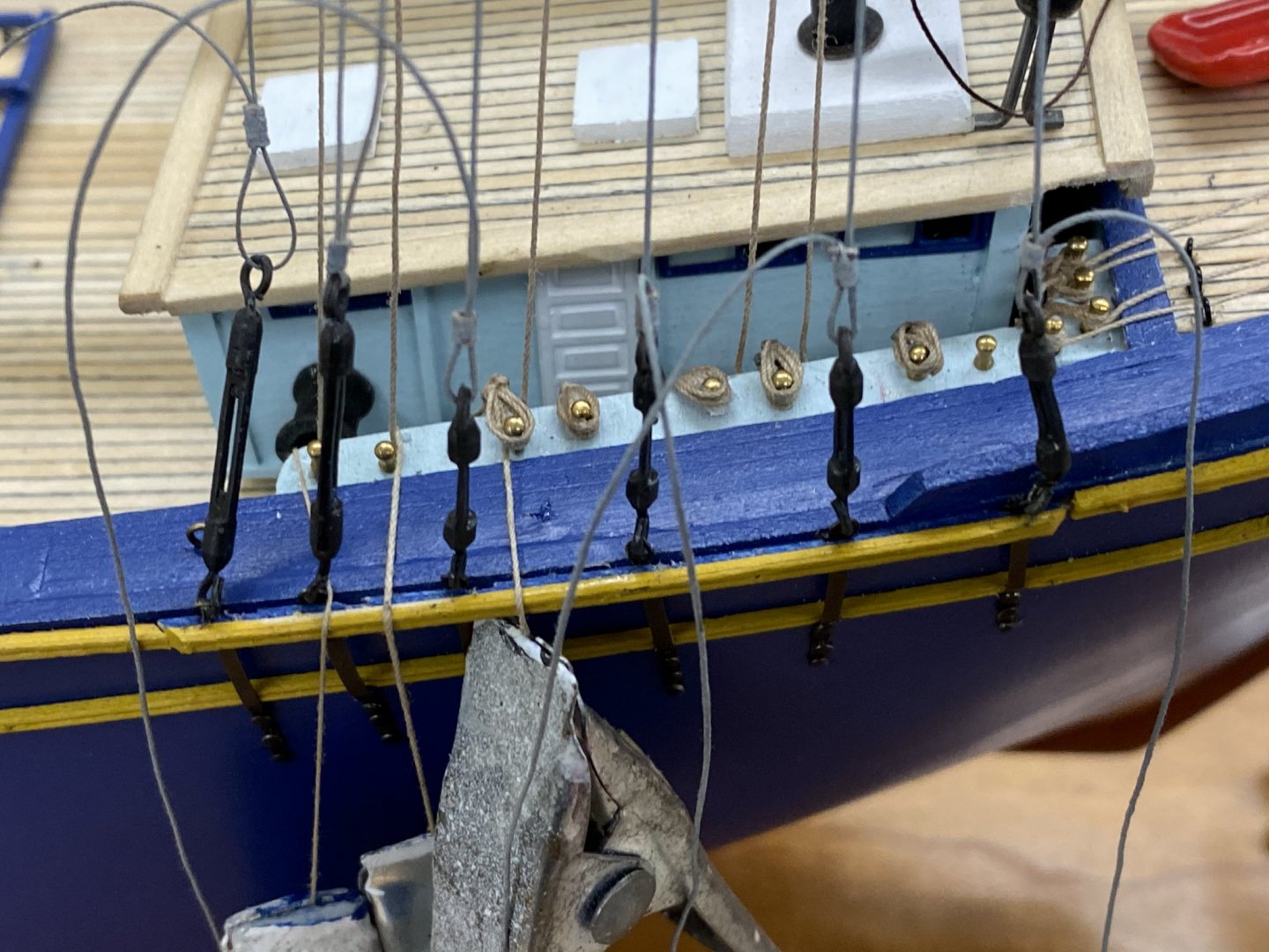
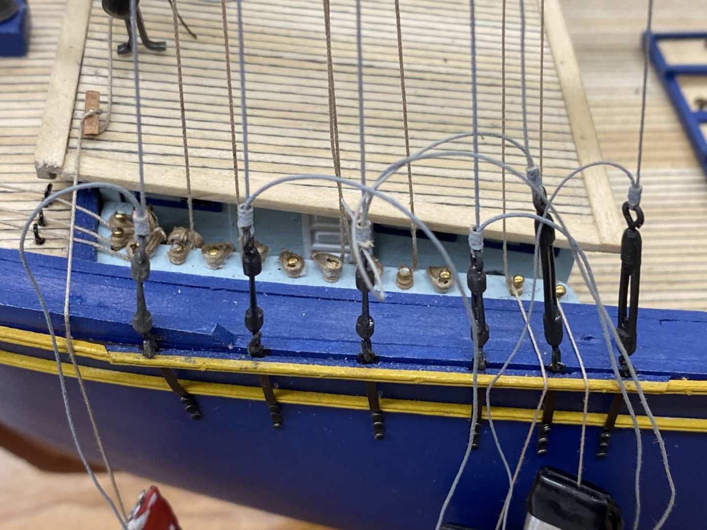
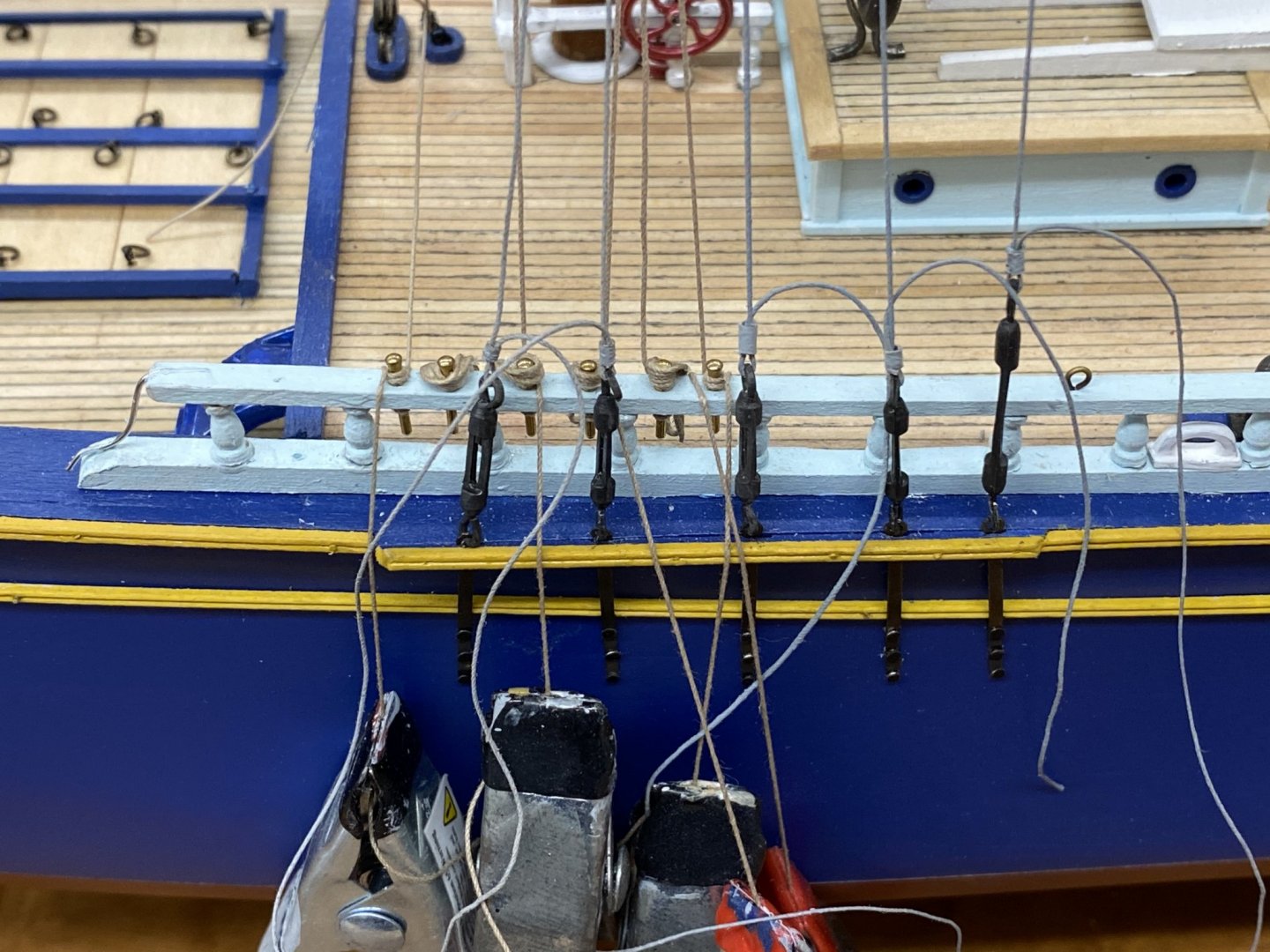
Turnbuckles arrived yesterday. After getting them cleaned up and blackened I started installing and running the lower shrouds. That is when it became obvious that I had grossly underestimated the amount of grey line required. back to the step ladder for more line painting. I did get the stbd side on the main mast lower shrouds rigged. I am confident that I have everything I need now to get the standing rigging completed. But I have thought that before.
- 144 replies
-
- 1
-
-
- charles p notman
- finished
- (and 1 more)
-
No turnbuckles yesterday - today for sure. I have all the running rigging just about done - mailman does not get here until the afternoon so I working the last few items (head sail sheet lines) and then can work the turnbuckles after they arrive and are blackened.
-
No turnbuckles in the mail today. Instead worked on the standing rigging on the foremast and bowsprit. I think I got all the standing rigging on the foremast/bowsprit complete except the topmast and lower shrouds and back stays - NEED TURNBUCKLES! That said here is where we are now - nothing is really glued down "for real" yet but everything is in place. Sorry for the mess - once the standing rigging is complete I will be able to move the model off the "woodworker work bench to a more photogenic location. Tomorrow (before the hoped for turnbuckle arrival) I will finish up the halyards on the foremast and the rest of the running rigging.
- 144 replies
-
- 3
-
-
- charles p notman
- finished
- (and 1 more)
-
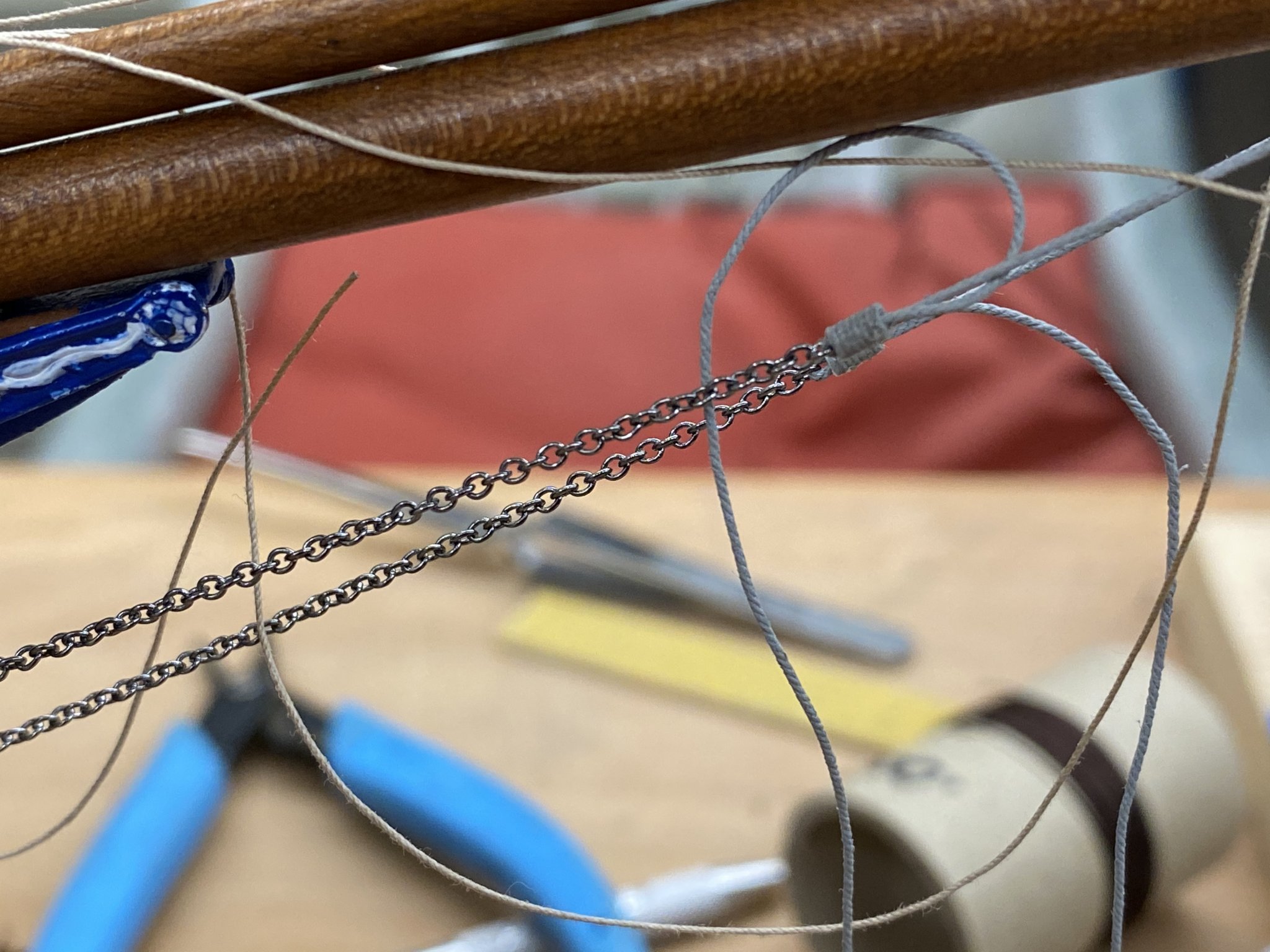
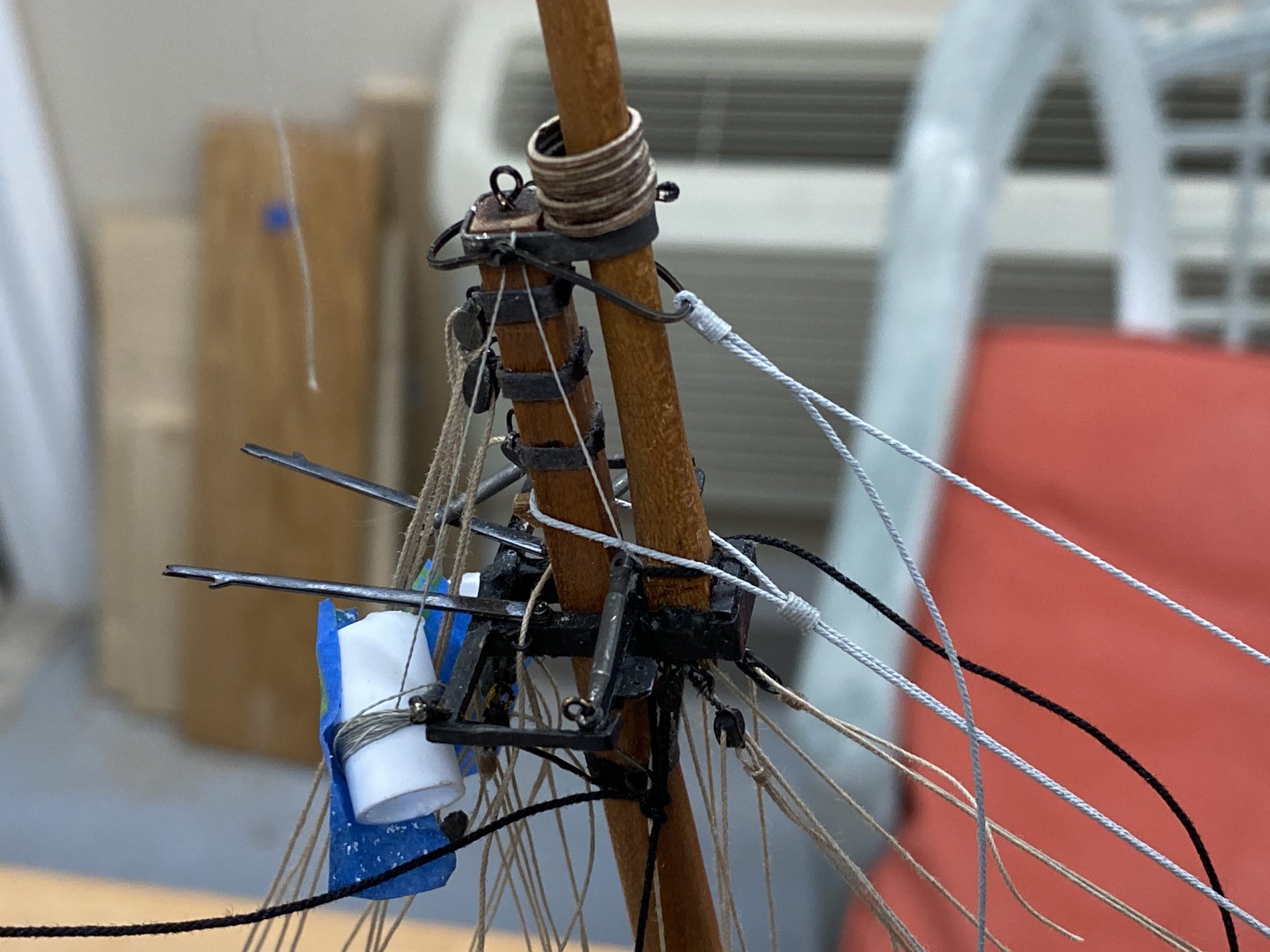
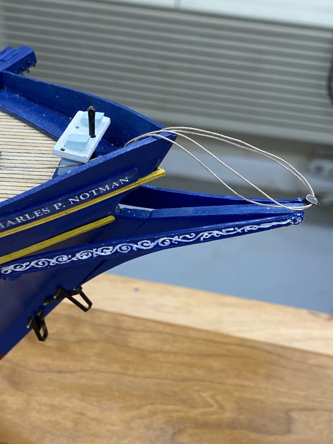
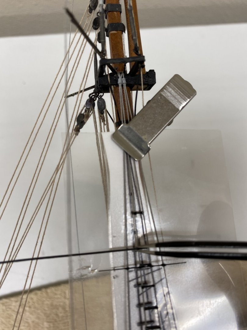
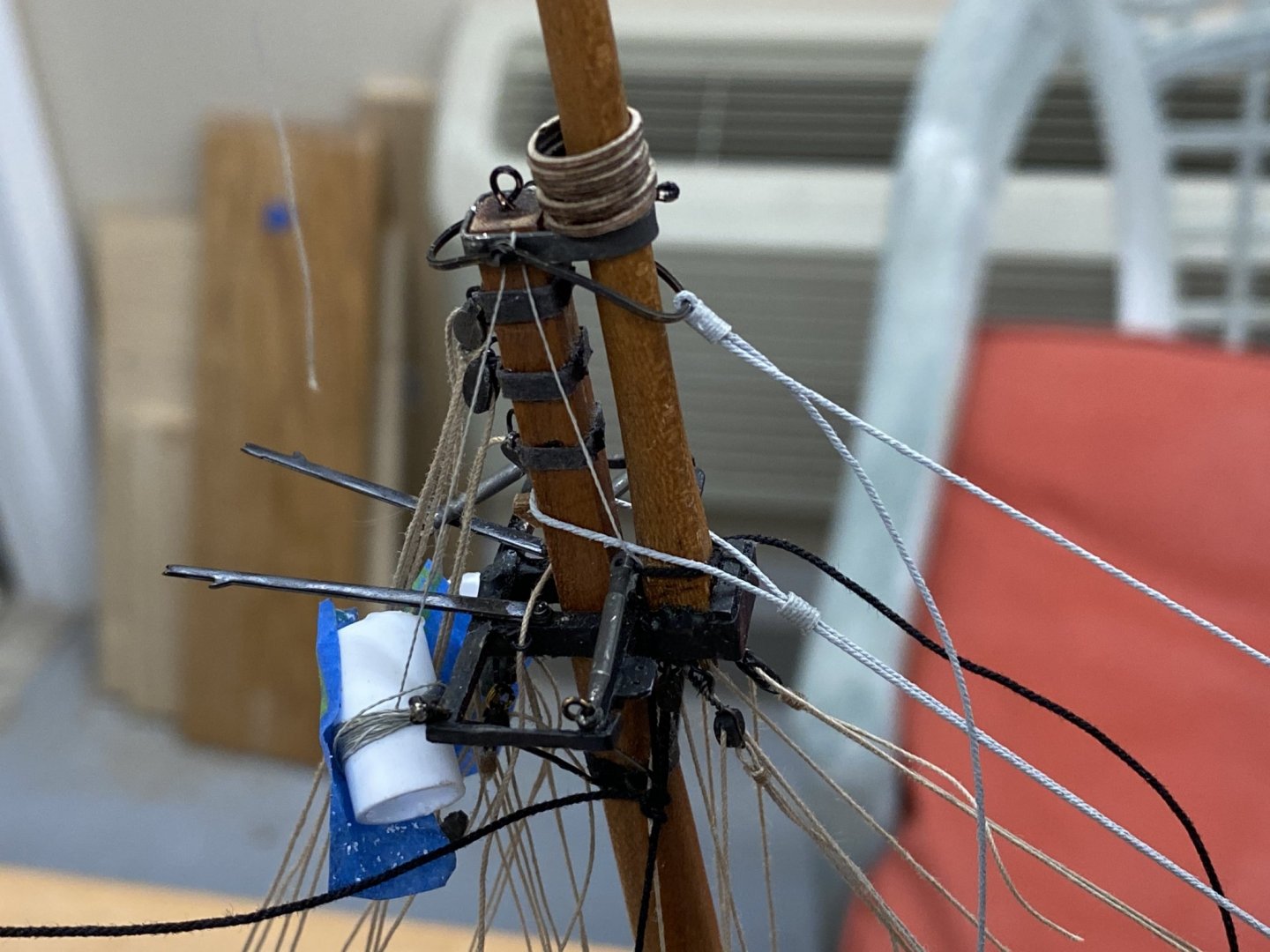
Working on the head sail stays and halyards. Rigged the Fore stay and Jib stay - Fore stay is secured by deadeye but deadeye lanyard is not secured yet. Got the topping lift, sheet lines and downhaul for the Fore Staysail. The same for the jib. Jib stay transitions to chain after passing through bees, then to iron on stem above the bobstays. Here it is at the mast head, at bees (see picture above) and transition to chain. I am going to try and get all the running rigging finished on the foremast before I start on the main and foremast shrouds. Hopefully the new turnbuckles arrive tomorrow.


- 144 replies
-
- 4
-
-
- charles p notman
- finished
- (and 1 more)
-
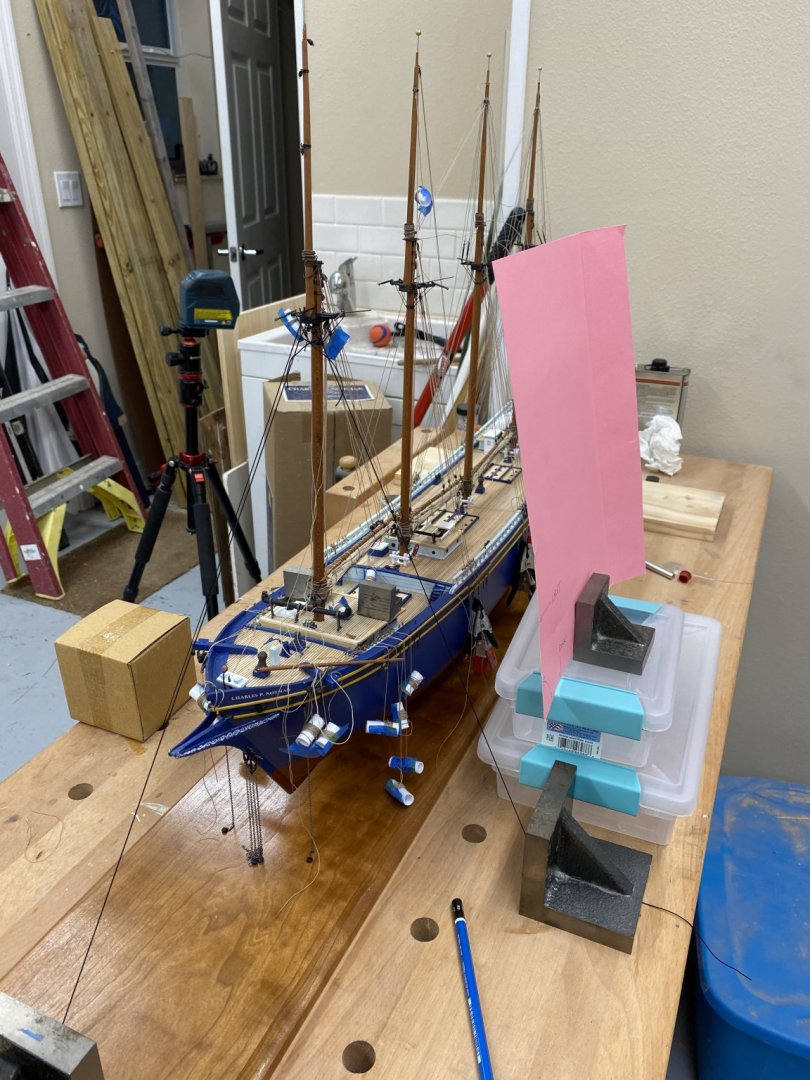
Foremast and Bowsprit are aboard - beginning to look like a real ship (model)! I am leaving the temporary shrouds in place until I can get the "real" shrouds in place. The replacement turnbuckles did not get here yesterday so I am working on the running rigging (mostly head sail halyards and the topping lifts for the two head sail booms) to keep myself busy. I looked at the .015 line (painted grey) I used for the Spring stays (Spanker-Mizzen; Mizzen-Main) and did not like the look or smoothness of adjustment so I painted some Syren .018 tan line grey last night and am going to use that for the standing rigging that calls for .015 thickness. Hopefully this will make it easier to get the correct adjustment since there are at least three other pieces of rigging that are affected substantially by the tension on the stays between masts. I have the model clamped to the wordworker's workbench until I get the shrouds on the Main and Fore masts. I can more easily keep the Fore mast correctly positioned vertically with the temporary shrouds with the base firmly positioned.


- 144 replies
-
- 2
-
-
- charles p notman
- finished
- (and 1 more)
-
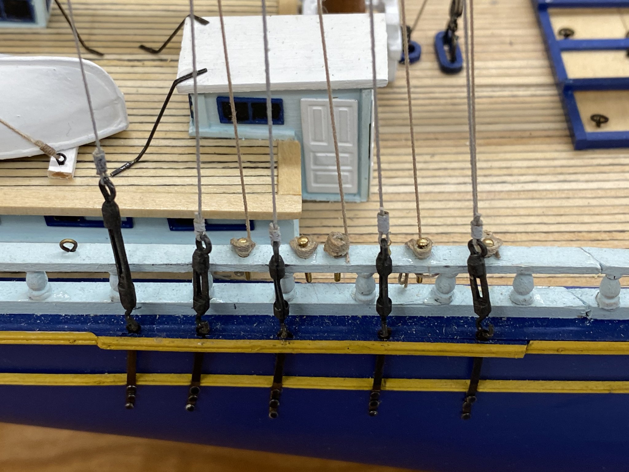
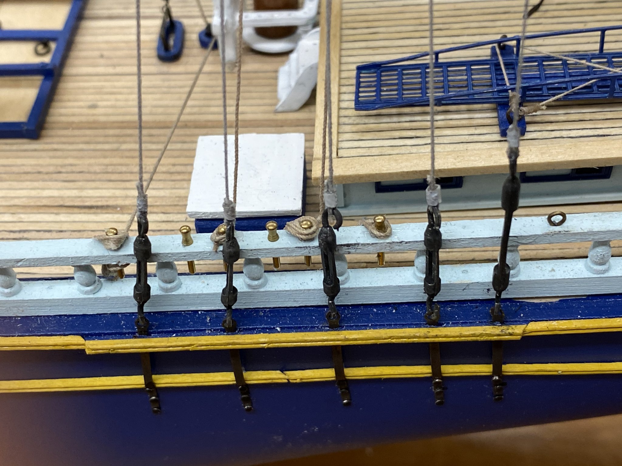
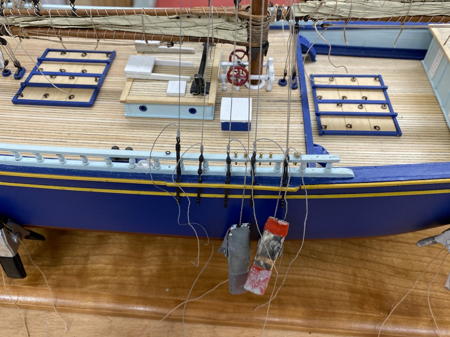
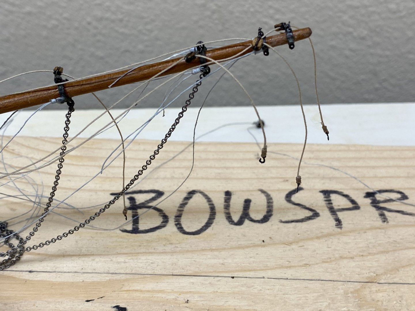
While waiting for the foremast/deckhouse to dry I added the downhauls for the four headsails to the bowsprit. I also added a 1/8" block for each downhaul attached to the "extra" eye at each of the jib boom irons. I thought I read somewhere in the instructions about using these as fairleads for the downhauls but they are not oriented correctly. For the fairleads I used 1/8" wooden blocks stained walnut. I ran out of metal blocks and grew tired of having the attachment or becket fail. I think I am DONE with the metal blocks. So here is the bowsprit with the downhauls and blocks added.

- 144 replies
-
- 1
-
-
- charles p notman
- finished
- (and 1 more)
-
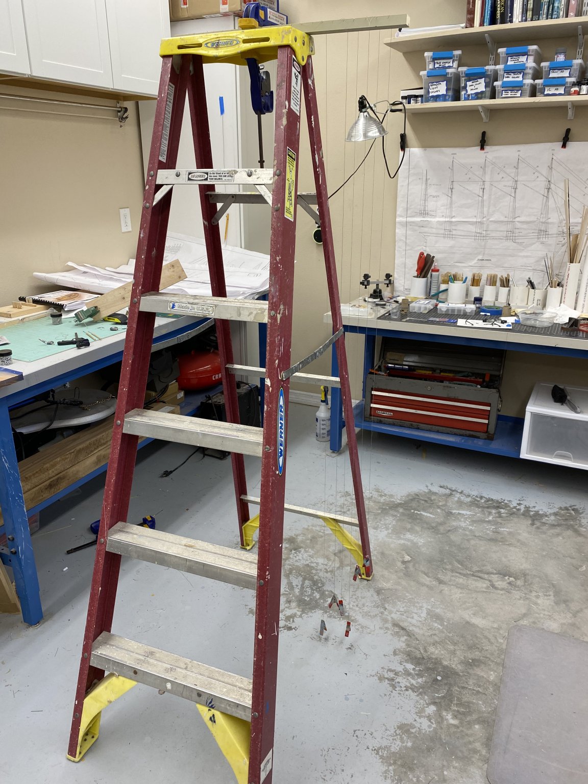
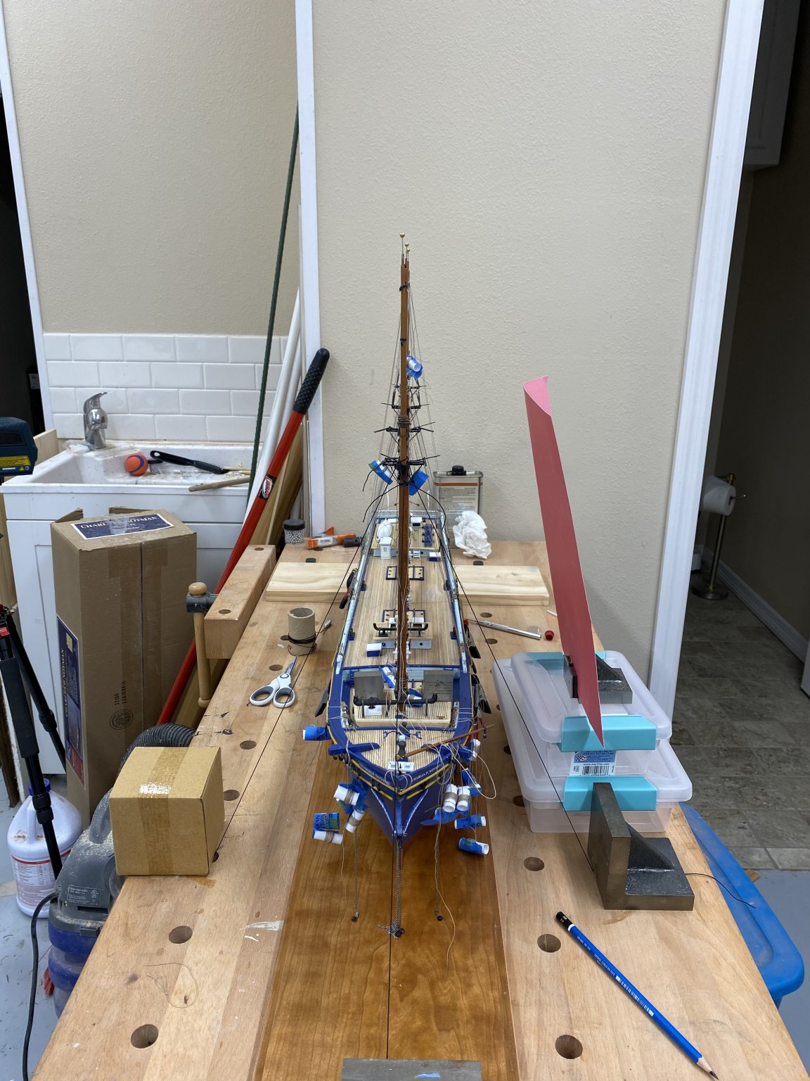
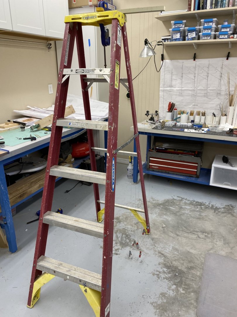
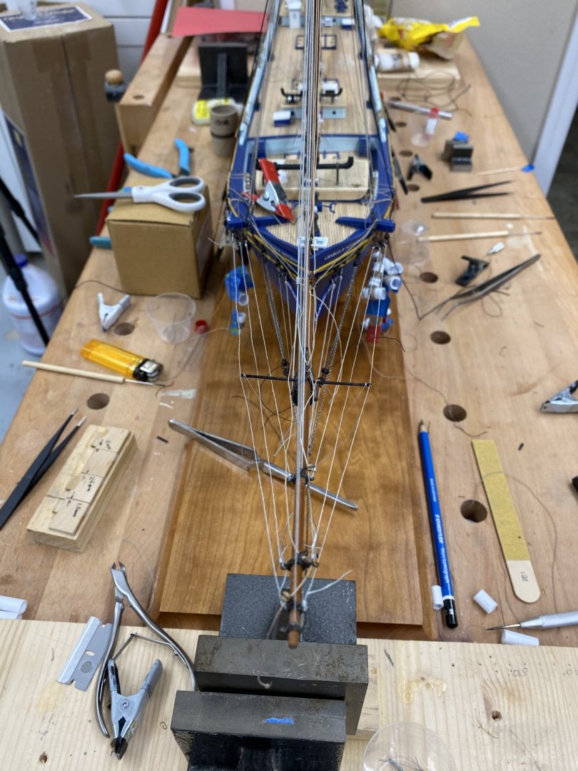
Ready (except for the turnbuckles for the forward two masts) we are for the forward deckhouse and mast to "come on down" as they used to say (or maybe still do) on "The Price is Right. Since there are more moving parts in this install I rigged up lines port, starboard and forward from the foremast to weights to allow me to adjust the pull to get the mast aligned as required. I also put some weights on top of the forward deckhouse as its position also plays into the foremast positioning. Here is how it looks from forward - all the masts seem pretty much in line, even though none of them have the standing rigging taut. They may be off a little at the topmast portion - hopefully I can pull this in with the topmast shrouds and back stays. Here is how the mast rack mlooks That assumes that my base is close to level, which I think it is. Here is the rest of the set up showing the lines to control the foremast position. Now for the hard part - taking it all apart, applying the glue and then getting everything back in this position. We do that tomorrow

- 144 replies
-
- 2
-
-
- charles p notman
- finished
- (and 1 more)
-
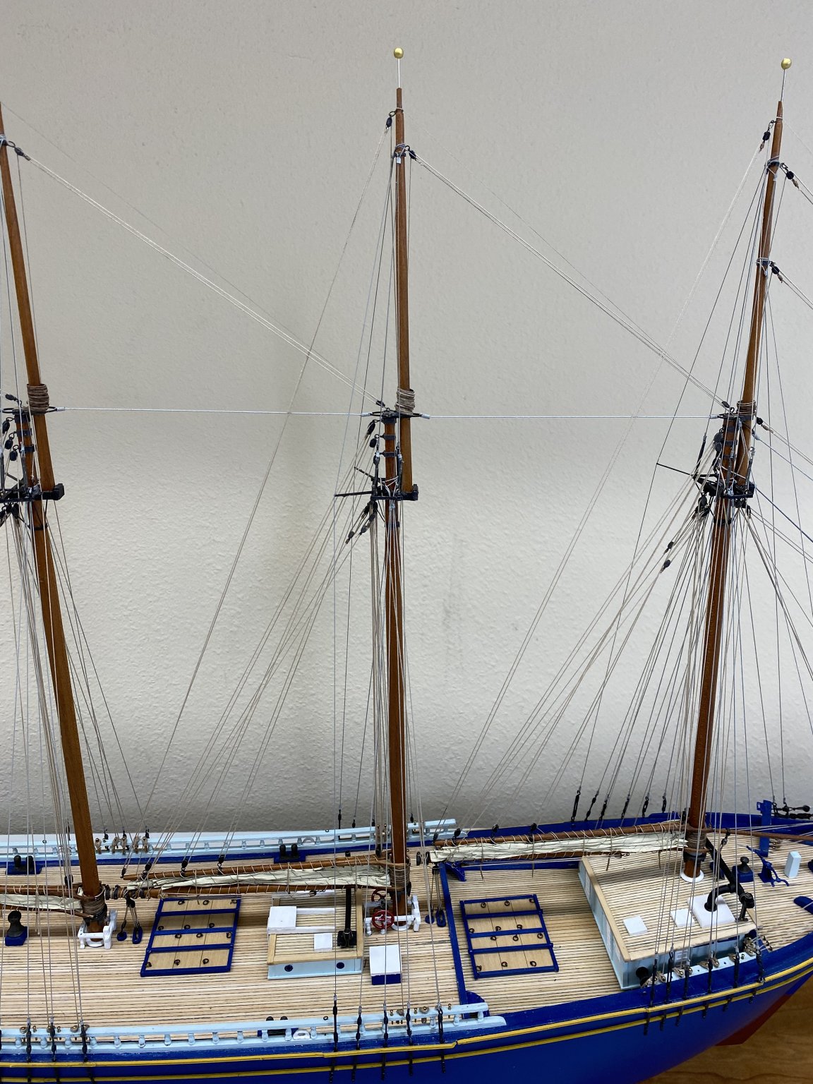
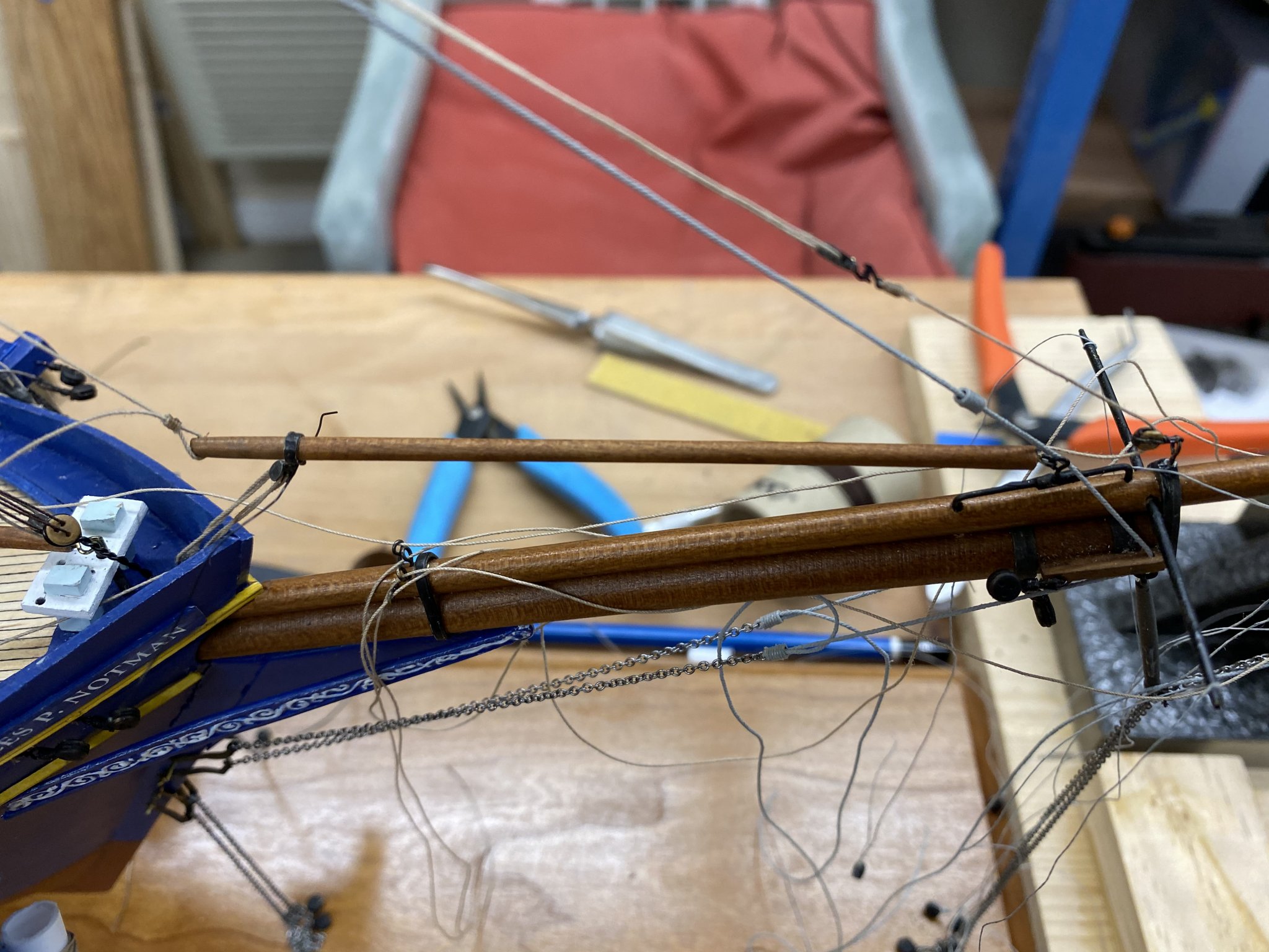
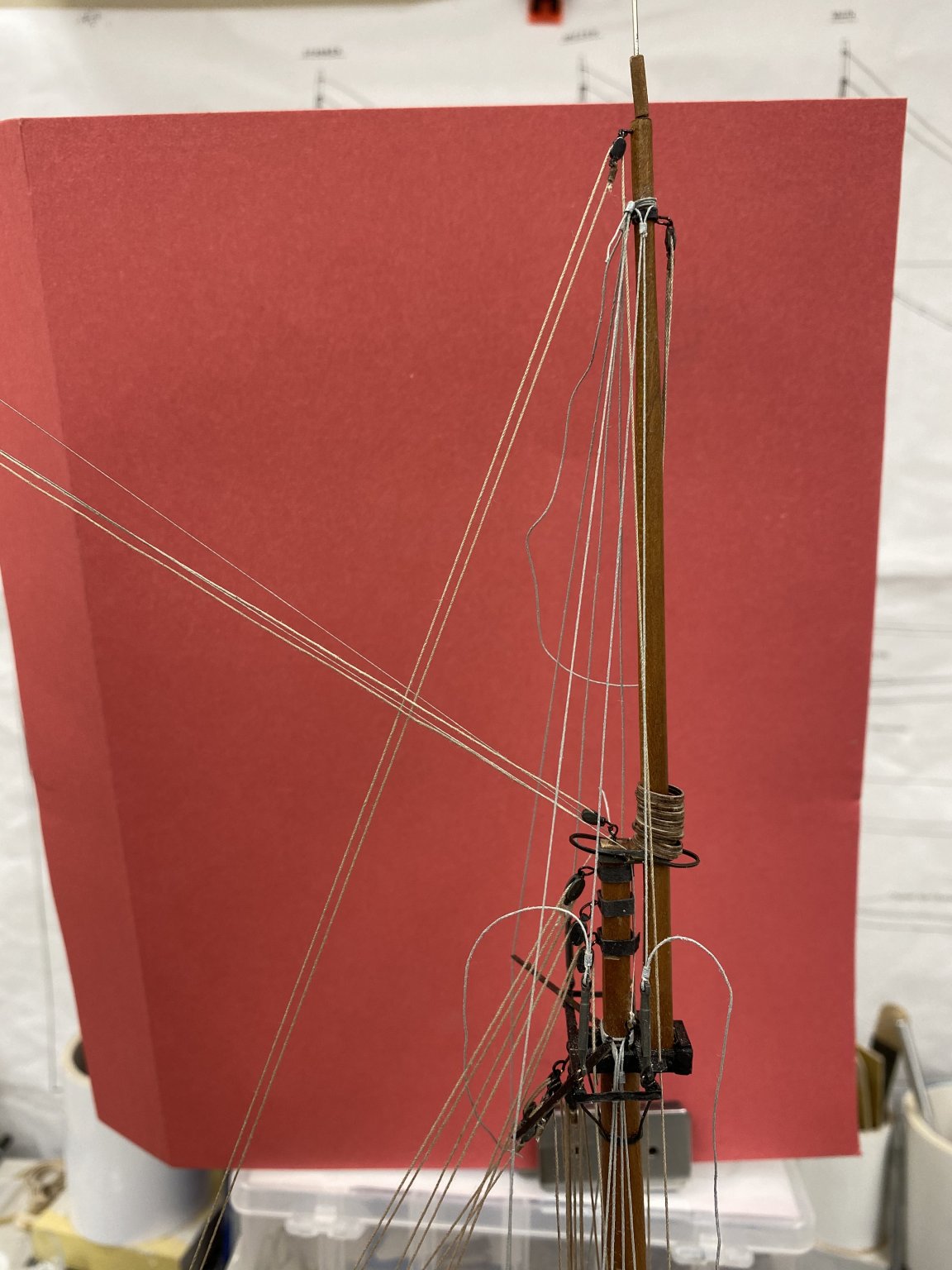
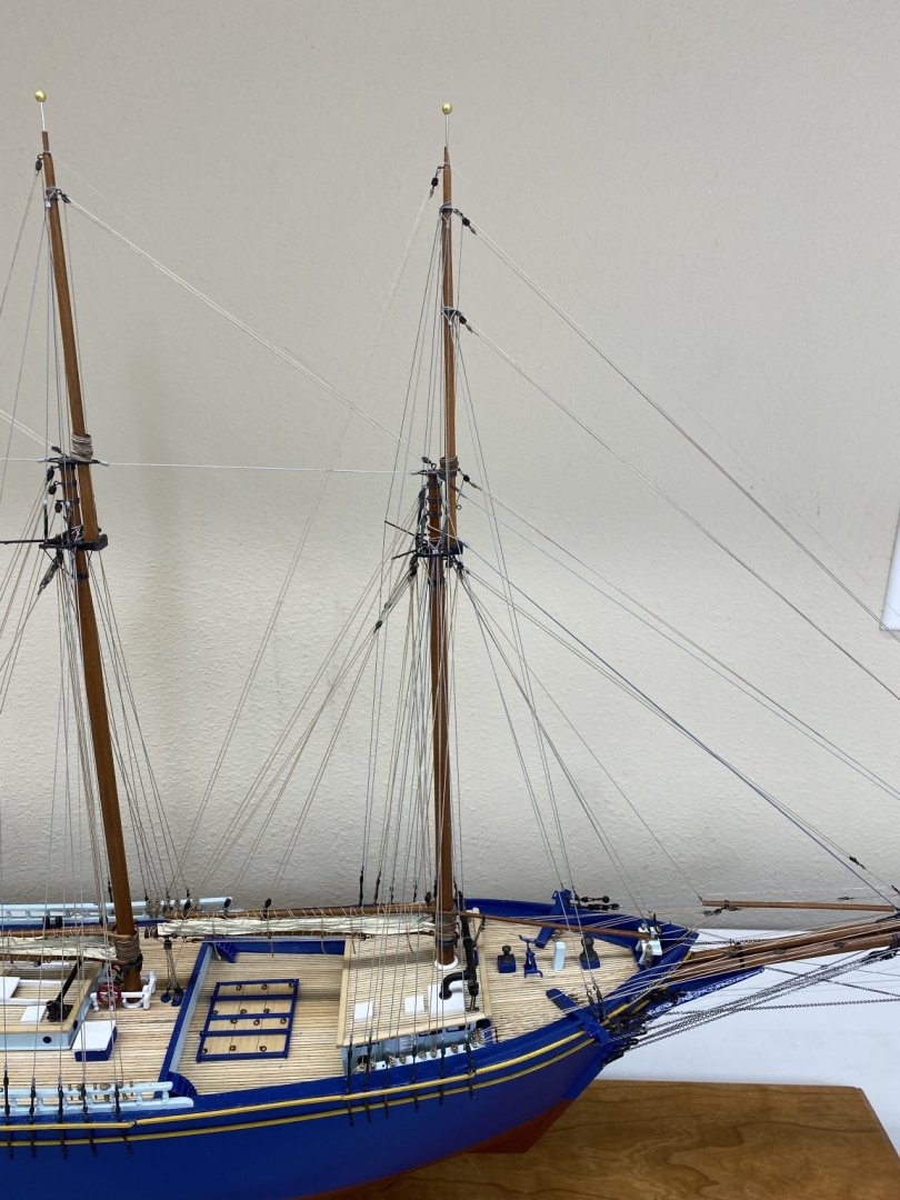
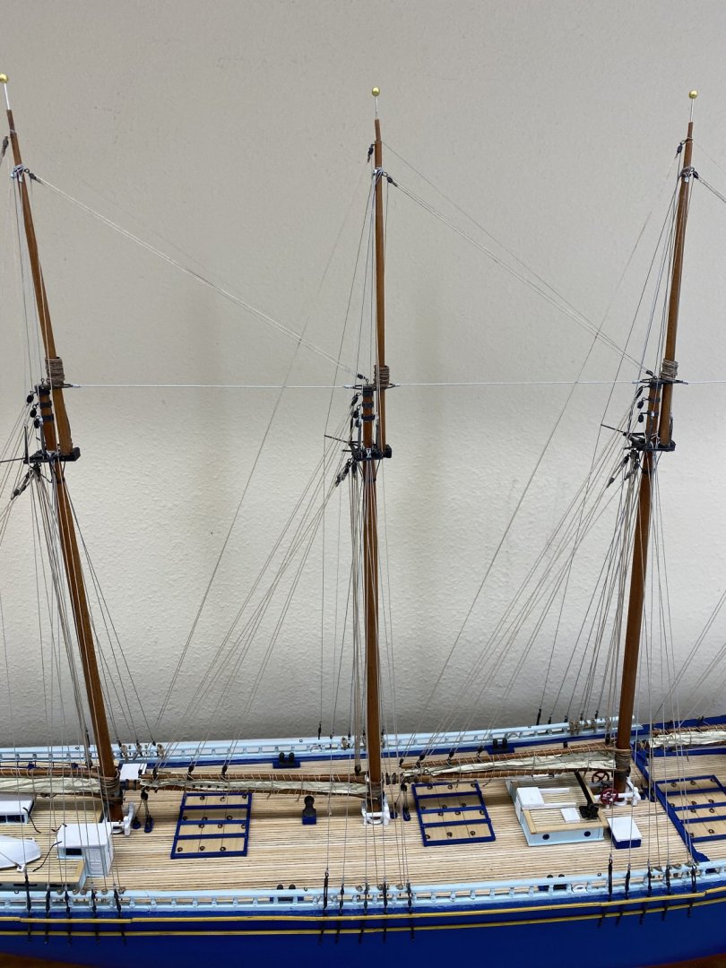
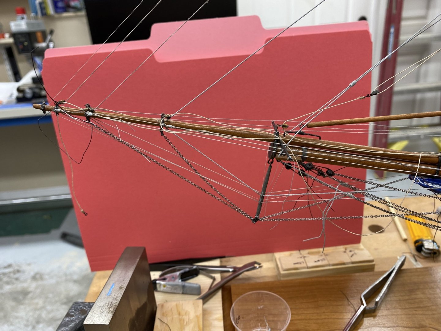
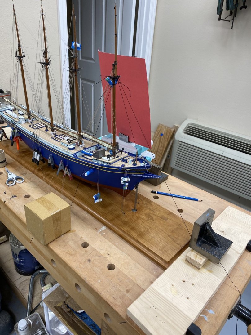
And then there were THREE (masts). Mainmast is abroad but not yet rigged. Therein lies the problem. The turnbuckles which secure the lower shrouds are not as sturdy as I might like. The parts list shows 36 of the small (eight per mast (32) plus four (4) for the fools/cap stays on the foremast). comes with the kit. I suspect there are a few spares included but not enough for the ham handed (like me). The eyes that must be opened to hook the turnbuckle to the chain plate is good for only a small number of bends before it breaks off rendering the turnbuckle useless. Perhaps I should have painted them rather than chemically blackened them. Maybe the blackening reduces their resistance to fracture in some significant way. In any event, I have two of the four mast standing rigging done and have less than four turnbuckles remaining. So another 30 are on the way from BlueJackets - should be here Saturday (I hope). In the mean time I intend to get the mainmast running rigging belayed and then move on to the real fun - the foremast. I will work the standing rigging when the turnbuckles get here. I would also suggest that anyone building this kit leave the wooden battens that run through the turnbuckles out until all the standing rigging as been tied off and secured. I think the jockeying around getting the batten inserted and then moved around as the standing rigging is added may have contributed to the turnbuckle breakage. To make the battens as easy as possible to insert I thinned them down to 1/64" rather than the 1/32" called for in the instructions. I might substitute some styrene (of the appropriate dimensions) for the wood as it is easier to maneuver in through the slots in the turnbuckles (and it doesn't break easily).
- 144 replies
-
- 2
-
-
- charles p notman
- finished
- (and 1 more)
-
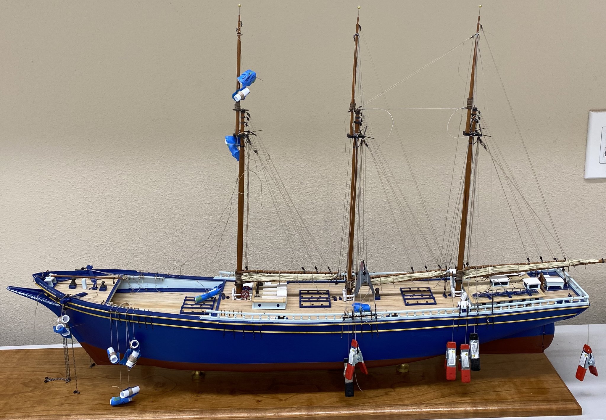
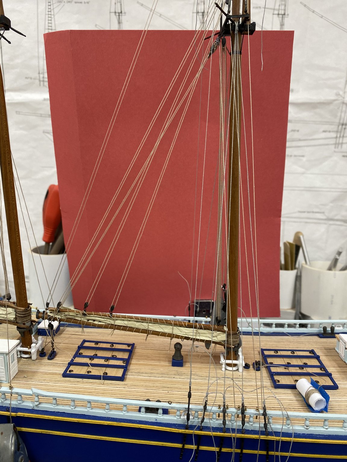
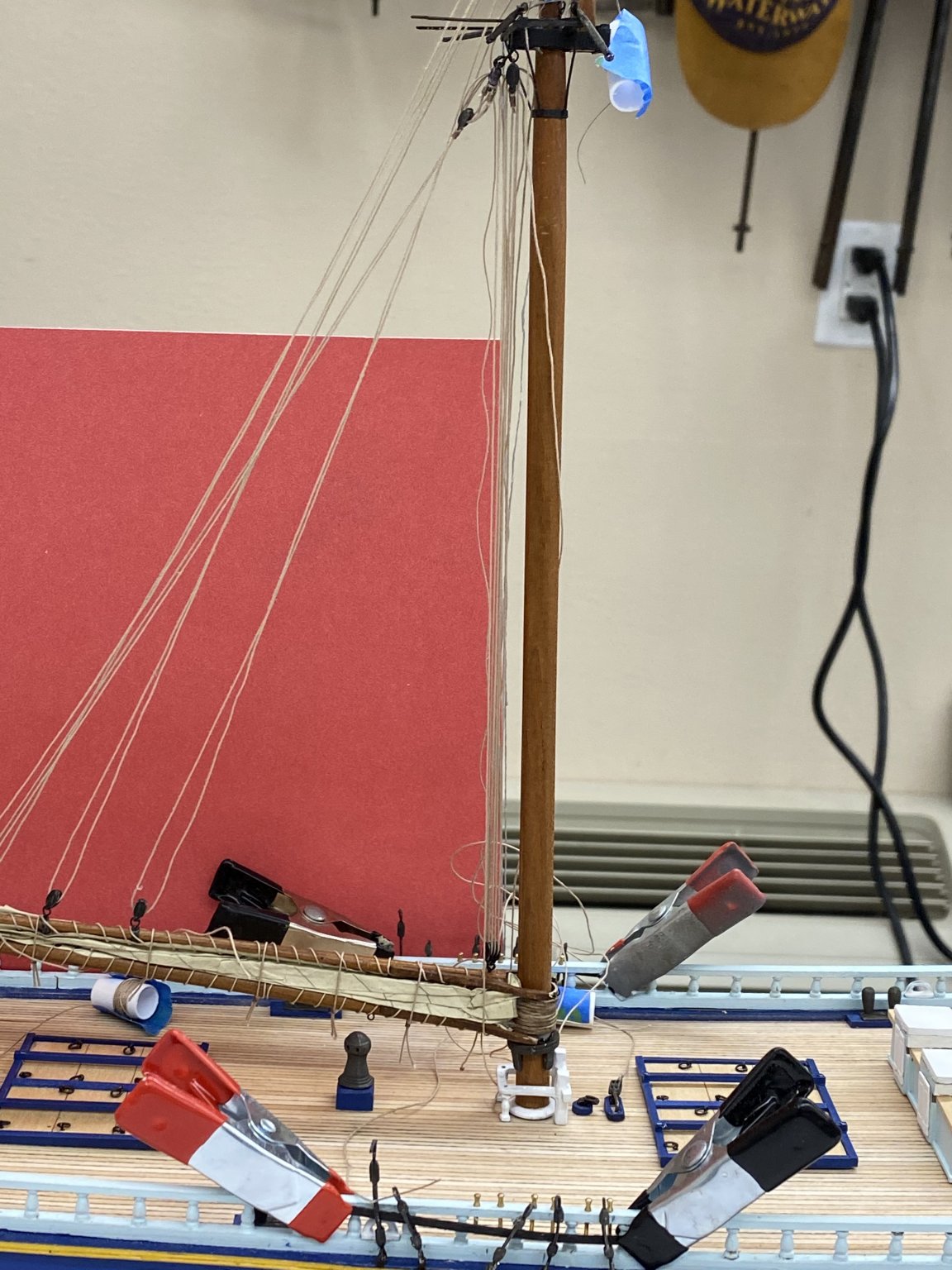
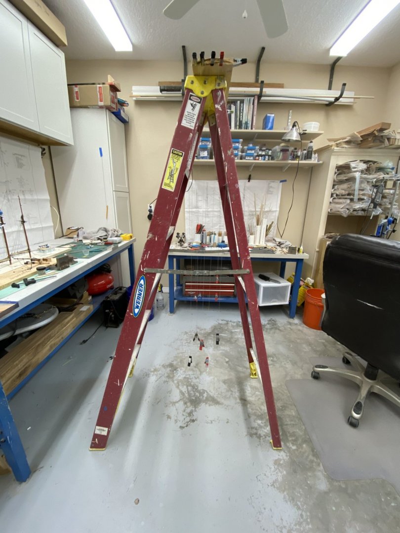
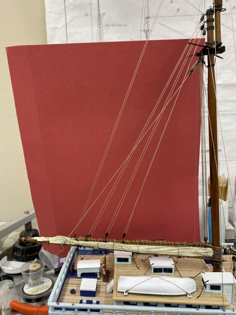
Having decided to use painted line (rather than Beadalon nylon coated wire) for the standing rigging I used a step ladder to hang the line while it dried. In my first attempt I poured a small "puddle" of paint (Badger grey primer) and pulled the line ( kit supplied) through the puddle of paint and then hung it up to dry. This did not work out so well even though I ran down the line between my fingers as it hung the paint still dried with noticeable "bumps" in various places. Part of this is the line which is not as consistent as you might like, and the other is probably the paint which was pretty thick. After scraping that line I cut the paint 50/50 with water in a small cup and essentially submerged the line in the thinned paint then pulled it out between my fingers and hung it up to dry. I also shifted to Syren .012 and .008 tan line (for the .012 and .010 line called for in the instructions). I am continuing to use the kit provided line for the .015 thickness. With the Mizzen aboard and while waiting for the painted line to dry, I put the Spanker aboard and tied off the running rigging.I used the laser and template to get the rake and side-to-side alignment with the Mizzen. With the two masts aboard I started to add the standing rigging, although nothing (running or standing) is glued in place yet. My plan is to wait until I have all the masts and bowsprit aboard and rigged, then CAREFULLY tie off the rigging mast-by-mast starting at the bow since that is where all the forestays are. So here is the Mizzen with all of the running and standing rigging (except the Spring Stay to the Spanker) in place. Forgive all the excess lines - I am leaving them long to make it easier to grab them if necessary. And here is the Spanker with just the running rigging (no standing yet). After I get the standing rigging on the Spanker the Mainmast is next. I am considering securing one mast at a time (starting from the bow) and then adding the "ratline steps" to one mast at a time before securing the next mast. The thought of doing 240 steps with nothing else to do in between does not appeal to me much.


- 144 replies
-
- 3
-
-
- charles p notman
- finished
- (and 1 more)
-
Nic, I had not thought of putting the line through the hole and then putting the pin in. The holes in the forward pin rail are a bit large for the provided pins so that might be the preferred solution if I had not already gone "the other route". Having the running rigging behind the standing makes tying ratlines somewhat more complex but they do provide a convenient support for the ratline template. I laminated mine on this job to reduce the possibility of gluing the template to the shrouds. We will see how that works in practice as I am still "raising masts" at this point.
-
I reread the instructions and did find ( bold at bottom of page 60) where it indicates the order for installing the masts: Mizzen, Spanker, Main and Fore. No explanation of why but as always "we follow the instructions (more or less)". The instructions also say to rig the running rigging before the standing, at least to run the running rigging to the belay point, take up the slack but "DO NOT GLUE YET". I am still thinking about that. I am inclined to rig the shrouds/stays as I put the masts aboard to minimize the amount of "stuff" that might get in the way while rigging the shrouds on a given mast. Leaving the Foremast to the end means installing the Bowsprit after all the masts which is probably a good thing as I am always nervous about something catching on the Bowsprit/jib boom once it is aboard. Anyway, once the Mizzen is secure (glue dry) I will proceed with the Spanker etc.
-
Thanks V. My father (who grew up in Fall River, Mass.) told me seeing three and four masted schooners like the Notman was quite common in the late 1920s in the local waters.
-
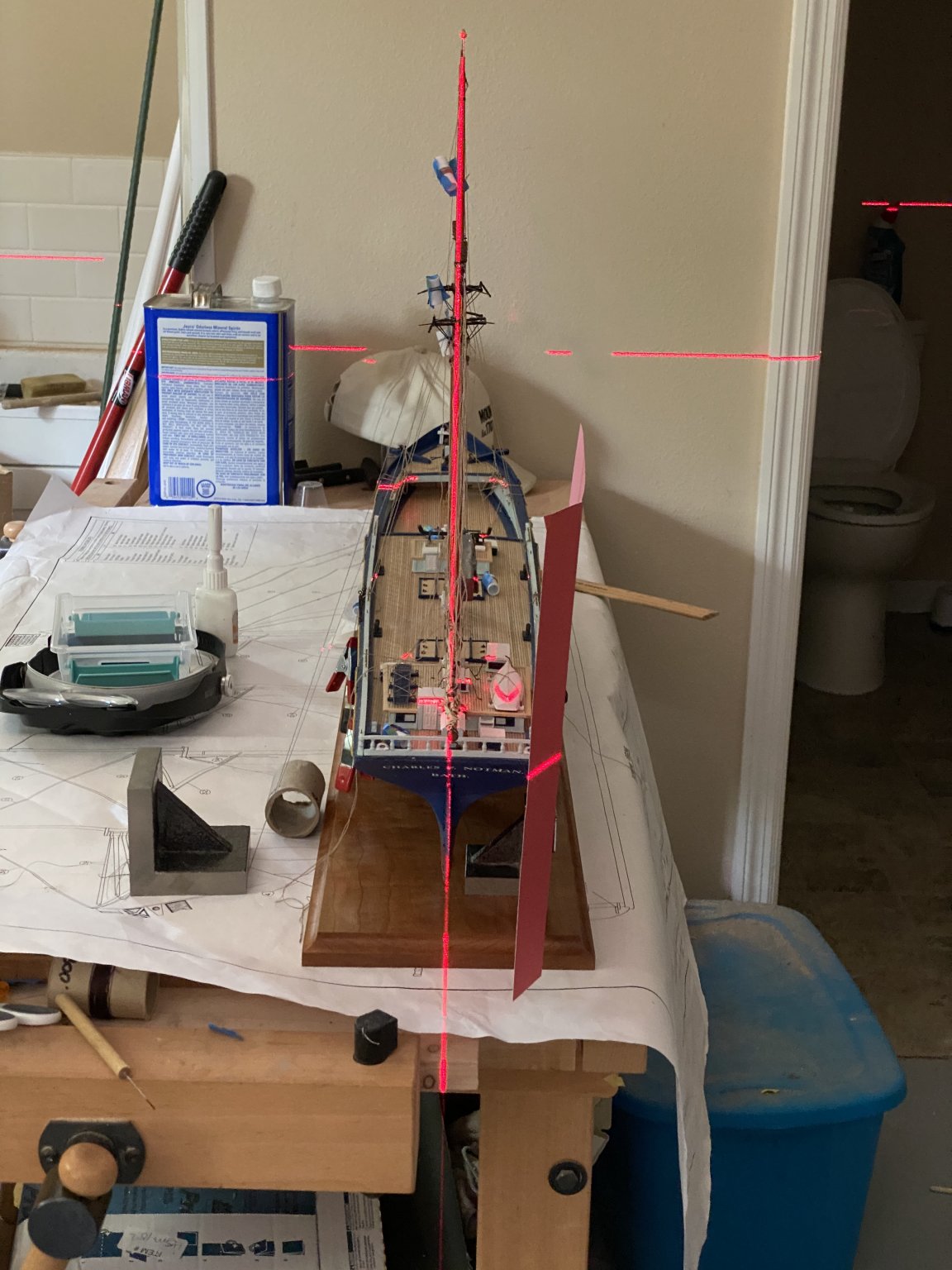
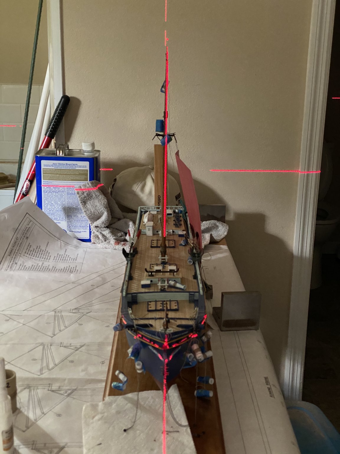
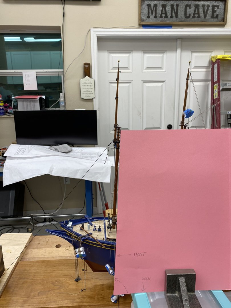
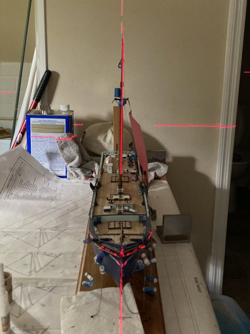
A mast! a mast is aboard. I took the instructions advice and mounted the Mizzen first - not sure why but... To accurately get the mast rake I created a template from a file folder using the waterline on the sheet 5 of the plans as the reference. I lined a cut edge of the file folder along the Mizzen (although all the masts are supposed to be the same) and marked where the waterline cut across the folder. Then I c arefully marked and cut along that line and checked that if I aligned the edge I cut with the waterline that the other edge aligned with the mast. Then I put the waterline edge on the table an d checked to see how the mast lay. It was pretty close so I sanded a b it off the back side of the mast that fit in the hole in the hull and tried again. Although not really easy to see in the below picture the mast and template are in pretty good agreement. Then I set up the laser level to check the side to side alignment. I set up a temporary shroud on the side that needed the pull and adjusted to get the vertical laser beam to run up the center of the mast. When I had it correct I pulled the mast (and fife rail and mast coat) off the ship, added a small amount of Weldbond glue around the inside of the hole in the hull and put everything back an d readjusted to get the laser on the mast. Now, wait for the glue to dry and then try a keep everything in line while putting the shrouds/stays on.

- 144 replies
-
- 3
-
-
- charles p notman
- finished
- (and 1 more)
-
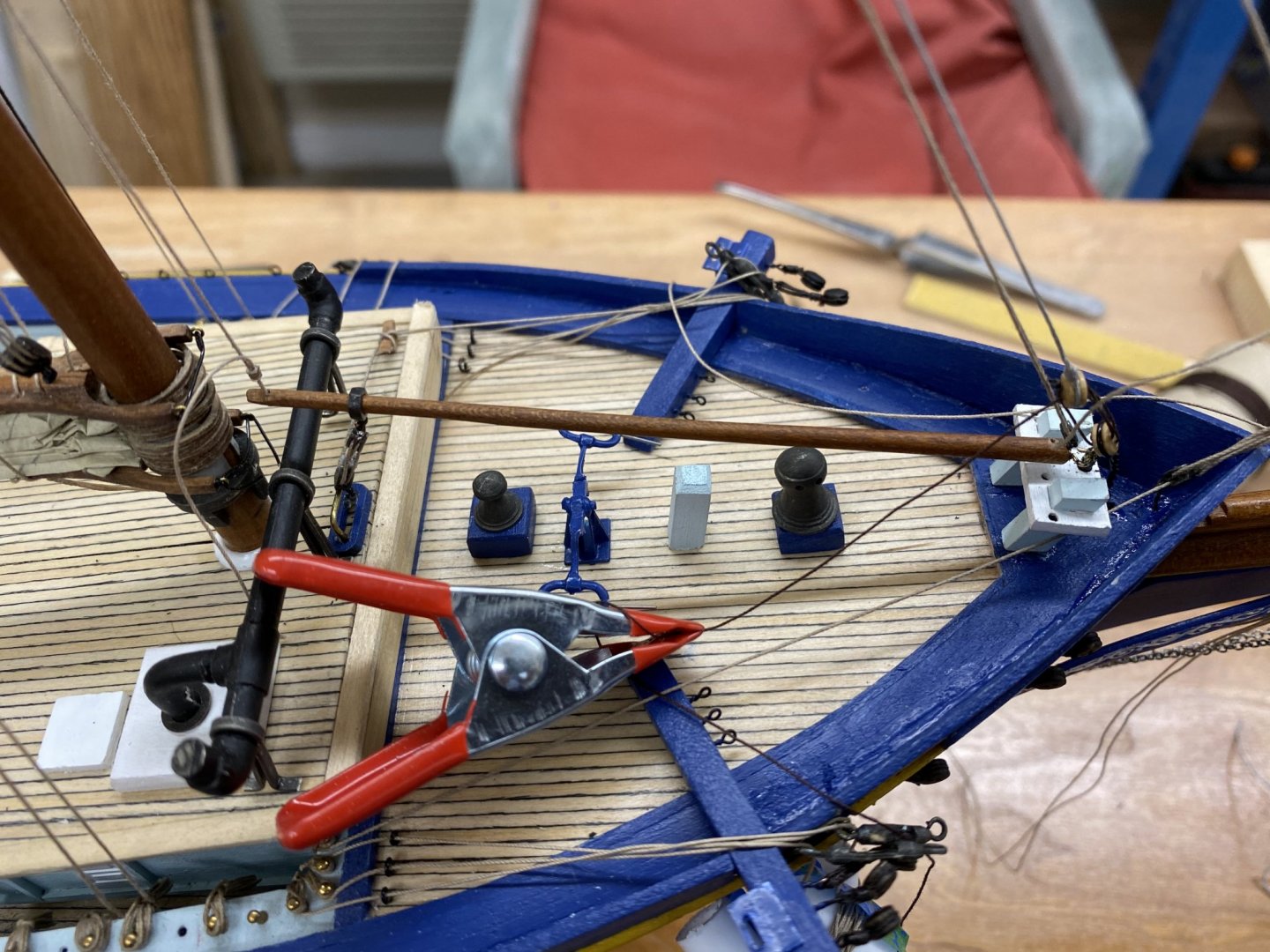
After looking over the way ahead it occurred to me that perhaps my tactic (and that generally recommended throughout this site) of pre-outfitting the masts with blocks and lines to the maximum extent possible may not have been prudent in the case of the Foremast. It looks like there will be very little "room to maneuver" between the forward deckhouse and the pin rails abreast the Foremast. With that in mind I decided to "unrig" the halyards and topping lifts (except the boom topping lifts and throat and peak halyards) from the Foremast and instead terminate them at the belaying pins before installing the Foremast and forward deckhouse. While I am not a big fan of trying to terminate a running rigging line at a becket on a block already attached to the mast, that seems a better plan than trying to terminate a line on a belaying pin that is assess able only through a 1/4" wide slot. So here is what the main deck looks like with the five halyards, two topping lifts and four sheet lines on the respective belaying pins. I have not decided what to do about the empty holes in the pin rail. I believe I will fill most of them with pins and some of those with rope coils like the ones on the port side. The boom topping lifts and throat and peak halyards are "too hard" to undo and redo so I am leaving the last two pins on each side for them. I think I can get to them with the deckhouse in place. That is not where the belaying plan would have them go but "I am the Captain" as they say and I am sure the belaying plan was well within the Captains purvey to change - even on a merchant vessel.
- 144 replies
-
- 1
-
-
- charles p notman
- finished
- (and 1 more)
-
I have gotten the bowsprit/jib boom as complete as possible without actually rigging lanyards on the deadeyes or running the fore stays. It is back on its stand to await it calling after the masts are aboard. I also built a cradle for the gangway and mounted it atop the after deckhouse. While doing that I noticed that one of the fairlead "irons" from the top skylight has gone missing. I should have made a few extra when I was at it as this is the second time one of them has turned up missing. Oh well.

- 144 replies
-
- 4
-
-
- charles p notman
- finished
- (and 1 more)
-
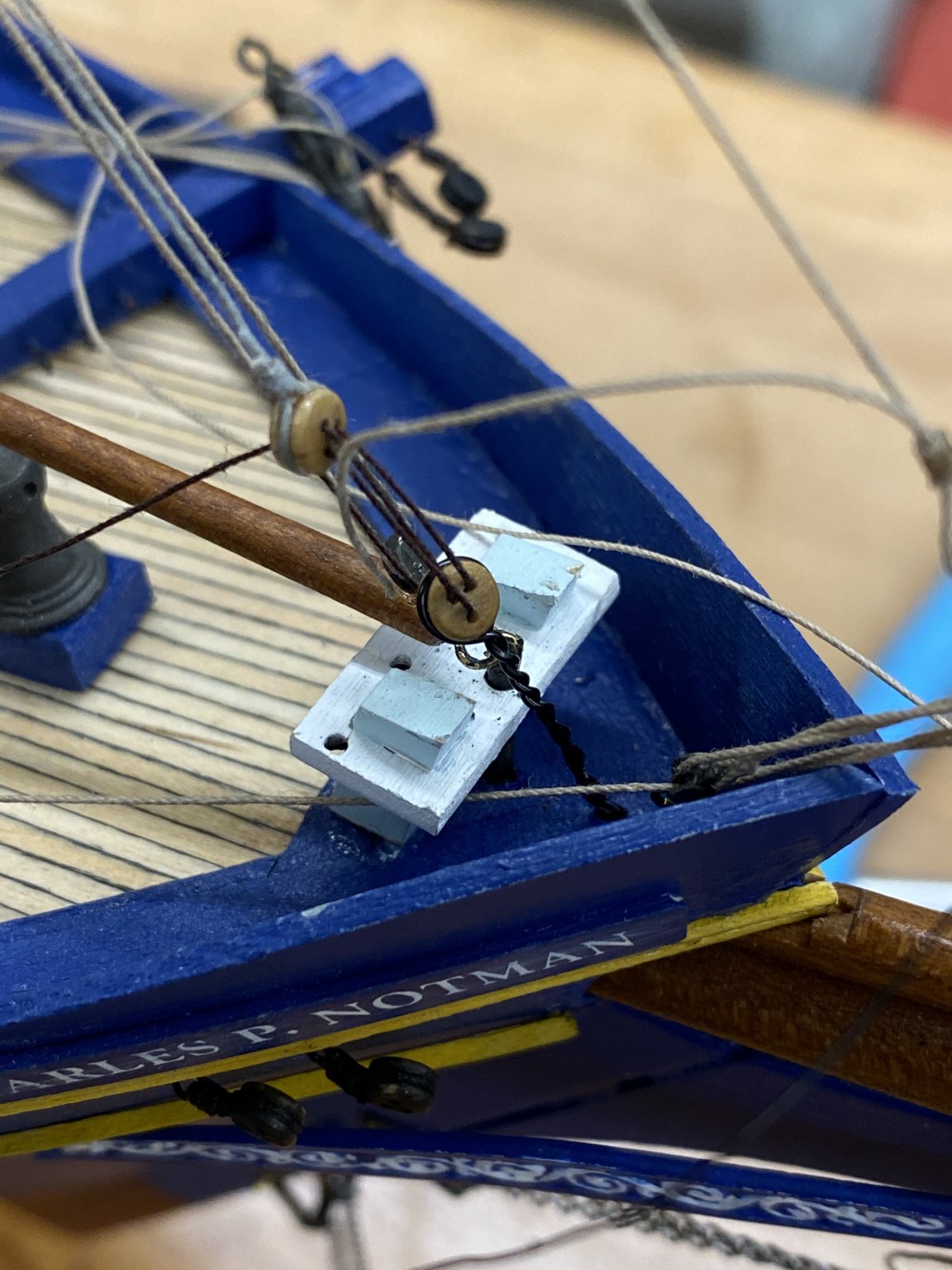
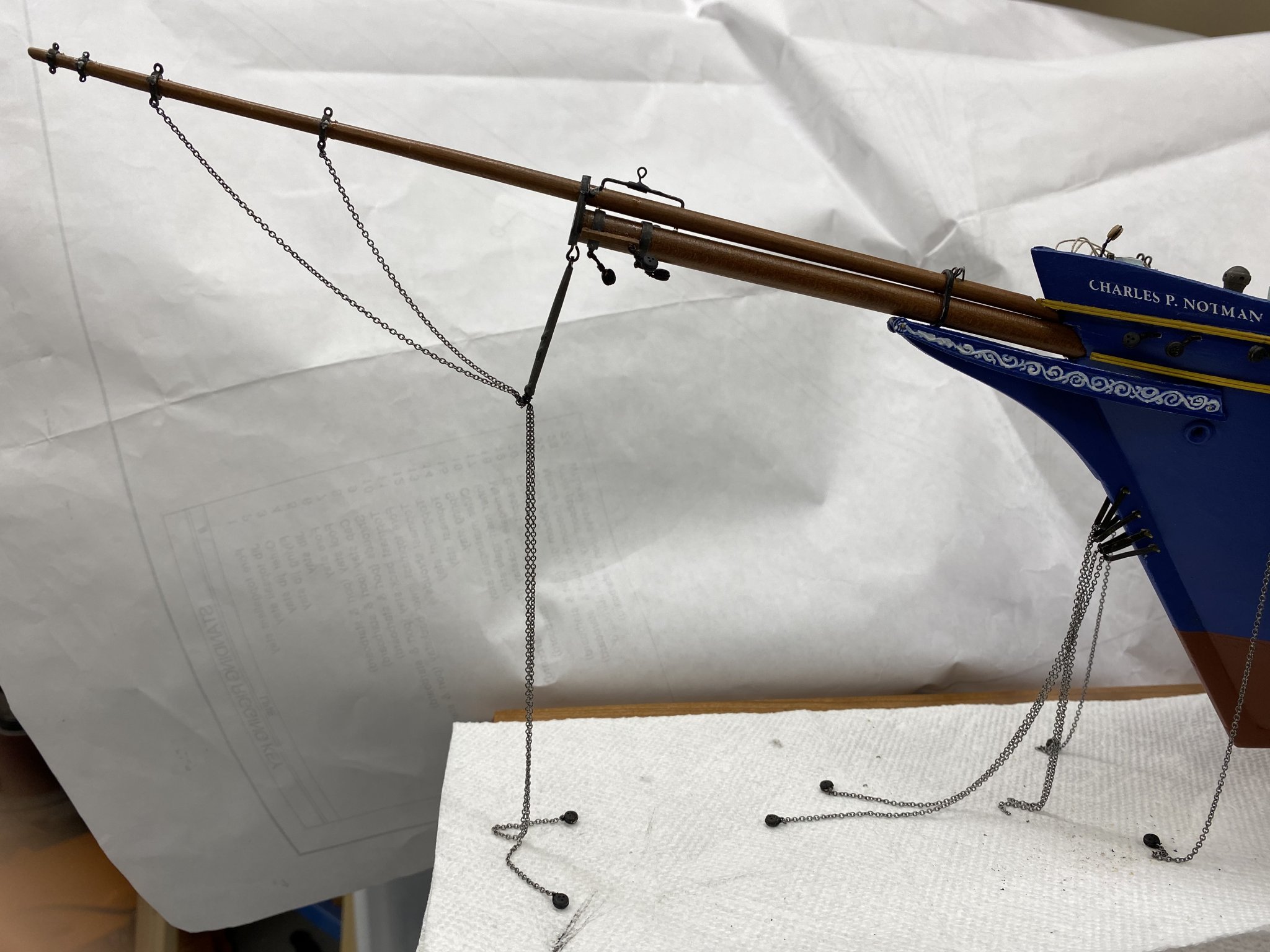
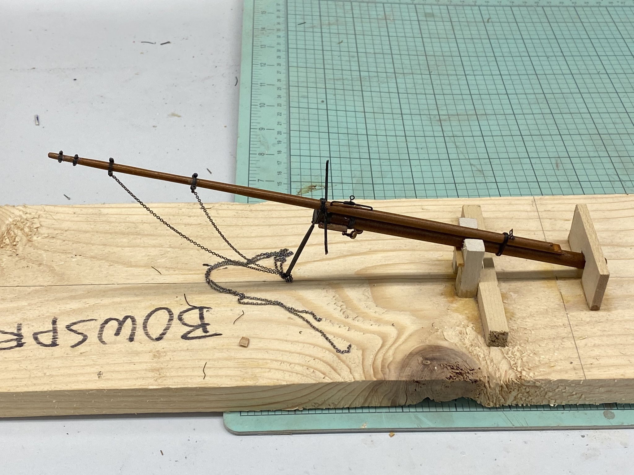
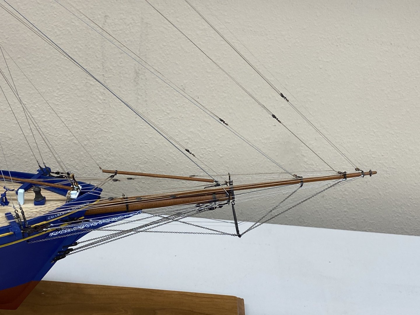
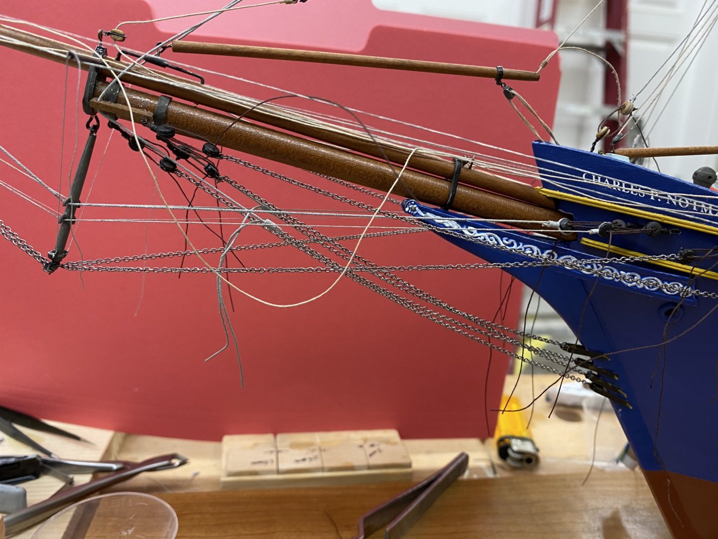
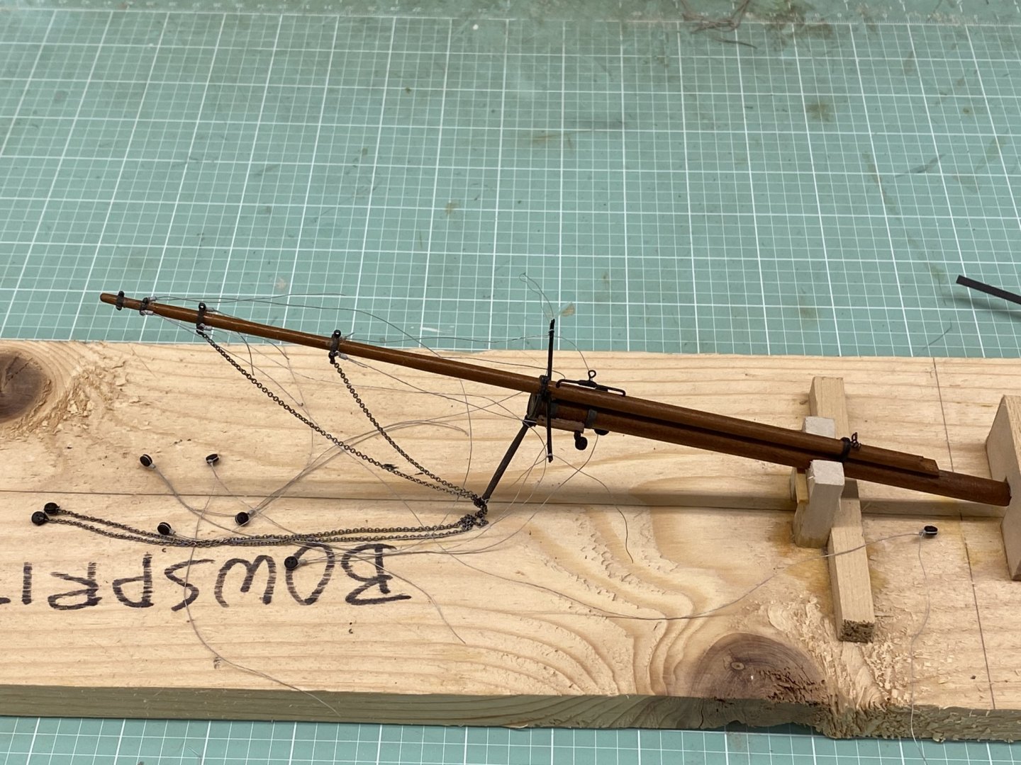
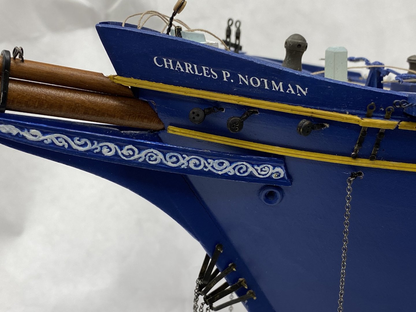
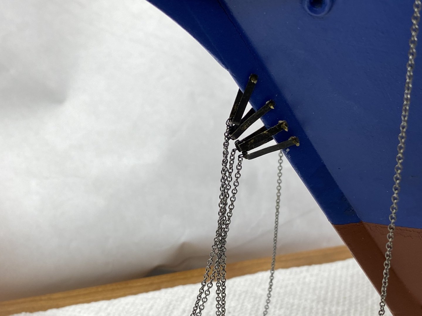
I mounted the bowsprit/jib boom (dry fit - too big a chance of damage while fiddling around getting the masts aboard. Then I spent most of the day dealing with deadeyes. I mounted the three sets of deadeyes on the bow where the bowsprit shrouds and martingales terminate. I attached the chain to the four irons on the stem. Two connect to the Jib Stay (the two on top) and the other two are the bobstays which have deadeyes on the chain and at the bowsprit. For attaching the chain to a deadeye I used 30 ga black wire. I made a double loop through the chain link that I wanted to be the end and then captured the deadeye in the loops. I used medium CA in the slot of the deadeye to bind the wire to the deadeye and trimmed the wire ends and chain when the CA dried. The plan is to get the four chains attached and tensioned and then glue (CA) the iron and brass pins together, trim the ends of the brass and touch-up,with flat black paint. And finally I got deadeyes on the two ends of the martingales. Next are the jib boom guys.

- 144 replies
-
- 2
-
-
- charles p notman
- finished
- (and 1 more)
-
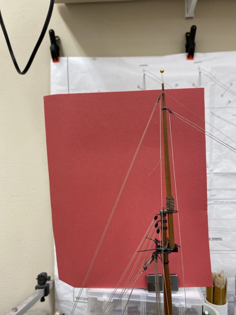
I rigged the other side of my test mast using the .015 line from the kit painted grey using Badger grey primer. It dries really quickly so it is easy to "make more" as I need it. As I suspected it is easier to get the steps to "stick" on the rougher painted line than with the nylon coated wire so I am going to go with the painted line for the standing rigging. Here is my test mast with six steps installed. I am going to stick with the music wire for every fifth line but am going to paint it black before installing.

- 144 replies
-
- 2
-
-
- charles p notman
- finished
- (and 1 more)
-
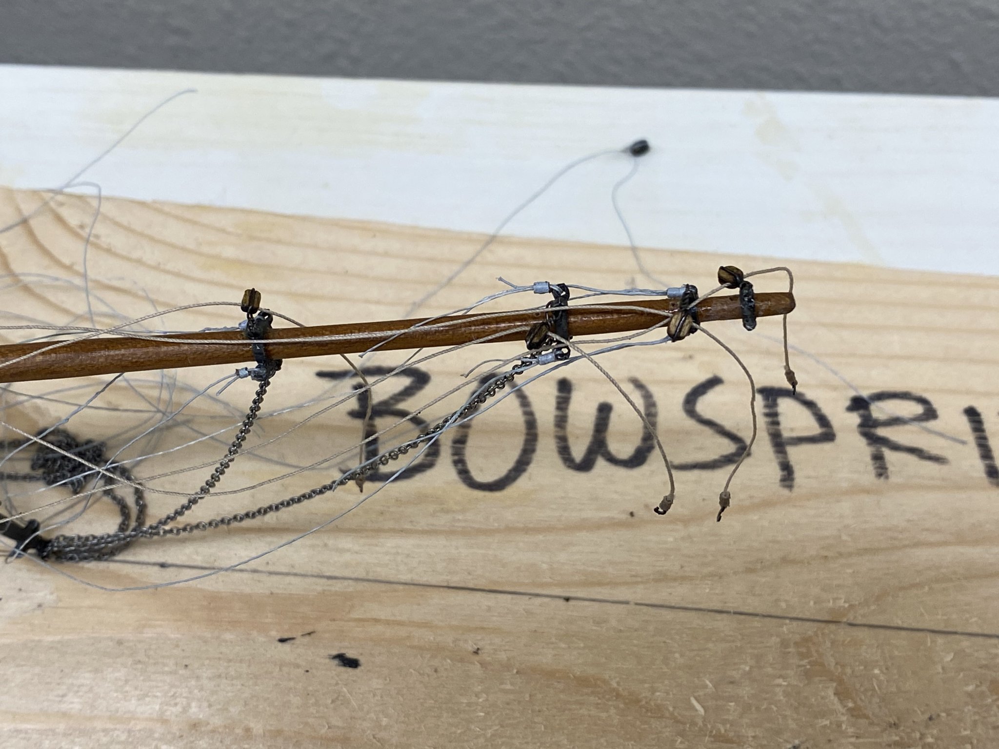
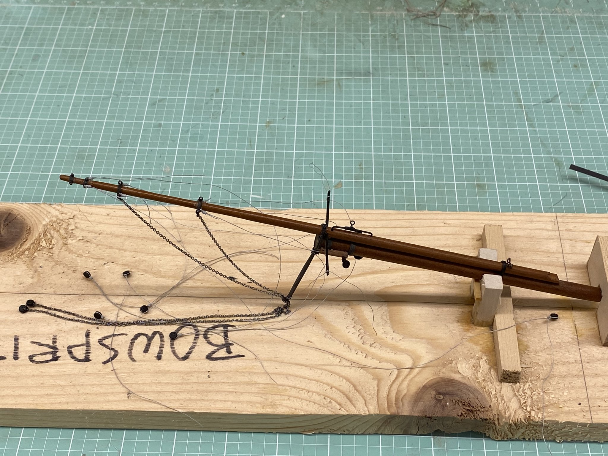
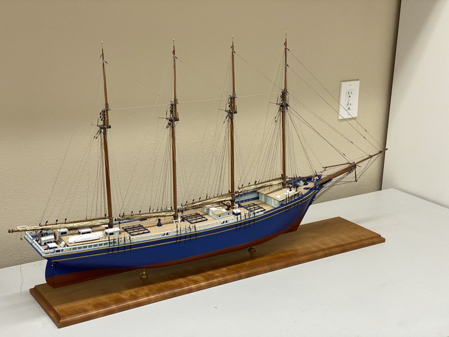
So here she is mounted on the display board. I am going to tape some paper over the finished board "just in case". After looking over the rigging scheme again I decided that trying to reeve the line through the 1/8" double block for the Jib sheet when it is stuck between the knightshead and the splash rail would probably require more dexterity than I have. So I rigged the tackle and will attach the sheet block to the boom for the jib when that is installed (which will be pretty soon now). Here is the tackle waiting for its "moment in the sun". I managed to get the two forward sections of chain on the dolphin striker and am setting up the deadeyes on the bowsprit now. I decided that 3/32" deadeyes are just too small for me to deal with so I am using 1/8" walnut deadeyes painted black. If I used the provided Britannia metal deadeyes I would have chemically blackened them so that is why I chose black paint. Here is the bowsprit/jib boom as it stands - before I painted the deadeyes. The next step would be to rig the bowsprit/jib boom back stays. Which leads to my next decision. I had decided to use the Beadalon silver wire instead of the provided line (painted gray). After dealing with the wire on my "practice" shrouds I am beginning to question that decision. The Beadalon looks great but, unlike the line, it has essentially no inherent stretch and the nylon coating is pretty smooth and difficult to get even the Weld Bond glue to stick. A smooth surface will not be an issue with the painted line and I believe there will still be some stretch even after the paint dries. I have decided to rig the other side of my test mast with the recommend .015 painted line from the kit. I am still going to use the .010 music wire for the long foot ropes as I did with the Beadalon and will add some black steps to see if it is any easier. I need to decide whether or not to use the Beadalon now since the bowsprit/jib boom back stays are wire and they are "next up".


- 144 replies
-
- 3
-
-
- charles p notman
- finished
- (and 1 more)
-
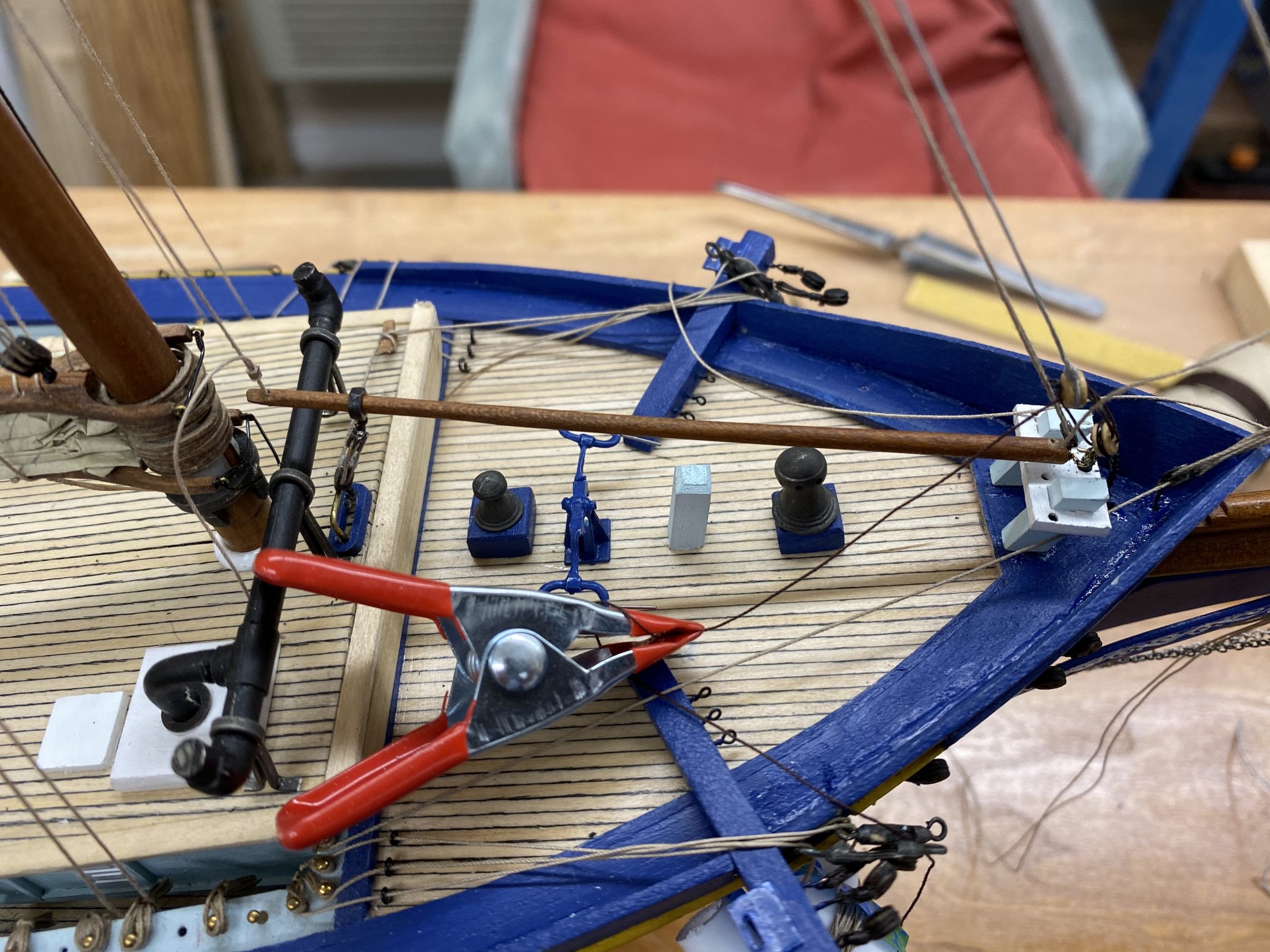
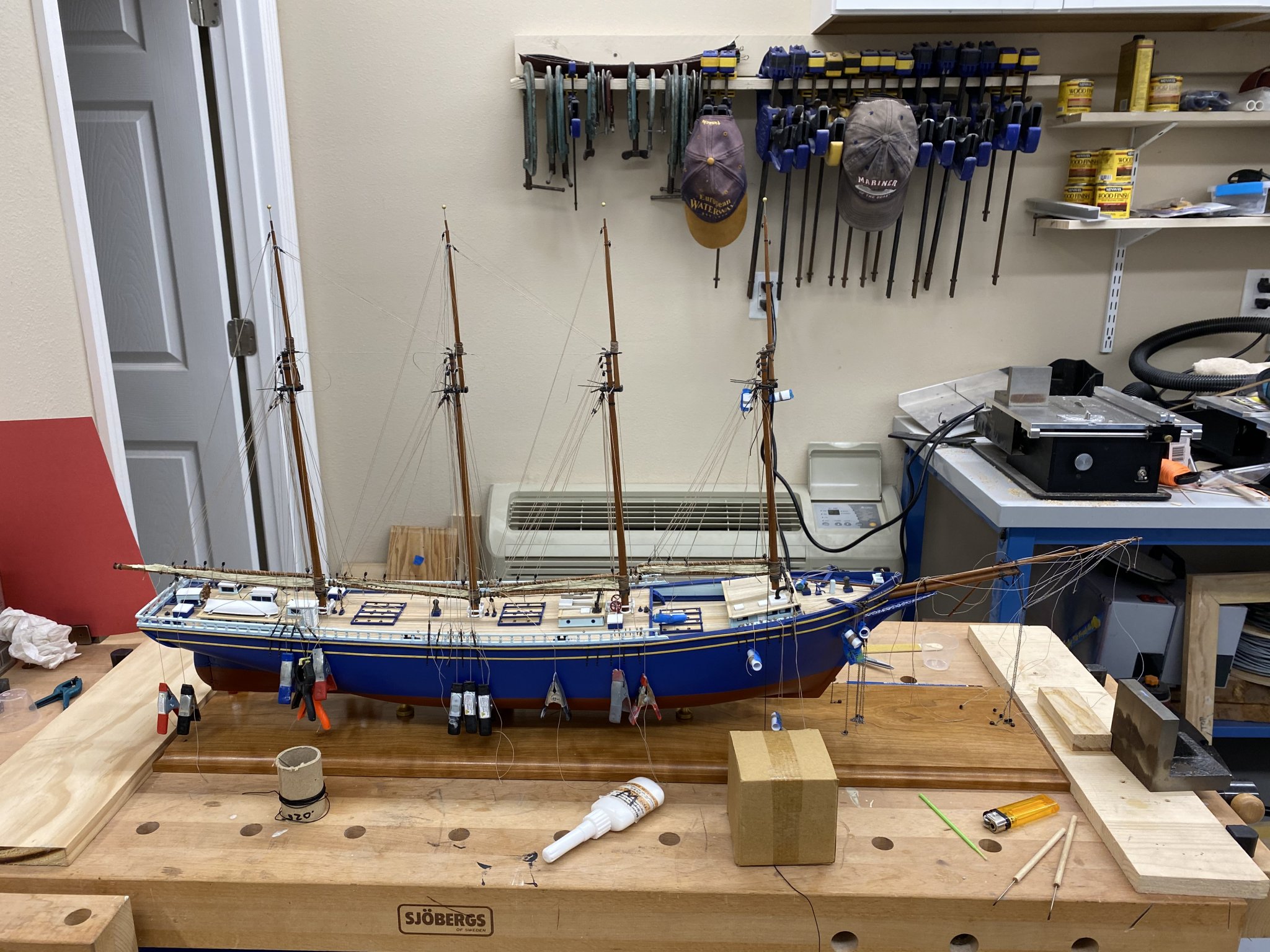
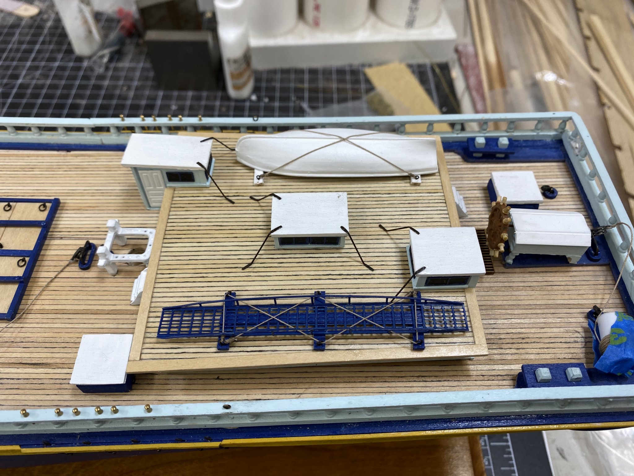
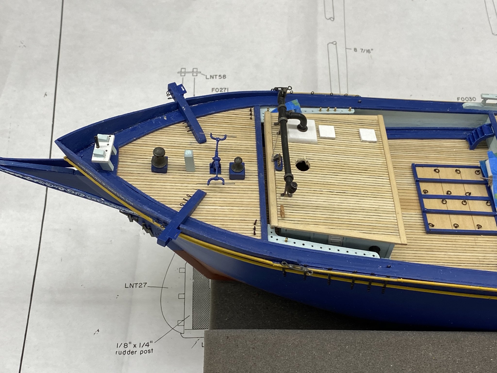
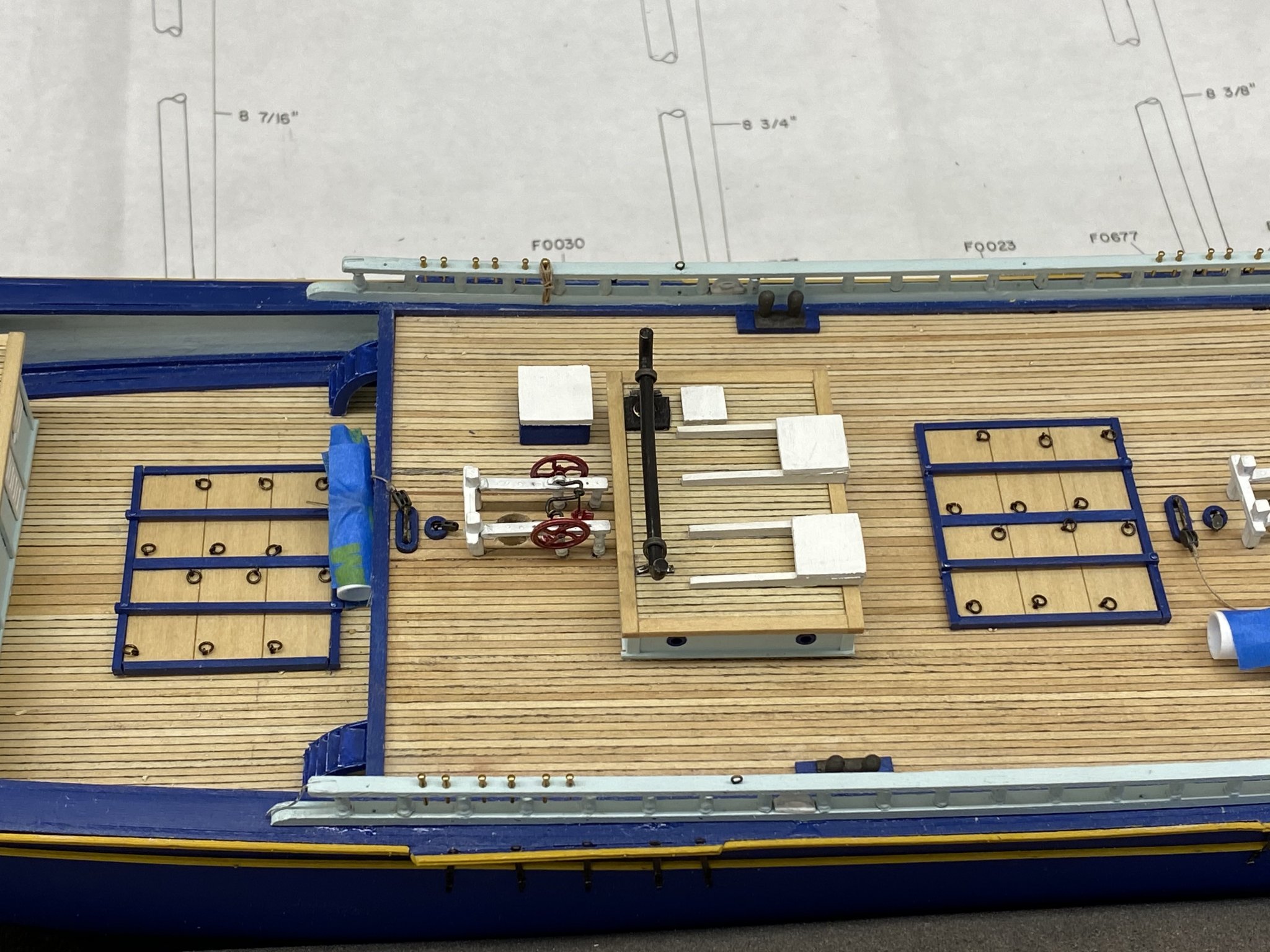
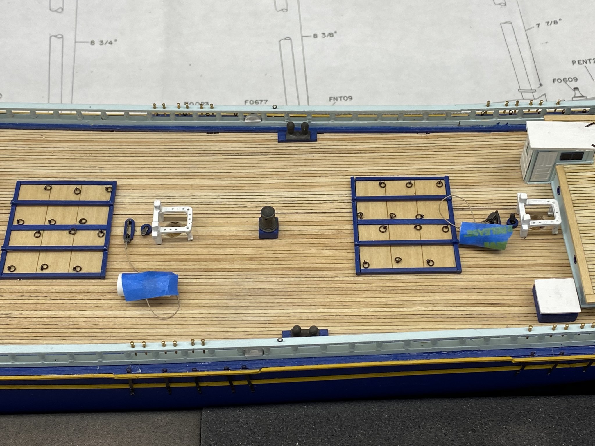
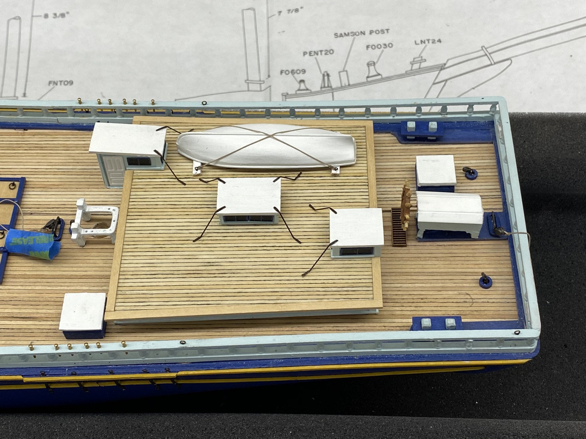
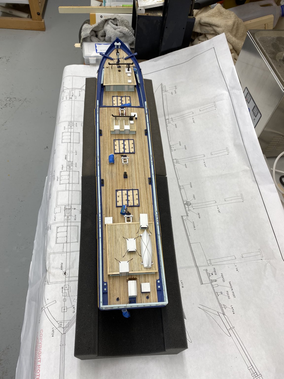
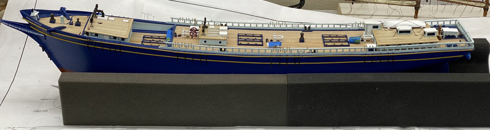
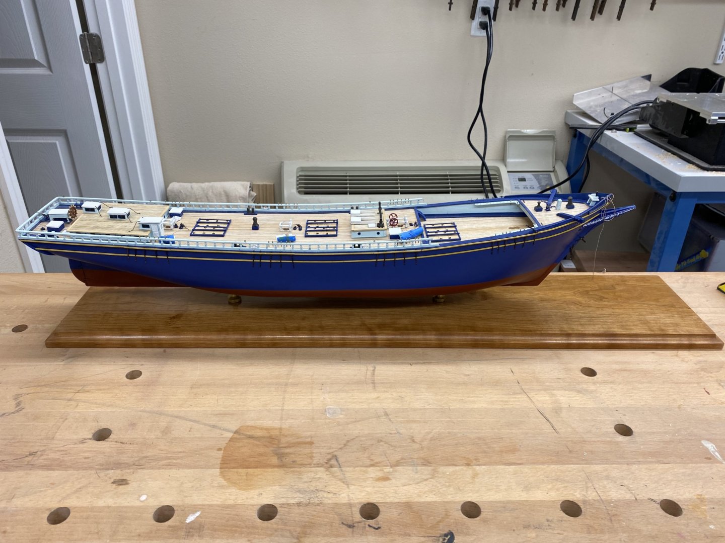
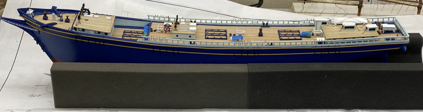
It is time to "put it all together". I went from drawing to drawing and page to page in the instructions to get everything where it belongs. Here is the fore deck - per the instructions the forward deck house is not secured yet - need to get Fore Mast in place first. The drawings show what In assume to be two capstan bars secured to the deck (one on each side also my assumption) but no mention of them in the instructions or anywhere else. I will think about adding them - maybe. The fife rails (also per the instructions) are not secured yet either, just sitting in the holes. Speaking of file rails, on the Mizzen and Spanker I ground off the pins on the after supports. It is hard getting all the holes in exactly the right place - if the large holes on the forward end aren't enough to secure them then I will have to live with the consequences. FYI - the things with blue tape on them are the lines attached to the sheet block beckets. Easier to keep them out of the way - sort of. Here is the rest of the main deck and the midships house. I have one rope coil on a pin as a test - I think that will do. Here is the rest of the poop deck forward of the aft house. And here is the aft deck house. I decided to put the yawl on top of the aft house instead of on the davits. I am telling myself that someday I will build a "proper" yawl for this model. I am waiting for a tool to help bend the accommodation ladder - I do not want to attempt that with just pliers. It will be on this side of the aft house, painted dark blue like the hull. Here are two shots of the entire topsides I am going to mount the model on the final display board when the last coat of WOP in dry - tomorrow morning just to be on the safe side (I applied it just before lunch). Next I am going to try and add some of the rigging to the bowsprit/jib boom before I start putting the masts aboard. Instructions say to start with the Mizzen - no explanation of why and I can't find where it says which to do next.


- 144 replies
-
- 6
-
-
- charles p notman
- finished
- (and 1 more)