


gieb8688
-
Posts
118 -
Joined
-
Last visited
Reputation Activity
-
 gieb8688 reacted to michael101 in HMS Victory by michael101 - Caldercraft - Scale 1:72
Hello friends, Here is a little update
First I’m posting some pictures of the process , Then I’ll post pictures of the currently stage ...
-
gieb8688 reacted to michael101 in HMS Victory by michael101 - Caldercraft - Scale 1:72
I just took the clamps out : i just notice that the lime wood has difrent colors as you can see in the picture but anyway it will be cover by the secound plank
-
gieb8688 reacted to michael101 in HMS Victory by michael101 - Caldercraft - Scale 1:72
and here is some planks that I have install until now (it take me 1 plank per day )
-
gieb8688 reacted to michael101 in HMS Victory by michael101 - Caldercraft - Scale 1:72
Hello Friends
here is a little update like I said before everything taking me a long time due to a lot of hours at the office
first I will start with a little trick for the fan method I got an idea to roll the fan printed at some toothpick
and it working great you can finde the distance between the belts lines very quick by rolling up or down the toothpick :
I also recommending when you using the fan method don't mark all the belts !! just the first one that you going to start with!
because sometime you can pass the line of the belt then you will need to calculate all the rest again ...
just finish the first one then after planking you can calculate the second belt act...
-
gieb8688 reacted to michael101 in HMS Victory by michael101 - Caldercraft - Scale 1:72
A little update
I have finish the lining the belts process
everything taking me long time due to a lot of work at the office ....
but in Hebrew we say Measured steps will lead you to a safe way
Regards,
Michael.
-
gieb8688 reacted to Peterhudson in HMS DIANA by Peterhudson - Caldercraft - 1:64 Scale
Update. Not much to add really. I have had a free morning so finished the majority of the upper section of the second planking in boxwood on both sides. I will do the quarterdeck and the trimming around the transom area later. I then cracked on with some walnut planning on the hull that will be below the waterline and will eventually be covered by copper tiles. My planking is not great so I am using this to get practice and improve even though my labours will be masked in due course. I think this phase might take some time!
-
gieb8688 reacted to kees de mol in Wilhelmina VII (KW140) 1914 by kees de mol - Scale 1/25 - Herring Lugger
New progress on the herringlugger. I started to finish the outside of the hull with thousands of 'fake' rivets. For these rivets I used some glue or paint for clothes. I also gave the hull a solid layer of primer to seal the rivets. In reality the ship would have more, much more rivets but I keep it this way. Iam afraid more rivets will do more harm then good. Now I have the idea off a riveted hull without turning it into a hedgehog or something.
I am also starting to sealize that this ship take much more time than the smaller models that i built earlier. It seems like evything takes twice as much time. But fortunately the challenge remains great and I enjoy the building of the model and the thinking out of everything.
Thanks for watching, commenting and hitting the like button.
(Updates will take a bit longer in the future. After working as a volunteer now since January with elderly people with dementia, I got a job as a student nurse at a big healthcare organization. This after more than six years of being not capable of working because of my bad health. The training will start in february. I thank my wife, my friends and God (and offcoarse the elderly people for stealing my heart😍) for these opportunities after so long being sick)
-
gieb8688 reacted to greenstone in AVOS 1806 by greenstone - Master Korabel - 1/72 - Russian Tender - test build
Here it is!
The first BOX of the new our kit "Tender AVOS".
-
gieb8688 reacted to greenstone in AVOS 1806 by greenstone - Master Korabel - 1/72 - Russian Tender - test build
For your attention photos of the model of the tender "AVOS"
with the first control assembly of our new model a 4-oared yawl (lenght -68mm, width - 22mm )
-
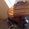 gieb8688 got a reaction from Heinz6672 in HMS Victory by gieb8688 - Sergal - 1/78 - Restoration
Finally finished the ratlines on the starboard side. Purists would be able to point out errors, but I am happy with the results. Also added some additional running rigging in the bowsprit area. Now on to the port ratlines!
-
gieb8688 reacted to Salty Dog in HMS HOOD by Salty Dog - Trumpeter - 1/200 - PLASTIC - w/Pontos PE
Hello all,
I just put one of the most difficult, most fidgety things you will ever do with PE. I had to take a break because I thought I would explode because I have to make another one! The PE is so incredibly fragile that just breathing on it just about bends it! (exaggerating). There is hardly any surface contact at all. Now, back to the next one
-
gieb8688 reacted to Salty Dog in IJN Mikasa by Salty Dog - FINISHED - Wave Models - 1/200 - PLASTIC - W/Pontos PE
And....it's done! Worked on the placard today. Wanted it to match the base with the faux marble. Trimmed lose ends. Replace the boats that "fit". After adding some of the rigging, not all fit. They barely fit even without the rigging. Lots of things getting in the way. The boats smashed up against the superstructure, etc.
The glass was a "pane". You really need to do all your calculations right. Then gluing it is very stressful. Typical glass cutters don't care about precision. They're used to cutting window glass that can be off by at least 1/8! I had to go back a couple of times. Finally got it as right as I can get. I love it! I've carried it around several times and it feels nice and solid. I had planned to add some angle stock to the corners and edges for support but it's totally unnecessary. Cleaning the silicone afterward was a nightmare!
The base is totally non traditional to say the least. But since the model itself, with the unpainted PE is non traditional, I decided to keep it that way. I Like it. Hope you do too. The pedestals were solid brass drawer pulls haha. Again, I like them.
I really loved working with the E Z line. Can't say how many times I snagged a line by accident and it just stretched....and stretched... and never popped off. Had it been typical line like on one of my wooden ships, it would have been a disaster. For such tiny scales, I think this stuff is the answer. Obviously, if I needed something "rope like", this would be out of the question.
Anyway, I plan and taking better photographs later, but here are these for now. IT'S DONE!!!
-
gieb8688 reacted to Salty Dog in IJN Mikasa by Salty Dog - FINISHED - Wave Models - 1/200 - PLASTIC - W/Pontos PE
Current status.
-
gieb8688 reacted to Salty Dog in IJN Mikasa by Salty Dog - FINISHED - Wave Models - 1/200 - PLASTIC - W/Pontos PE
Hello all,
I began this build about a year ago. I took several pictures during the progress of the build. Although it was not a true "log", it will show how it came along. I started a log on "another" website, and got very little interest, so I gave up.
Recently I was looking at some of the ship builds here, and found CDW's Mikasa Log. He inspired me to continue on my Mikasa with his very detailed log. He was very helpful with some rigging tips and I posted some of my own rigging attempts. I figured I was hijacking his build log, so this is why I'm doing this.
I hope you all enjoy what I've come up with. I decided NOT to paint the PE. I have built several kits with PE, and those that I painted, lost all the detail, all the wonderful, beautiful photo etch work that went on. The amount of work and incredible dedication that it takes to install this stuff, in my opinion, dims when it's painted. The pretty gold color of the brass is like jewelry. Even those that couldn't care less about a model ship, are drawn to it with "ooohs and ahhhs".
I also like to mess around with my own colors. I just can't see making a bunch of gray ships that look like floating penitentiaries. So some might be highly offended by my interpretations. Sorry. Life's too short and I'm having fun.
So here we go...
-
gieb8688 reacted to Snow in Diana by Snow - FINISHED - OcCre
Hi guys after 17 months she is all finished
Oh what a journey and great fun its almost a shame to be finished but onwards now to the vanguard or maybe bellaphoran she has been sitting on the table for 4 months
Thanks all for your help
Cheers snowy
-
gieb8688 reacted to ESF in Zebulon B Vance by ESF - FINISHED - Dean's Marine - 1:96 - PLASTIC - RADIO
To those who gave likes, thank you and thanks for stopping by.
Bill and Ben, thanks for your feedback. Bows forward, probably with rudder/tillers laying on the thwarts.
Carl, your wish is my command.
Denis, thanks for your kind comments.
Steve
A milestone day
Tonight marks the completion of all forward, aft and starboard railings, except for paint touchups and some final alignment tweaks. Thanks to everyone who offered guidance, feedback, and encouragement. Celebratory photos follow.
Next up are starboard davits and boats. I should probably do the railing touchups first.
-
gieb8688 reacted to ESF in Zebulon B Vance by ESF - FINISHED - Dean's Marine - 1:96 - PLASTIC - RADIO
To those who gave likes, thank you and thanks for stopping by.
Carl, thanks for your insight. I cleaned the minimal flash off the cargo blocks and one side now has a coat of flat light gray paint - same color as decks.
Kevin, thanks for your kind comment. The next construction will be much smaller I assure you.
Bill, thanks for your feedback. I had the gray coat on the cargo blocks before I read your message. Below, courtesy of the National Archives, is a pic of the davit rigging from the Vance in her John J. Meany guise (they changed the name to Meany during her hospital duty, than back to Vance for war bride transport). I think my current configuration will give a reasonable representation of the rigging.
Steve
Since it is a Sunday afternoon and I just finished the permanent installation of the first batch of railings (top deck starboard, boat deck starboard) I thought I’d share some progress pics, tarted up with incomplete lifeboats for effect. It brings up a question - are lifeboats stored bow forward or aft? I'm guessing bow forward from the photo above, assuming the name was on the bow. And would the rudder/tiller be stored in the boat or in place (shipped?)? There's a fragile PE piece I'd just as soon leave in the boat if that would be acceptable protocol.
-
gieb8688 reacted to drobinson02199 in Cutty Sark by drobinson02199 - FINISHED - Mantua/Sergal - Scale 1:78
A progress report on the first planking. Going very smoothly so far. Using my steamer at the stern. Pictures below. I'm making slow progress as I am gluing the planks in segments to be sure of a good fit, and I'm letting the glue dry for each segment.
One thing I noticed reading ahead is that the frame ribs will all be removed above the decks. If you look at the picture of the deck, the bulkhead that will be left is very long, and I was concerned about its integrity. So I glued the planks not only to the frames, but to each other along the entire edge. I was only going to do the edge gluing for the portion above the deck, but have continued further it as it seems to produce a smoother hull.
This is the first time I've done the edge gluing, and I'll now always do it, but I'm curious if it's actually a standard first planking technique and I'm just catching up. Do others of you do that as "standard"?
Regards,
David
-
gieb8688 reacted to Kevin in St Nectan by Kevin - FINISHED - Mountfleet Models - 1/32 - Steam Trawler - Completed June 2020
Good evening everyone
the wheel house assembly continues, im determined this time to complete projects and report progress if anyone is interested, and not post other bits that i have started until relevant,
-
gieb8688 reacted to Kevin in St Nectan by Kevin - FINISHED - Mountfleet Models - 1/32 - Steam Trawler - Completed June 2020
few photos i took yesterday at the Warwick show, of the St Nectan and also ordered one
-
gieb8688 reacted to Jaeon in Phantom by Jaeon - FINISHED - Model Shipways - 1/96 - The 11 year Pilot boat project
I finished my Pilot boat. It took 11 years.
I had built many plastic plane models and felt it was time to try something new. My wife bought me this kit for Christmas 2007. I dug right in.
I followed the practicum as best as my ability allowed me to. I made small errors from the start. Small errors compound over time. If the templates are cut a little off the hull will be a little off and from there everything else is a little off til a point is reached where I said uh oh this is not going to fit there as it should.
I progressed well enough through coppering of the hull, etc. When the time came to craft the cap rail I had an extremely hard time of it for whatever reason. Nothing I did worked. Frustration set it.
I don't understand this. I had no desire to continue. I packed up the ship and put it in the closet. It sat for a couple years. Then, I needed closet space so the ship went to the garage attic where all things go to die. Over the next 5 years I saw it on occasion while looking for something else. On occasion my wife asked about the boat and I told her the truth....My skill level sucks, I have no desire, I can't understand the next step, etc. I don't lie to myself or my wife.
In early December 2017 I needed something to do. I was only working per diem and very near retirement. I rescued the Pilot boat. The cap rail was still a conundrum. I spent some time looking over what needing doing and figured a way. Balsa USA is in my town so I went over and got a couple sheets then traced and cut it out as one entire piece. I did that 4 times before I got one that worked to my satisfaction. I glued it down and didn't like it at all. I ended up removing it and trying again...finally ! I worked on the ship almost daily for four months. The good weather arrived and I put it away til December 2018. Since then I worked on it sporadically. Today I hung the last flag.
Rigging taught me that super glue is my friend. I learned that later then I would have liked. The rigging that came with the kit is not good. I would have bought aftermarket had I known it exists.
There is a lot more I could write and I may
-
gieb8688 reacted to schooner in SS Stephen Hopkins by schooner - FINISHED - BlueJacket Shipcrafters - Liberty Ship
Hatch Nr3 Rigging
This hatch, like the last 2 to still to come, is rigged as a “Burton” or “Yard and Stay,” rig which had several variations. This hatch is rigged as the “standard” type. What made these rigs interesting for me is that the booms do not move during the cargo operation; the cargo can be moved anywhere along a line connecting the 2 points directly under the end of each boom by coordinating the 2 cargo winches. In this case one boom is positioned directly over the center of the hatch and the other over the side of the ship for loading to/from a pier or lighter.
When I was onboard the SS John Brown in Baltimore they ran a demonstration of a yard and stay rig at work, pretty simple when you see it in operation but it took a lot of concentration by the winch operators and foreman, one missed signal and the winches could end up pulling against each other which would quickly collapse the whole rig, with all the expected death and destruction.
Here the 2 cargo whips are rigged together and secured to an eye pad near the hatch:
I had to install the life raft racks before rigging the guys to make sure there would be no interference. The racks are made up of 4 pieces of VERY thin laser cut wood. It was a little intimidating cutting them loose from their fret/billet but once they were glued up they are pretty sturdy:
Here is the final rigging, minus rope coils that will come later - it is starting to look pretty busy:
-
gieb8688 reacted to rwiederrich in Great Republic 1853 by rwiederrich - FINISHED - four masted extreme clipper
I added some coils around the anchors...another pic before I begin the shrouds.
-
gieb8688 reacted to Heinrich der Seefahrer in SAINT PHILIPPE 1693 by Heinrich der Seefahrer - Heller - 1:92 - converted from Soleil Royale kit
Here the pictues for the Ancre's plan drawing of the galion and the 70th imagination done on the Heller draft board. This is something I'll have to change, too.
-
gieb8688 reacted to Heinrich der Seefahrer in SAINT PHILIPPE 1693 by Heinrich der Seefahrer - Heller - 1:92 - converted from Soleil Royale kit
Hello yesterday I decided to try to act as a scientist...
I thought, if I get the inner form or the hull I could easily construct bulkheads to build an inner structure. But how to come to such an inner form? By using building foam!
So I painted the hull with oil closed the lower transom by the kitpart with tape and filled in foam...and I stoped at the line of the gundeck... I promice I did!
My idea is to cut the foamblock into slites to get my bulkheads, so I can copy them onto birchplywood and saw them out. This inner structure will hold the hole wight of the kit on its four point stand. So I bought threaded rod and drive-in-nuts (not: werft-mother, stupid Google 😉 ). So the Under-gundeck area is well connected to the hull, because this gluing-area takes all the comming wight of the hole SAINT PHILIPPE - from the masts to the gun barrels to the rigging and bolts and gratings been pulled and pushed into the kit.
And until I can open it I have to wait 24h ...
Under the transom on the edge of the lower transom part there the tape opend and foam got out and got aou and more... so I dont knor how the wood struchture under the foam on the outside of the kit looks like.
May be the solvend ruined the kit... but there will be a fat layer of antifouling paint - there is some hope left. So I may have god good luck in the middle of bad luck. We'll see in some days!