


wefalck
-
Posts
5,583 -
Joined
-
Last visited
Content Type
Profiles
Forums
Gallery
Events
Posts posted by wefalck
-
-
Thanks, gentlemen, for the encouraging comments.
As noted at the beginning, the model will be presented in scenic setting. The ‚story-board’ for this reads like this: a botter from Marken (around the late 1800s) got caught out by ice and made it only into the port of Volendam, where it is locked up now by a solid sheet of ice. It is Saturday afternoon. The crew keeps themselves occupied with some maintenance work, while some Volendammer folk enjoy the cold, but bright winter weather during a walk on the dyke or on the ice. This story was inspired by a winterly visit to the Zuiderzeemuseum in Enkhuizen followed by a drive along the dyke down to Volendam. The Ijsselmeer (then Zuiderzee) was covered in pack- and pancake-ice.
I don’t the traditional costume of the women of Marken aesthetically not so pleasing – they had their neck shaved, while long temple-locks dangled from underneath their coifs or caps. The costume of the Volendamm women- and men-folk on the other hand is what we consider ‚the’ traditional Dutch costume. Volendam actually is rather atypical, as it is a catholic ‚island’ in largely protestant surroundings. However, the pictoresque setting and people as well as increasingly easy accessebility resulted in many painters coming here, so that the Volendam images became icons of the Low Lands. Later, the Dutch tourist board and other marketing organisations perpetrated these images. The above story allows me to show the Marker botter (Volendam mainly used a slightly different variant of it, the kwak, and the Artitec prototype was a Marker botter) in a Volendam setting. The winter setting allows me also Breughel citations of winter pleasures, albeit in a more modern environment.
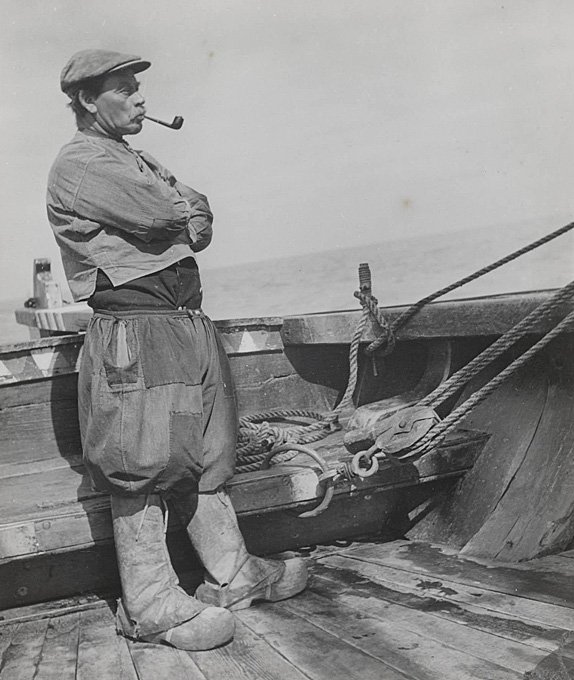
Marker master-fisherman (© www.geheugenvannederland.nl)
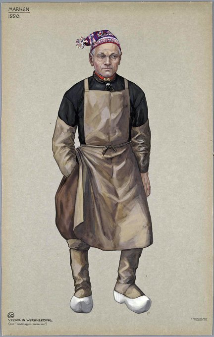
Marker mate (© www.geheugenvannederland.nl)
In between the work on the botter model, I turned my attention to the botter skipper and his mate. To this end I obtained second hand a set of Preiser-figurines (http://www-preiserfiguren.de) ‚Various Occupations’, from which I selected two suitable personages. These were carved and sculpted so represent Marker fishermen in their traditional work-a-day outfit. This outfit consist of woolen or linen culots, worn with long dark-blue stockings. The upper body is covered by dark, woolen shirt with a low upright collar or a turtle-neck sweater. Over this in the winter a short, spencer-type or a pea-jacket was worn in the winter seaason. The fishermen appear to have been a hardy species so that one doesn’t see jackets too often on winter-photographs. But they also had woolen underwear. The feet were protected by the iconic wooden clogs. The shape of the clogs varied from village to village. When working the net or doing other wet work, the lower leg were protected by gaiters that reached over the clogs. The characteristic male headgear in Marken was either a black, round (often rather battered) felt-hat or small black képi with a narrow shade.
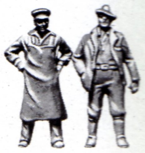
Scan of the Preiser box
The Preiser country-gentleman or whatever the figure in long boots is mutated into the skipper with the aid of a scalpel and putty. By the same method, an apron-clad drayman with a peaked cap mutated into a fisherman’s mate. The culots were sculpted using putty, while other features, such as shirt collars fell victim to the scalpel. The clogs also were sculpted in putty.
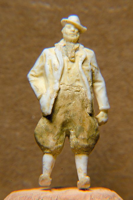
Fisherman ready to painted
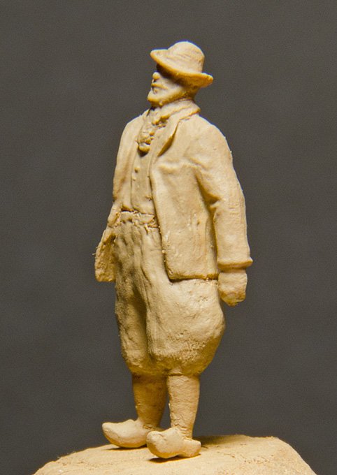
Fisherman after receiving a base-coat
I haven’t done any figure-modelling for years so my arsenal of materials was a bit limited: I just had a 40 year-old tube of Britfix ‚customising body putty’, which to my surprise still was useable. A 20 year-old pack of Milliput ‚grey’ was not quite so fit anymore. The base-coat in terracotta acrylic paint shows up all the places that need to be worked over again. However, remember this is 1/90 scale and the figures are just about 2 cm high and hence appear on the computer several times magnified.
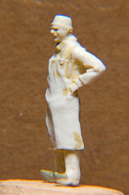
Fisherman’s mate ready to painted
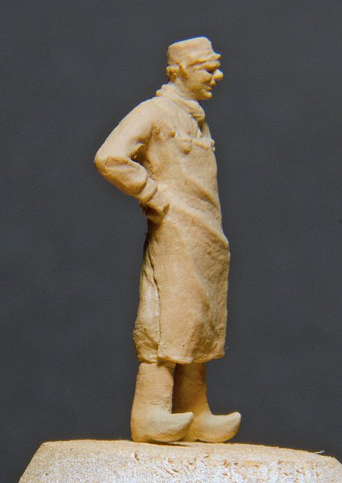
Fisherman’s mater after receiving a base-coat
To be continued with the actual paint-job.
wefalck
-
The work on the model is frequently being interrupted by travels and other activities, e.g. working up the pictures taken during my travels.It continued with the painting. The actual painting is a rather complex procedure and I have not documented all intermediary steps.
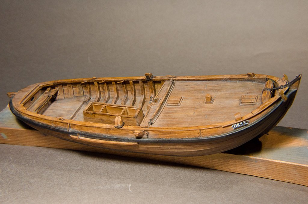 The first step after the base-coat was to apply a coat of nitrocellulose-based wood varnish in oak. The idea was to simulate to some extend the surface treatment of the real wood, though with somewhat different materials, in order to create ‚depth’ of the wood surface. I used this method successfully in the past on small parts. Here, however, the problem arose that a second coat or touching up would dissolve the first coat. On the next model I will apply the varnish by airbrush or use an acrylic varnish.
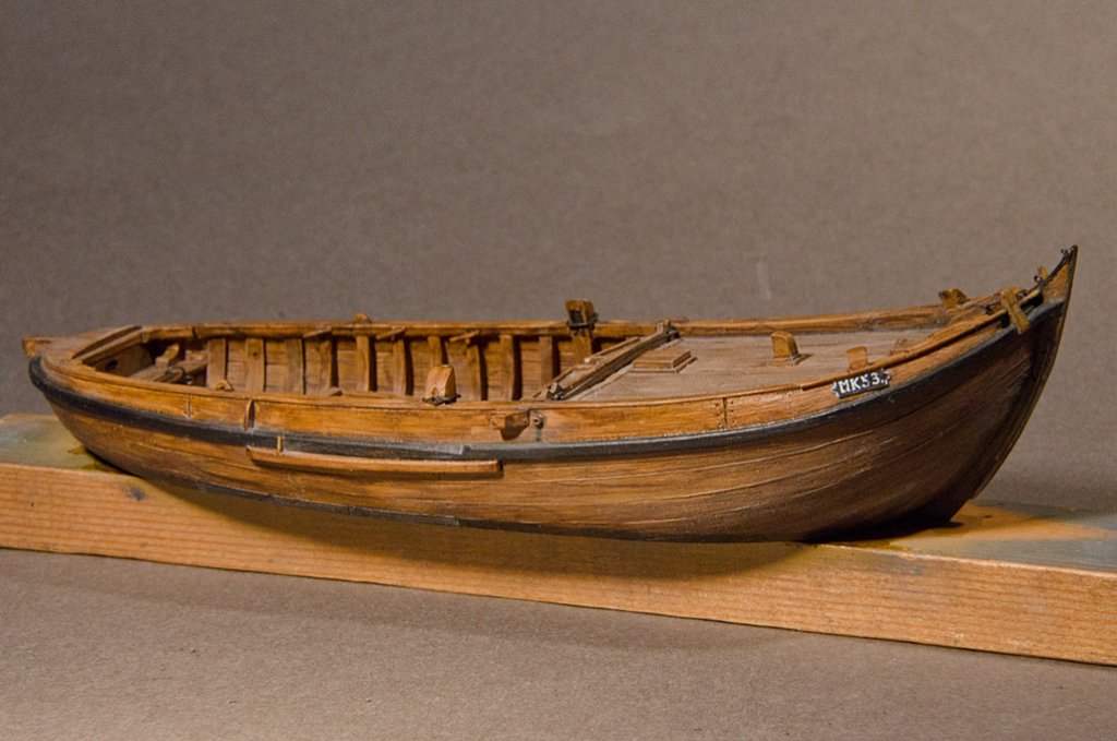 The varnish was cautiously matted with steelwool and a glas-eraser pen. Then the wale and the registration board were painted in black acrylic. The registration number was painted freehand in white acrylic. The next step then was a juidicious weathering/washing in burnt umber acrylic to simulate the surface treatment with Stockholm tar. In order to simulate the coal-tarred underwater body burnt umber was applied in more covering layers.
 Individual parts, such as the spars, the leeboards, the rudder etc. were treated in a similar way. In oder to achieve a uniform degree of matt-ness, everything was coated lightly with the airbrush in Winsor&Newton matte acrylic varnish.
 White, beige and black pastels were applied with a brush and Q-tips to simulate grime and salt. The quarter deck and floorboards also attain in this way a nice greyish worn appearance.
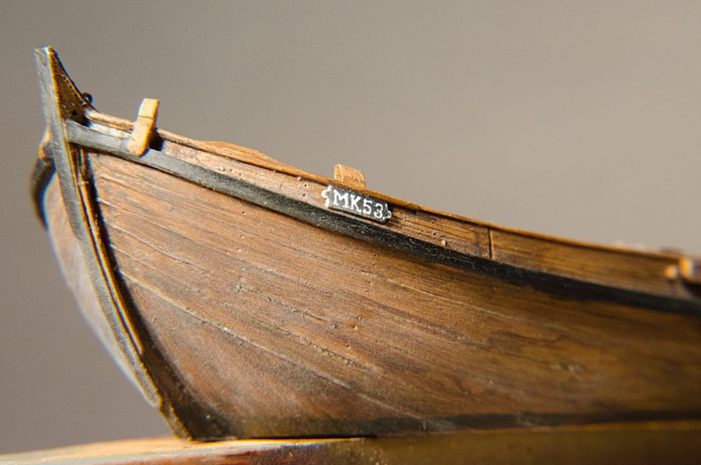 The various ‚ironwork’ received a base-coat in black acrylic with the airbrush. Then a mixture of ‚metallic rust’ (Prince-August Air/Vallejo) and burnt umber was then applied with a brush. The parts thus receive a certain patina – in real life they were painted black, painted in lineseed-oil or left bright. On places were the ironwork would have been bright from use a soft pencil (6B) was rubbed, which results in a subtle metallic sheen.
 wefalck
 -
I guess you are looking for end- or slotting mills. What widith is the slot ? End-mills at a reasonable price go down to 1 mm diameter, but are actually made for metal. There is a limit to the depth of the slot, as the end-mills usually have only a useable length of 3-4 times the diameter. There are also two-fluted carbide end-mills with a diamond cut at the sides, but I believe they are only made down to 2 mm diameter.
You would need an x-y-table to be able to do the milling. Pushing end-mills through by hand will sooner or later result in their breakage.
Another method would be to drill several holes along the slot and then to chisel out the material in between. You would need to grind your own chisel from a piece of tool steel or modify a small cheap screwdriver. The blade of the chisel should be the width of the slot.
wefalck
-
The classical surgical/laboratory stainless still is 18/8, which means 18% Cr and 8% Ni. The variant of steel alloys is legion and there are many more alloying metals in use, such as manganese (Cr-Mn-steels are in addition to Cr-Ni-steels used make armour plates for ships).
There are also Ni-Cr-alloys without iron, which are used e.g. as resistance wires and in electrical heaters. The wellknown miniaturist modeller Lloyd McCaffery swears by them for making standing rigging - they don't corrode and don't sag like copper.
The oxidation behaviour of copper alloys is quite complex and depends on the environmental conditions and the history of the oxidation process. So the effect of blackening agents is difficult to predict. However, the trades supporting sculptors working in bronze do know very well how to control the process of patination and there are textbooks and recipies available (also in the Internet).
Nickel silver (also called German Silver, Alpaka, Argentan, Maillechort) is an interesting material (60% Cu, 20% Ni, 20% Zn) that has similar machining properties to brass. Unfortunately for us modellers, it is not available in the same variety of shapes and sizes as brass. It would be very useful for parts that have to stay silvery. Otherwise it is used in large quantities industrally, mainly as the base metal for silver-plated cutlery. Because it tends to be harder than brass, very thin photoetched parts are often made from nickel silver rather than brass.
wefalck
-
Bronze is the 'unknown' for most of us. It falls between brass and copper in composition ...
Well, not exactly. Brass is an alloy of copper and zinc, while bronze is an allow of copper and tin. While brass usually only contains Cu and Zn in varying ratios (tombak is a high-Cu brass), bronze may have additional components, such as silicium (Si), aluminium (Al) or mangan (Mn) to enhance its corrosion resistance or its properties as bearing metal. In general, bronze typically is more corrosion resistant than brass, which is why it is used e.g. for propellers.
Hardening or annealing brass is just the reverse of that for steel: quenching it after heating will soften it, while letting it cool down slowly will harden it. Particularly bronze can be hardened by hammering (see bronze age weapons) or pressing it (the Austrians used hardened bronze for their guns, while everyone else switched to steel).
wefalck
-
Both, gravers and woodworking chisels/gouges, these day tend to made from HSS. The main difference is the cutting angle and the way how they are offered to the work. The cutting angle of gravers is about 45°, while that of woodworking tools is much smaller. Woodworking tools are offered to the work normally with the bevelled side towards the material, while gravers are used the other way round. In fact, the angle with which gravers are applied is similar to the clearance angle on a lathe tool. If one applies a graver to wood, there is a high risk that they dig in.
I am not a woodcarver, but noticed that gravers would be useful, when cleaning up convex surface, where it might be difficult to find the right angle for a wood chisel. With caution gravers can also be used as scrapers on wood. The more homogeneous a material is, the better it can be worked with a graver, so bone or ivory are good natural candidates, as are synthetic plastics.
Apart from diamond and square shaped gravers for lathe work (traditionally watchmakers mainly worked with gravers) I have engraving gravers of varying width.
It is important to have an absolute flat cutting face, which is not easy to maintain, when grinding/honing by hand. There are various devices on the market that are intended to keep the face flat on the stone or the diamond pad.
wefalck
-
Thanks for the kind comments. Actually the sails are rather stiff and water wouldn't do anything on them, as the tissue paper is now impragnated with varnish and covered in acrylic paint. On the other hand the original sails also would have been quite stiff, at least stiffer than untanned sails.
Now the building has progressed far enough to be able to apply a base-coat of paint. After some preliminary trials I decided on a light terracotta as a base-coat for the hull, while the spars were painted in ‚bois’ (i.e. wood, Prince August Air). On top os this oak-tinted varnish will be applied to give the ‚wood’, that in the original was painted with tar and harpeus (a mixture of wood-tar and lineseed oil), some depth. The different base-coat colours where chosen to differentiate between the different woods, i.e. oak for the hull and pine for the spars.
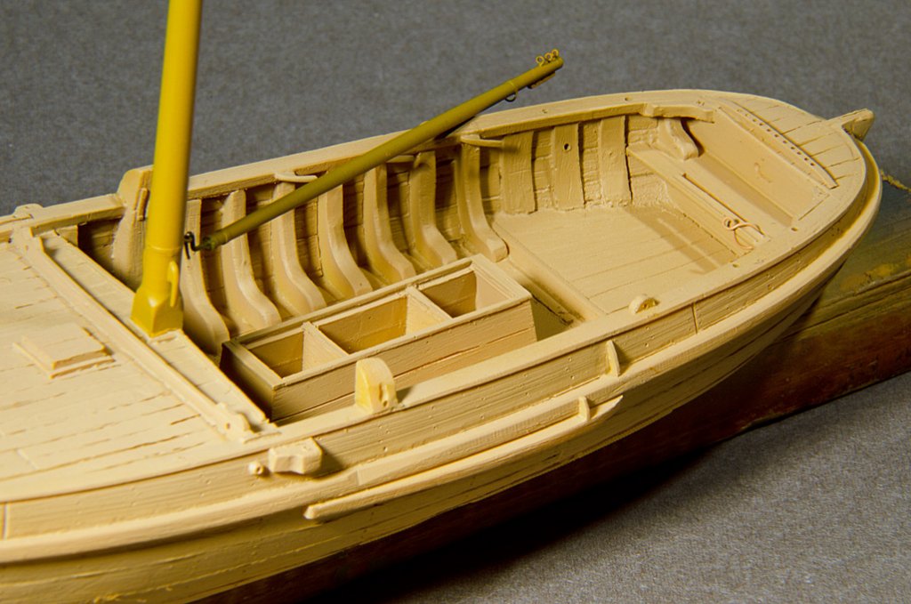
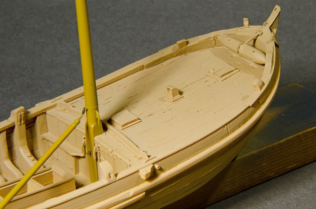 The matte base-coat makes visible the ‚rustique’ style of modelling by Artitec and also any imperfections in building. Photographic images even further enhance any imperfections that are not so obvious to the naked. There is a need to work over one or the other part.wefalck
 -
I think we are mixing here two issues, what was done in real life and what to do for models. Garward, you were talking about models, while dafi was talking about the real thing.
Yes, some of the 'quick blackening' agent contain selenous acid.
wefalck
-
Contemporary to whom ? To us or the time of the prototype ?
Actually, I don't think that bronze (not brass) guns where painted as the material is quite corrosion resistant and develops a protecting patina.
Cast iron and steel corrode differently, due to the graphite content in the former. I believe cast iron was often painted on an artificial patina. The controlled 'rusting' means a passivation and a better key for the paint than the bare iron.
When steel came into use in the second half of the 19th century, gun had become precision instruments that required a more controlled protection. The browing with vinegar etc. is not just throwing the acid over it, but it was applied carefully, sparing machined surfaces that had to retain their dimensions, such as seats for sightings, elevation mechanisms, or the rifling. However, some navies seem to have also painted their steel guns. In fact towards the end of the 19th century, when grey became ubiquitous, this became the general practice.
wefalck
-
Thanks for the praise

I am a bit apprehensive as to how they will stand up to being folded and crumpled when in a half-lowered state. As I said before, billowing or furled sails are not so much of challenge compared to limp ones, just hanging there to dry ...
wefalck
-
Don't know. Would depend on the brass. I also don't know what colour solid copper-acetate (which is what you probably would make) has.
To be on the safe side, I would use a commercial browning or blackening product. I do have an old-time recipe book for such concoctions used to create patinas, but in most countries, due to health and safety regulations, the chemicals needed cannot be obtained easily by private individuals anymore. In consequence the traditional technical chemist's stores have died out. You can also search the Internet for 'patina'.
I have not tried this on gun barrels, but a good way of simulating the 'browning' could be to chemically blacken the parts and then give them a wash in 'burnt umber' mixed with a drop of 'gun metal'. I have done this on black paint and it looks quite convincing. The chemical blackening also provides a good key for acrylic paints (if you don't touch it with greasy fingers).
wefalck
-
The vinegar for internal cleaning of brass and cast iron barrels was used to dissolve the residues of black powder. Normally, it was a three-stage procedure: vinegar, (sea)water, grease/tallow.
wefalck
-
Personally, I don't like sewn sails. Particularly the hems tend to be grossly out of size, as the cloth thickness is way overscale.
Anyway, if you do insist to sew, it is helpful to pin (or glue) the cloth down onto a piece of silk paper (the type used to make carbon copies in the age of the typewriter). This prevents the cloth from being pulled out of shape by the machine. It also facilitates sewing a predetermined path (not always straight for sails !), because you can draw the pattern on it. The paper can be ripped out easily after the sewing has been completed.
On the same line, I have simulated in the past boltropes by reducing the stitching step to almost zero, i.e. to the diameter of the thread, stitching effectively a beading onto the cloth. The sail was cut out after the paper backing hat been ripped out. The beading can be stabilised with a bit of clear varnish to prevent it from becoming undone.
wefalck
-
Frome a late 19th century German source for steel guns: rub down the barrel repeatedly with vinegar. Once a firmly attached brown iron-oxide layer has developed, paint in lineseed oil. To be rubbed down with a cloth soaked in lineseed oil for maintenance. Be sure not let the vinegare etc. into the barrel (particularly in the case of rifled barrels).
This seems to implicate that the barrels were of a satin brownish colour, which is also evidenced by contemporary paintings.
Cast iron guns, according to the same source were to be painted in oil paint.
wefalck
-
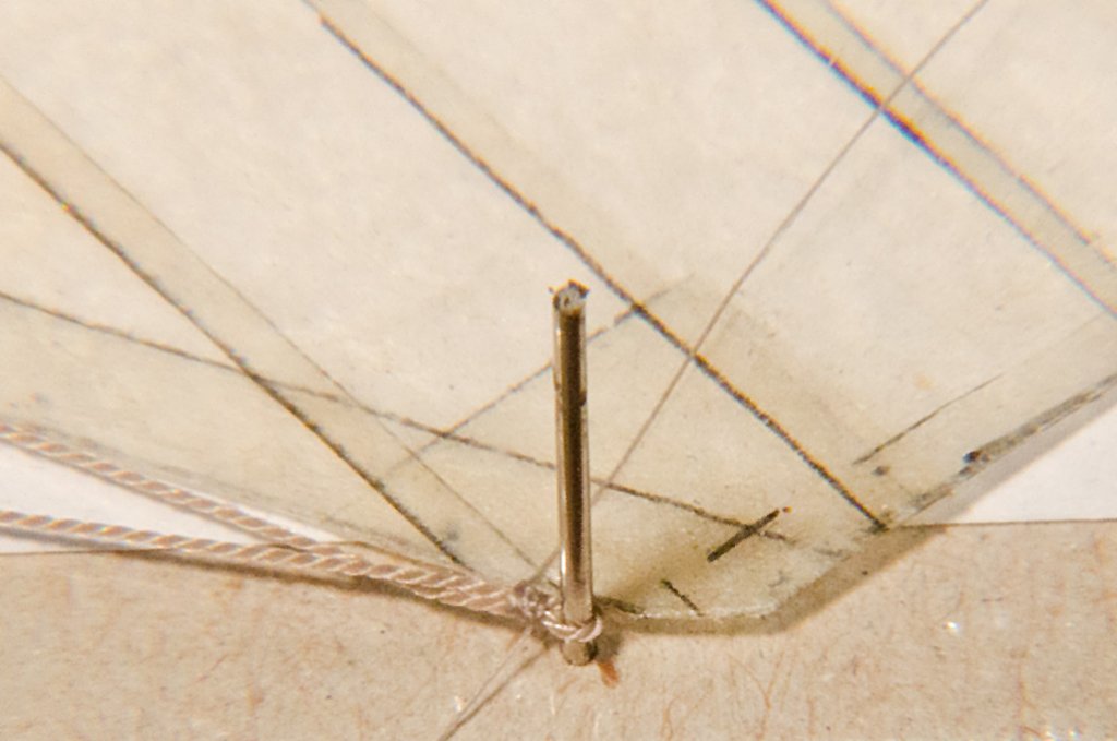
Continuation in small and sometimes tedious steps.The sails were further completed by adding cringles and eyelets. For the cringles the sail was punched with a needle to simulate the eyelets. A piece of 8/0 yarn was threaded through, twisted with itself and secured with a blob of lacquer. The free ends were threaded cross-wise through the second eyelet and secured with knots. The cringle was secured with a bit of lacquer. For eyelets in the sail itself blobs of acrylic gel were set on both sides and once dry punched with a needle.
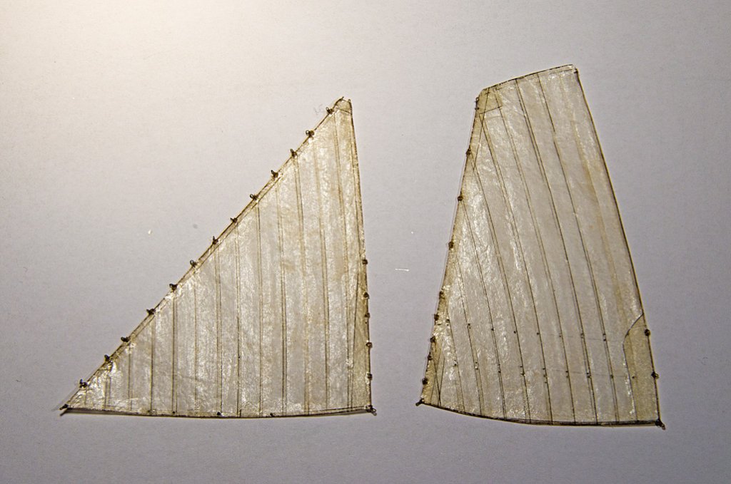 Sails ready to be paintedThe foresail runs on small iron hoops along the forestay. These were reproduced by small rings of copper wire that were sewn to the cringles using 16/0 size yarn (Veevus, http://veevus.dk]http://veevus.dk).
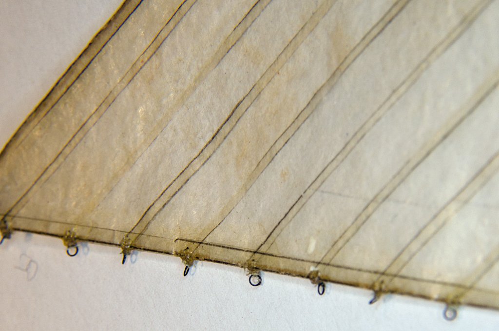 Hoops of the foresailsThere are various eyelets in the sail, e.g. for reefing points. These were immitated by a drop of acrylic gel medium glue on both sides of the sail that later was pierced with a needle.
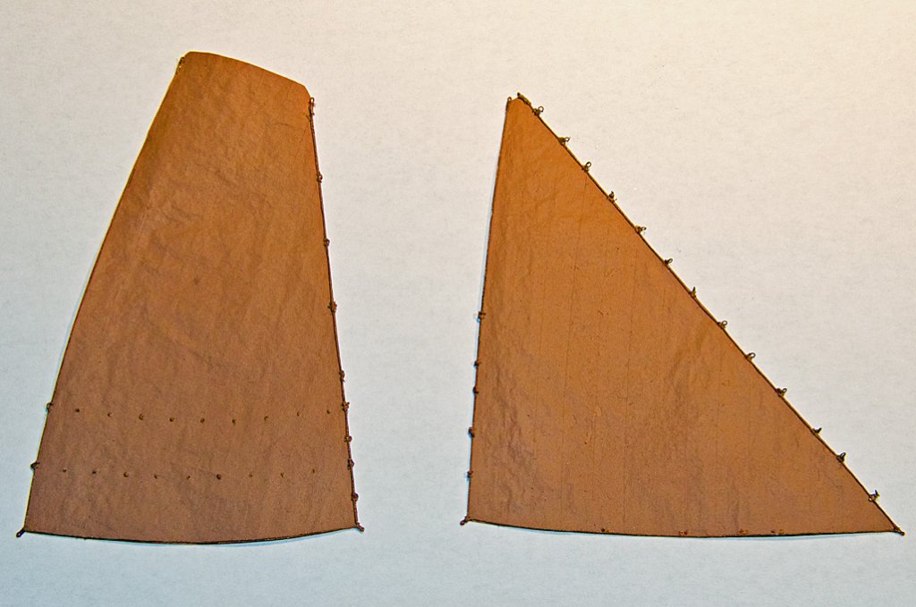 The painted sailsThe sails then were checked for any joints having come loose and more wood-filler was applied if needed. Now the sails were ready for painting. The original sails were tanned. Hence, a terracotta colour ('terre' by Prince August Air, http://www.prince-august.net) was chosen as the base colour that was applied with an airbrush. Once on the model some weathering and shading will add more plasticity. The eyelets etc. were ‚metallised’ by turning a soft lead pencil in them.
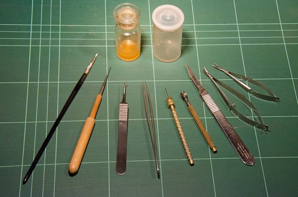 ’Sailmaking’ toolswefalck
 -
And the show continues ...
The next thing to go on was the bolt-rope. The rope was made on the miniature rope-walk from 8/0 size tan fly-tying yarn (UNI-Thread). According to the authors cited above, it was left to the individual sailmaker whether the bolt-rope was sewn to the port or starboard side of the sail. I attached all doublings to the port side and decided on the starboard side for the bolt-rope. Again it was glued on using the wood-filler.
Applying the bolt rope
On the prototype the bolt-rope does not continue all-around the sails, but rather ends at the respective head in spliced eyes. The mainsail is attached to corresponding eyebolts in the gaff with hooks or shackles in these eyes. Owing to the springiness of the fly-tying yarn, I found it impossible to recreate real eyesplices. I took some artisanal license and bound the eyes, pretending they were served eyesplices. The eyes at the other corners of the sails were fashioned in a similar way. To increase the stability of the sail, the corners of the bolt-rope were 'sewn' to the tissue paper using 14/0 size fly-tying yarn (Sheer).
Fake eyesplice
wefalck
-
We are metric here in Europe, so the mat has markings with 10 mm distance ...
Based on the information in BEYLEN and DORLEJN I made the individual cloths 6 mm wide (in 1/90 scale).
wefalck
-
First of all, thank you very much to all well-wishers

With many parts of the boat actually now completed, I turned my attention to the sails. I did this before painting the model, as various fitting and shaping actions will be required that may damage the paintwork.
The plan is to show the sails in a sort of semi-set stage, as they would be when the boat is in harbour, in order to allow them to dry. This going to be a much bigger challenge to represent convincingly than fully set or furled sails. As the boat will be shown in its winter rig, there will be only two sails.
The raw material is a very thin tissue paper that I found in my stock. The first step was to draw a sail plan 'as built', i.e. with the actual dimensions of the mast, boom and gaff.
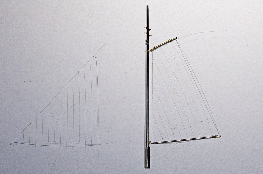
Sail-plan ‚as built’
Sail-plan ‚as built’ (detail)
The shape of each panel of sail-cloth was pencilled in also with the help of a french curve. The drawing then was backed with a piece of stiff cardboard and covered in clingfilm. Based on this pattern the individual sail-'cloths' were cut from the tissue paper with the addition of 1 mm for the seam. This is rather wide at this scale, but inconsequential as the sail will not be translucent, being tanned and dressed (i.e. soaked in a broth from bark and smeared with a concoction of tallow, oil and ochre) on the prototype. This treatment prevents the formation of mildew and permits one to furl the sails when still wet.
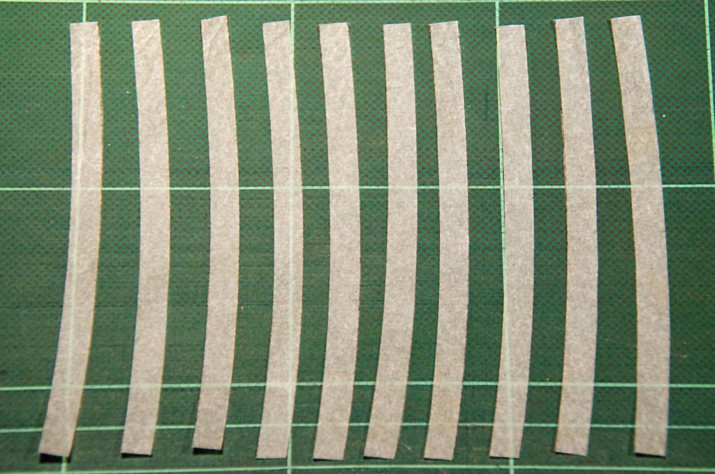
The ‚cloths’ of the mainsail.
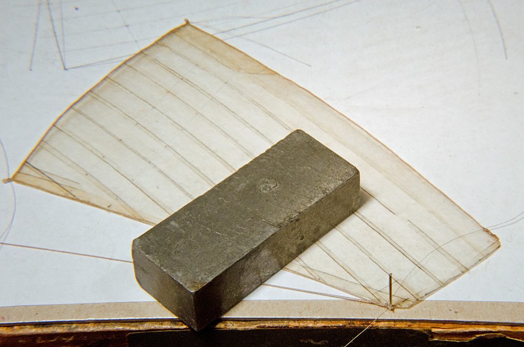
Using the drawing as a template, panels were stuck together using wood-filler (CLOU Schnellschleifgrundierung) as glue. The tissue paper soaks up the filler, turning it into a sort of compound material. I prefer wood-filler over diluted PVA-glue because it does not swell the paper and the joints can be loosened and re-adjusted by applying a drop of thinner. After completing the basic sails, outside margins and doublings were added in the same way, based on the detail drawings in VAN BEYLEN, (1995) and DORLEIJN (2001).
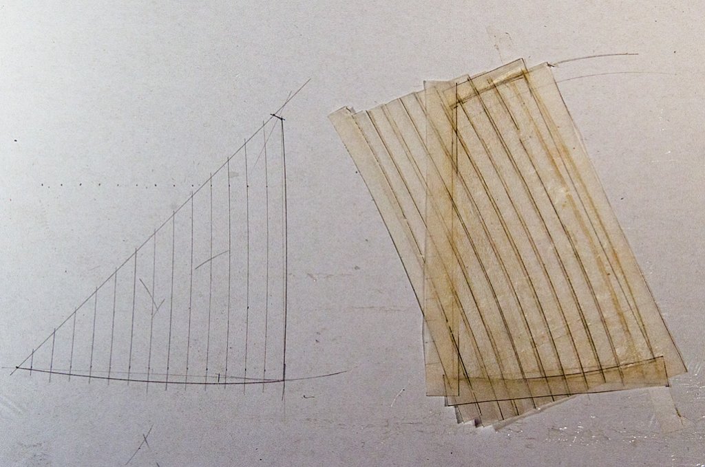
Glueing together the sail cloths
To be continued ...
wefalck
-
First I sand down these much to thick rings ...
Actually, depending on period and circumstances the hoops may not have been made from iron at all, but rather from split twigs of hazelnut or birch (I believe). There is a special technique to hook the ends together without nails or the likes. Such barrels would not contain any ironwork, but would be constructed entirely from wood. I have seen photographs of such barrels being made well into the 20th century, e.g. for shipping herring.
wefalck
-
Thanks, gentlemen, for the kind words. Back to the subject ...This building-log is a recreaction of the one started on MSW 1.0, so that the updates now may follow in short intervals, while the actual work was spread out over a considerable time. There were several delays due to some technical difficulties and the work was further delayed by some tool-making projects, numerous travels and too much work in general.I have been thinking very hard on ways to make really convincing rigging blocks of late 19th century model. Some of the blocks would have to be as small as 1.6 mm long, while the typical block would be just under 2 mm long. Most of the blocks would have to have external ironwork. The ropes for the running rigging typically would have a diameter of somewhere between 0.15 mm and 0.25 mm in 1/90 scale, depending on the particular rope. This would mean that quite a large number of holes of equivalent diameters would have to drilled to a depth of around 1 mm, which is a bit of a challenge. I wanted to avoid this by cutting slots into the material and inserting real sheaves turned from brass. The slots at the bottom would have to be filled in later.
 Shape-milling of blocks with a fly-cutter
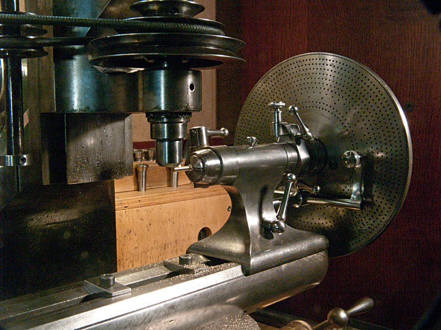 Set-up for shape-milling the blocks in a dividing head on the milling machineThe outside shape of the block was to be milled in the dividing head from round stock. A table was prepared that calculated the exact distance of the cutter from the centre-line for each pass, so that eventually the oval shape would emerge. This raw part then was transferred to the lathe for cutting the slots. While perhaps a good idea from a theoretical point of view, the slotted material proved to be too flimsy for further manipulation.
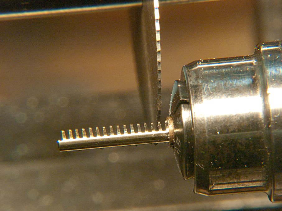 Slotting the blocks on the lathe
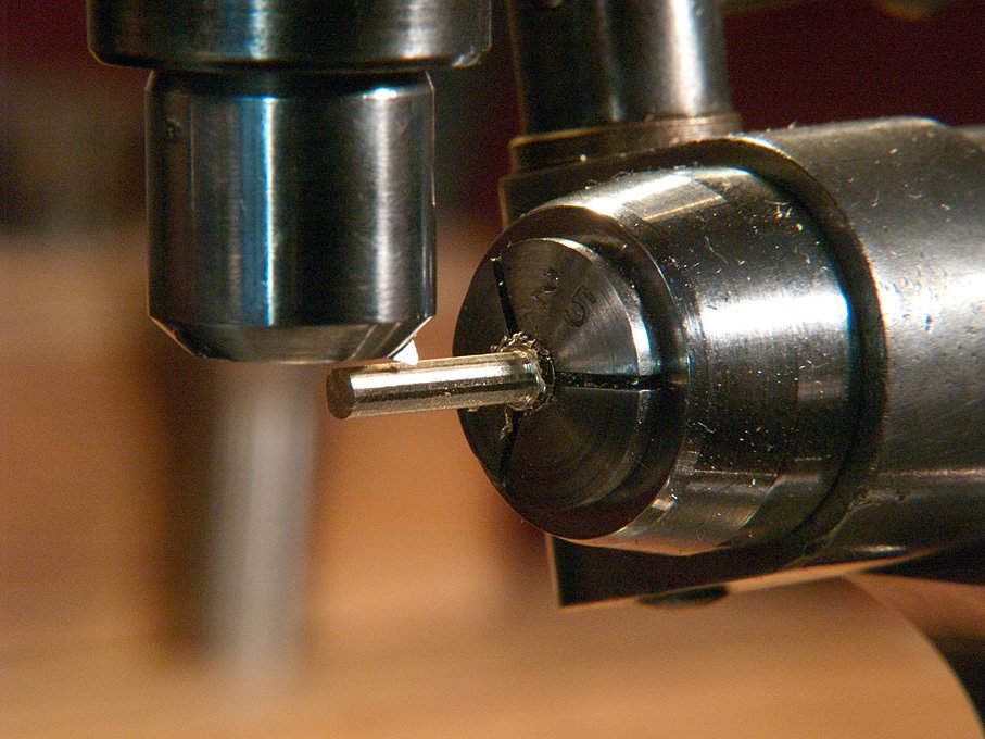
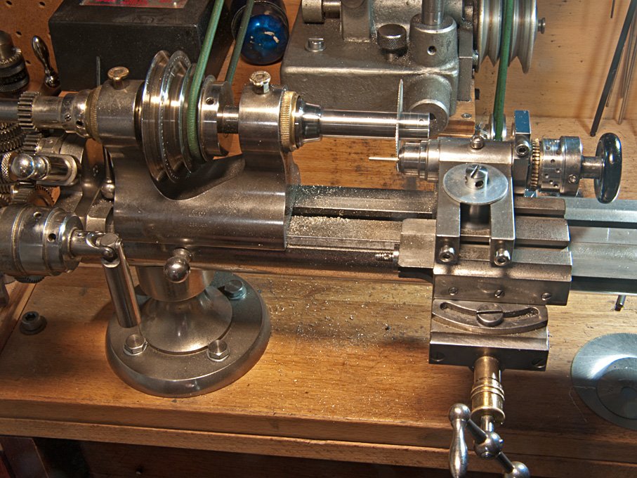 The set-up for slotting on the latheTherefore, a different method was devised, for which the material was changed from brass to Plexiglas. The outside shape was cut as before, but instead of using a flycutter, a dental burr was used, which due to its smaller diameter exerts less force on the part. Then the holes were drilled at pre-calculated positions. The cross-section of the future blocks were positioned in the round Plexiglas stock in a way that the axes of the sheave would coincide with the rotational axis of the dividing head. This arrangement allowed the sheave to be milled out of the solid. The holes then were drilled through with a miniature drill.
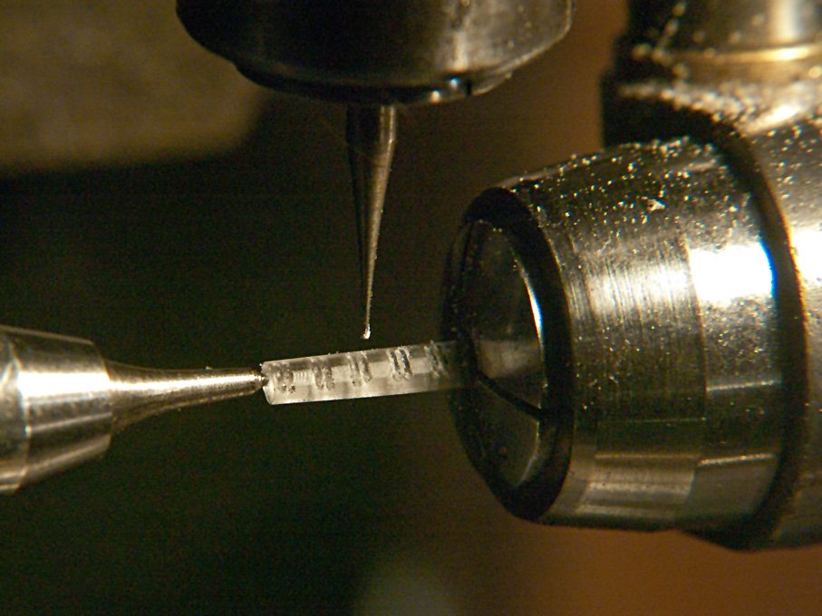 Milling of the sheaves from the solid stockMany shipmodellers just drill their blocks and perhaps, if they have a thin enough tool, attempt to file the edges of the hole round to give an indication of the sheave. However, this never looks quite right, with the ropes sort of sticking out sideways from the hole, rather than running around the sheave.These blocks then were cut off from the stock on the lathe. It should be noted that the stock was turned down at the end, so that it could be inserted into the collets against a shoulder, ensuring repeatable positioning. The latter was needed, as the dividing head on the lathe and the one on the mill use different types of collets.The botter has a variety of rather special blocks that also needed to be made, such as the sheepshead-block for the foresail. They were produced the technique described above, but in some instances were 'eyeballed' from the stock in the dividing head. One violin-block was also built up from hard paper with real brass sheaves and filed to shape by hand.The blocks were completed with 'ironwork' from copper wire. On the prototype this ironwork is forged from different sizes of bars. The blacksmith shapes the cross-sections as needed either flat (around the shell of the blocks) or round/oval for the hooks. This process was repeated up to a point by flattening the round copper wire used. In order to flatten the wire in a controllable and repeatable way another watch-repairing tool was adapted: a so-called jewelling press. This tool has a piston the movement of which is controlled by micrometer stop. In watchrepairing it is used to set bearings, i.e. the ‚stones’ or ‚rubies’ to an exact depth.I made some anvils and pistons for it that allow to squeeze the copper wire to a preset thickness over a particular length. The thickness is set with the help of a feeler-gauge.
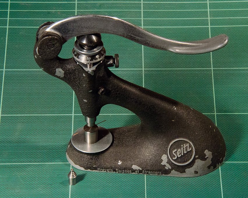 Jewelling tool with die for flattening wire
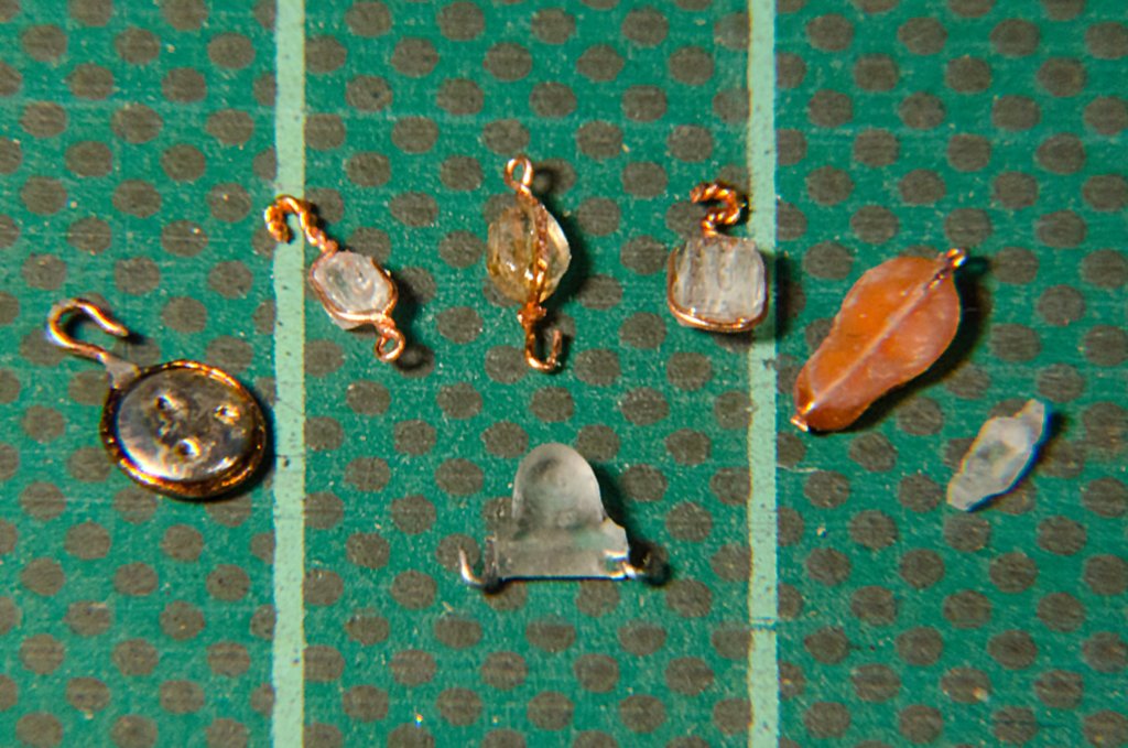 A selection of unpainted blocksThe results from all these labours are by no means perfect, but I think better than what I have seen around in this size.I am not certain, however, whether I would go down the same route again. It would be useful to be able to solder together the straps, which is out of question for blocks made from Plexiglas. Using hard paper/Pertinax would be an option, but drilling this material is not so easy, considering the small sizes of drills required. Perhaps one should use boxwood. In both cases round rods would have to produced first from the available stock. Or at least one would need to turn-on a round end, so that the stock can be taken into a collet – square collets for watchmaking lathes don’t exist ! (this is another of my future projects, to make a set of square-holed collets.wefalck
-
Jules van Beylen (I think he was the conservator at the museum in Antwerp) has written many books on Dutch/Flemish boats and ships. There is also a monograph on the hoogars:
BEYLEN, J. VAN (1978): De hoogaars, geschiedenis en bouw.- 184 p. (De Boer Maritiem).
Most of the books cited above are packed with drawings. Van Beylen's books are actually written for modellers and have very detailed description for building a model in a 1/20 scale. Full size drawings seem to be available separately. Dorleijn's book contains also folded plates, but seems to have become extremely expensive over the past. I have almost all of the books cited in my library.
wefalck
-
Yep, got a copy, but it doesn't have a date in int.
wefalck
-
Garward, liked your Estwing geologist's hammer ! Bought one like this in my first year at university ...
wefalck
-
Here a couple of interesting books on botters and boeiers, albeit in Dutch:
CRONE, G.C.E. (1926): Nederlandsche Jachten, Binnenschepen Visschersvaartuigen en daarmee Verwante kleine Zeeschepen 1650 -1900.- 309 p., 85 Abb., Amsterdam (Swets & Zeitlinger, Nachdr. 1978 bei Schiepers, Schiedam). - with English translations.
BEYLEN, J. VAN (1985): De botter - Geschiedenis en bouwbeschrijving van een Nederlands visserschip.- 223 p., Weesp (De Boer Maritiem).
DORLEIJN, P. (2001): De Bouwgeschiedenis van de Botter. Vierendertig voet in de kiel.- 168 p., Lelystad (Uitgeverij Van Wijnen ).
KAMPEN, H.C.A. VAN, KERSKEN, H. (1927): Schepen die Voorbijgaan. Een verzamling Afbeeldingen en Beschrijvingen die de Nederlandsche Binnenwateren bevaren.- 351 p., Amsterdam (A.N.W.B. Toeristenbond voor Nederland).
OSTROM, C. van (1988): Ronde en platbodems schepen en jachten.- 144 p., Alkmaar (De Alk b.v.).
SOPERS, P.J.V.M. (196?): Schepen die verdwijnen (bearbeitet von H.C.A. van Kampen).- 162 p., Amsterdam (P.N. Van Kampen & Zon).
VERMEER, J. (2004): De Boeier. – 528 p., Alkmaar (De Alk & Heijnen Watersport).
wefalck

Enamle vs Acrylic
in Painting, finishing and weathering products and techniques
Posted
What red do you use ? Some reds are made up from dyes, rather than pigments. So whatever you do, they are more washes than solid coats of paint. This is not a question of manufacturer or enamel vs. acrylic, but a question of the ingredients used.
wefalck