


wefalck
-
Posts
6,366 -
Joined
-
Last visited
Content Type
Profiles
Forums
Gallery
Events
Posts posted by wefalck
-
-
In order to answer your questions, one has to look at the 'construction' of ropes. Ropes are made from fibres that are spun into threads. These threads are gathered into strands. The strands are twisted against the 'lay' of the later rope so that they kind of wind around each other - this is what the ropewalk is for.
Sewing threads or crochet yarns may consist of two (typically) or more strands, but the strands are not as tightly twisted as in a ropewalk. Therefore, they cannot be used directly. If you chance upon a three-strand yarn, you can unravell it and then treat it in your rope walk.
The starting point for us are different 'sizes' of yarns. Each yarn will be come a strand, so each size only gives you one size of rope. If a given manufacturer offers only one size, you may have to look somewhere else.
If you twist together three ropes already produced in your ropewalk, you get a thicker rope - of course, but actually a different type of rope, a cable, i.e. a rope made of nine strands in groups of three.
Another version is the shroud-laid rope, which consists of four instead of three strands and is only used for specific purposes. On the prototype it would also have a core of a thinner rope.
-
I just take a brass or copper wire of suitable diameter and punch it flat at two points with a round, flat punch. I then lightly mark the centre in the flats and drill. The wire is then bent to the shackle shape around a pin nailed into a piece of wood. The shackle now can be cut off from the wire and both flat ends shaped with a fine grindstone in the hand-held electrical drill.
-
The wax is being printed, i.e. extruded hot from the printer's nozzle.
- jud, Bill Tuttle, Elijah and 1 other
-
 4
4
-
I would agree that our tools should be as aesthetic, as our products ...
- Canute, John Allen and moflea
-
3
-
On the prototype the rope would have an eye-splice in the end and would be attached to the block via a shackle. I don't know what scale your model is in or what lengths the blocks would have, but making shackles down to a length of 1.5 mm isn't too difficult. Likewise, it is quite easy to make 'false' eye-splices into the end of your rope using a sewing needle.
- mtaylor and Landlocked123
-
2
-
-
Harbours in the old days could become very congested with the often long waiting times to complete the loading. As yards were considerably longer than the width of the hull, at least the lower yards were lifted up at an angle in order not get entangled with neigbouring ship or harbour cranes etc. The universal joint would help in this. Before these forged universal joints were introduced in the late 1840s(?), the truss and parrel would have to be loosened for the purpose.
-
-
The mechanical point about the band-clamps (if you are referring to device that consits of four angles around which a string is lead and tigthened) that the resulting vector of force points to the centre of the workpiece, i.e. it pulls a frame or the side of a box together and also ensures that the corners are 90°. Now in the case of planking the question would be: do you see it running along the strake or perpendicular ? Running along the strake would not be useful unless you run the string over some piece of wood that are put perpendicular to the plank, so that you get a downward force. Winding your vessel with a string running perpendicular to the strake, on the other hand, might be useful to keep planks down. However, planks are often bend in two directions, i.e. not only along the strake, but also to follow upward sweeping curves. With just a string the latter might be difficult to achieve.
I frequently use band-clamps in making display cases for models.
-
-
-
Quite amazing, the animation ! I noted the same, that the change of hands during pulling isn't quite right, as there is a moment when no hand touches the rope, which would be physically impossible, the rope would drop immediately or run out.
-
-
-
Actually, I don't have an engineering background (I am a geologist) and no training as a mechanic ... I believe, that anyone, who can drill a hole into a piece of (ply)wood with reasonable accuracy and can saw-off a piece of steel or brass rod can build a rope-walk. It may not look as professional and may not last for decades, but it would serve the purpose.
Another route would be through an old Meccano set (or whatever construction set may have been available in your country). I vaguely remember that there was even an example in the booklet for my German Märklin construction set.
-
I have by no means a commercial connection with PROXXON ... I bought a PROXXON TBM in the early 1980s (and still have it and use it) and it has been for a long time my only stationary power-tool.
Soon after the purchase I slightly modified the fence, to that I could use it as an (inverted) router with the ubiquitous dental burrs with 2.45 mm shaft.
When I purchased it, they were also selling a kit for it, with which one could convert it into a simple (and somewhat wobbly) wood lathe; it had a face-plate, revolving centre, and a tool-rest as well as a longer pillar, which in fact I kept installed.
The face-plate, together with tool-rest (which has an adjustable fence) turned the machine also into a disc-sander. However, rather than using it with the face-plate I used it with a grinding-stone to grind the tools for my first watchmakers lathe.
As the head rotates around the pillar, one can also use it as a mobile pillar drill on oversize work, clamping it to the workpiece or the table for drilling outside the table.
So it was a worthwhile investment for a student and earned its life. Not sure, whether the current version of the TBM still can do all these things.
-
Small machines, such as the PROXXON TBM do not have Morse tapers. Their spindles are usually threaded on the outside for the drill-chuck and in the case of the PROXXON machines they also have a proprietary taper for collets that are tightened with a nut. Owing to the popularity of ER collets these days, you may also find machines with a taper for say ER11 collets (takes drills/end-mills/router bits of up to 7 mm diameter).
-
I think the original post was about dying wood black/dark brown, rather than giving it a antique look ...
These days I would give the wood repeated washes of black or brown acrylic paint. This is uncomplicated and dries fast.
The antique look is essentially simulating the grime accumulated in pores, crevices and nooks, which something different from a patina, which is the surface alteration of a metal under the influence of oxygen and other environmental agents. For the 'antiquing' you just brush on a dark permanent(!) ink or acrylic washes. Before the stuff is dry you can take some off again with a wet brush or you can wipe it off high parts. Doing it in stages, you can finely control the effect.
-
In principle, drill-chucks should not be used for milling, because they are not desgined for side-loads. However, when milling small pieces of wood, this may not be an issue. Having said that, you need a way to move the piece of wood in a controlled way. Normally, this is done with a cross-slide or -table.
You may, therefore, considering getting the small Proxxon KT70 cross-table for your drill press. Prices seem to vary quite a bit, but for about € 65 / USD 70 you should be able to find one. I seem to understand that you don't have the drill-press yet. If you get the PROXXON one, then it will have collets, which are just the thing for milling.
-
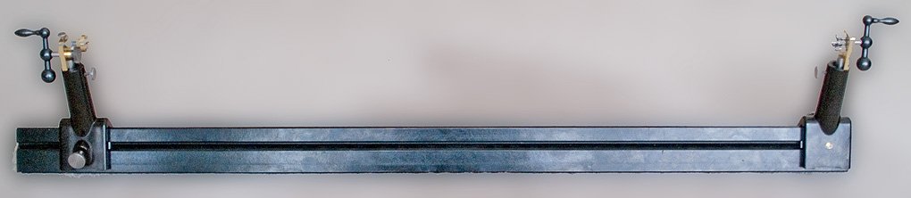
I think we have already several threads on the subject here. Somehow people seem to make a lot of fuss about these simple machines, while in reality it is easy to build one yourself with a saw and a (bench-)drill. Of course, one can add any kind of complications, such as an arrangement for continuous rope-making etc.
Until I inherited a nice 1940s bakelite optical bench from my father, I was thinking of using just simple curtain rails fixed to a plank of wood. Gears, steel rods, set-collars and other hardware you get either in a hobby-shop or DIY-store. Be inventive and make a simple design to suit the tools and skills you have. A simple sketch is sufficient as instruction.
If you apply the 'Frölich'-design, you can do away even with the dolly.
My design, using Frölich's idea can be seen here: http://www.maritima-et-mechanika.org/maritime/tips/Ropewalk/Ropewalk.html
- Canute, mtaylor and aviaamator
-
3
-
I use the same procedure as Dan and never injured myself in 30+ years ... Fear makes your movements unsure
")
Doctors and nurses uses such removal devices because they handle the equipment with surgical gloves that may not be perforated in order to remain sterile and in order to minimise the risk of infecting themselves by contaminated blood etc.
- mtaylor, thibaultron and Dan Vadas
-
3
-
Found these
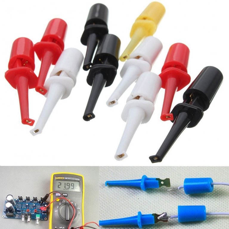
on ebay. Ten for 1,51 € including shipping are on the way to me. They are 42 mm long apparently.
- mtaylor, thibaultron and jud
-
3
-
You are right, when it comes to buying things, one needs to be sure of the terminology in order to get the right stuff. However, I often find that even salespersons are not well trained anymore in the stuff they are selling ... and the English on Chinese/Indian web-sites sometimes can be, well, challenging ...
-
Just out of curiosity: I have the predecessor to this machine, purchased in the early 1980s. At that time it had ball-bearings, which of course would not be oiled, but greased. Did they change the bearings to plain bearings, which would need to be oiled ? This would be rather surprising, as one hardly ever uses plain bearings these days.
And, yes, I use 'sewing machine' oil for my small lathes and mills, which is what the manufacturers recommended at the time.
Colour of riverboat paddle wheels?
in Painting, finishing and weathering products and techniques
Posted
Pigments and dyes in a maritime (or nearly so on inland waterways) are always interesting subjects. What was the pigment on New England buildings ? Iron oxide tends to be more yellowish/brownish, rather than bright red as a pigment. The filler in the paint may also change the hue, as would indeed the surface the paint would have been applied to. Any idea about the actual pigments and their sources in the Midwest ?