


wefalck
-
Posts
6,411 -
Joined
-
Last visited
Content Type
Profiles
Forums
Gallery
Events
Posts posted by wefalck
-
-
Are you referring to externally or internally iron-stropped blocks?
The latter have been in use at least since the 17th century for specific heavy-duty applications, such as cat-tackles, but were not used much in the rigging as such - the external strop could cause damage to sails etc.
Internally stropped blocks are much more complicated to manufacture for both, the prototype and the model. Hence, they were only used, when higher load-bearing capacity was required. They have to be attached to spars or rigging with either a hook or a ring that was forged as part of the strop. This restricts their use to certain locations.
Hooks were used e.g. for blocks attached to masts or where they were constantly under load. Otherrwise their is a risk that they became unhooked, even when a musing was used.
I gather blocks with rings only became more common when chain and wire-rope were introduced into the running rigging. They required shackles, which in turn only became more common once thread-cutting became standardised after the middle of the 19th century. With wire-rope only internally stropped blocks can be used, as it would not be possible to make safe strops from wire - the radii required are too tight around the block.
From a mechanical perspective internally stropped blocks are a much better proposition than externally iron-stropped blocks, as the strop supports the axle just outside the sheave and is not separated from it by the wooden shell. The wooden shell is only there to prevent chaving and hooking in rigging and sails.
Making internally stropped blocks in small sizes, say below 2 mm length has been bugging me for decades, as there is very little material for attaching a hook or eyebolt.
-
It's a nice site and seems to have been considerably developed since I visited in 1994. The rea around is also pretty.
-
-
In the early 20th steel was used for some parts of the running rigging that did not need to go around blocks. For those parts chain or hemp was used.
- Bob Cleek and GrandpaPhil
-
 1
1
-
 1
1
-
-
Nice ideas !
Looking at the engine, I actually wondered, whether the flywheel wouldn't actually run in a pit, making the engine foundations level with the engine-house floor. At leas this was the arrangement in most of such engines in preservation that I saw.
-
Something that one doesn't see too often, neither as model nor preserved examples. I gather they were too complicated and expensive to maintain by the average farmer. Rubber or steel tyres (as in early ones) were easier on time and budget.
In Germany, Lanz also made a tracke version of their Bulldog.
Well done - what will you do with it?
- Jack12477, Old Collingwood, Canute and 1 other
-
4
-
Somehow, I had missed this project up to now 🙁
- Mark Pearse and Jack12477
-
2
-
I probably wouldn't buy-in someone elses parts, I was thinking of kitting myself out to do 3D-printing - or at least do the designs myself. On the other hand, as for my laser-cutting, parts usually do not turn out right at first shot. As @dafi knows well, there are usually several runs necessary to get the dimensions right for printing - unlike for substractive machining, where one in most cases ends up with the correct part.
However, I love this late 19th to mid-20th century manual technology of substractive machining and those old machines. In addition, I am already spending a good deal of my wake hours in front of a computer, so manual workshop work is a pleasant diversion.
-
As has been discussed at various places around the forum, ships were built from a variety of wood species, preferably oak for structural parts (keel, stems, frames) and planking below the waterline. Other species included elm, beech, pine and fir. The latter two were mainly used for decks, spars, planking above the waterline (probably only in merchant ships), etc.
All wood on board was treated, with the exception of decks. Depending on the location and purpose pine-tar ('Stockholm tar'), coal-tar (after the 1840s) or lineseed-oil was used. Before sheathing with copper or zinc became common for ships going below a certain parallel, the underwater hulls were treated with a variety of concoctions meant to discourage fouling and attacks by Terredo navalis. In domestic waters, ships were given only a coating of heavy tar. The linesee-oil may have been mixed with different pigments (chalk, yellow and red ochre, soot) to create paints for deocarative purposes, but also for added protection against UV radiation (which as such was not really understood then).
Practices would have differed across the regions and evolved over time.
-
Well, you would also need a milling machine or a shaper with dividing head to precisely cut the square teeth - probably not worth the effort …
-
… but we are sinking slowly into technological obsolescence, considering what can be done with 3D-printing already.
- Keith Black, Ras Ambrioso, BANYAN and 1 other
-
4
-
Thanks again for your interest !
********************************
Anchor-winch 3
The winch drums were fashioned from 3 mm Ø round acrylic rod. Each side was built up from two pieces. The problem here were the square holes for the handle-bars. In principle, one could cross-drill two holes and file the square, but at 0.5 mm x 0.5 mm this would have been quite a challenge. There would be other options, such as broaching, but this requires specialised tools.
The simplest thing is to divide the drum into two parts, to slot the end of one part, cement the two parts together and one ends up with perfect square holes.
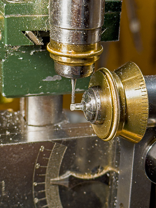
Set up for slotting the ends of the winch drums
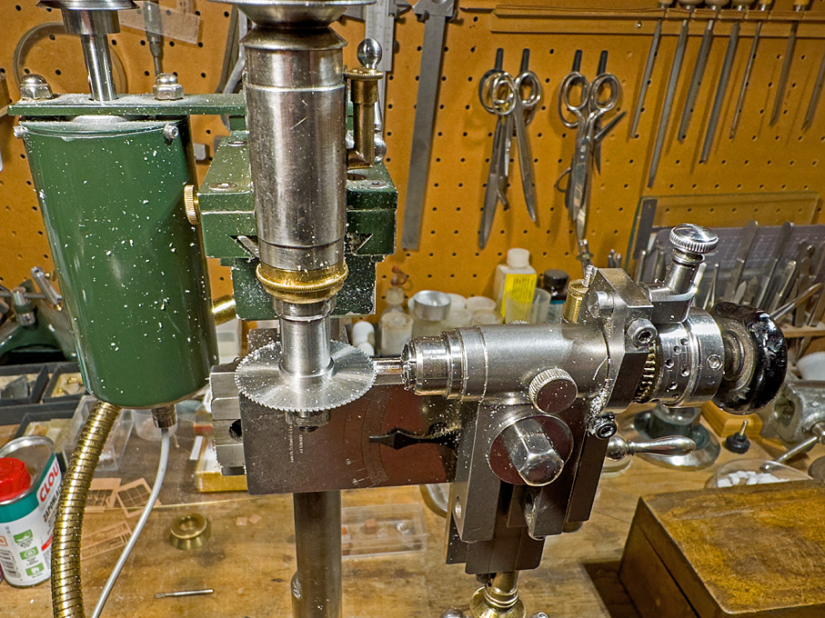
Slotting the winch drums
To this end, a piece of rod was faced on both ends, and drilled 0.5 mm for the axle. It was then transferred to the dividing head on the micro-milling machine and the ends were slotted 0.5 mm deep with a 0.5 mm circular saw. Finally, a round disc of the same diameter was cemented to the end, leaving two perfectly square cross-holes.
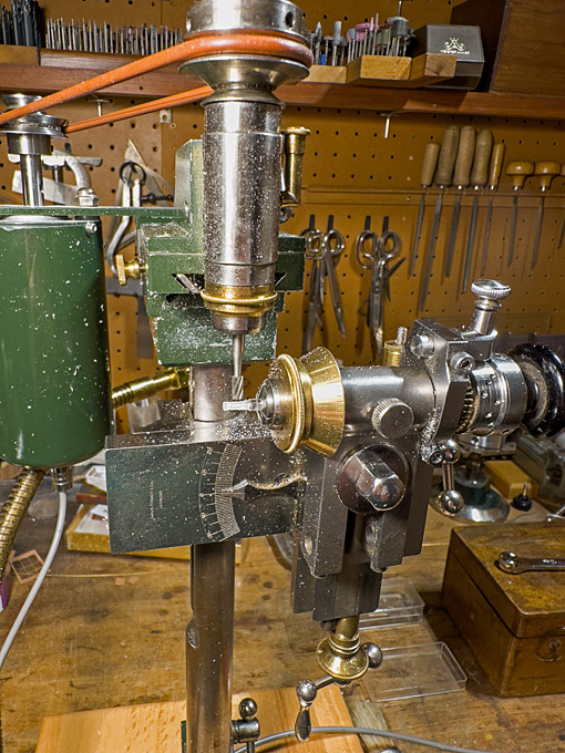
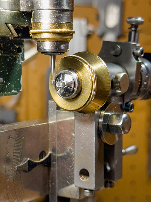
Milling the eight sides of the winch drums
In the next step, the axle of the dividing head was tilted by 1.5° for milling the eight sides of the drum that is slightly conical. The drum is bound by iron hoops at both ends. These were generated by milling the drum to 0.2 mm diameter above the target dimensions. Then, the diameter was reduced by these 0.2 mm, leaving two ‘bands’ of 0.3 mm width and 0.1 mm thickness at both ends.
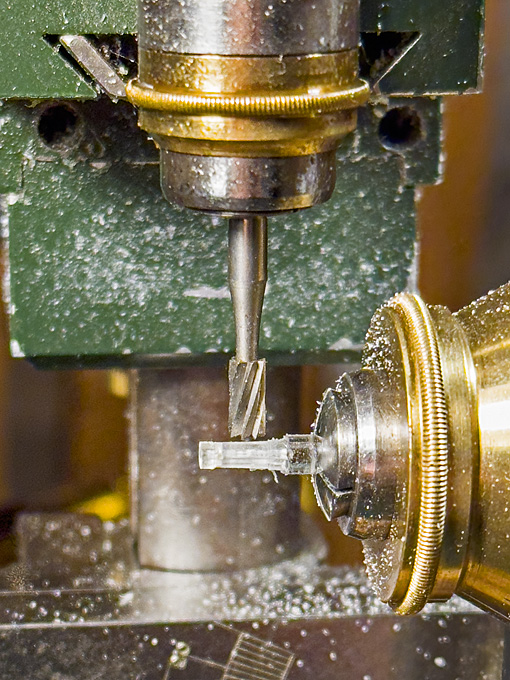
Close-up view of milling the eight sides of the winch drums
The thinner ends of the drum were faced off on the lathe to the correct length and then the drum halves parted off to the correct length.
The spill-heads were done in the same way, but are cylindrical (or eight-sided prisms), rather than conical (or eight-sided truncated pyramids). A smaller burr had to be used, as the distance between the reinforcement bands is only 1 mm. Before parting-off, the outside ends were slightly dished with a round-burr in the lathe tailstock.
Milling the spill heads
For the ratchet wheel a short length of 3 mm acrylic rod was turned down to 0.1 mm above the target diameter of 2.0 mm. The geometry for milling the ratchets was worked out on the computer. I arrived at ten ratchets 0.2 mm deep (= 32 mm on the prototype, which appears reasonable). In watchmaking there are special ratchet-wheel milling cutters that can also cut curved teeth, but I don’t have any, so I had to make do with a dovetail burr, which is good enough, as the ratchet wheel does not need to be functional. Also, two 0,2 mm thick discs as flanges were parted off.
Milling the ratchet wheel
Unfortunately, these transparent parts are difficult to photograph and, indeed difficult to see during machining. A first coat of paint will eventually show any errors …
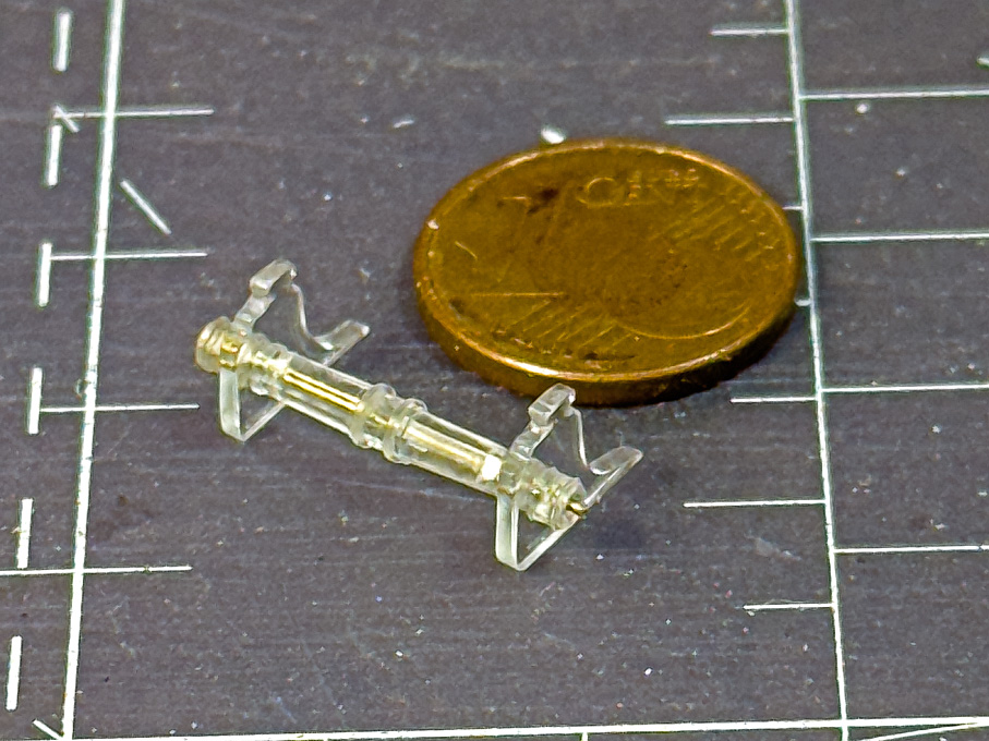
The parts of the anchor winch made so far assembled
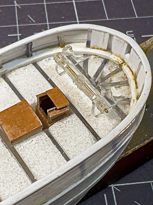
The anchor winch at its future location
To be continued …
- Rik Thistle, Paul Le Wol, Keith Black and 9 others
-
7
-
 5
5
-
If it's not too late: I would scrape off the moulding lines from the parts! Makes for a much more professional and realistic looking model.
-
... exactly - this would be a sort of 'artisanal' model finish and not a realistic representation. On real ships neither brass nails nor varnish were used at that time.
-
Such pullies and teethed (or timinng) belts are standardised items and can be obtained via ebay or Amazon. Keep in mind that there are usually two types of pullies, with flanges and without. Normally a combination of both is used (as visible on the exploded diagram) - this evens out minor misalignments between the pullies.
As you have a belt and know, where the motor and the saw-shaft are located, it should be easy to work out what pulley-diameter you need. From the exploded diagram above, it appears that there is a 1:2 reduction.
-
If it tears, it is paper. Fabric doesn't tear. I have used both for some 40+ years now. From here on I show an example for the procedure I use:
.
- Keith Black and Lecrenb
-
2
-
There is always a bit of confusion, whether silkspan refers to a fabric or silkpaper (both were used in the past to 'span' over model aircraft wings).
For the fabric you can also look for the finest screen for silk-screen printing, say on ebay.
For the paper you can look for the one that is used in book/manuscript restoring to double torn leaves. It is exremely thin and weighs only 7 g/m2. I got mine through a specialised on-line supplier.
-
This seems to be the old Revell plastic modell (built this way back around 1966 ...). The model seems to be missing the main yard, which at that time would have been involved in lifting out the launch as per the drawings from Harland. I believe HMS BEAGLE was also carrying two whaleboats in iron davits alongside her quarters. These whaleboats would have been very important as surfboats for landing on islands without harbours.
-
41 minutes ago, Keith Black said:
I detest ambiguities when trying to replicate a thing as it always takes three to four times longer to build rather than the simple monkey see, monkey do.
Whom are you telling ...
- Keith Black, Coyote_6 and Canute
-
1
-
 2
2
-
-
-
-
Anchor-winch 2
As planned, the drawings for the cheeks were printed to the correct size and stuck to a piece of 1 mm acrylic glass. A straight edge of the piece was used as reference surface.
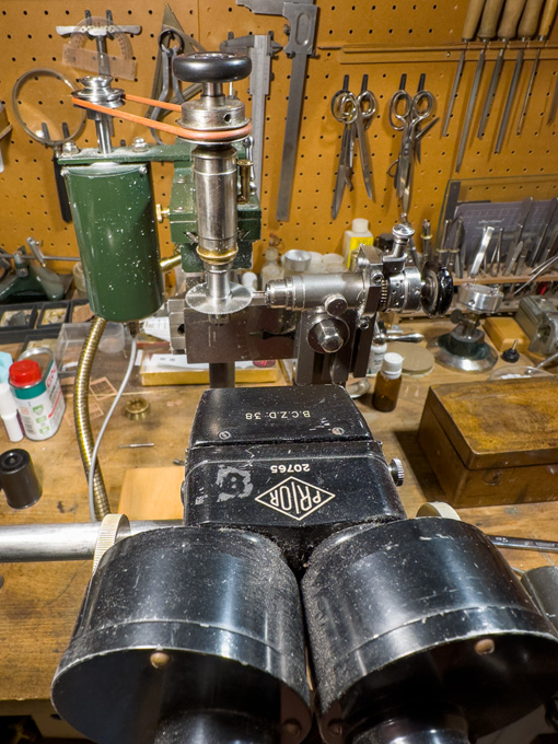
The first step was to drill the 0.5 mm hole for the axle of the winch-drum. This hole serves, together with the straight edge as reference for aligning the two cheeks so that they can be made identical. The drilling gives me the opportunity to show the watchmaker’s pillar drill (https://www.maritima-et-mechanika.org/tools/drills/drills.html) in action.

Using the micro-mill as a router, the parts were roughened out with the aid of a fine cylindrical burr. Then a process of hand-filing began, using a variety of small and fine watchmaker’s files.


The edges were slightly rounded using a three-sides scraper and a fine abrasive stick in the handheld electrical drill. Finally the parts were polished with a rotary bristle-brush.

The lower edge of the cheeks is 9 mm long. Unfortunately, the transparent parts are difficult to photograph.
To be continued …
- Keith Black, Paul Le Wol, archjofo and 11 others
-
11
-
3
Steam Schooner Wapama 1915 by Paul Le Wol - Scale 1/72 = From Plans Drawn By Don Birkholtz Sr.
in - Build logs for subjects built 1901 - Present Day
Posted
The small pad under the bit to slide under the deck is actually a clever idea 👍🏻