


wefalck
-
Posts
5,568 -
Joined
-
Last visited
Content Type
Profiles
Forums
Gallery
Events
Posts posted by wefalck
-
-
Most of my machines are (historic) watchmaking machinery: http://www.maritima-et-mechanika.org. Collecting and restoring (if needed) these machines is another hobby of mine.
wefalck
-
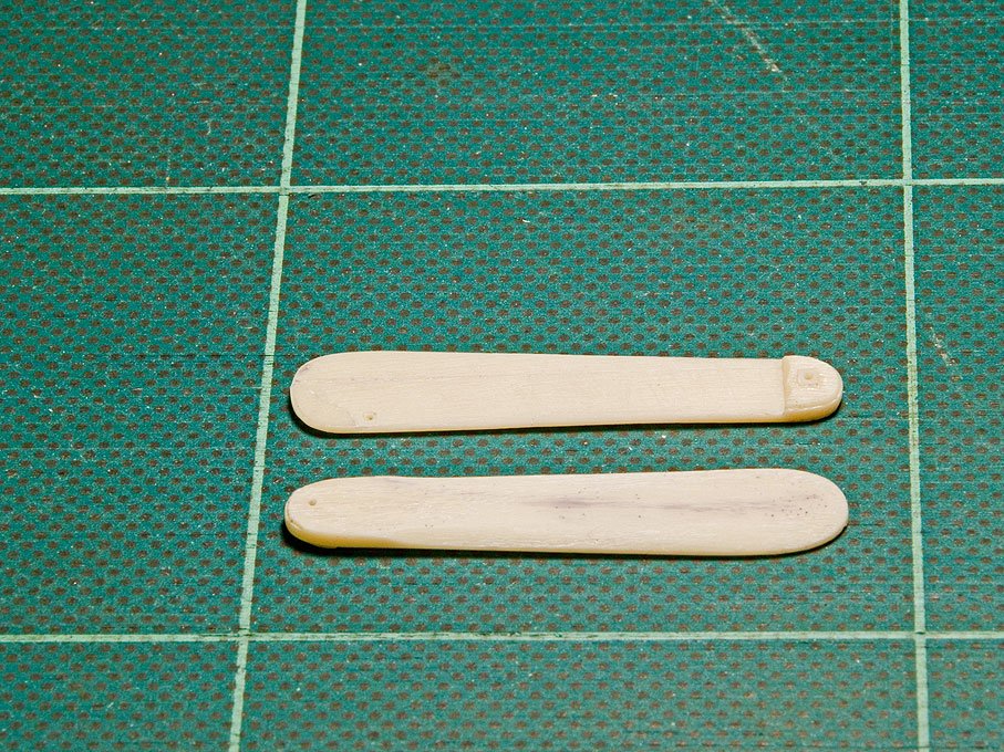
The leeboards are cast in resin, but due to the casting process in an open mold, their back is flat and without any sculpting. In reality, they are not just flat boards, but they have a cross-section almost like a propeller. In fact they are hollowed out over some part to create some hydrodynamic lift that counteracts the leeway and also pushes the leeboard against the boat. Using files and diamond rotary burrs the appropriate shape was given and also the separation of the individual boards of which the leeboards are composed were marked out.
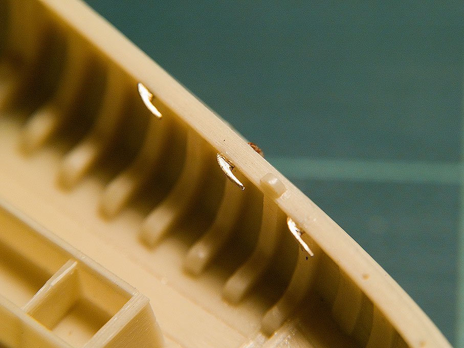
There are various belaying clamps distributed around the hull. The kit has photoetched parts for these, but somehow they appear rather flat. In addition some or all of them would have to be of the single-horned variety, rather than the more common double-horned one, as
forseen in the kit. Replacements were milled raw from a strip of brass and sliced off on the lathe. They were finished using the hand-held power-drill using small grindstones and polishers.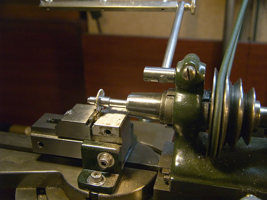
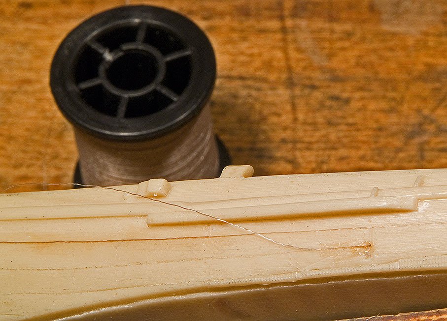
Again, the casting of the hull is nicely done, but Artitec were a bit overenthusiastic in depicting a rather worn state. If there were such big gaps in the hull, the boat would sink to the bottom of the Zuiderzee like a sieve. To counteract the rather rustic appearance, fly-tying silk was glued as 'caulking' into the gaps using varnish.
wefalck
- ESF, avsjerome2003, yvesvidal and 1 other
-
 4
4
-
-
It is always a good idea to have a foot control switch, preferably one that doesn't lock: just lift your foot and the machine stops. You have your hands free to operate the machine.
wefalck
-
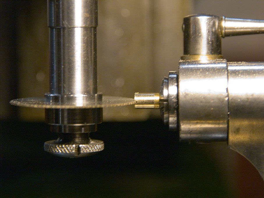
Given the problems with the spill, it was cut completely from the moulded hull in order to be rebuilt as a separate item. Square holes and recessions cannot be easily machined from the solid. Therefore the spill was built up from a number of parts that would allow machining, The
0.5 mm x 0.5 mm holes for the handle bars were cut as slots into a section of 4 mm round brass bar.
The ratchet wheel was cut on the milling machine with a dividing attachment:
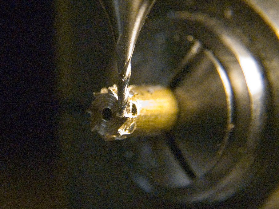
All parts had a 1 mm hole drilled through to take up a 1 mm brass rod. Brass was chosen in order to be able to soft-solder all parts together for the subsequent machining operations and to provide an axle.
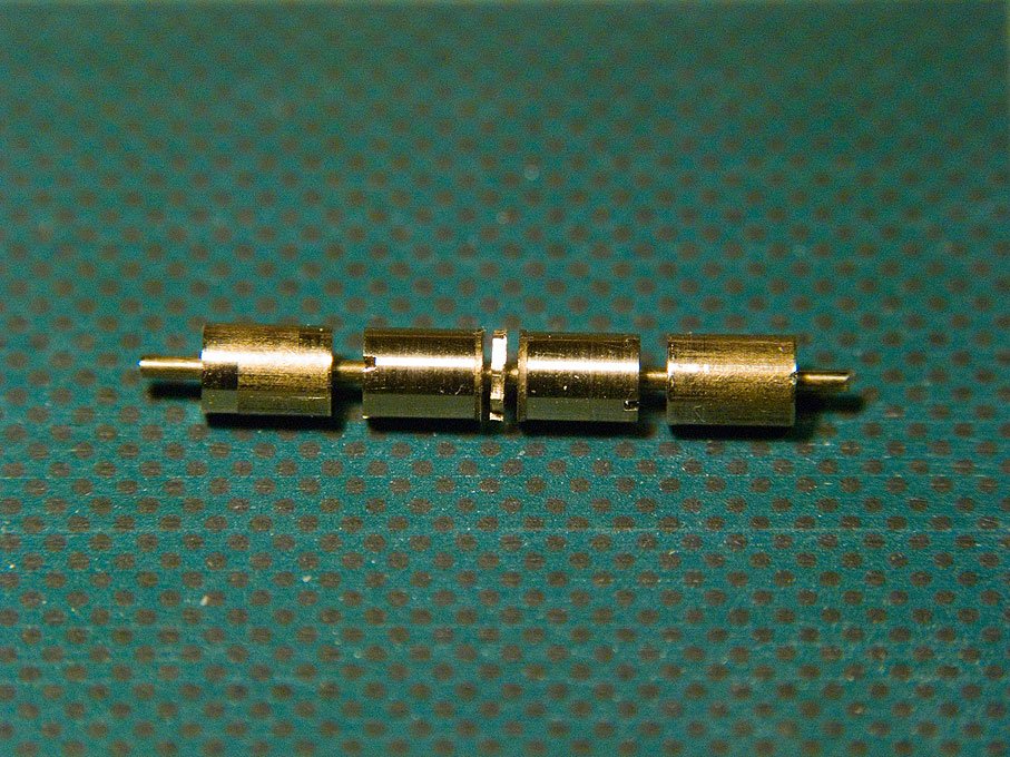
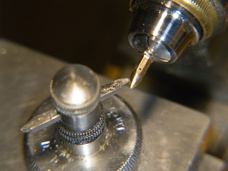
The cigar-shape of the spill was turned with the Lorch free-hand turning device:
The piece was then transfered back to the dividing attachment (http://www.wefalck.eu/mm/tools/dividingapparatus/dividingapparatus.html)
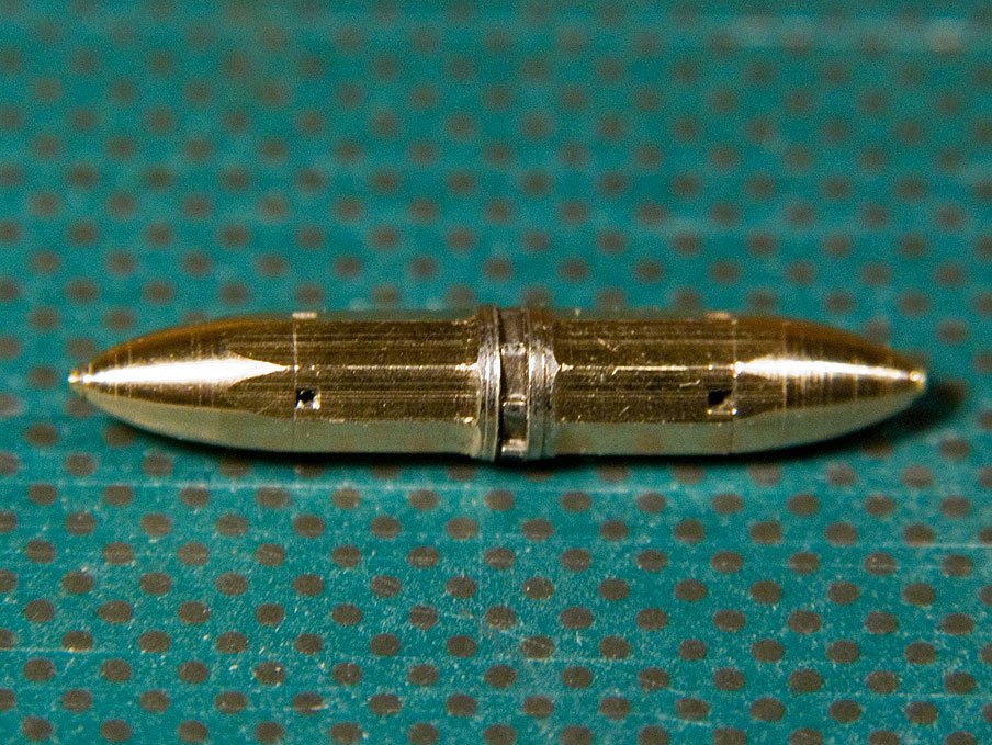
on the mill and the eight sides of the winding drum were milled on.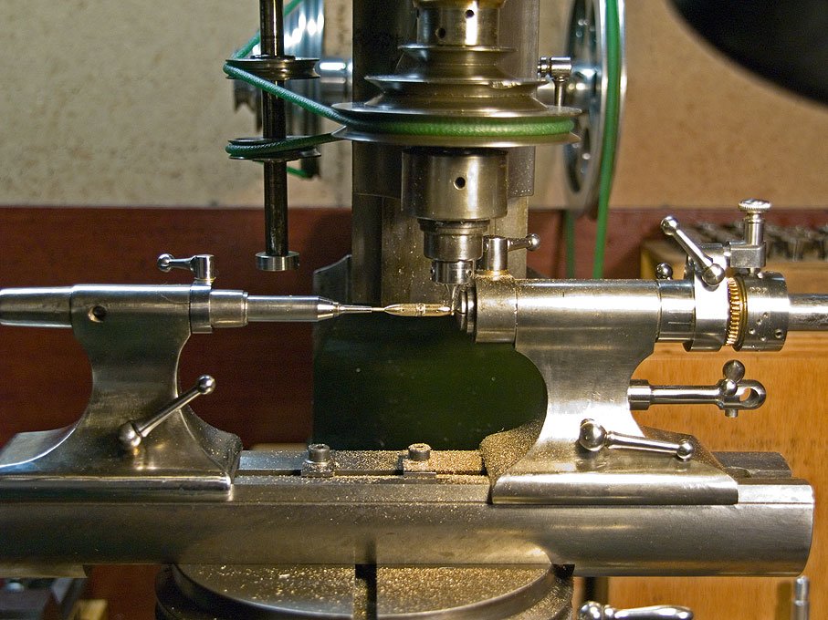
Here the completed spill stem:
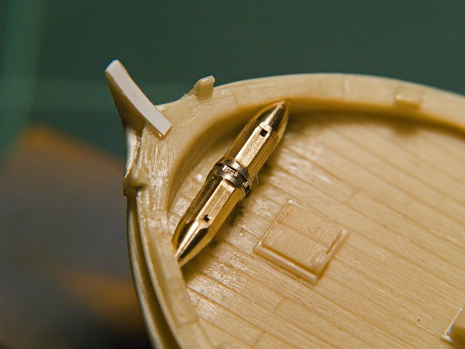
And installed in the hull:
to be continued ...
Wefalck
- druxey, yvesvidal, Salty Sea Dog and 3 others
-
6
-
I have used slices of cored soldering tin in the past. The flux can be washed out with acetone and the soft material allows it to be 'forged' into the required shape.
However, for my current project that will be mainly rigged with 0,2 mm home-made rope (in 1/90 this translates to 18 mm diameter, which is a diameter that can be handled well under all weather conditions) these thimbles would be still too big. I think, I will be filling in the eye-splices with lacquer and then drill a hole through. They will be coloured by turning a sharp pencil in them, which gives a sort of metallic finish, looking as if they have been zinc-coated.
wefalck
-
Did 3 mm double-blocks with real, grooved sheaves turned from steel, but I don't want to do this by the dozen

wefalck
-
dafi,
I recently went through a similar loop of experimenting with various fly-tying threads from UNI-thread and Sheer. When looking for more threads, I came across the company Veevus in Denmark (http://veevus.dk/en/), who seem to be quite new on the market. I ordered some spools via the electronic bay from the USA, as this was a lot cheaper than from European sources. The Veevus thread is really good and available down to 16/0. The downside is that the colour range in beiges is a bit limited, but they got one that can go as hemp or linen.
Another downside with these man-fibres is that they are rather springy compared to linen. You almost cannot leave the ends of your ropes unsecured, as they spring open as soon as you touch it. Also I found it impossible to make real(!) splices because of this. I may (re-)adopt the cheating method with a needle to showed in another thread.
And, yes, one doesn't really need the travelling bobbin, as already suggested by Bernard Frölich in his book. When working with the fly-tying threads I found that first tension builts up as the strands are twisted together. I ease this by releasing the tailstock of the rope walk. Later when I turn this end to twist the future rope together, some to the twist unwinds and the rope becomes longer again, which I compensate by moving the tailstock out again. It is important to keep a rather uniform tension. Unfortunately, the tailstock doesn't slide very well on my ropewalk due to the lever action of the rope. So I have to move it by hand.
I'll be showing soon some results from my endeavours in the building log on the Zuiderzee-botter.
wefalck
-
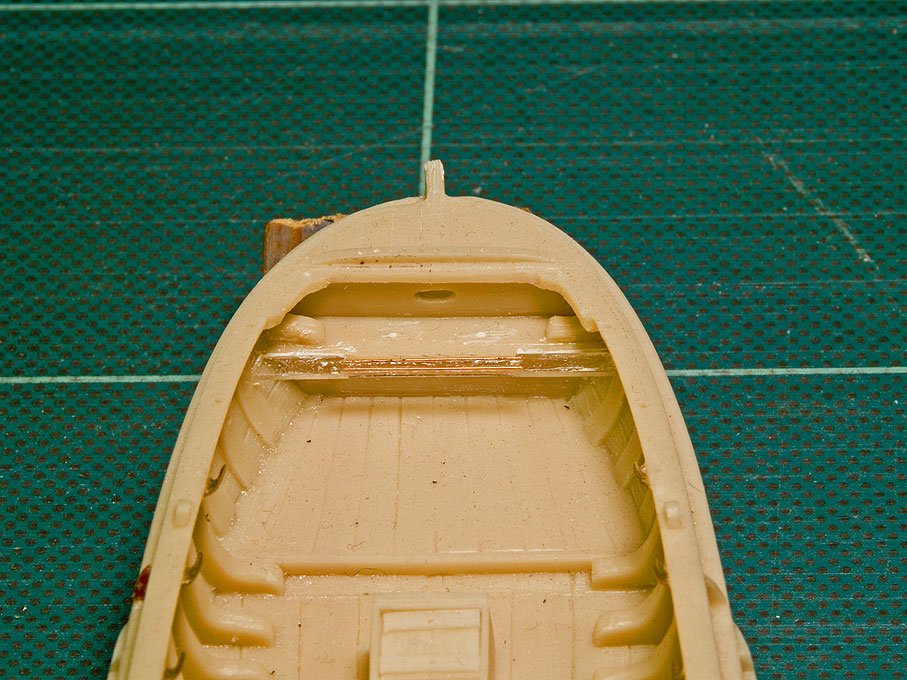
The hull casting was then inspected for any flash and it removed with a scalpell and files. Luckily, there was hardly any flash. As the next step the hull casting was compared with drawings from the literature, mainly BEYLEN (1985) and DORLEIJN (2001), as well as the above photographic images. As is discussed below, it will assumed that the model represents a botter from Marken. Botters from different regions differed in characteristic details and these should be represented as true as is reasonably possible at this small scale. When going over the casting a number of 'problems' were noted: a) the spill lacks some definition of detail, although the general shape is well represented; also a pawl bit is modelled, while normally the pawl would be pivoted on the inside band of the bow;
 the horse for the traveller of the main sheet is foreseen as an iron bar (an etched part), while the more common arrangement is a wooden horse integrated into the slightly raised stern-platform; c) the leeboards are meant to be glued onto wedge-shaped protrusions on the main bollards; on the prototype, the leeboards are suspended on a pin that ties into a band that is laid around the bollard; d) the horizontal wooden knees left and right of the stem-head are missing, but the whole stem-head has to be rebuilt anyway (it was broken off in this second-hand purchase of the kit). In addition, holes for thole-pins etc. have to be drilled through. There are other little bits and pieces that need to improved, but they will not all be listed here.
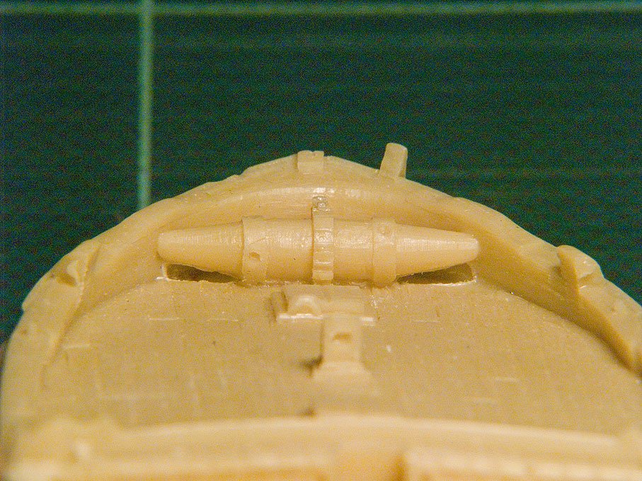
The cast-on spill
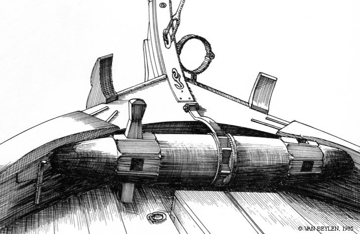
Sketch of a botter-spill in BEYLEN (1985)
In between, the hull-moulding was freed from cast-on belaying and other pins as well as the collar for the leeboards. All parts were replaced in metal for better definition. The respective holes for belaying and thole pins were opened up properly. The missing stem-head was fashioned from an off-cut piece of polyurethane resin. Bands and rubbing strakes for the forestay haliard were added from styrene sheet and copper wire.
On close inspection it was found also that the stern piece was too narrow to accomodate the pintels for the rudder. It was widened with a piece of resin stuck on. The tiller from the kit didn't look quite like what I had seen in the literature and on real boats. Consequently a new one was rough millled from a piece of plexiglas and finish filed to shape. The tiller was completed with the band from styrene that holds it together in the prototype.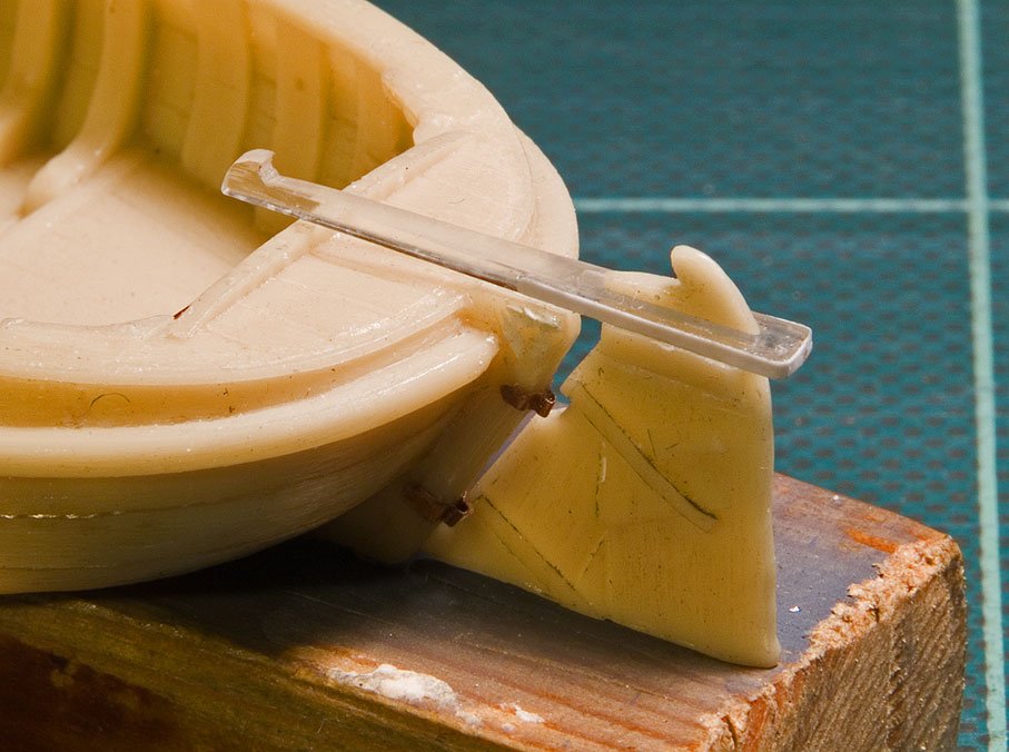
New tiller and improved rudder
The horse for the traveller was also fashioned from a piece of Plexiglas that had just the right thickness. All seams were filled with putty. From putty were also sculpted the stem knees. The horse also received rubbing strakes from thin copper wire.
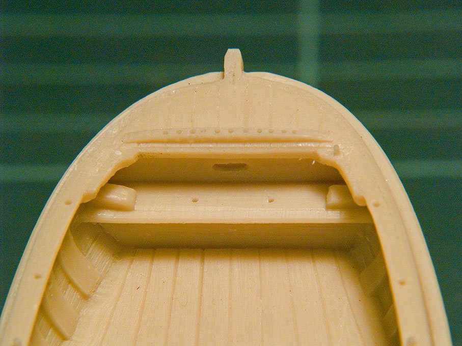
The stern of the resin botter model before the alterations.
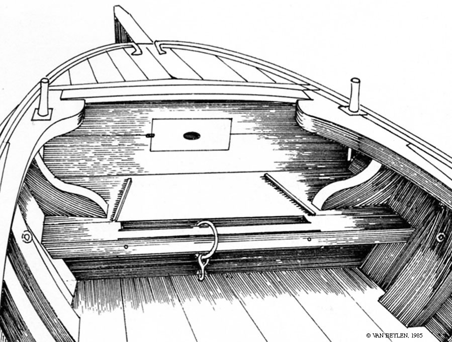
Sketch of a stern from a Marker botter by BEYLEN (1985)
Stern with improvements
To be continued ...
wefalck -
I use clear (or black for 'tarred' ropes) lacquer or varnish. Unlike in the case of PVA or CA glues, a drop of thinner softens the lacquer/varnish and thus allows you to adjust everything. The lacquer/varnish can also easily applied with a fine brush.
wefalck
-
Well-made ropes in diametres below 0.5 mm are rather scarce or unavailable at all commercially or only in a few sizes and colours. So serious miniature shipmodeller has to resort to make his own. There are various descriptions of ropewalks in the modelling literature and on the Internet to be found.
Essentially, a ropewalk consists of a headstock with a planetary drive the gives the individual strands a twist against the 'lay' of the rope, while at the other end there is a tailstock drive that twist the rope together. A travelling bobbin (the denomination varies) ensures that the strands are separated and then fed together in a controlled fashion. However, Bernard Frölich (1999) suggested that, when one keeps the strands apart at the tailstock end and then twists them together, the rope will start forming from the middle of the walk, progressing towards the headstock and tailstock. It is this principle that was used for the miniature ropewalk.
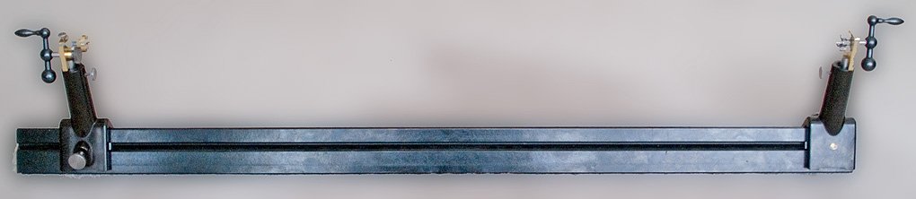 In my late fathers estate there was an optical bench with several 'steadies'. The bed is triangular in cross-section and is, as the steadies, made from solid dark-brown bakelite. It dates probably to the 1940s and was supplied by the well known German demonstration instrument company PHYWE. Not sure what my father would say about this new use, but after decades of slumbering in a dark corner of his study, it was calling for a new lease of life. It appeared to be a good base for a ropewalk and perhaps later also a serving machine, if I ever should need one.Apart from the gears that were mostly bought for the purpose, the ropewalk was constructed from pieces found in my scrap-box. The design evolved while I was assembling it, so some aspects are not as well thought-out as I would wish. For instance, for the headstock I should have purchased six pinions and installed them permanently in a hexagon. I was too mean and bought only four.
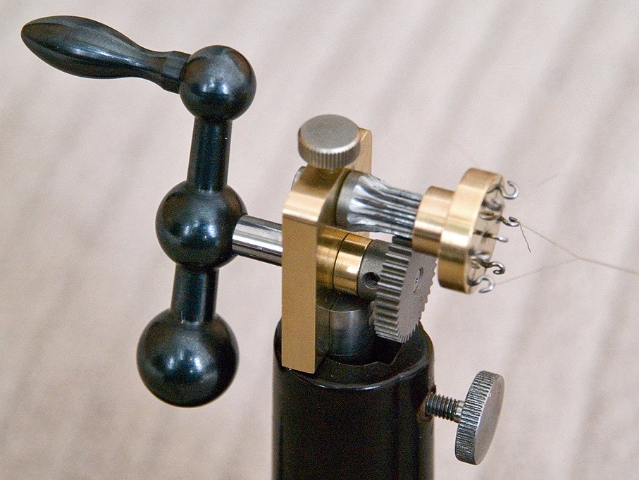
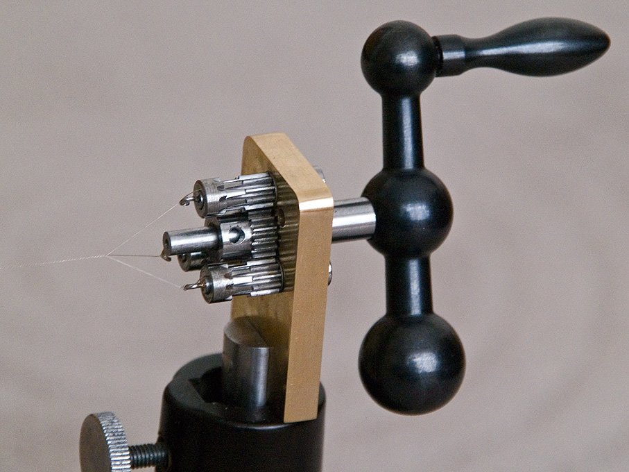 The body of head- and tailstock is a small slab of 6 mm brass. The holes for the shafts were drilled and reamed to size. On the side that would have to take up the pull of the rope a 90° cone was sunk to create effectively half a cone bearing. This a better defined position than just a cylindrical bearing. The driving shaft in the headstock was left somewhat protruding to allow fixing at a later date a clamp for holding very thin wires for twisting them together. The hooks were bent from iron wire and hard-soldered into the shafts, as were the hooks in the driving plate of the tailstock. The driving shaft of the tailstock can be blocked by a thumbscrew that acts on a small brass pad, but the very thin ropes that I am making do not exert that much torque, so this may have been not necessary.The steadies of an optical bench are not meant to travel, they are just set by a thumb-screw that screws into a triangular groove of the bed. However, the tailstock of a ropewalk has to move to allow for the shortening of the strands and the rope while being twisted together. I added round gibs made from aluminium rod. Round because I was to lazy to reproduce the odd triangular shape of the grooves. The tailstock is eased by hand to allow for the shortening because the rather long stems of the steadies lead to canting and thence to breaking of the very delicate ropes.Depending on the direction of cranking, left- and right-handed rope with three or four strands can be made.ReferenceFRÖLICH, B. (1999): L'Art du modélisme.- 304 p., Nice (Editions Ancre).wefalck
 -
I was able to rework the pulleys so it turns at about 12,000 rpm.
Are you sure the bearings are rated for such a speed ?
wefalck
-
Actually, I didn’t do so much with the resin apart from cutting off bits and pieces, but the resin is quite easy to work with, though a bit brittle.
The building begins with removing the casting pips. It appears that the model was cast upside-down, so that excess resin is found only at the bottom of the hull. This excess was cut off with an abrasive disk in the hand-held powerdrill. The bottom was then ground flat onto the waterline on a piece of wet-and-dry sanding paper. It is important to hold the hull securely during the various building steps. To this end two 2.5 mm holes were drilled into the solid part of the hull and tapped for M3 screws with which it can screwed down on a piece of wood for safe handling. The tapped holes will also used to hold down the model in its dioramic setting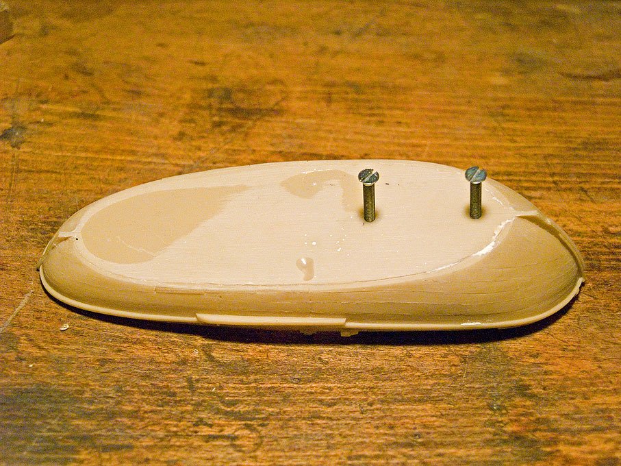
Hull with mounting screws
The hull casting was then inspected for any flash and it removed with a scalpell and files. Luckily, there was hardly any flash. As the next step the hull casting was compared with drawings from the literature, mainly BEYLEN (1985) and DORLEIJN (2001), as well as pictures taken of a Marker botter in the Zuiderzeemuseum while I was living in nearby Alkmaar from 2006 to 2009. As is discussed below, the model will represent a botter from Marken. Botters from different regions differed in some details and these should be represented as true as is reasonably possible at this small scale. When going over the casting, a number of 'problems' were noted: a) the spill lacks some definition of detail, although the general shape is well represented; also a pawl bit is modelled, while normally the pawl would be pivoted on the inside band of the bow;
the horse for the traveller of the main sheet is foreseen as an iron bar (an etched part), while the more common arrangement is a wooden horse integrated into the slightly raised stern-platform; c) the leeboards are meant to be glued onto wedge-shaped protrusions on the main bollards; on the prototype, the leeboards are suspended on a pin that ties into a band that is laid around the bollard; d) the horizontal wooden knees left and right of the stem-head are missing, but the whole stem-head has to be rebuilt anyway. In addition, holes for thole-pins etc. have to be drilled through. There are other little bits and pieces that need to improved, but they will not all be listed here.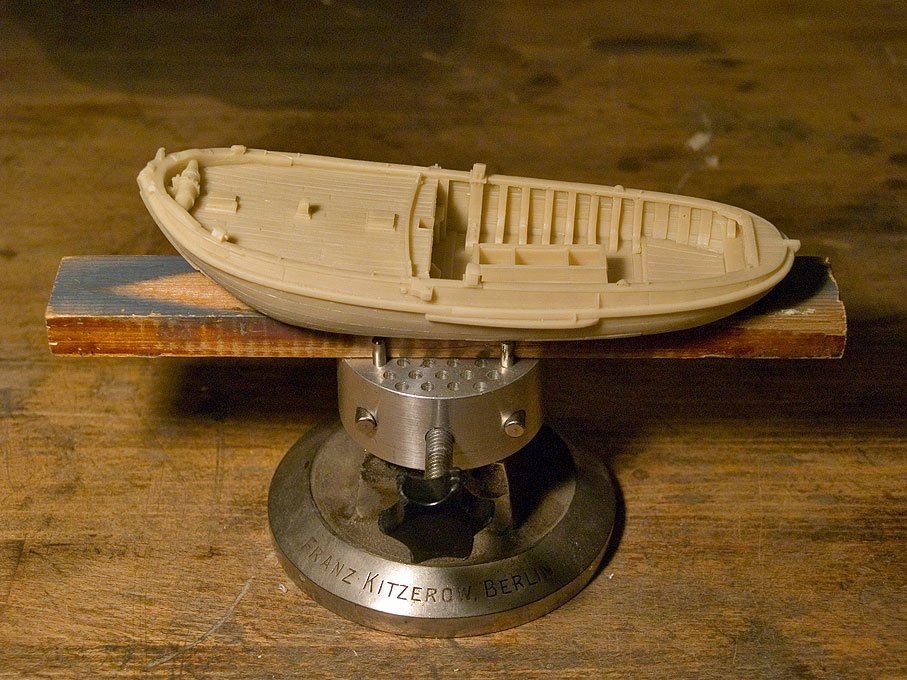
Model on working stand
to be continued ...
wefalck
-
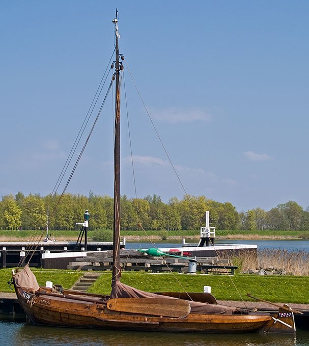
A Botter in the Zuiderzeemuseum (Enkhuizen, The Netherlands)
History and context
Looking at old maps it is amazing to see how land and water intertwined once in the northern part of the Netherlands, Noord Holland and Friesland in particular. It is even more so, when one drives through Noord Holland and reminds oneself that this once was a patchwork of islands and shallow stretches of sea. The Dutch fought - and continue to fight - the sea and at the same time a good part of the populations lived off the sea. The Zuiderzee (http://en.wikipedia.org/wiki/Zuiderzee'>http://en.wikipedia.org/wiki/Zuiderzee) once was a vast bay of the North Sea, reaching deep into the country, nearly down to Amsterdam. It served as throughfare for transport and as a rich fishing resource. However, pressure on the scarce land was high and the sea was a constant menace to the low-lying shores and islands. As part of their struggle against the sea, the Dutch dammed up the bay by a large dike, the Afsluitdijk (http://en.wikipedia.org/wiki/Afsluitdijk), completed in 1933. This put an end to much of the fisheries. The already in its southern part brackish Zuidezee finally turned into a large freshwater lake, the Ijsselmeer.
Over the course of history there have been various types of sailing fishing vessels with numerous local variants. The best-known is probably the Botter (and its larger variant Kwak). At one stage it was estimated that there were over 1000 in operation at the end of the 19th century. The places around the Zuiderzee with the most botters were Enkhuizen, Volendam/Edam, Monickendam, Marken, Bunschoten and Urk. Spakenburg was an important building place.
Man's tools to win a lifelihood constantly change and are being adapted to changing circumstances, new needs and fashions as well. Thus methods of fishing evolved in order to increase efficiency and in response to changes to the fishing grounds and other environmental circumstances that influenced the availability of the resource 'fish'. The history of the botter is not easy to trace as no artefacts have survived and artistic renderings are not so reliable bevore say the late 18th century. As with all small boats, they were built without any drawings well into the 20th century. The botter or its somewhat larger version the Kwak as we know it today developed over the past two hundred years.
Sizes vary, but a typical botter has a keel of about 34 feet long.
Sources
There are quite a number of comprehensive printed works on the botter and its history (see below). These include also drawings. Some original drawings are preserved in various museums in the Netherlands. However, like so many traditional small boats, botters were usually built without any drawings. The museums also preserve various model built from about the early 19th century onward. There are also surviving quite a number of original botters, the oldest being from the last quarter of the 19th century.
These boats survived because they have been adapted as pleasure craft. Obviously a lot of concessions had to be made in this case to accomodate the modern leisure-boaters and therefore these boats are not useful for a reconstruction. In more recent years some of these have been reconverted into a state that is more like their original workday appearance. Also, from the end of the 19th century onward some botters had been built als pleasure craft for private owners. They usually deviate somewhat from the work boats and are often fitted with a cabin, as is found e.g. on boeiers.
The Zuiderzeemuseum (http://www.zuiderzeemuseum.nl/home/?language=en) in Enkhuizen preserves a late botter in its boat-hall. The Zuiderzeemuseum also has a large collection of ship- and boatmodels, including several botters. Some of the models appear to be contemporary, while others have been built in more
recent times.
The Model
The model is based on the resin kit produced by Artitec ( http://www.artitec.nl[/url]) in 1:90 (HO) scale. This company has developed a real mastery in casting complex and large resin parts. In addition to the hull, the kit contains castings for the mast and spars, for rigging blocks and, somewhat strangely perhaps, the taken-down sails. Of course, these kits are mainly meant as accessories for model railway layouts and people not knowing a lot about these craft. The kit also contains a small fret of etched parts, mainly for the ironwork of the rigging. While the etched parts are well made as such, they are for the most part not really useful for representing the forged ironwork. For instance, masthoops are, of course, flat in the horizontal direction, while they should really be short tubes. Other parts simply lack the needed plasticity. Hence most of the etched parts will not be used. Similarly, the cast rigging blocks will be replaced by home-made ones and 'real' sails will be made. I bought the kit 'second hand' and the at some stage the characteristic high stem head was broken off and a new one will have to grafted on. Various other details will be improved for better definition of the shapes. Although the casting is well made, there are certain limitations due to the casting process. A company policy of Artitec is to limit the number of parts and to cast-on as many details as possible. Thus for instance the spill is cast onto the foredeck. There are limitations to undercuts in the silicone rubber molds, hence the barrel is not completely free. I shall have to remove the material underneath the barrel using a scalpel etc.
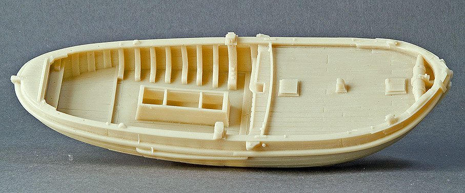
The main cast resin item, the botter’s hull
Texel Roadsted (http://www.dereedevantexel.nl) and models in various other museums around the Netherlands.


Micro Blocks
in Masting, rigging and sails
Posted
Such drills can be purchased with either 1 mm or 1.5 mm shafts from jewellers and clockmakers supply houses, or with 2.35 mm shaft from some jewellers or from modellers supply houses. The smallest drills with 2.35 mm shaft though are 0.5 mm. The others go right down to 0.1 mm. These ground drills are pricey, but their concentricity is much better than the rolled ones where the shaft diameter = drill diameter.
You may also want to look out for carbide drills with a 2.35 mm shaft on ebay, which often come cheaply from the aerospace or printed circuit board industries. They are used and replaced as part of preventive maintenance, but still good enough for our purposes. They run very well, but are rather fragile, so ou have to use them in a drill press.
wefalck