EdT
-
Posts
2,214 -
Joined
-
Last visited
Content Type
Profiles
Forums
Gallery
Events
Everything posted by EdT
-
The Frigate Naiad was published by Seawatch Books in September 2012. I am starting this topic to capture reviews, questions or comments on the book. I will also use this space to post any updates or corrections to the content. I am sure there will be some, but hopefully they will be minor. The content of the book is entirely different than the build log on this site. It is very oriented toward how-to-do-it subjects, whereas the build log is more of a day by day progress update. Please feel free to add comments here. I will be glad to address questions as well. Thanks, Ed

-
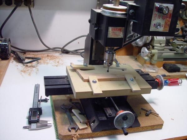
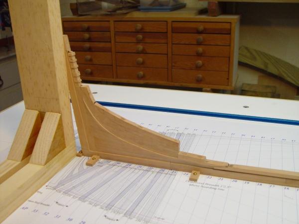
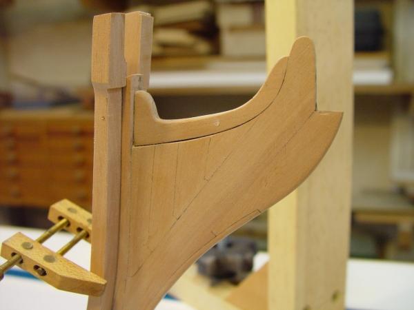
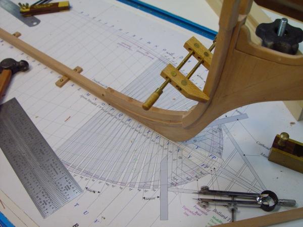
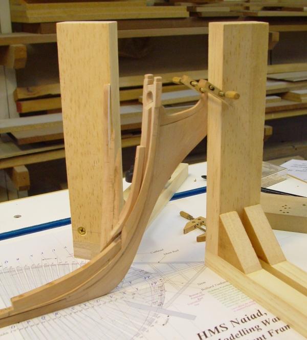
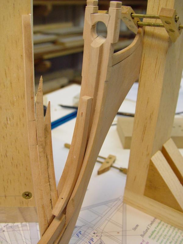
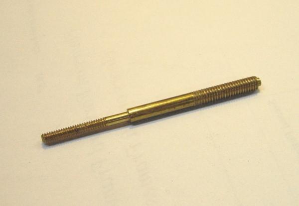
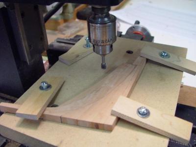
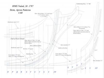
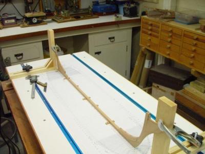
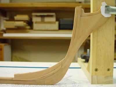
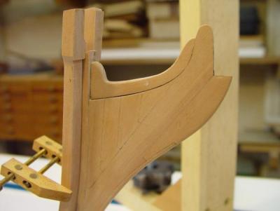
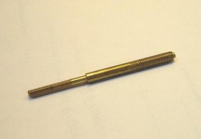
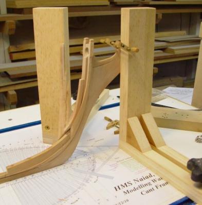
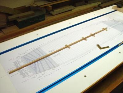
1:60 HMS Naiad 1797 Part 6 – Stern and Stem Construction Original post 10/18/10 Stern Deadwood After the timbers of the aft deadwood had been fayed and glued together, the next step was to reduce the deadwood above the bearding line to the final width of 14 ½ inches. This width is equal to the full breadth of the deadwood, 18 ½ inches, minus the 4 inches required for the two 2 inch ledges to support the cant frames. These ledges follow a curve on each side of the hull called the bearding line. On Naiad, this was a continuous curve, not stepped. The bearding line needs to be located accurately so that when the hull is faired the feet of the cant frames remain at roughly their 2 inch thickness (.033” at 1:60) and do not get faired down to less or, in the worst case, nothing. The bearding line can be copied from the original draft and put on the CAD version, but I think it is preferable to develop this line directly from the CAD body plan profiles, which are being used for all the other lofting. The bearding line passes through all the points on the hull at which the moulded breadth of the hull is equal to the deadwood thickness - 18 ½ inches. Placing a vertical line on the body plan at half this breadth from the middle line, allows heights to be taken off at each frame line to plot the bearding line in the sheer plane. This was the approach used to plot the forward and aft bearding lines on the Naiad CAD drawings. The bearding line was a bit of a mystery to me until I visualized it in this way. With a pattern for the aft bearding line in hand, the line was then marked out on the stern timber assembly, which was then set up in the milling machine as shown below. The next picture shows a closer view of this setup. I will not walk through all the steps of this milling process, but only touch on a few points. First, the work, of course, must be horizontal when milling both faces, so the assembly, which when finished will be narrower at the bottom, was not tapered until after this process was complete. Second, the machining was only carried up to within, say 1/16 inch of the bearding line, leaving the final cutting to be done with hand chisels. Finally, with the top deadwood machined to its final width, the centerline of the assembly was then determined from this and marked on all edges of the piece. After this machining, the sternpost and inner post assembly was attached and the whole fastened to the keel. In the following picture this assembly is shown shored up by one of the clamped squares discussed in Part 4. Again, at this stage I was taking few pictures. Cutting out and shaping the sternpost assembly was fairly straightforward. Heights and sizes of the mortises for the transoms were taken from the large Centerline Structures drawing. The stem, apron and forward deadwood assembly was made and attached to the keel in much the same way as its aft counterpart. Here is an image of the pattern sheet for the forward structure. There are more complicated components here, but the process is essentially the same. A separate pattern sheet was made for the knee-of- the-head parts. When all these parts were assembled and attached to the keel, the entire assembly was set up as shown below. Permanent supports for the beakhead and sternpost were added later to replace the temporary clamped squares shown in this picture holding the ends vertical. The keel was maintained on center with the small wood blocks screwed into the base with another placed just behind the sternpost. In the above closer side view, the bearding line still needs a little trimming and the stem rabbet has only been cut at the top, leaving the section down to the keel rabbet still to be done. The “rising wood,” that is, the deadwood in the center section of the hull is also visible in these pictures. This picture shows the details of the beakhead assembly with the gammoning knee in place and also the initial fitting up of the bollard timbers. The picture below shows another view of this. In the following picture the bollard timbers have been installed, the knightheads shaped and the bowsprit chock installed. Also the first forward cant frames on the port side are being positioned, but I will save the cant frame discussion for later. The bollard timbers have a complex shape. The inside faces are curved to match the curvature of the sides of the stem, which expands in breadth as it rises from the keel. The fore surface matches up to the curved rabbet of the stem, then curves aft matching the hull profile. The aft (inside) surfaces are curved to maintain the correct molded breadth at each height. The aft foot is beveled 34.5 degrees vertically with its edge fitting into a relief cut at the same angle in the apron piece above the bearding line. The outside edge, which is thankfully flat, is cut back about 1 inch over most of its length to give an air space when the first hawse timber gets butted up against it. Finally, there is a complicated bit of fancy joinery needed to get the bowsprit retaining chock to fit neatly between the upper parts, called the knightheads, which get their own little bit of shaping. The next picture is a closer view of all this. These bollard timbers turned out to be simple forerunners of what was to come with the modeling of their neighbors, the hawse timbers, which will be covered in the next part. Hold Down Bolts At this stage it was necessary to bolt the keel down securely to the building board, and it was a relief to turn to some work I could get my mind around. For the hold down bolts, special threaded studs were machined in brass as shown below. Three of these were made and were spaced out on the keel. Eventually they will be the permanent mounting bolts for the model. The idea behind this design is that the smaller diameter threaded part of this (4-40) will come up through the keel. The shoulder of the larger diameter will be stopped at the bottom of the false keel. Three small (4-40) nuts from above and three larger nuts from below will hold the keel down, initially. Eventually a small nut will be embedded just below the keelson. With the shoulder screwed up against the keel bottom, the top of the small section will be cut off flush with the top of the nut. This will prevent the keelson from being popped off by over-tightening this bolt from below later. The larger size nut under the building board or the base of the case will then hold the model down. All this work was completed by the end of February 2010. Ed Tosti ]2013 Copyright Edward J Tosti


- 511 replies
-
- 10
-

-
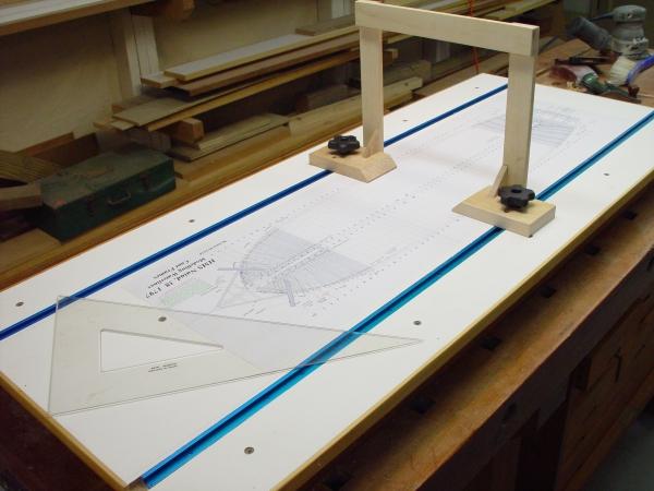
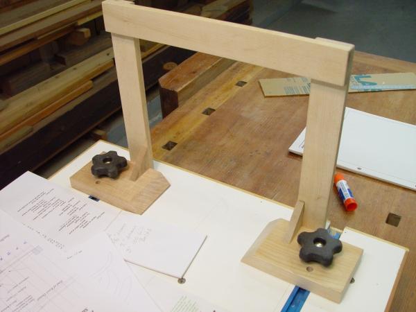
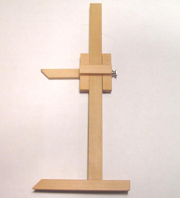
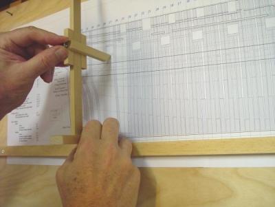
1:60 HMS Naiad 1797 Part 4 – Devices and Tools Special Devices The first items to be constructed were the building board and some measuring tools. The building board is shown below, clamped to a woodworking bench top. The board itself is a piece of ¾ inch medium density fiberboard (MDF) with some pine stripping around the sides. MDF was chosen because it is very flat and smooth. Two slots were dadoed into the top to take lengths of T-track. The board was then mounted on the 2” X ¾” pine framing salvaged from the Victory building board and screwed down along the sides and near the middle. It was checked for flatness and shimmed underneath in a few spots to make it perfectly flat and well supported by the frame. Before assembly the top and bottom were given two coats of white shellac to seal its porous surface. The top was then sanded and given two coats of flat acrylic latex paint. The centerline for the keel was scribed into the top midway between the two T-slots and a print of the full breadth plan, described in the last part, was then pasted to the top using artist’s spray adhesive. The plan was then sprayed with Krylon Protective Spray. This spray allows glue drips and blobs to be peeled off and protects the drawing from moisture. Mounting this drawing on the building board is a key enabler in the way the ship is to be built. Positions of frames and points along the frame profiles, like main half-breadth or the toptimber line, can be squared up from the board to assure correct placement. This was particularly important in setting cant frames and in marking out tenons on the transoms, which I will discuss later. I prefer this approach to the use of whole-hull jigs for the “horning” of frames, but that’s just a personal preference. Revisions are inevitable when drawings are used for the first time, and I had to make some important changes to some of the profiles. The sections of the drawing can be removed from the board pretty easily with mineral spirits and replaced with revised sheets as needed. So far, all this has worked out very well. One improvement I would make on the board based on its use so far, would be to use an oil based alkyd finish on the top – matte or semi-gloss white. This is a harder finish than the latex. Another approach would be to use melamine coated particleboard. I use this on my bench tops. It is very durable and anything can be scraped off with a razor blade. It would also eliminate the painting steps. Next time. The “gantry” device in the top picture is shown close up below. This device is similar to one I made and used on the Victory model, but with some improvements. The T- track allows easy clamping at any at any point along the ship. The edges of the two base parts align with one side of the top cross piece, so that placing the bases on a joint line, for example, aligns the top with that line. The T-track knobs allow the base to be clamped very firmly in position. Of course, in making this it was important to square it up well in all directions. The top crosspiece is scored with the centerline. A device for transferring vertical points to the inside of the hull will be added to slide on the top rail. This will be made later when needed. It will be similar to the device described below for transferring external hull heights from the drawings. In addition to this, the two sturdy squares shown in the picture below were made. This picture was taken somewhat later in construction. These squares also clamp into the T-track and are made strong enough for clamping parts or shoring up frame sides. They were carefully squared in both directions so that the face and the sides of the vertical members are accurate. A device for transferring vertical external measurements from the drawings to the model was also made and is shown below. This device, made from boxwood, is used to take vertical measurements from the bottom of keel line on the drawing and transfer them to the work. The horizontal base and the upper horizontal arm are tapered to a sharp edge. They are also held in position and made exactly parallel when the adjusting screw is tightened. This 4-40 knurled screw is threaded directly into the hard boxwood and puts pressure on a concealed brass plate when tightened. The confined brass plate prevents screw damage to the vertical wood post. Below is a picture of this device in use. The various sheer plane (elevation) views of the ship are mounted on ¼” plywood, which are hung nearby. A straight strip of pine is screwed down on the drawing so its top is just on the datum line for measurements, in this case the bottom of the keel, which corresponds to the base of the building board. Dimensions can then be transferred quickly to the work. Other devices and jigs made to support the construction will be discussed as part of the specific construction steps. Tools This is probably a good point to mention the tools for this work. As far as full sized machinery is concerned, some typical woodworking tools are being used. They include a 10” table saw with a thin kerf, carbide tipped blade, a 14” Rockwell band saw usually fitted with a ½” Woodslicer Blade, a tabletop drill press, a scroll saw, and a disk/belt sander. A reciprocating spindle sander would be nice, but the drill press fitted with a sanding drum lowered into a hole on the baseplate has been serving very well so far. The usual hand power tools, including a pad sander and a detail sander have been useful for fairing and finish sanding. Model sized machinery includes a vintage Unimat SL (lathe/ mill/ drill press/ tablesaw/ etc.), a Sherline milling machine, a Preac miniature table saw, a 4” industrial model making table saw, and a (brand new) Hogg thickness sander. This last item is essential for producing the variety of timber thicknesses called for in the scantlings. As this is being written, I am in the process of installing central dust collection. This will be a major improvement, especially for the sanders. Hand tools of many sizes and varieties are of course needed, as are the right tools for keeping them sharp. A variety of measurement tools, like dividers, squares, triangles, digital calipers, etc. are essential. A variety of special clamps have been made or acquired over the years to handle the unique demands of ship modeling. I will discuss these later when they appear in the actual work. In the next part, we will enter into the actual construction work – at last. Ed Tosti 2013 Copyright Edward J Tosti


- 511 replies
-
- 12
-
-
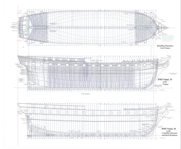
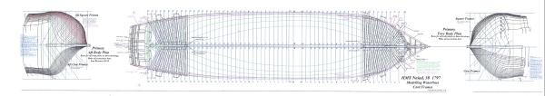
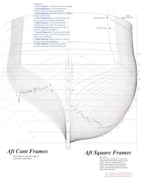
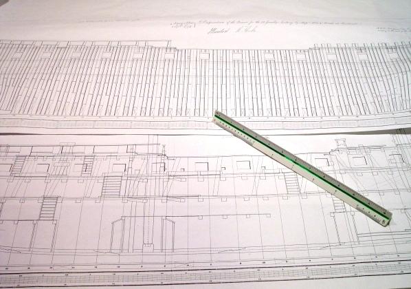
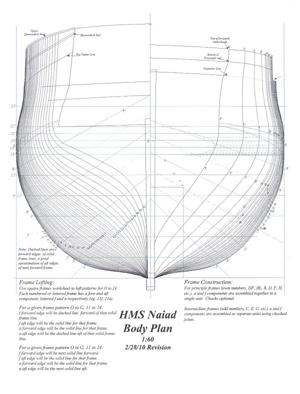
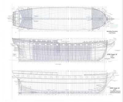
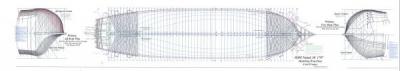
1:60 HMS Naiad 1797 Part 3 –Additional Drawings In addition to the sheer plan, three other large drawings were made to support the early stages in construction of the Naiad model and to be used later for lofting. The main portions of these drawings are shown below. The full drawings also include end views, more notes and other detail. I will describe below each of the three views shown above. Modeling Waterlines and Cant Frames The top view is labeled “Modeling Waterlines and Cant Frames.” It is, among other things, a full breadth plan. It includes, all the frame lines (including intermediates), a plan view of all the cant frames, plans of the bow and stern framing, etc. This view also includes what I have called “modeling waterlines.” These are not the original draft waterlines, which were not keel-parallel, because the ship rode deeper at the aft end. I put the actual waterlines on a separate view and used them only to check the CAD Body Plan. Then I added keel parallel waterlines based on the that Body Plan. The reason for this was that the actual waterlines are actually curved in the body plan, especially near midship where the profiles are closer together. This introduces complexity and potential error when trying to work with them to generate other profiles. Keel-parallel lines are much easier to use and this justified creating two complete sets of waterlines. So, the waterlines on this drawing are parallel to the keel at 3-foot intervals above the top of keel, plus some additional ones above the heights of breadth and some at closer intervals around the stern transoms. Other key longitudinal lines are also shown on this plan, including the height of breadth line, the sheer line (or toptimber line) and bottoms of the fore and aft top rails. All these lines were drawn from points on the CAD Body Plan. After fairness checking of all these longitudinal lines, they were used to add additional body plan lines, including: all the intermediate frame profiles, additional lines between these near the fore and aft ends of the ship where the frame bevels are pronounced, and all the fore and aft cant frame profiles. The way these additional lines were used to efficiently loft frames will be discussed later. A print of this top drawing has been pasted to the top of the building board as a construction template and for this purpose a lot of other detail and text, readable from both sides, was added to it. Frames The middle drawing in the above image is the “Frames” drawing. It is a duplicate of the original disposition of frames draft with some details added. It shows the location of these frames on the keel and how the room and space requirements were met by the spacing of these and their components fore and aft, while maintaining the correct distance between gun ports. The sidings (thicknesses) of the frame components for this drawing were taken from the Shipbuilders Repository 1788 and these were consistent with measurements on the original draft. Centerline Structures The bottom view is titled “Centerline Structures and Deck Elevations. (Actually the deck elevations, including beams and details, will be done on separate plan and sheer plane views, not on this drawing, so it will be renamed.) This view details the sternpost/deadwood/keelson structure and the forward counterparts to these. Patterns for all these components were made from the objects that make up this drawing. Frame Profile Development The following image shows the way the many additional body plan profiles were drawn and how the use of CAD simplified this process. Normally body plans are drawn in the vertical position to facilitate transfer of points from the sheer draft to create longitudinal lines in the body plan view. Then waterline breadths, for instance, need to be picked off and transferred to the body plan to create more profiles. In CAD the body plans can be easily split and rotated. Also, once a waterline is drawn, it can be copied, pasted and flipped vertically to show an exact duplicate on the other side of the ship. In the above view the fore body plan is shown at the fore end of the ship and has been rotated to the horizontal. The aft body plan has been similarly rotated placed aft. In these positions points from the longitudinal lines can be directly placed on the body plan by the use of a long movable horizontal line. This eliminates picking off points, so is much faster and more accurate. By this means, profiles for the intermediate frames (on the upper half of these views) and the all the cant frames (on the bottom halves) were drawn. The final body plans could then be copied, pasted, rotated and used as desired. Following is a vertical image the final aft body plan. On this drawing the cant frames are shown on the left and all of the square frame lines to the right. Dotted lines between frames are intermediate lines, which will be used later in the frame lofting process to show frame bevels. I will describe this later when we discuss how the frames were made. Also, note that the cant frames are shown from directly aft. These are not true views. These views will have to be rotated to obtain a true view. This will be done in the lofting process for cant frames, which will also be covered as part of the discussion about making those frames. The other information on this drawing includes, the waterlines (in green) including additional ones at 18 feet and above, straight versions of some of the actual waterlines (in purple), the diagonals with their description in a note (in blue), stern post/keel shape, etc. If you have persevered to this point with all this drafting discussion, relief is at hand. I will move on to the construction in the next part. Additional drafting and lofting will be covered with specific construction topics. So, off to the shipyard…. Ed Tosti 2013 Copyright Edward J Tosti

-
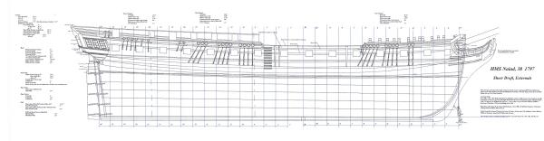
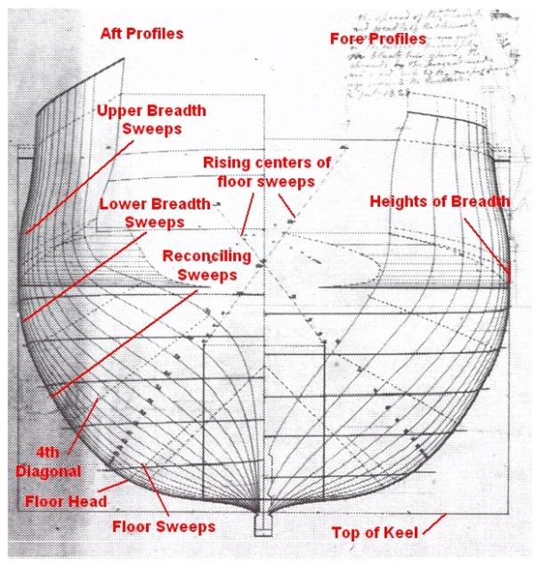
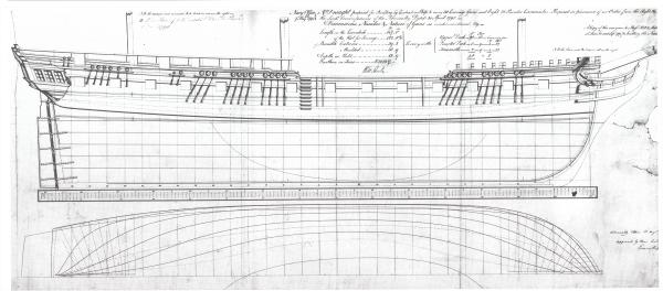
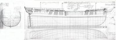
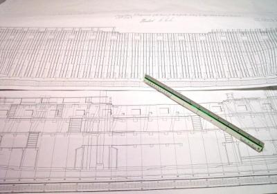
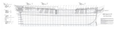
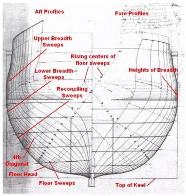
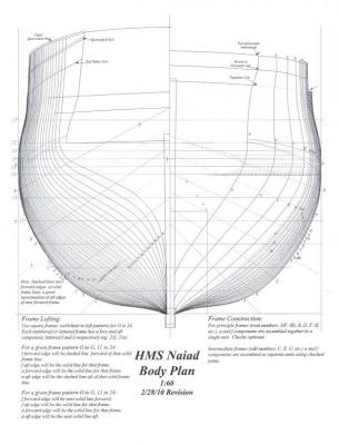
1:60 HMS Naiad 1797 Part 2 –Basic Drafts I hope the next two parts, which are text heavy, will not be a turn-off to those not too interested in drafting. For me drawing is intertwined with the actual modeling, and so, I wanted to give it proportionate coverage. I will also add that the drafting process helped me tremendously in understanding the construction of the ship and in giving insights valuable later in construction. For those less interested in this, it may be heavy going, but fear not, by part 4 we will be into construction – and more pictures. In this first part I will cover the steps I went through to reproduce a 2D CAD version of the original Admiralty lines draft. This is the basic drawing and the starting point for everything else. Many additional drawings have been made or will be made and will be discussed later. For those unfamiliar with the terminology, the lines drawing includes a sheer plan, which is actually not a plan by modern definition, but a side elevation of the external features of the ship and several important longitudinal lines. I will usually refer to this direction of view as the “sheer plane.” The lines draft also includes a plan view (from above) of key longitudinal lines called the half-breadth plan, which in addition, shows locations of cant frames and hawse timbers. The body plan to the left is a split elevation view, the left side a view from aft and the right side from forward. The body plan shows the shapes of the hull at each joint line (sometimes called frame lines or stations), plus a number of important reference lines. Joint lines represent vertical planes, perpendicular to the keel at the joint line of the two frames that are fastened together to make up a main frame bend. I will use the term “joint lines” to refer to the main frame joint lines shown on the original draft, and the term “frame lines” to refer to all the frame lines, including the ones in between not shown on the original drawings. A scan of the original Naiad lines draft is shown below. After completion of the lines draft, other basic drawings were made by the surveyors. The profile drawing is a view of the sheer plane (side elevation) along the middle line of the ship, showing internal structure, the keel assembly and internal deck details. The framing drawing, or “disposition of frames” is a view of the sheer plane showing all the frames and each of their timber parts, called floors, futtocks and toptimbers. Below are the actual profile and framing drafts on my real (non-computerized) drafting board. These original drafts could be used for model making, but there are some issues to be considered – one specific to my model and at least a few that are more general. The scale of these drafts is 1:48. My model is 1:60 - an obvious issue. Another issue is that if the basic drawings are used, then lofting will be done manually, or at least semi-manually. With the original drawings it is less easy to make the drawing fit the construction process needs. I will discuss this more later. The last relates to potential for distortion or other inaccuracies in these very old drawings, which I will discuss below. I made the Naiad drawings using 2D CAD, with an old Windows application, Visio Tech 4.1, which I have used for many years. It is dated, lacks some features, but was quite adequate. There are many advantages to CAD: It can be very fast for some tasks. It produces very high quality drawings with lines down to 1 pixel wide. It is easy to move views and objects around for different purposes. It excels at quickly expanding canted surfaces to their true view for lofting. It is easy to print off copies and make revisions. Multiple copies of patterns are easily printed to paste to wood blanks, use as assembly patterns, or to make alignment gauges. It’s easy to add a lot of legible text to drawings and color can be used and printed. All the work is done in actual measurements so conversion is minimized and prints for different scales can be made quite easily. I am not going to go through this drafting, step by step, but only highlight some areas. I may go deeper on some of the lofting, but will save that until discussing its use in actual construction. The Lines Draft The first steps in making the CAD lines draft are quite easy. The top of keel is drawn first and it’s pretty hard to miss with a straight horizontal line. Perpendicular vertical lines at each end of the gun deck, known as the aft perpendicular (AP) and fore perpendicular (FP), are easy because the length of the deck is stated in feet and inches on the draft. The next step, location of the midship perpendicular or dead flat (DF) requires the first real measurement to be taken from the draft. This first measurement introduces the issue of drawing error and measurement error. Error in these old drafts can result from measurement error when they were made, distortion of the originals over time, line blurring, reprographic error and the practice of using wider pen width for some lines. To determine the accuracy of the lines draft – the most important drawing - I first checked the accuracy of the scale at the bottom of the drawing at the right, center and left of the sheet, then checked horizontal measurements on the drawing against dimensions stated on the drawing. This was done for example, by measuring a length on the bottom scale in mm, converting it, then comparing. The results indicated an error range of from .16 % to .4% depending on where dimensions were taken. For all but the largest dimensions I concluded this level of error was inconsequential for modeling purposes. Accuracy of the draft vertically could not be easily checked, so I decided to ignore it given the small horizontal error. So, the dead flat was able to be located reasonably well. The next critical dimension to be measured was room and space. Room and space is the distance between each frame line (including intermediate frames) or one-half the distance between (most of) the joint lines – the lines at the center of the main frame bends. Used in conjunction with the specified fore and aft sidings of the timbers it assured a defined ventilation space between frames – critical in these rot-prone ships – and critical in the model for proper location of frames and frame lines. I measured this a number of ways before fixing the value at 29 inches. Once all these basic construction lines were drawn, I essentially followed the process described in The Shipbuilders Repository 1788 for constructing the sheer draft. Although the language is ancient and sometimes difficult, this book lays down how designers actually constructed these drafts, in detail – the section on the sheer plan alone is 26 pages. The book was an instructional text for aspiring surveyors and shipwrights – and unknowingly, for at least one 21st century model draftsman/builder. Below is a very reduced image of the resulting Naiad CAD Sheer Draft. The Body Plan The original body plan shows the shape of the hull at each joint line, and is therefore a critical design drawing. All the lines are “moulded” breadths, that is, they are to the outside of the frames, not the outside of the planking. To produce an accurate model, the body plan needs to be reproduced as accurately as possible. Historically, after the body plan was drafted, it was used to produce the waterlines, ribband lines and some other key longitudinal curves that make up the half breadth plan. These curves were then checked for fairness and, if necessary, the body plan was adjusted to yield fair longitudinal curves. Even though the original draft body plan was checked and adjusted by the designer, this process was followed for the CAD plans. Original body plans were drafted using circular arc segments, called sweeps. By varying the diameter and center of these arcs along the length of the ship, the final hull profile was developed. The resulting underwater shape determined key qualities of the ship – sailing characteristics, hold capacity, stability, etc. During the 18th Century, the underwater bodies of this type of ship were drawn with three sweeps, which are pointed out below on the original Naiad body plan, along with some other information, in red For those not familiar with this construction, I will try to describe it. First, British ships had a straight vertical section at the extreme breadth of the hull which ran between two dotted lines called the “heights of breadth. This straight section was larger at midship and decreased toward the ends. It is described by dotted curved lines in the sheer plan and on the body plan. The lower breadth sweep for each joint line started at the bottom of this section and swung down, with its center at points on a horizontal line through the bottom height of breadth. This formed the hull shape just below the height of breadth. The designer set the diameters of these sweeps. Starting at a horizontal line a short distance above the top of keel, the floor sweeps were swung upward with their centers on a rising line shown in the above drawing. This rising line was based on curves drawn by the designer on the sheer plan. On the sheer plan the vertical rising line is the wide u-shaped curve in the center of the lower hull. Its horizontal counterpart is an inverted u at the bottom of the half breadth plan. These curves and the diameters of the floor sweeps were also designer decisions. A third sweep, called the reconciling sweep connected these two tangentially. Its curvature was set by the designer, often by setting a point on the 4th diagonal, through which the arc would be drawn. Finally, a concave curve from the lower end of the floor sweep to the rabbet of the keel would complete the underwater body. Historically, French frigates generally seem to have had smaller diameter breadth and floor sweeps and large diameter, long, reconciling sweeps. This made for a sleeker hull, but a smaller hold. British ships generally had larger diameter breadth and floor sweeps, yielding more hull volume. The upper breadth sweeps were generally all the same diameter and were drawn upwards from the top of the height of breadth. A reverse curve would take this to the top of the side. If I were recreating this drawing manually, I would do so with these circular arcs. The Naiad draft has virtually all the information on it to do this. However, Visio does not have good tools for creating tangential reconciling sweeps, so the arcs, plus spline curve functions, were used to make the CAD Body plan. This was then carefully checked against the original by printing the CAD plan at 1:48 on transparency film, laying it over the draft, marking any deviations, then fixing the body plan and repeating this process until both were virtually identical. Also, points along diagonals and waterlines were measured from the original and checked on the CAD version. A version of the CAD Naiad body plan is shown below. At this stage, CAD versions of two parts of the lines draft were complete and ready to be used for the next stages of the drafting process, which will be described in the next part. Ed Tosti 2013 Copyright Edward J Tosti
- 511 replies
-
- 13
-
-
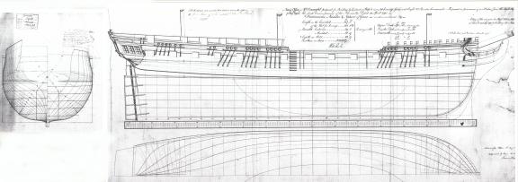
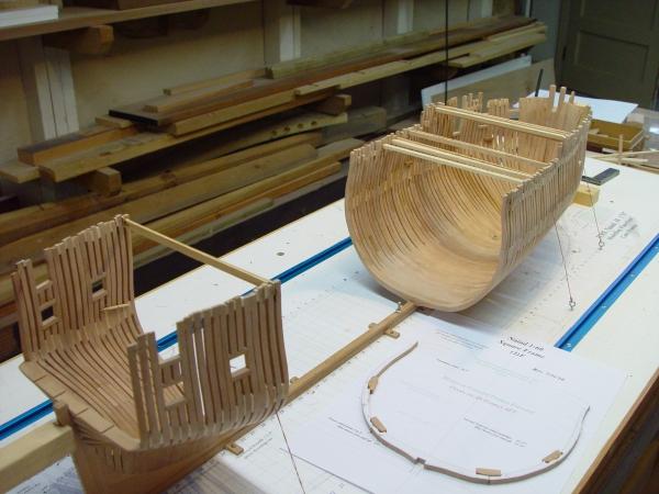
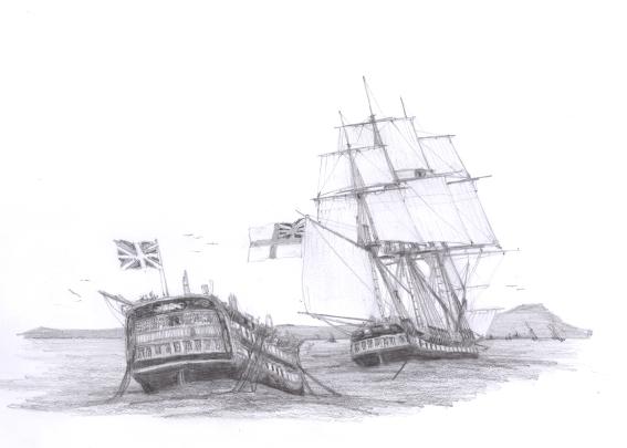
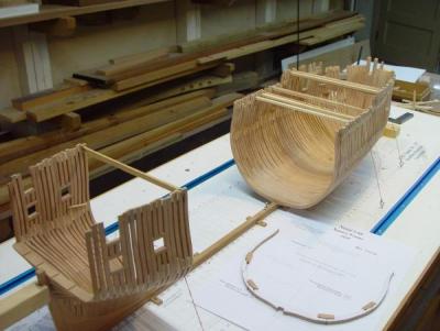
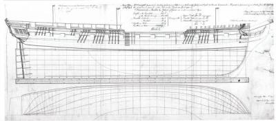
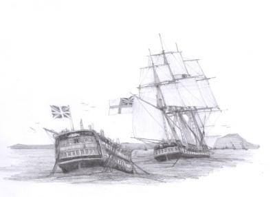
1:60 HMS Naiad 1797 Part 1 – Introduction After completion of the 1:96 Victory model (see MSW Scratch Build Logs), which is now safely confined to its case, I wanted to begin a new project, and so, after some research and consideration I have begun work on HMS Naiad, a 38 gun Frigate of the Royal Navy, launched in 1797. Naiad is a much smaller ship than the 100 gun Victory and more recent by over 30 years, but that was a mere split second of time considering the glacial pace of change in the British Admiralty. So, generally speaking, Naiad and Victory were contemporaries. Naiad was one of many ships built in response to the crisis following the French Revolution. Below is a picture showing the state of the modeling effort so far. This picture was taken in mid-August, 2010. The forward framing has been erected back past mid-ship and the square framing forward of the aft cant frames is about to begin. This project has been underway for about eleven months now. To begin these notes I would like to go back to October 2009, when the visible progress consisted of three Admiralty drawings and a stack of reference books on my desk, and start the discussion there, at the time Naiad was considered as the subject. Startup There were several goals I had in mind for the new project. Because Victory models are so common, I wanted to build something much less so this time. I wanted something less complicated because I wanted to model the full original framing and wasn’t sure how long that would take, especially for a very large ship, and for a first try at this. At the same time I wanted a scale that would produce a final model of manageable size, one that could sit nicely on a table. I have an ongoing interest in the history of the French Revolutionary and Napoleonic periods and wanted to stay in that timeframe. Finally, I wanted to engage in the full shipbuilding process, starting with basic drafting, through lofting, and finally, construction. This approach gave me considerable latitude in selection of a subject, since availability of model drawings was not an issue. To me that was a plus. I had thought about Naiad several years ago and actually ordered the three available drafts from the National Maritime Museum at that time. Also, a few years ago I started on some drafts for a possible model of Diana, based on David White’s book, The Frigate Diana, in the Anatomy of a Ship series. After reading and digesting Robert Gardiner’s great books on British frigates (The First Frigates, The Heavy Frigate, Frigates of the Napoleonic Wars) and after poring through David Lyon’s, The Sailing Navy List to see what other drawings were available, I settled on Naiad, a typical British Fifth Rate, a 38 gun, 18 pounder frigate of the desired period. Naiad History Naiad was part of a major build up of British Naval strength in response to wars that began in the aftermath of the French Revolution, wars that became more threatening to British interests as French victories on the continent mounted, even before Napoleon. Design for the Naiad was proposed by Sir William Rule, surveyor, in 1795. She was built by Hill and Mellish, at Limehouse, and launched in 1797. Several ships were designed at this time in response to requests for larger frigates and also to address naval officers’ demands for ships with improved sailing qualities – specifically ships “more like the French,” which many believed to be superior. Naval officers were popular politically, and indeed, a number were members of Parliament, so the surveyors, grudgingly, I suspect, did their best – to a point. Some ships were directly copied from French captures, and some like Naiad, made some compromises, but still retained qualities important to Britain’s particular strategic needs – large holds to support provisioning for long cruises, seaworthiness and structural strength. Naiad would outlive the short infatuation with French designs. Below is a scan of the Admiralty Draft of the sheer plan, and half breadth plan for Naiad. This drawing is dated September 1795 and signed by Sir William Rule. Naiad was a “one-off” design, the only ship of her class. However, she was a close descendent, in fact what appears to be only a stretched version, of Rule’s earlier 36 gun Amazon Class (Amazon 1795, Emerald 1795). And she had descendents in Rule’s 1796 Class of 38’s, also under the Amazon name and 3 feet longer (Amazon 1799, Hussar 1799). Naiad was fast in a strong wind, less so in calmer winds, given to pitching, but could handle six months provisions easily. All these ships had their idiosyncrasies, and all the early 38’s had some sailing problems, generally related to too many guns on too short a gun deck. Nonetheless, Naiad was a serviceable ship and had a long and successful career. Naiad is best known for her role at Trafalgar in 1805. She was one of four frigates attached to Nelson’s fleet (Naiad, Euryalus, Phoebe, Sirius). In the hours before the battle these ships observed and shadowed the French and Spanish as they emerged from Cadiz. The chain of frigates signaled the enemy movement to Nelson, in the flagship HMS Victory with the main fleet. The frigates did not join the battle line, but in the stormy aftermath of the battle, Naiad took HMS Belleisle, a battered, dismasted 74, into tow and brought her safely into Gibraltar three days later. Naiad with Belleisle entering Gibraltar During the wars with France, Naiad captured or helped capture several prizes. She was eventually sold out of the Navy and ended her days in other service 1898. Except for Victory, she survived longer than any other Trafalgar veteran. This was a very long lifetime for one of these ships. Naiad Specifications Naiad’s principle specifications were as follows: Length of the Gun Deck, 147’ 0” Length of the keel for tonnage, 122’ 8” Extreme Breadth, 39’ 5” Moulded Breadth, 38’ 9” Depth in the hold, 13’9” Tonnage, 1014 Guns on the Upper Deck, 28 18 pounders Guns on the Quarterdeck, 8 9 pounders and 4 32 pounder carronades Guns on the forecastle, 4 9 pounders and 4 32 pounder carronades The Model Project The model will be a 1:60 fully framed replication of the original ship. The frames will be chocked. Futtocks will decrease in siding and molded breadth as they progress upwards, based on contemporary scantling information. Spacing between futtocks and spacing of frames will follow the Admiralty Disposition of Frames Draft. The extent of planking or additional detailing has not yet been decided. It is unlikely that the model will be rigged. All the framing will be Swiss Pear with some minor use of heartwood cherry where some contrast is desired, for example in the fillings between floors and lower futtocks. European boxwood will be used for topside planking and at least some of the detailing. Castello may be used for some interior framing. The model is being built in the upright position, without full body framing jigs. “Horning” of the frames is being done with squares and profile gauges, squared up from a fully detailed plan drawing, laminated on top of the building board. . This level of modeling will be a new challenge for me, and I hope not too many compromises will be made. Progress The project began in October 2009, while the Victory model was in its last throes of construction. The first task involved preparation of 2D CAD versions of the Admiralty Drafts. Once the CAD Drafts of the Sheer Plan, Body Plan and Half Breadth Plans were completed and thoroughly checked against the originals, substantial information, additional lines, scantling information, and new views were added. Much of this information would be needed to complete the CAD lofting of all frames and timbers. Construction started in January 2010, with fabrication of the building board, some measuring tools, board fixtures and a clamping jig for frame assembly. The first parts of the keel were assembled and laid on the board on January 19. Here is a picture taken right after that important event. With all this background out of the way, the remainder of this series will focus on the actual model work. In it I would like to focus not only on the visual construction progress, but also on two aspects that give me a lot of satisfaction from this craft, and will, I hope be interesting to others. The first is the relationship between drafting and construction, specifically, how drawings were developed and applied to support the specific modeling processes. Second are processes themselves. I like to explore processes and get to one that works for me, and that might work for others. I do not advocate any of these methods or criticize any other. I will merely describe what I did, being candid about pluses and minuses. In the next part I will describe the CAD drafting of the basic views of the lines draft. One down, 175 to go! Ed Tosti 2010 Copyright Edward J. Tosti
- 511 replies
-
- 11
-
-
Welcome back. We have a lot of work to do. Fortunately I have all the Naiad posts saved as Word files and all the associated images, so I will be putting up the entire 176 parts as soon as I can. The model is approaching completion, so I do not expect more perhaps 10-12 new posts, but there has been enough interest in the old posts to make the effort worthwhile. We will all need to be showing a lot of patience for awhile. I will also opening a topic in the book section for "The Naiad Frigate - Volume I. There are some content updates I want to share there. I will also be reposting the 1:96 Victory Build log, but that will be taking a back seat to Naiad for awahile. Cheers, Ed
- 511 replies
-
- 22
-