HOLIDAY DONATION DRIVE - SUPPORT MSW - DO YOUR PART TO KEEP THIS GREAT FORUM GOING! (78 donations so far out of 49,000 members - C'mon guys!)
×


EdT
-
Posts
2,214 -
Joined
-
Last visited
Content Type
Profiles
Forums
Gallery
Events
Everything posted by EdT
-
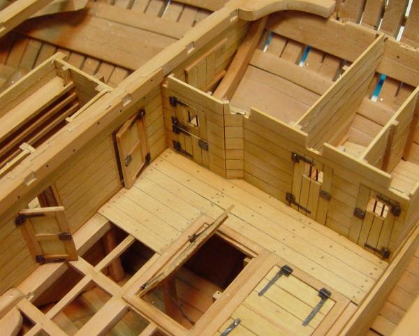
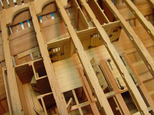
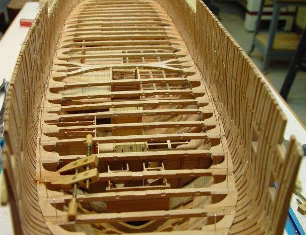
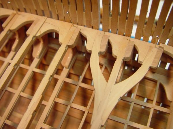
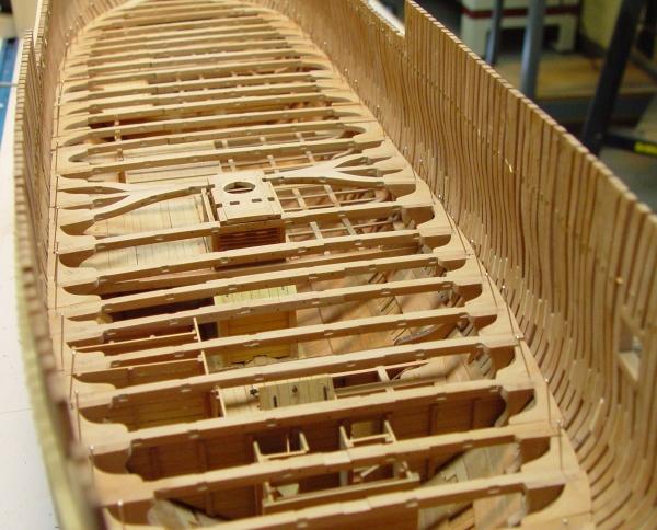
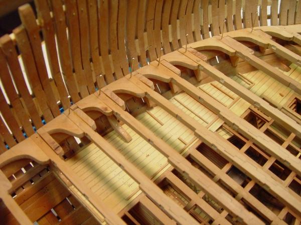
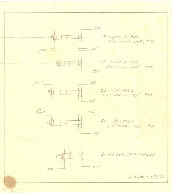
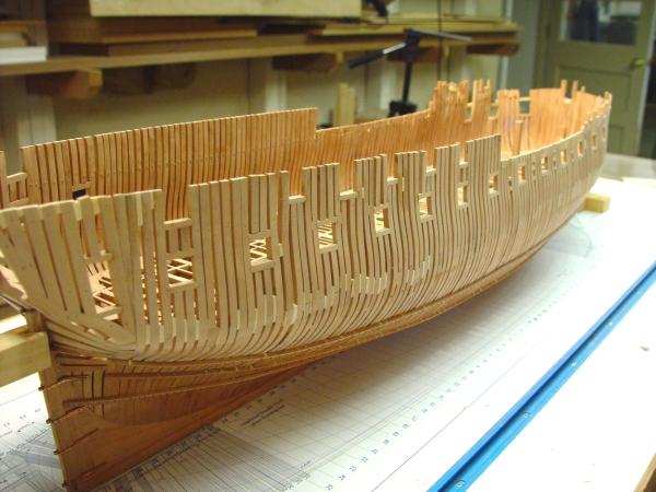
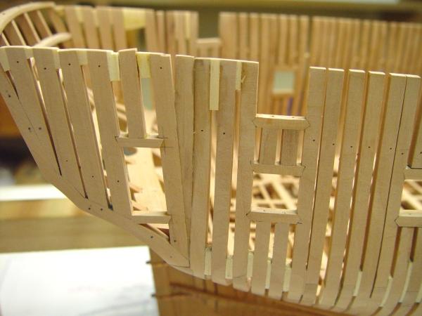
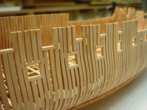
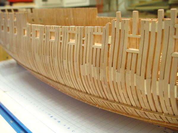
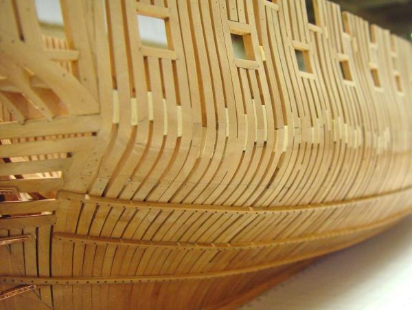
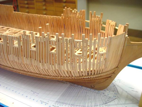
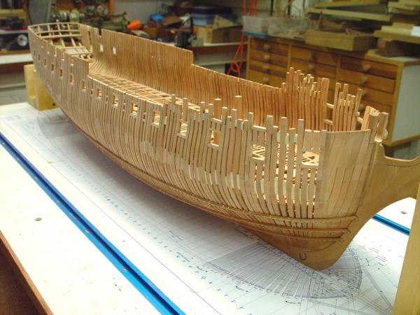
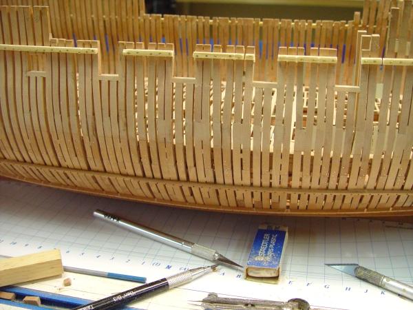
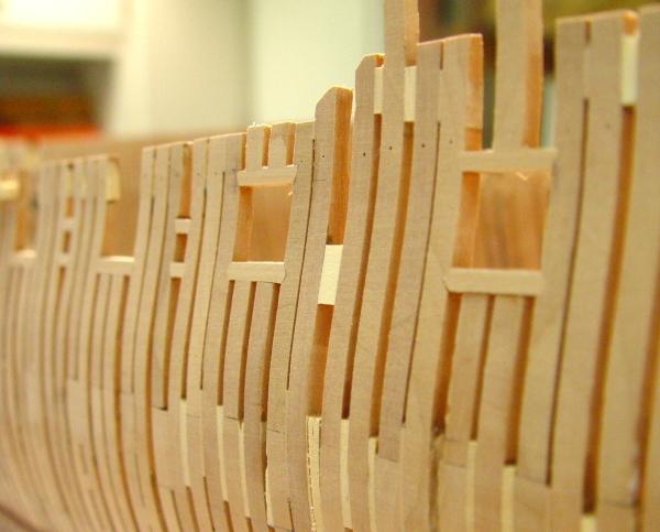
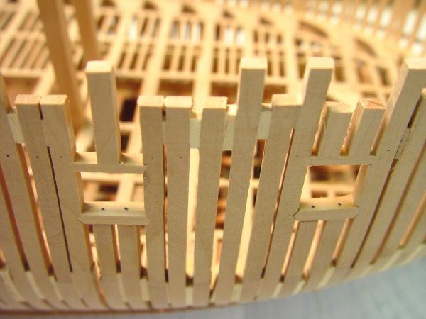
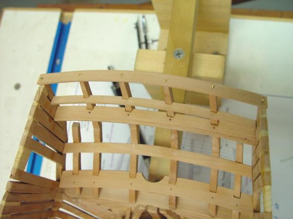
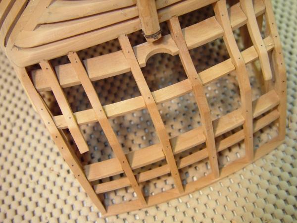
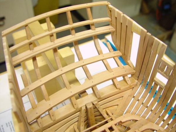
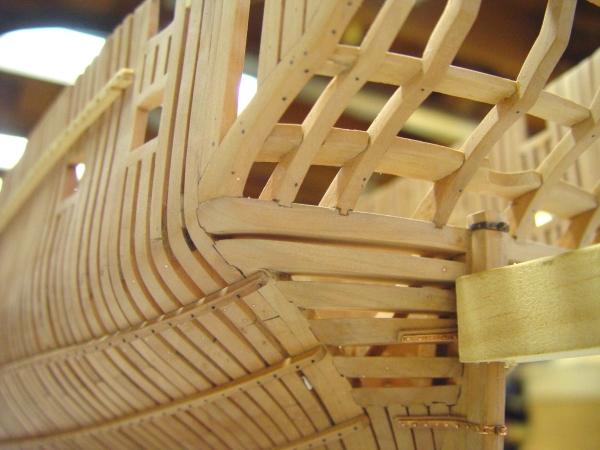
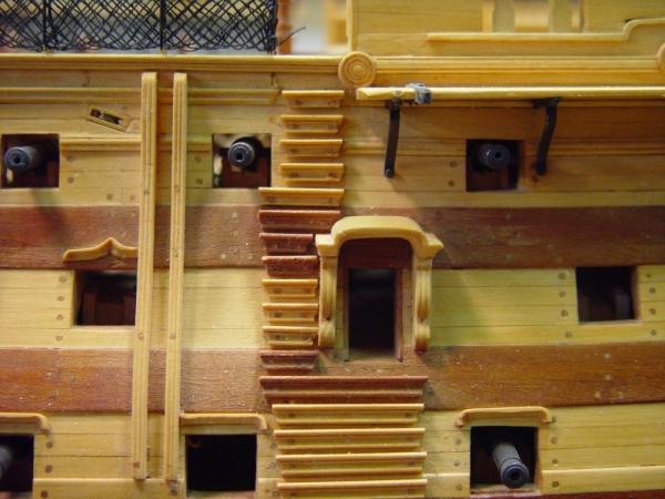
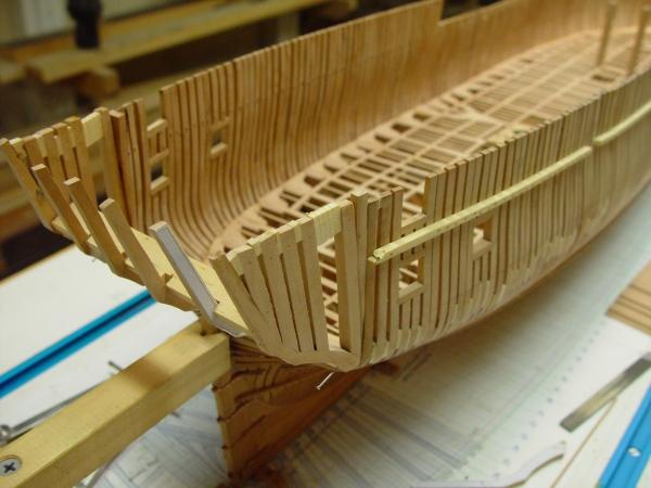
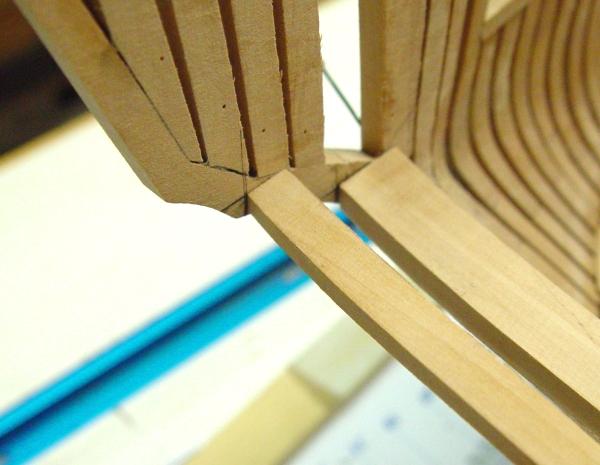
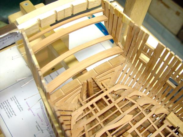
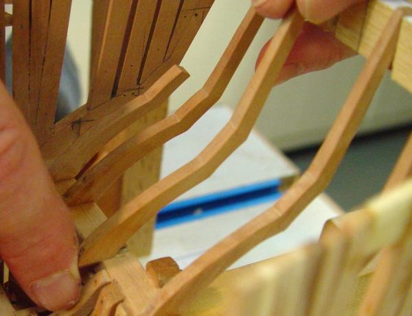
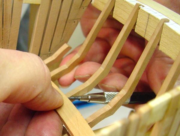
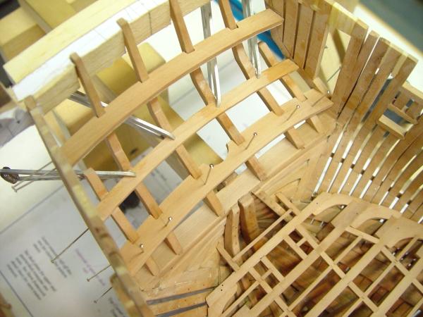
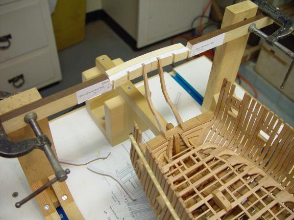
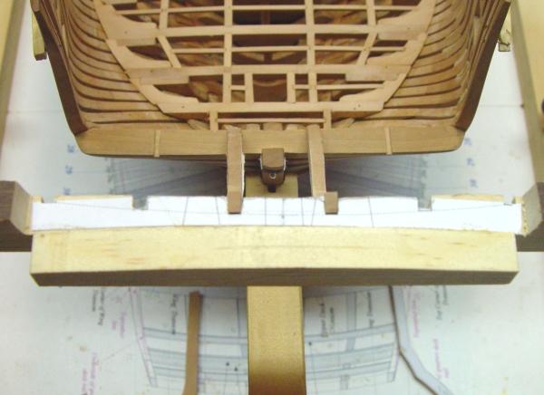
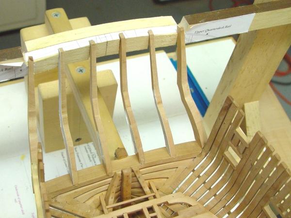
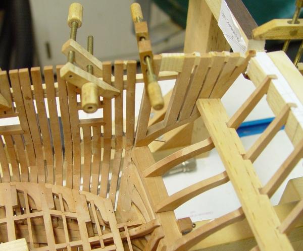
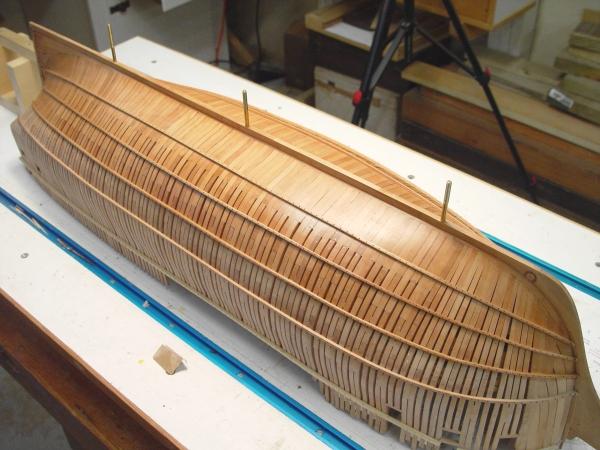
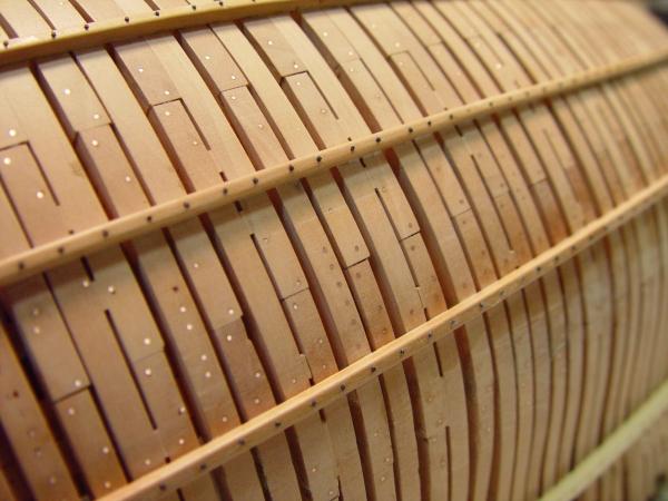
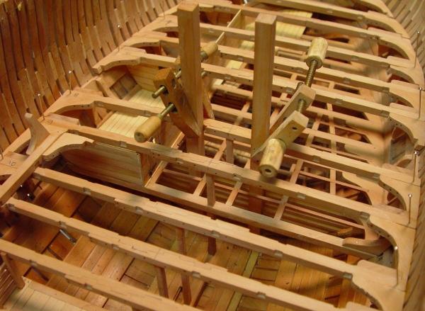
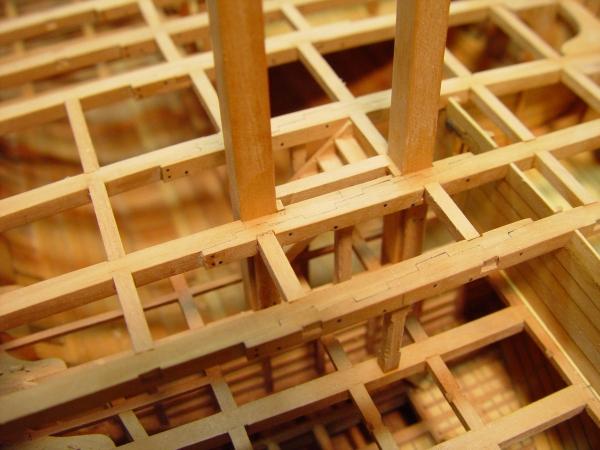
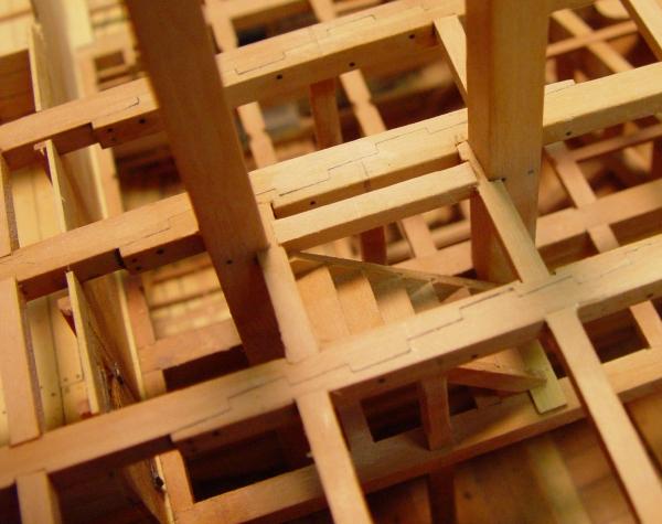
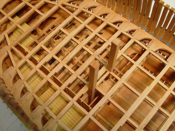
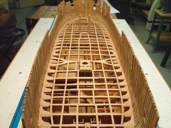
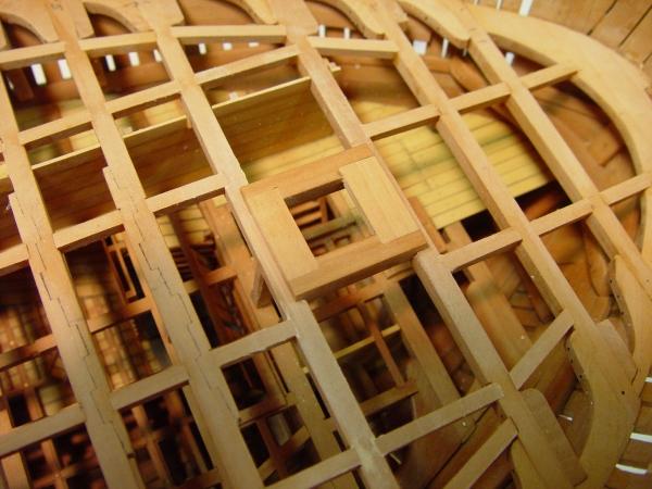
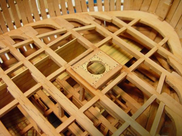
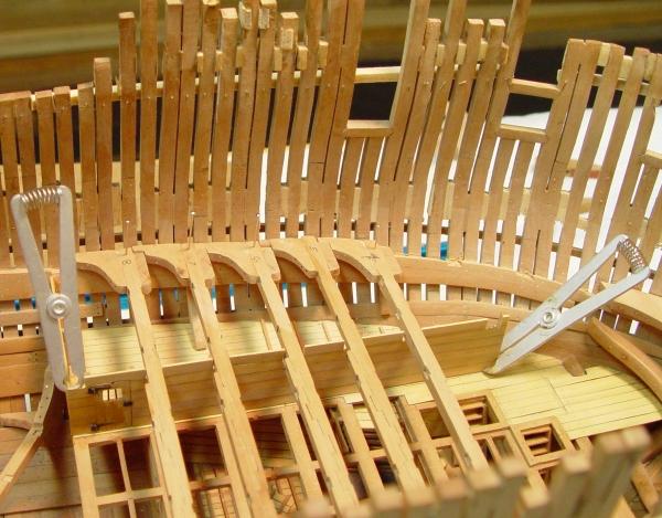
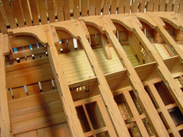
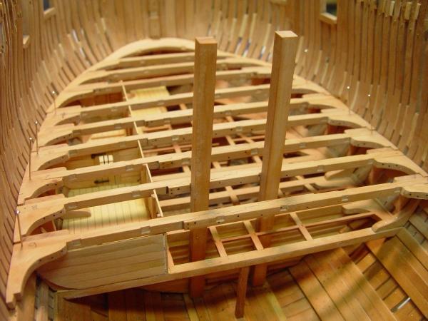
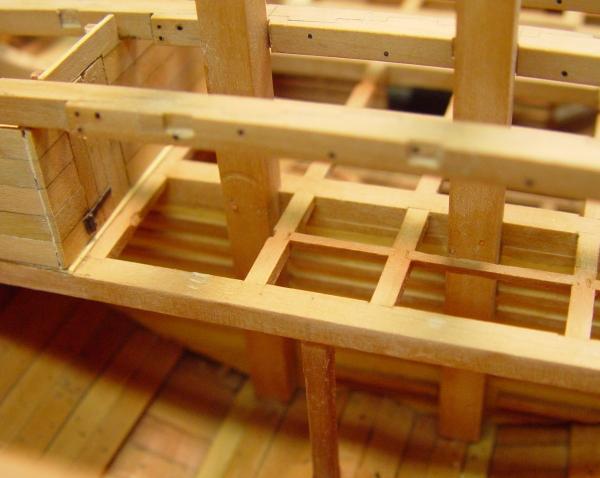
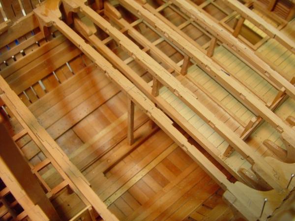
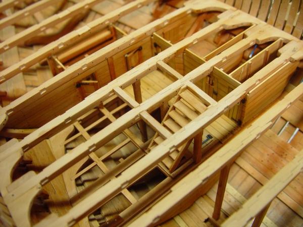
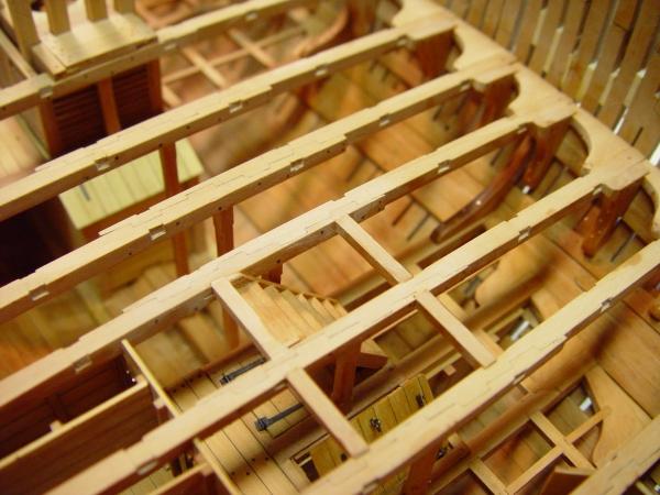
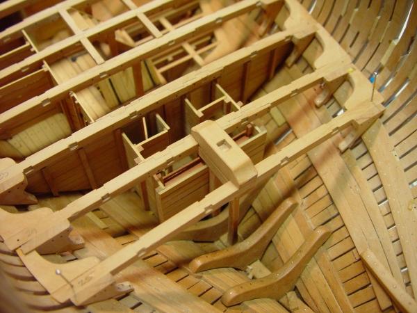
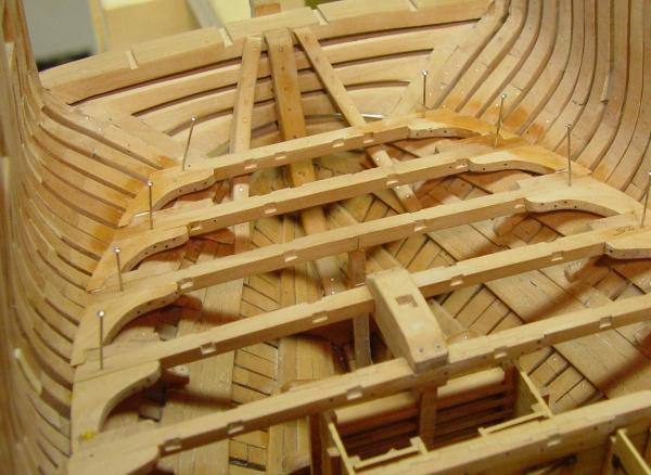
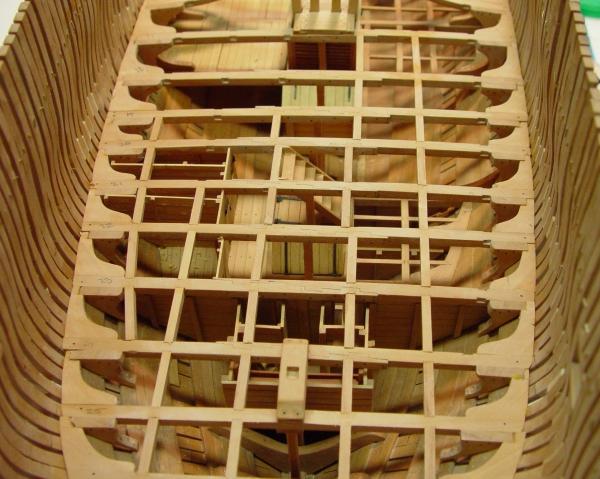
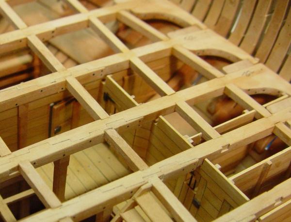
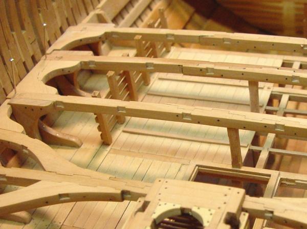
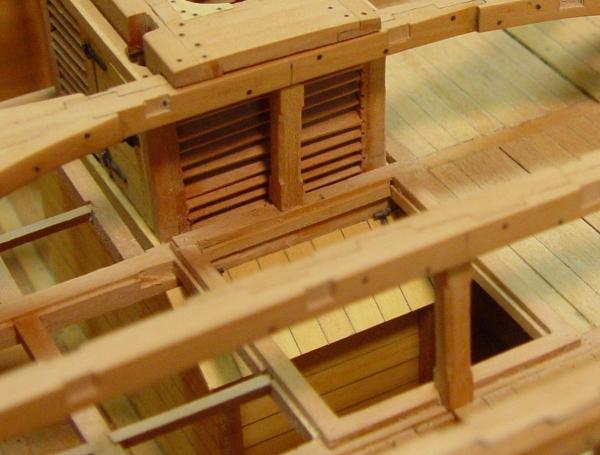
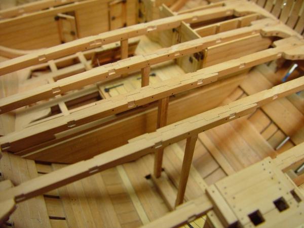
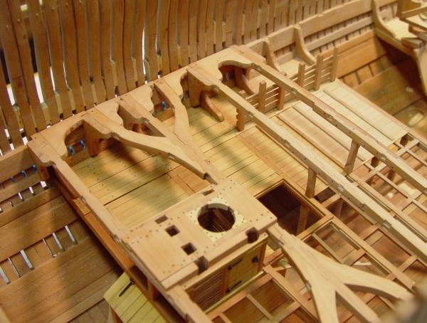
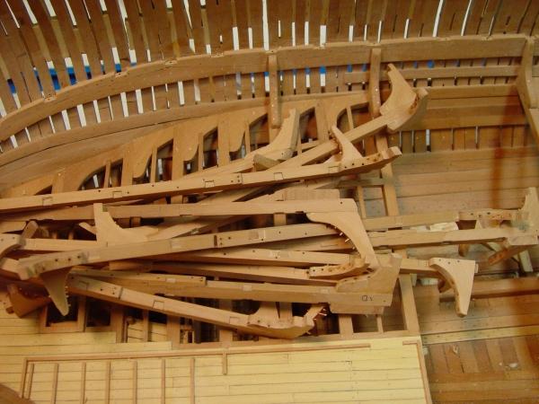
1:60 HMS Naiad 1797 Part 74 –Port Sills 2 Posted 5/7/11 The sills for all the ports on the starboard side were completed today and the hull given a pretty complete sanding to fair out the new pieces. The picture below shows these ports.. The quarterdeck ports are a mix of larger, deeper ports for the four 32 pounder carronades and smaller, higher ports for the eight 9 pounder guns carried on this deck. The tops of the timbers still require some work in the area of the quarterdeck. First the recently added timbers and stubs need their tops leveled off. Also a decision needs to be made on which timbers to take to the full height. Naiads’s drafts show only the timbers framing the ports going to the full height and no “berthing up” of the quarterdeck, but by 1797 it is unlikely that she would have gone down the ways without these barricades. And if she did her captain would certainly have added them to protect himself and his crew on this very exposed deck. The drawings for the model and the model itself at this stage have them all going the full height so the final decision could be made later. A number of other frigate drafts show one intermediate timber going full height and one draft actually shows them all going full height. The next picture shows the opening to the quarter galleries with a new timber on its top sill and this illustrates the work needed to level all these off. The pine spacers will be around for a while here to hold this fragile cantilevered structure from falling off. The next picture just shows more of the quarterdeck ports. Framing these required some departure in the lines of the frames but all is in accordance with the original framing draft. The next picture shows the ports in the waist and the four sweep ports. The next picture is a view from below. Hopefully the unsightly pine spacers at about the level of the wale will soon be gone. The next picture shows the work done on the timbers in the forecastle area. There is an opening at the height of the forecastle rail on each side for the two 9 pounders that round out the 38 gun battery. This did not require a sill, Also, there were two carronade ports on each side of the forecastle and these have been framed in above the first and second upper deck gun ports. The ports nearest the bow are the bridle ports and not one of the 14 on each side that count in making up the battery of twenty-eight 18 pounders on the upper deck. These were a late addition in the design and could be available as chase ports. Naiad, like all the earlier 38 gun frigates suffered from too many guns on too short a deck. The earliest versions, the Minerva Class (1778) and Latona (1779) had a gun deck of 141 feet and room only for 14 ports in total and even these were pushed too far forward and aft. The Artois Class (1793), of which the best-known example is Diana, had a 146 foot gun deck but still only 14 ports. This enabled the first guns to be set back further but in this location were not good as chase guns. Naiad (1795) went to 147 feet and as an afterthought added the fifteenth port, which would normally not be filled, but could be if needed. Even at this longer length, Naiad was given to pitching. It would take a few years, but the best performing classes of 38’s would feature gun decks of well over 150 feet. (The dates are design dates.) The last picture shows the full model from forward. Those with good eyesight and a critical eye will notice a bit of a patch job on the timber framing the aft side of port 2. Replacing this entire timber would have been a very big job and all would have been covered by planking, so I am considering it a field repair of battle damage. So much for perfection. In addition to the port work all the timbers on the forecastle have been cut down to final size on this side – unlike the forrest on the port side. It is now time to move to the unplanked port side, where mistakes cannot be buried. Ed
-
Jeff, thank you for the very nice review of the book. Frank, I hope the book will be helpful to you. I believe that most of the content is applicable to many levels and types of modelling - at least that was my intention. Salvatore, I hope all the things you have made from the book will prove helpful and I wish you well on your project. I hope we can see it on MSW. Ed
-
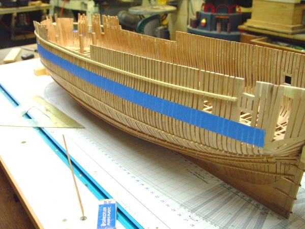
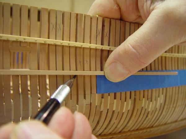
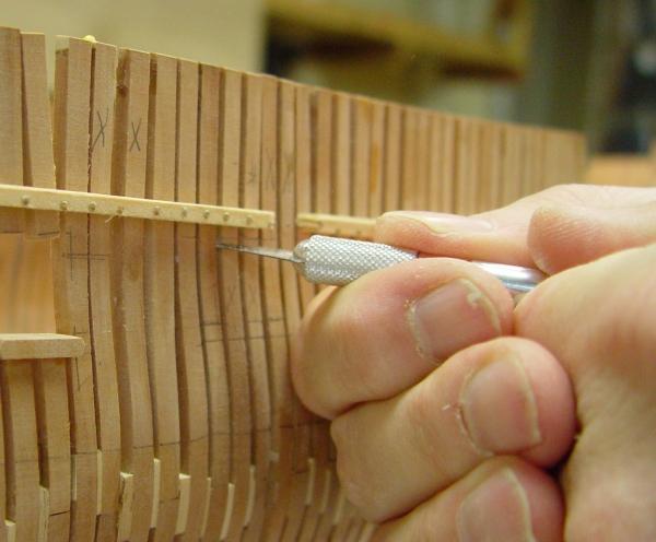
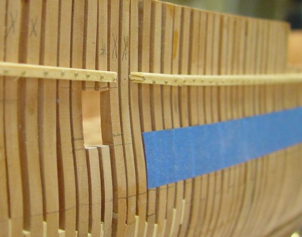
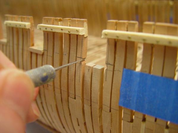
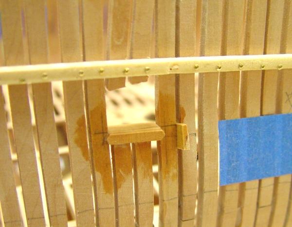
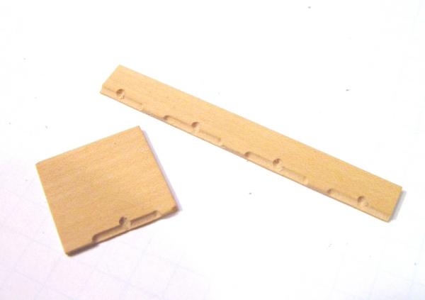
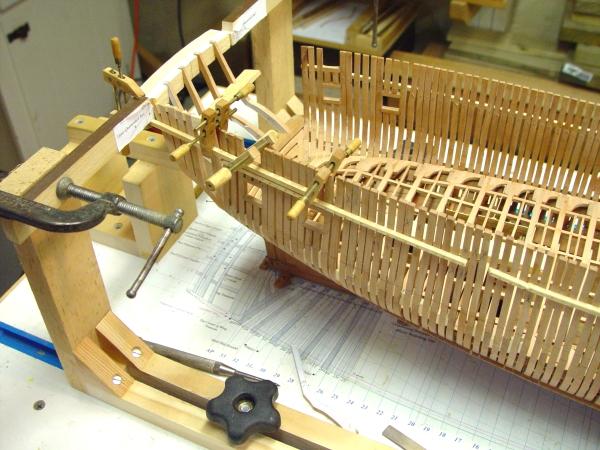
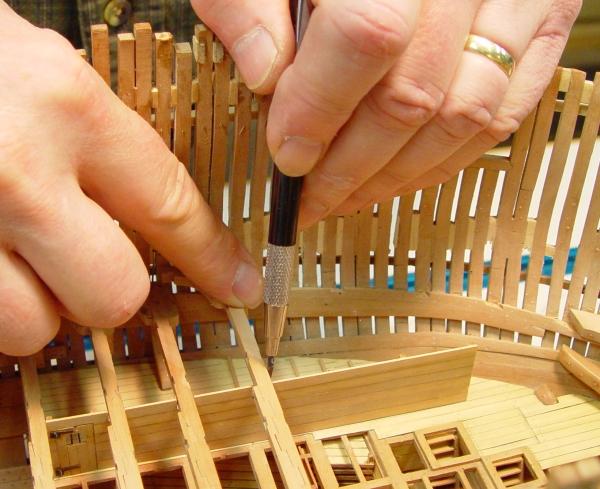
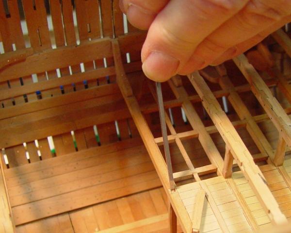
1:60 HMS Naiad 1797 Part 73 – Gun Port Sills 1 Posted 5/5/11 In an effort to finish up the hull framing, I decided to frame the gun ports and clean up the timbers around the forecastle rather than move back to the lower deck. The first step was to mark out the tops of the sills. This was done from the base up and from the topside down as a check. Also from this stage forward I intend to take all measurements from the top of the timbers down to assure that as decks and outside work progress upwards everything will zero in on the topside. Of course the tops of the timbers had to be checked for height. Fortunately there was no appreciable difference when measuring from the base or the topside. The line of the port sill tops was marked with the blue tape as shown in the first picture. This was done on both sides. A few ports had already been framed toward the ends of the ship. At this stage I was still on the learning curve in cutting the joints for the sills, so I elected to start with the starboard side where my mistakes will eventually be covered with planking. In the next step the timbers around the port were marked at the top of the tape with a pencil. The tape around the port was then removed and using a piece of stock that was sized for the lower sills, the line of the sill bottom was marked as shown below. The top of the port was then set off and the two timbers interrupted by the port were cut below this upper line with a small razor saw as shown in the next picture.. This cut did not have to be precise because the timbers above this line will be removed then reinstalled on the top sill. They can be sized more precisely, and more easily before that step. The timbers were then cut on the bottom line of the sill and cleaned up with a sanding board as shown below. In the next step the outside of the joint, the tip of the apex on the sill, was marked using the compass with the extended leg. A horizontal cut was then made with the razor saw to this line in the center between the top and bottom sill lines. The next picture shows how the triangular mortise was cut using an X-acto knife. My original process for making this joint was to use a square file then finish it up with a triangular file, but the knife was much faster, easier and more accurate. The two vertical lines marking the apex of the joint described above can be seen in this picture. The sills were cut from the strip shown in the second picture. Before cutting, the apex was formed on one end usinf a sanding board. This end was then fit into one side and the length marked for cutting off. The apex was then formed on the other side of the sill and hand fit into the joint. It was then glued in leaving excess wood inside and out to be faired off. The next picture illustrates another task that needed to be done on a few of the ports. In this picture a small spacer is being used to bring the port to precisely the correct width. Notice that the pin holding the frame to the ribband has been removed so it can be shifted. I was careful when initially setting the frames to get the right spacing for all the ports, but inevitably a few were slightly off. A rectangular gauge was used to size the port initially and at ths stage. On Naiad all the gun ports are framed with main frame bends, without exception, so on every side of either port these would have had spacers between their two sections over their full height. I installed these on the lower hull but deferred their installation at the top. Now with the gun ports finally sized and framed the spacers of the right size can be installed. The next picture shows some of the ports in the waist with their lower sills installed. The temporary pine ribband is starting to be removed and will be completely gone by the time the ports on this side are fully framed. Having gotten the lower sills done all the way forward, the top sills were started from there back. The next picture shows some of these installed after fairing off. Two of the four oar ports on this side have also been framed in this picture. This picture shows a lot of the temporary pine spacers still in place between the frames. These are being removed as the work inside the hull progresses upward and their purpose is assumed by the permanent planking. Quite al lot of work needed to be done on the timbers at the bow, so that was done as the sills were installed. This involved cutting them down to height and replacing a couple that were too short. I had been putting this off but now it is done – at least on the starboard side. The next picture shows some of this. These timbers are faired pretty accurately on the outside but need wood taken off on the inside to get them down to the final molded breadth at the top. The stubs will need some temporary support for that work. This picture also shows the bolting of the lower sills into the frames. There are similar bolts attaching the stub timbers on the upper sills from beneath. This bolting was done as follows: First the lower sill was permanently installed. Then, when the upper sill was fit, the stubs were glued to their top surface. When the glue dried they were removed and drilled for bolting. The lower sills were also drilled at this time. Monofilament bolts were then installed in the top and bottom sills and the top sills, with their stubs, were glued into place. The stubs were then attached firmly enough to the sills to allow fairing. At this stage the starboard ports are about 75% finished and should be done in a day or so. Ed
-
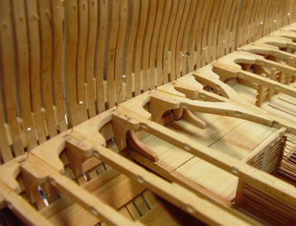
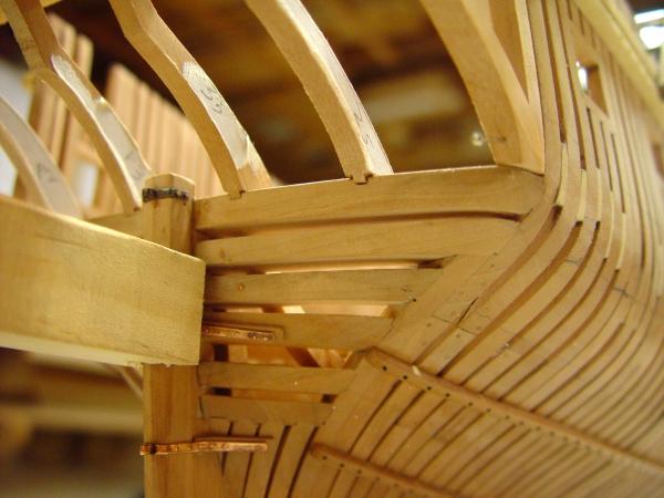
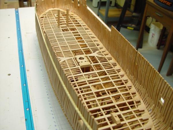
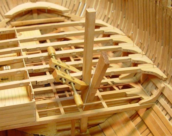
1:60 HMS Naiad 1797 Part 72 – Stern Timbers 3 Posted 5/4/11 Before the deck and seat transoms for the quarterdeck could be installed, the forward edge of the deck transom needed a rabbet on its upper surface to receive the aft ends of the quarterdeck planking. Lines defining this rabbet were scored on the forward and upper faces of the transom and the rabbet was pared out with a small crooked-neck paring chisel as shown in the first picture. The rabbet is 3 inches deep to match the thickness of the quarter deck planking. In the next picture the rabbet is being cleaned up using a diesinkers riffler file. This tool has teeth on the bottom only and the sides taper in, making it a good tool for cleaning up inside corners. This picture also shows the dividers with one leg extended that was used to score the lines on the piece. These scores made the paring easier, preventing tear out on the top edge. The next picture shows the two quarterdeck transoms being glued in place. Before taking the hull to the bench for fairing of the bottom counters and bolting, a temporary cap rail was fitted to protect the tops of the stern timbers. This is shown in the next picture. This rail is nailed in place with small brass nails which can be removed later. The temporary rail will also serve as a drilling template when fitting the final piece. The next picture shows the underside of the stern structure on the bench after fairing, bolting and sanding. The last three pictures show the ship re-mounted on the shipway at this stage, The framing of the hull is now complete, except for framing the ports. This side of the hull will be planked from the wale up, and perhaps some of the diminishing strakes below the wale will also be installed. Pencil lines showing the extent of the wale can be made out in this picture. The pine spacers at this level on this side have yet to be removed. The above picture shows the interior of this structure after completion of the bolting and sanding. The joints at the foot of the stern timbers will soon be reinforced with iron plate straps, but first the knees need to be installed. That will be done after some other work in this area – the lower deck waterways and the two remaining sleepers. The lower deck ports also need framing. This is still a fairly weak structure and it will be so until knees, planking and/or ribbands are added. To help strengthen it, all the bolts were installed to provide strength as well as appearance. This was done by dipping the bolt, in this case black monofilament, in medium viscosity CA, inserting it from one side, removing it, re-dipping it and finally inserting it from the opposite side. This way glue strength is achieved on both ends of the bolt. Medium CA dries slower and so this can be done. Thin CA would be more likely to grip immediately. This picture shows bolting and joints on the underside of the structure. This side of the ship will not be planked so more attention is being paid to sanding and polishing of the frames on this side. Additional ribbands will also be installed up the sides. Holes drilled for pins that will not receive bolts are also being filled on this side with pear treenails. With this final hull structure finished, work can resume on the lower deck. Ed


-
The Naiad Frigate - Addendum 2 Printing Patterns This is not a correction, but merely a note to emphasize the importance of printing the Naiad pattern sheets at ACTUAL SIZE. This may seem obvious, but the Adobe software I use does not always default to actual size in the print dialog box. It apparently opens at the last setting used. To avoid the catastrophe of printing at the wrong scale, the attached pdf shows the correct printing settings on the two common Adobe applications and describes a method for checking the settings. Addendum 2 .pdf Ed
-
MArk, I don't know how you can bear to work on that bench. Its more like a piece of furniture. Ed
-
Hello Peter, Your pdf viewer may set the viewing size differently. My patterns open on my screen at 119%. This has nothing to d with printer setting. All the patterns should be printed ACTUAL SIZE. On Adobe Reader, on the print screen, the Page Scaling should be set to "None". On Adobe Acrobat set the Fit setting to "Actual Size". One way to check the printed pattern is to print a midship frame (like DF A) and measure the moulded breadth at a height between the heights of breadth - the maximum breadth of the frame. This dimension is shown on Drawing 1, the Sheer Plan. It is a basic design dimension. If you have printed the pattern at actual size that dimension should be 38' 9". At 1:60 this is 7.75". Another way to check this on other frames is to measure the moulded breadth of the frame on Drawing 2 or 2b, then compare that to the pattern. Use dividers for this. If measuring widths of bevelled frames be sure and measure to the correct edge. Once you have verified that actual size is the correct setting, these checks will not be necessary. Hope this helps, Ed
-
Greg, Here's a Micromark link: http://www.micromark.com/mini-clamps-with-springs-set-of-5,6467.html They have a limited opening of about 1/4", so are useful only n some situations - but they can be very handy. Ed
-
HMS Victory by EdT - FINISHED - 1:96 - POB
EdT replied to EdT's topic in - Build logs for subjects built 1751 - 1800
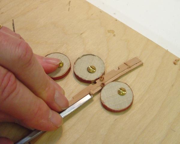
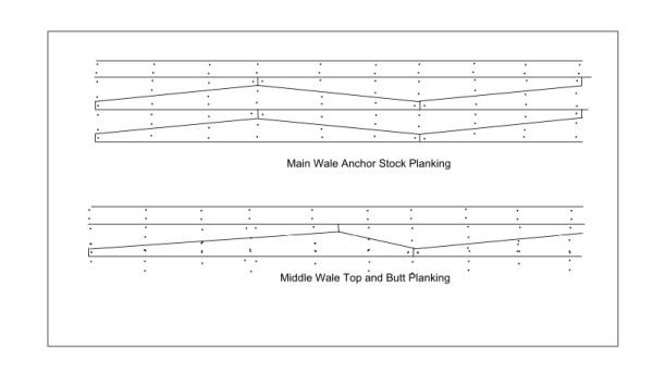
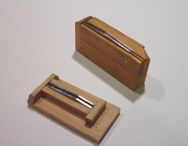
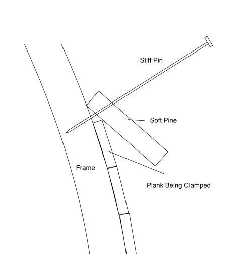
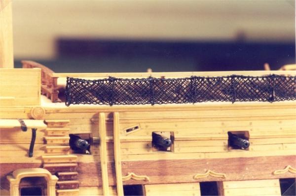
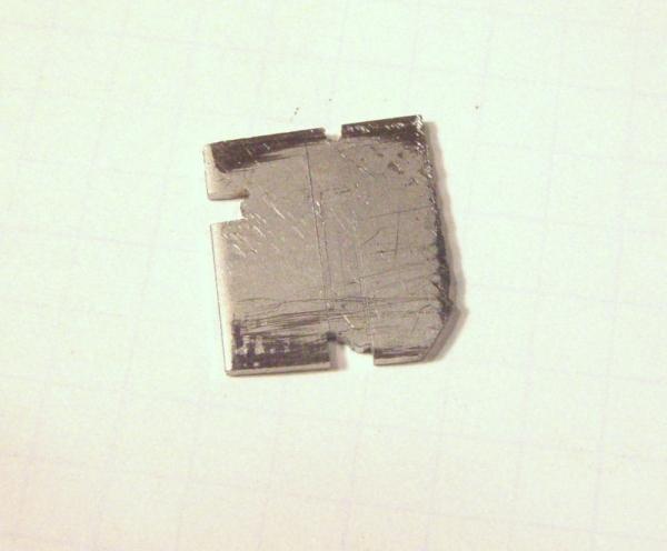
HMS Victory 1:96 Scratchbuild Project Part 6 – The Topside Planking Posted to MSW 8/18/10 In Part 5, we started working up to the task of topside planking by discussing the objectives I had for the final appearance. I like to set these objectives up front for each major stage to use as a quality yardstick when deciding how far to go with each aspect of the work or when to scrap some unsatisfactory work. In this Part, I will cover some aspects of the planking that may be of interest. I will also discuss how the rail moldings and the “rigols” over the gun ports were made. Planking from the lower wale up to the waist rail. The Lower Wale, or Main Wale The main wale is a band of thick structurally important planking that runs from just above the waterline at midships up to the bottom sill of most of the ports of the lower gun deck. Because the line of the lower wale, and almost all of the topside planking for that matter, parallels the sheer line, and because that line has more curvature than the line of the decks, several of the after gun ports on the lower deck actually cut into the lower wale, the aftermost one being almost entirely within the wale. So, before doing any planking of the lower wale, the gun port framing had to be dealt with. Because the gun port sides, tops and bottoms were formed by the ships structure, a collection of Lauan frames and pine filler pieces, the ports needed to be re framed to improve their appearance. This was done by enlarging the port openings and framing their insides with strips of 1/32” cherry. This also provided an opportunity to check the final location of the ports and make any necessary adjustments. Once all the lower deck ports were lined, the planking could begin. Because the lower wale was expected to contribute longitudinal stiffness to the hull structure, its lower four strakes had planks in the shape of anchor stocks, that is, of increasing width from the ends to a point in the center of the plank. The lowest row had the peaks on the top and the second on the bottom and then a repeat for the next two strakes. This provided an interlocking structure which would help resist bending stresses on the hull, specifically “hogging,” the tendency for the ends of the ship to bend downwards as a wave lifted the center of the ship. The picture below describes this along with the slightly different configuration for the middle wale, known as “top and butt”. The picture above shows how this looked on the model. These special shaped planks had to be made accurately or they would not fit together seamlessly, which was quite important to the final appearance. Special devices were made to cut these and the slightly different shapes for the middle wale, in which the highpoint is off center. The tools shown below were used to cut these planks all to the same size. These two slightly different cutting guides, were made by filing steel plates to the correct profile of the pyramidal edge of the planks, making sure their top edges were smooth and accurate. Then they were fitted into wood forms, which set their height correctly and also the length of the plank. Spacing was set to just over the plank thickness for easy removal. The guide at the top right was for main wale planks and the one at the lower left for the middle wale top and butt planks. For use these were secured in a vise. Planks of the final thickness were cut to the correct length and just over correct width, allowing the guides to set the final width. These blanks were each placed between the steel rails and pared down with a sharp chisel flush with the top of the guides. This produced uniform planks with sharp square edges, which fit together well when installed. Planking Procedure All the planking was cut from 8/4 (2”) by roughly 6” wide stock. European Boxwood of this size was hard to come by even in the 1970’s, but I was fortunate to be able to acquire two pieces in this size about 3 ft long. Cherry was not a problem, but it needed to be selected for straight grain from pieces I had. The wide stock was then cut to about 12” lengths, ripped down to the plank width, using a very thin kerf 10” circular saw blade, and then if necessary, cleaned up with a cabinet scraper to assure a very smooth edge on the planks. Planks were then ripped to thickness on the Unimat circular saw, using a relieved fine tooth metal working blade that produced a glasslike finish on the surface of the planks. As I mentioned in Part 5, wales were done in cherry and the rest in European Boxwood. Anchor stock and top and butt were worked in paired rows to make sure pieces fit each other as the rows progressed. To assure tight joints the back corners of each plank was very slightly chamfered with a file to assure that the front faces would touch. Titebond glue was applied to the back and bottom edges – also to the appropriate end if the plank was butting another installed plank. Since the framing and filler on which the planks bedded was solid, clamping was done using short pieces of soft pine about 1/8” thick through which stiff pins were hammered into the frame. Friction between the pin and the pine held the plank down and in until the glue had a chance to set. Below is a diagram illustrating this clamping technique. Excess glue was then brushed off using a wet artists brush kept nearby in a jar of water. This eliminated the need for later sanding or scraping to get the glue off. After 30 years, none of these glue joints has failed and all the planking is still tight. Finally, holes were drilled to receive the treenails. This was done later, when enough planking was complete to draw in pencil the lines of the nails. Holes were then pricked with a center punch to assure that lines of nails would be straight. A drill size just below the diameter of the treenail was used to assure a tight nailed fit. The sharp end of the nail was dipped in the glue, held in the hole using tweezers or small pliers, and tapped in with a small hammer. Excess glue was brushed off and when dry, the surface of the plank was leveled off with a small file. Using a file here assures that the nail head will be flush. Sanding may leave a bump with the hard end grain of the nail. It also tends to ruin nearby sharp edges. Toward the ends of the hull, planks needed to be curved to fit. This was done by cutting the plank to size, steaming it in an old teapot until pliable, then fitting and clamping it in place – without glue. As the plank dries, it will shrink, and if glued, will leave gaps. When the plank was completely dried it was glued in place. Boiling water sometimes discolored the surface of the planks, but I found this could be removed with the file. There are other good ways to bend wood, but this was the method I used. The areas between and above the wales was done in straight boxwood planks using the same procedure as above. This planking was thinner than the wales, so care had to be taken to avoid sanding or filing off the raised edges of the wales. These were given a very slight rounding during the final polishing of the hull exterior. As each strake of planking was completed, a dimensional check was made, by measuring up to the sheer line to make sure the height was correct along the hull. Discrepancies when found were very small and could be corrected easily with a file or small scraper. Doing this at each strake avoided a potentially nasty surprise when the planking ultimately reached the sheer line. Finally, before beginning the next strake, a triangular file or scraper was used to remove any fillet of glue left between the top of the planks and the frame to assure next strake would seat neatly. Where planks ended at a gun port, they were left slightly long, then filed flush with the frame later. Where a gun port sill or lintel cut into the edge of a plank this was also filed out later. This assured a nice sharp corner to the port openings. Rails The picture below shows the three rails the run the length of the hull above the upper wale. The lowest is the waist rail, which in this picture is cut by the line of the upper deck 12 pounders. Above that is the sheer rail, which is in line with the fore, main and mizzen channels, and above that is the planksheer rail, which runs under the planksheer at the waist. There are additional “drift” rails aft and forward. These rails add interest and accentuate the lines of the hull. The upper two have a similar profile. The waist rail is different. These rails were shaped in Boxwood, using a profile scraper which was drawn along the edge of a strip of wood with thickness equal to the width of the wale, but much wider so it could be secured in a vice while being shaped. After shaping the rail was sliced off on the circular saw. These rails were bedded on the framing, not on top of planking, so they replaced a row of planks. Actual practice may have differed, but this seemed a logical approach on the model. A picture of the profile scraper used for some of these different shapes is shown below. These profile cutters are easy to make and do a nice job making moldings. The above cutter was used for the sheer rail, the steps up the side and the cap rails on the channels. The cutter is made by marking out the shape on the metal with a sharp scriber, then sawing out the rough shape with a jewelers saw. The shape can be dressed with small files, but very small parts of the shape were done with the saw alone. Very fine blades are available for these saws. Small files made for sharpening Japanese style saws have very sharp sides and work well. I made my cutters from some 1/16” stainless steel plate I had. Cutters like this were also used for things like the fenders shown in the picture below and for making rigging blocks, which I will discuss later. ]The picture, above, shows some of the other detail that was added after completion of the topside planking – the molded steps up the side, the elaborate middle deck entrance way, the two vertical fenders to protect the hull when loading barrels, the “wriggles” over ports to divert water and the sheave set into side which would later take the mainsail sheet into the waist. The scrolls at the ends of the drift rails were made by turning grooves on the end of a boxwood dowel. This was a compromise I have regretted. They needed to be carved as a scroll with decreasing radius to the center, but I gave up on this too quickly and took the easy way out. I have never been happy with this decision. Port Rigols The rigols over the ports presented an interesting problem. There are two types. On the lower deck ports they are straight across the top and on the middle deck they curve up into a point at the middle. The undersides are concave curves. The challenge was to make them proportionately correct and to have them uniform. Both were made starting with a strip of boxwood the thickness of the horizontal thickness of the rigols and maybe 3/8” wide. The inside concave shape was cut along the face of the boxwood strip near its edge with a small ball end mill to make a rounded slot of the correct length and depth for the interior curve. The depth of this milling cut left about 1/64” of wood at the bottom. Several slots were cut along this line on the strip. The circular saw was then used to slice off enough so that only the top half of the slots remained on the edge of the strip. Then the inside lower 1/64” edge was trimmed back to its profile with a knife. Then the strip of “wriggles” was sliced off above the slot leaving a strip with quarter concave slots on one edge. The rigols were cut off to length and the outside curve at the ends shaped with a chisel. The middle port wriggles were done the same way, except before slicing off the strip the upward interior concave pointy shape was cut with a small gouge. The strip was parted off, the pieces were cut to length and the top curvature carved manually. The picture below, of some leftover work-in-progress pieces I found, should help clarify this explanation. In this picture, initial milling of the some middle deck rigols has been done and the bottom half of the slot sliced off. The next step would be to shape the interior curves with a small gouge, then trim the lower edge inside the curve to match that shape. Next, the strip would be sliced off and the pieces cut to length. Then the top edge would be shaped to match the curvature of the inside. In Part 7, I will address what I felt was some of the most difficult woodworking in the ship, the complex curved rails and supports at the head and also the detailing of the head back to the forecastle bulkhead, which was easier. Cheers, Ed Tosti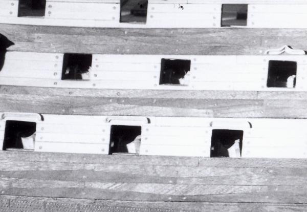
-
1:60 HMS Naiad 1797 Part 71 – Stern Timbers 2 Posted 5/2/11 In Part 70 the side framing assemblies over the stern timbers were being installed. In the first picture these assemblies on both sides have been glued on and are waiting for bolts. The support fixture was removed so these could be more easily faired inside and out. Before installing the inner stern timbers, I wanted to fit the upper transoms. The timbers would then be installed so further work on the transoms could proceed. Before beginning this work, however, I needed to do some research and rechecking of my drawings of this area and this resulted in some re-drafting and re-lofting of the patterns for the four upper transoms. I also took the occasion of these refinements to replace the plan that is attached to the building board. For these reasons it has taken a little time to get this installment posted. In the next picture the upper deck and seat transoms have been cut out and fit between the side timber assemblies. These round up and aft. The upper convex surfaces were cut out of thick stock from the patterns using the scroll saw and then sanding to the line on the disk sander. The thickness and the lower convex surface were done on the thickness sander in the way the bottoms of the lower deck beams were done. The next picture shows the way these were located on the side framing before fitting. The vertical pencil lines at the aft side of these were squared up from the corresponding line on the new plan on the board. The horizontal lines for the top surface were transferred from the framing elevation drawing, which also underwent some revision, and measured up from the base. The deck transom is of course at the height of the underside of the deck. The top of the seat ransom is on the line of the tops of the gun port sills and is actually the sill for the upper deck stern chase ports. The next picture shows all four transoms fit up and pinned in place. With this done the stern timbers could be installed permanently. This is being done in the next picture. With glue applied, these were slid into their dovetails from the front. The next picture shows these in place supported by the fixture, which has been re-mounted for the purpose and for the following steps. The next steps involved some complicated layout and joinery, cutting the notches in the bottom of each transom so it could be let down on the stern timbers. With the transom held approximately in place the line of the joints is being marked. The first of these, the upper deck transom, turned out to be the most troublesome. Because of the slants of the various faces and the curved top surfaces of the timbers it is difficult cut these to fit tightly. I will pass on describing all the gory details, but after some hours of work the first piece was not satisfactory. However, it was quite useful in laying out the lines on the second attempt. This is shown in the next picture from below, a much better result than the first one. Trust me. The lower faces of the stern timbers still need to be faired in this picture. That will be done when all the transoms are installed with all their bolts. The remaining three were done on one try and the next picture shows the lower three in place with the lower two pinned and clamped after gluing. The holes for the pins holding all these pieces in place will be filled with the permanent bolts. A corner of the nice clean new drawing on the board is also somewhat visible in this picture. Ed


-
1:60 HMS Naiad 1797 Part 70 – Stern Timbers 1 Posted 4/26/11 I decided to install the stern timbers next, because they are needed for both the upper deck framing and also for the installation of the wale. First an alignment fixture for the top of the stern timbers was made from a strip of scrap pine using pieces extracted from the drawings. Being able to cut paste and print extra copies or fragments for patterns really comes in handy. The center section is curved up and aft to match the stern round up and round aft. Notches were then cut at the locations of the tops of the stern timbers so they would fit in place snuggly. The first picture shows this pattern held in place on the two clamped squares. The pattern was located carefully, squaring up from the plan on the board and setting heights from the framing plan. The next picture shows the round aft on the pattern. The notches were cut to the line of the outside of the timbers. The next picture shows all six full timbers in place. Except for the outer two they are dovetailed into the wing transom. The outer timbers and the filling timbers in the space up to the aft fashion piece were made offsite as a prefabricated assembly. The next picture shows this fabrication in process. Again, a drawing fragment was cut and pasted to form a template sheet, which was then printed, cut and used as a base for the assembly. The sidings of these timbers are oversized to allow some movement in fit up. They will then be faired back to the shape of the hull during and after assembly. The sills for the doors to the quarter galleries will be fitted later after all this is installed. The next picture shows the starboard assembly clamped into place during the fit up process. A fairing strip of pine is being used to align the assembly. It is clamped just above the strip put on earlier at the sheer line to align the upper timbers. The next picture is a view of the same setup from the inside. This picture shows pine spacers glued between the filling frames to give the assembly enough strength to withstand the heavy sanding in the fairing step. These will come out later. The picture also shows a temporary pine pattern piece crosswise at the height of the touch of the upper counter, right at the base of the upper staight sections of the timbers. This is to assure the correct spacing of the timbers at that level. If just held at the bottom and top they can end up twisted, throwing off the spacing at the center. A third constraint assures that they will be at the right spacing at the all-important level of the stern lights. The next picture shows the foot of the outside timber on the wing transom, roughly faired and pinned to the aft fashion piece. Bolts will be put in between the filling timbers and the outer stern timber before overall assembly to give more strength to the assembly which now is just held with end grain glue joints.. All the stern timbers were made in one piece to simplify things. I will probably scribe the scarf joints on the outer ones to show how they were made in practice. There is still work to be done on the four inner timbers and their joints. The last picture shows the current status from further back. The port filling frames assembly is still on the bench at this stage. When both assemblies are fit up, the next step will be to clean up the inner timbers and then make the four “upper” transoms, the upper deck and quarter deck transoms and the seat transoms for those decks. I may then install the taffrail to give this structure more strength at the top. The basic structure of the hull framing will then be finished – a big milestone. Ed

-
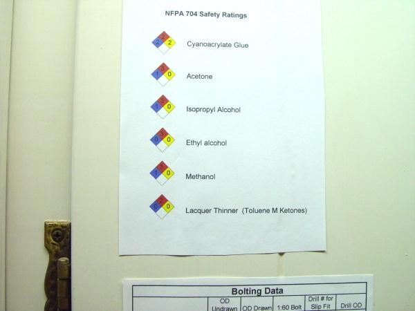
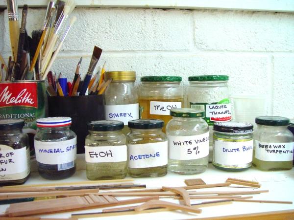
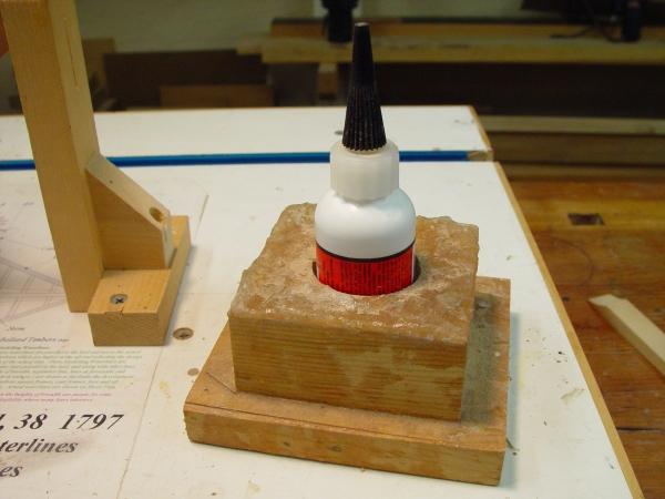
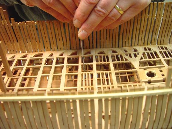
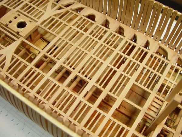
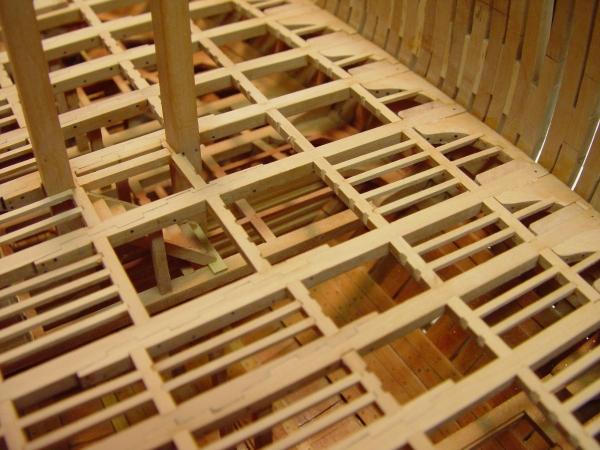
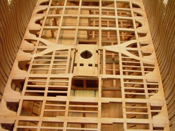
1:60 HMS Naiad 1797 Part 69 –Material Safety/ Ledges Posted 4/23/11 The discussion of the last couple days on finishing has been interesting and I am glad to see others have found it useful, even to the extent of trying out some of the things discussed. It has also left me a little bit uneasy on the issue of materials handling safety and so I wanted to comment on that before discussing the wrap up of the Naiad lower deck ledges. I believe the major health risk in the shop, apart from tool injuries, is wood dust and we have discussed that and dust collection earlier in the series. Solvents and finishes also carry health risks and I will discuss that below, but next on my worry list is flammable materials in an environment where there are sources of ignition – electrical devices, light bulbs, torches, etc. The first picture was taken this morning while I was thinking about this. This is a chart of NFPA 704 Safety Ratings for materials I commonly use. I keep this posted as a reminder to take appropriate care. For those not familiar with these symbols, the blue represents health risk, the red flammability and the yellow reactivity. Zero is innocuous with 3 being severe. You will see that cyanoacrylate glue with a 2-2-2 rating is up at the top. The other solvents have mostly a 3 rating on flammability. So, the point is that there is a flammability hazard if these materials are not handled properly. There is plenty of warning text on the containers for these materials and they should be read and followed. I make sure the containers I use them in have tight lids and are labeled. To prove it here’s a picture, also taken this morning. Jars like this should be kept closed when not in use. When in use there should be ventilation, they should be kept away away from electrical devices and especially away from any torch activity – and by the way, no smoking. Cyanoacrylate in droplets is pretty innocuous unless you glue your fingers together, and it is flammable, but with a reactivity rating of 2 it needs some special care. You don’t want to spill a bottle of this. I have done it and watched the rag it fell on start smoking. (Clean up is no fun either.) I now keep the bottle in the base shown below. This helps avoid tipping over the bottle, which is sometimes necessarily open when in use. Finally a few words on health risks. Overuse of the word “toxic” is a hot button for me, because this term can be applied to almost anything and so it tends to be ignored or unduly frightening. The NFPA chart above puts most of these materials in class 1, mild skin or respiratory irritants. But even this is a relative term and doesn’t deal with chronic, meaning long term, risks. I suggest that if you are using these materials or any others that may be harmful, that you look up and read the Material Safety Data Sheet (MSDS) for that material so you actually know what you are dealing with and how it might affect you. These are readily available online. Just search for, example “Acetone MSDS.” There. This is by no means thorough, but now I feel better. So, back to progress. The ledges on the lower deck have occupied most attention during the past several days. This has been easy work, if a bit tedious. The first picture shows the method for cutting the seats for the ledges in the carlings using a rectangular warding file. The ends of the 4” X 3.5” ledges are then beveled to fit the seats and glued in. The next picture shows the finished area forward of the main mast. In this picture the first tier on the starboard side is being left out for improved visibility of the lower hull. Also, since the outer tier on the port side, the tier that involves the lodging knees, will be completely planked over, I probably will leave those out as well. The next picture shows these installed on the starboard side where all the framing will be exposed. The next picture shows a different view of this area. When these pictures were taken the deck structure had been sanded and rubbed down with steel wool. I didn’t take a picture of the mess that made below. The last picture shows the entire deck. The areas left open for viewing below can be seen better in this picture. As much framing as possible is being left open in the forward area over the detailed magazine, but this is becoming harder to see already. I’m glad I have the pictures of it. I’m still thinking about the next step. It may be to install the stern timbers before getting into internal work leading to the upper deck. Happy Easter, everyone. Ed

-
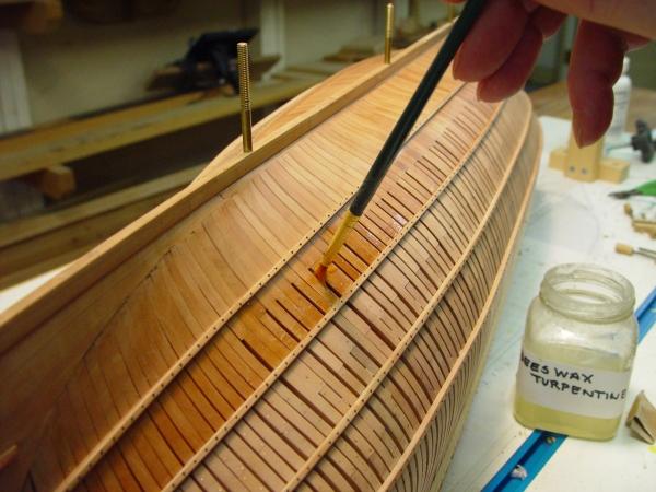
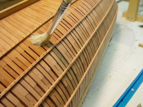
1:60 HMS Naiad 1797 Part 68 –Finishing/Lower Deck Ledges Posted 4/21/11 I have mentioned finishing with beeswax dissolved in turpentine on a couple of occasions, so maybe some further discussion at this stage, when the finish is being applied to the lower hull, would be appropriate. The first picture shows this solution being applied with a brush to the lower framing. The idea behind this finish is to impregnate it into the wood without build-up on the surface, hence the thin turpentine solution. This is made by dissolving solid beeswax in warmed turpentine to a very thin mix. Both these are natural products and I am attracted to them at least partly for that reason. I much prefer the pine-derived turpentine to mineral spirits and other petroleum distillates - for this process at least. The turpentine penetrates the wood and takes the dissolved wax in with it. When it evaporates out, the wax is left. I have used penetrating polymerizing oils, like tung or linseed for many years in various furniture finishing applications, but I prefer the wax for this application. Excess wax left on the surface, especially in tight places where it is hard to rub out, is easier to remove than excess dried oils. A dry Q-tip, bristle artist’s brush or a bit of rag will do the job and if not a bit of turpentine will redissolve the wax and help remove it. This problem with oils can be mitigated by thinning them before application, but they still have a tendency to ooze out later and harden on the surface. Also, since they are cross-linked polymers, they are not easily removed with solvent. Oils also have a more yellow hue that on pear comes out a bit more orange than I prefer. In the picture below a dry bristle brush is being used to buff the surface and the crevices and also to distribute any excess finish. As the finish dries, it lightens to a shade in between the finished and unfinished colors in the above picture. Sometimes when first applying this, light spots show up where not all the glue was washed off, so while doing this, I keep a small bit of 400 wet-or-dry paper handy to sand these areas while applying finish. This removes the glue film and it becomes unnoticeable. Of course once this stuff is put on glue will no longer adhere. The following pictures show the finished lower hull about an hour after application. More finish at this stage will add sheen. Wiping with turpentine on a damp rag will reduce sheen. With this work on the lower hull finished, it was time to return to the lower deck – and the ledges. At the time of this writing the lower deck ledges are about 50% complete. The next picture shows how far they have progressed from aft forward. The inner tier of ledges on the starboard side will be left off and some others, to improve visibility into the lower decks. At least part of the starboard side will be decked, but generally ledges are being installed on that side anyway so I can decide on the decking later - except for the outer tier which will definitely be decked over. The last picture is just the same area from aft. Spring chores are starting to cut into modeling time. It will be a few more days, at least, before the ledges are finished. Ed


-
john, Thank you for your comments and the book orders. Although the book and especially all the drawings and patterns are focused on Naiad, I had always intended it to be much more general with a strong emphasis on methods. As you have probably noticed, there are very few references to Naiad specific dimensions. These are provided on the drawings and other documents on the CD. This was intentional, to leave more room for process descriptions - including pictures of the steps - as well as to make the book more general. Of course. I also wanted to make space to discuss historical construction methods. I am very glad to hear that this is useful to you on your non-Naiad project. Ed
-
Micheal, I have had these for a very long time and can't remember where I got them. I have not seen either since. I may have gotten the broaches from Micromark. I have two of these small files and rarely use them. I'm afraid of breaking them so I save them for when I really need them. One is round the other square. Have never seen these since I bought them originally. Sorry I can't be of help. Here's a link to a supplier that has a lot of small tools. Maybe you can find something here: http://www.ottofrei.com/Broaches-and-Pin-Punches/ Ed
-
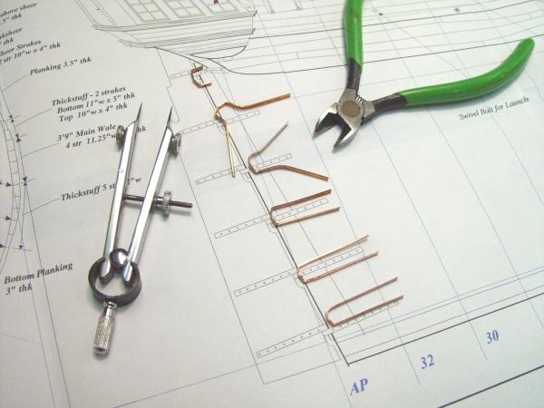
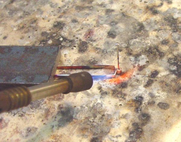
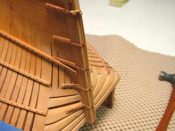
1:60 HMS Naiad 1797 Part 67 –Rudder Braces Posted 4/15/11 The last remaining task on the lower hull before applying finish, was the installation of the braces for the rudder. There are six of these. Except for the top one, which was often iron, these were mixed metal – basically bronze. On the model they are made from copper sheet and hollow rod, treated with ferric nitrate to give them a bronzy patina. In the first picture the stern post is being bearded using a Stanley No. 92 Plane. I find this tool, in spite of its large size, to be very useful for a variety of model tasks. It can be adjusted very precisely to give very thin consistent shavings. After bearding back each side with the plane, the post was dressed off with a file and the brace slots re-cut – also with a file. The next picture shows the straps for the braces cut and bent roughly to size. The stern post widens from bottom to top, so each of these is a different size. These pieces will have a short cylinder made from copper rod silver soldered to it. The next picture show one of these being soldered. The rod segment has a hole, which will later be enlarged. It is made of two pieces of telescoping rod, which had been previously soldered to form one with a thicker wall. A groove was then filed down one side of this to match the apex on the strap. Individual pieces were then sawed off. The hole allows the pieces to be pinned for soldering and also gives a center point for later drilling. Only one pin out of six got soldered in. After soldering the pieces were pickled in white vinegar and appear as shown below. After pickling, larger holes were drilled and the pieces cleaned up with a file. The holes were then enlarged to the final diameter of 3 inches using the very small file and the broaches in the picture. The final sizing in this way allowed the hole location to be adjusted to the center of the strap. This corrected any small misalignment when soldering. The straps were then cut to final size, drilled for bolt holes, filed smooth and polished. They were then treated by heating and applying a ferric nitrate solution to give them a slight brownish patina. My use of this solution is still in the trial and error phase, but I like the permanence of it and the ability to go all the way to black by varying the heat and concentration of the solution. These parts were only slightly colored. They were then given some additional polishing. The next picture shows 4 of the six installed. Small pieces of wood of planking thickness have been inserted under the straps, since this part of the hull will not be planked. Bolts are made from stretched 22 gauge copper wire, cut to a length, driven into predrilled holes, the clipped off and peened over. The long brass rod in the picture was used to maintain the hole alignment so the rudder, when installed, will not bind. The next picture shows the last brace ready for nailing. And the last picture shows all the braces installed. The top brace has been blackened more completely to represent iron. The lower hull is now ready for final polishing up and finishing. Ed


-
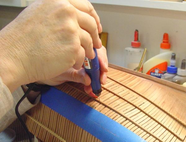
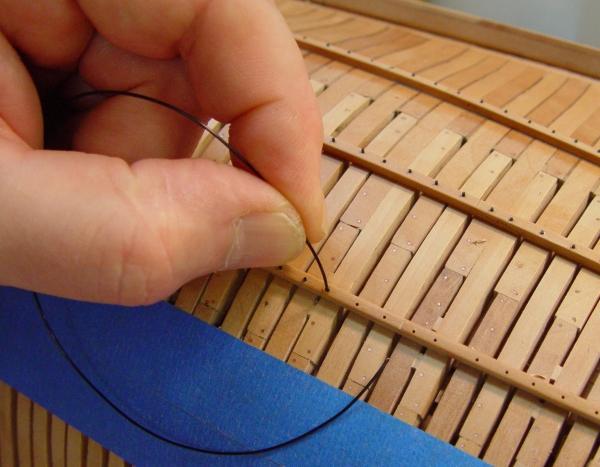
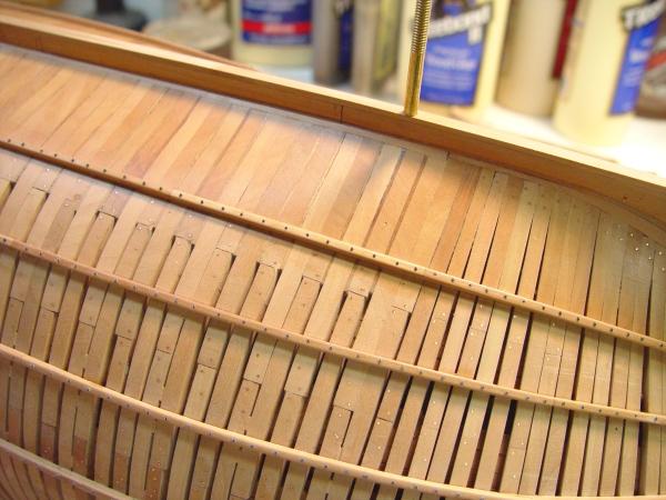
1:60 HMS Naiad 1797 Part 66 –Bolts and Ribband Nails I needed to get outside of the hull and get some fresh air so I took a day to install the remaining iron nails in the ribbands. I had held off doing this because I intended to use blackened copper and I did not want a lot of handling to rub off the black, but with the decision to use black monofilament this was no longer an issue. In the first picture I am enlarging and deepening the holes that were drilled in the ribbands before they were installed. The first holes were done in the drill press after marking the frame locations to assure the holes were centered on the ribband. This was covered in an earlier part. In the next picture the black monofilament, which has been dipped in medium viscosity CA is being inserted into a hole. These holes go part way through the frame. The filament is moved in and out to help move the CA deeper into the hole. The blue tape in these pictures is being used to mark the bottom of the thickstuff below the main wale on this side. I may elect to install that planking below the wale and if so do not want to install structural bolts in the location of that planking until it is installed. This is so the bolts will come through that planking, as they should. Before cutting off the filament the excess CA was wiped off with a bit of paper towel. The filament was then cut off above the surface as shown in the next picture. When all the bolts on the ribband were installed in this way, they were sanded down to a uniform height with 320 then 400 paper on a sanding stick. This does not make them rounded, but it does level them out. The result can be seen in the next picture. The area above the uppermost ribband in this picture (actually below it), has been given a coat of wax, but nothing else in this picture has been finished yet. The sheen on the bare wood is the result of sanding to 320 grit and buffing with 0000 steel wool. Steel wool does a great job on hardwood but it is messy to used in the finer grades because it leaves steel fibers everywhere. These need to be blown out of the model, wiped off steel tools and vacuumed off the floor. The difference in the state of the finish can be seen more clearly in the next two pictures. In this picture the upper band has had a few treatments of beeswax in turpentine. The next two have been pretty well buffed and beyonf that just some sanding. I am trying to follow the construction work progressively with finish in a way that will avoid getting wax on areas that may still need to take glue. This is more important inside where lower areas are becoming harder to reach. Once the braces for the rudder are installed all the levels of framing in this picture will be finished. The next picture just shows more of the bottom. The lower hull is starting to look finished. The other work that was done at this time was to finish off the bolting of the lower deck knees from outside the hull. The next picture shows some of that. There are a lot of copper bolts in this picture that appear to be randomly located. However, most fall into three distinct categories. First are the frame bolts, four at each frame joint, which were put in some time ago. Then, there are the lower deck lodging knee bolts. These can be seen running in a horizontal line just above the lowest ribband in this picture (actually just below it since the hull is inverted). I put in only one per frame. There were actually more. The last category is the lower deck hanging knee bolts. These can be seen running in vertical lines up the frame. One set of six is located just below the center of this photo. I imagine the bolt density in this area would have been about twice what is modeled here. If all this looks confusing from the outside of the hull, it is. Ed


-
1:60 HMS Naiad 1797 Part 65 –Lower Deck Structure Continued Posted 4/11/11 With the riding bitts bolted into place the installation of beams could march toward the bow. In the first picture beam no. 8 is being glued, pinned and clamped into place. The clamps are fixing it to the riding bitts. As soon as the glue was dry two iron through-bolts were installed between the beam and each bitt. Having done that the framing around the ladder way to the forward platform and the staircase could be installed as shown in the next picture. It seems incredible to me that this one narrow, 28 inch wide ladder way - to say nothing of the similar width passage which came next - was on the main two-way highway between the forward magazine and the guns two and three decks up. This route must have been incredibly congested with powder monkeys fighting their way past each other while guns crews waited for their cartridges. The first thing this tells me is that ship designers weren’t too focused on cartridge logistics and the potential effect on rate of fire. It would have been a simple matter to widen this route, simplify it or add some parallel routes. Of course it would have meant departing from some very traditional arrangements. The other thing it says to me is that there were either some superhuman powder monkeys in the RN or that the supposed rates of fire (2-3 rounds in five minutes) were highly exaggerated. I suspect the latter. I would love to see how this whole powder-handling scheme really worked in practice. If anyone can tell me what I’m missing, feel free. So, the next picture is from the forward perspective. It also shows the two cleats between decks bolted to the bitts. These were presumably to add additional support to the beams at this location. In the next picture all the beams and carlings have been installed in the forward area except for those around the foremast partners. The next picture shows the lower deck looking forward at this stage. The installation of the fore mast partners on this deck followed the interpretation of Steel I used for the main mast partners. The next picture shows the carlings let down on the beams with their tops 6 inches above the deck. The two 6 inch thick cross chocks have been installed and let down in rabbets of half their thickness onto the carlings. The assembly was left loose at this point to allow the rabbets for the corner chocks to be cut on the workbench. When this was done these were then installed into the assembly, shaped and finished off. The bolts were then installed and the whole assembly glued to the beams as shown below. In this picture the bolts trough the beams have yet to be installed A fair amount of work still remains on this deck, including the ledges, the waterways, the partial deck planking, and partitions for the officer’s quarters, wardroom, bread bins and the captain’s pantry. Ed
-
Its good that you, and we, have these wonderful pictures, Gary. It is easy to forget the detail and the beautiful workmanship after it is hidden by a few decks. Your work on the magazine was certainly an inspiration for me. Thanks. Ed
-
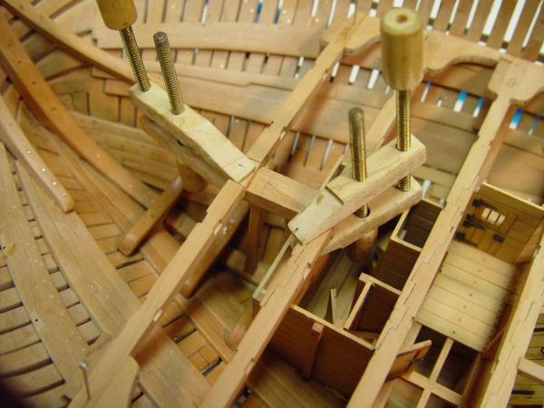
1:60 HMS Naiad 1797 Part 64 – Riding Bitts, Boatswain’s Store, Lower Deck Structure Posted 4/6/11 As with the beams at the stern, the installation of the forward beams had to be preceded by some other work. The boatswain’s stores and the sail room were mentioned previously. In the first picture the long fore and aft partition is being marked out for cutting notches to fit around the beams. The partition is only temporarily positioned for marking. It was then removed and the notch cut on the circular saw. It was then returned to position to mark the next beam – and so on. The next picture shows this partition being glued into place with all the notches having been cut. Putting the base stringers for all the partitions in place first, with the door cutouts, simplifies this final installation. This can be seen in earlier pictures of this area. The stanchions on the pre-fabbed partitions are cut off at the bottom to fit on top of the stringers. The lowest planking is then glued to both the deck and the base stringer with position and alignment already established. It only remains to get and hold them vertical. The next picture shows two of the transverse partitions in place. These were made oversize, detailed, then fit to shape with the beams removed. The boatswain was responsible for the ship’s rigging, so this area would have been crammed with spare rigging items. The forward area was the smaller of two sail rooms, so it has dunnage battens on the floor to allow air to circulate under the spare sails and canvas stored here. The larger sail room is over the magazine in the center of the ship and will not be modeled. Before the area over the forward hold got congested with beams, the riding bits needed to be installed. In the next picture the first of these is being glued into place. These massive timbers were anchored to beams from the depths of the hold to above the upper deck where a cross piece was attached. The bits are 16 inches square at the top. These are the aft pair of two sets of riding bits. They were used to secure the cable when the ship was at anchor. To hold it in position for gluing, the huge timber is clamped to a beam held in place with pins and forced gently against the rear bulkhead of the magazine and the fore platform beam with a tapered piece of wood lodged against a small ledge. “Gently” is the operative word here. I wasn’t gentle enough on the second one. In the next picture both bits are in place and the effect of wedging the second against the ledge too forcefully is apparent. These timbers were then bolted through both the orlop beam and the lower magazine beam and will of course be bolted through the adjacent lower deck beam. There was just enough room to drill holes for these first eight bolts. They are just visible in the above picture. They can be seen more clearly in the next picture. The camera’s critical eye is evident here, showing the marks from the drilling, which I had not seen. This will require some cleanup with a file. With the bitts installed, work could continue on the beams. The next picture shows a mortise being cut into an orlop beam to receive the bottom of a support pillar, which is lying to one side. This is being done with a 1/16 inch mortise chisel. The last picture shows that beam and the one just forward permanently installed with their pillars in place. Hopefully, the rest of the beams and at least most of the lower deck carlings will be installed by the next installment. Cheers, Ed
-
1:60 HMS Naiad 1797 Part 63 – Mizzen Step/Lower Deck Structure Posted 4/5/11 Once all the bolts were installed holding the knees to the lower deck beams, the beams could be installed permanently. Currently all the beams aft of midship have been installed. The forward beams are waiting for installation of the partitions for the boatswain’s store and sail room. These are being fabricated. In the first picture the stairs leading down to the aft platform have been installed. The slots for the treads were cut on the milling machine with a slotting blade the thickness of the treads. Enough of these were cut to finish the model – hopefully, unless different angles are needed. The next picture shows this from a different viewpoint. This picture shows why the hatch covers to the spirit room had to be redone. The stairs, the adjacent beams and the carlings were installed together before moving on the the rest of the beams aft. The mizzen step was also installed along with its supporting beams. Doing all this together is easier than installing these things later. The next picture shows the lower half of the mizzen step being installed. This piece is quite a large timber. It is “let up” under the beam and is long enough to reach the other side of the beams. It has a large pillar support it in its center, which cannot quite be seen in this photo. The mizzen step itself rests on this and is let down on the beams in scores about 2” deep in the centers of the beams. The next picture shows this in place. The pillar under the step can be seen in this picture right up against the aft wall of the magazine. In the next picture shows the bolts, which go through both step timbers and the beams. This picture also shows the remaining beams aft being installed. In the next picture work is progressing on the installation of carlings aft of midship. This step goes quite quickly, since all the seats were cut before the beams were installed. The last picture shows the carlings in the partitioned area. The partitions needed to be slotted here to fit the carlings. This was done with a sharp chisel. Some other tasks have been going in parallel with the above work. These include installing the iron nails in the ribbands, building the bulkheads for the boatswain’s stores and fabricating copper braces/gudgeons for the rudder. This work will be covered in later posts. Ed
-
Thanks, Guys. I'm looking forward to getting this reposting done, so I can post the final stages of the build. I just finished gluing on what I think are the last wood parts - except for the gun doors. But first a couple more reposts.
-
HMS Victory by EdT - FINISHED - 1:96 - POB
EdT replied to EdT's topic in - Build logs for subjects built 1751 - 1800
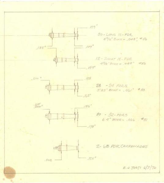
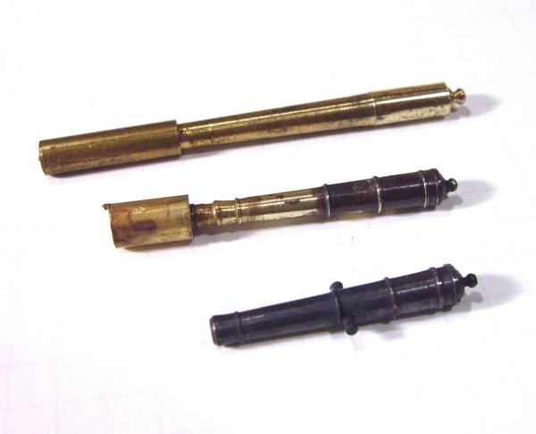
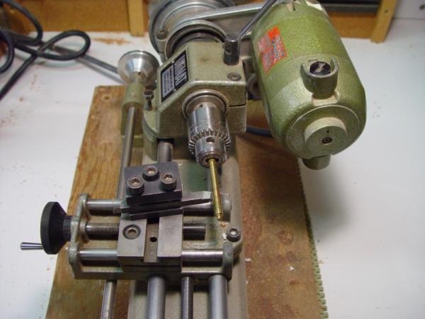
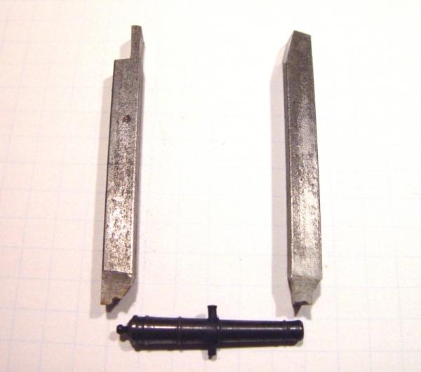
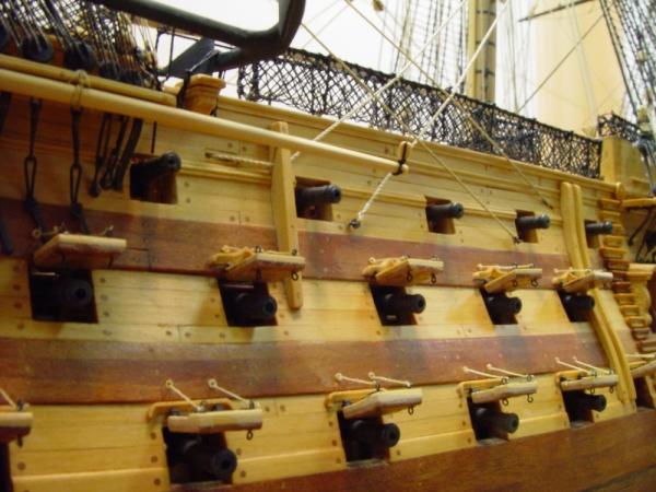
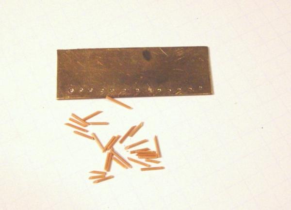
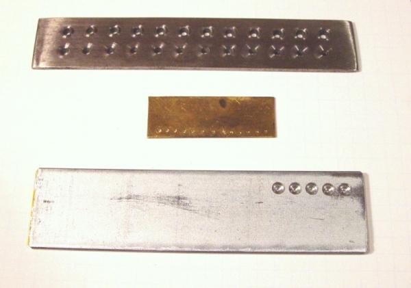
HMS Victory 1:96 Scratchbuild Project Part 5 – Gun Barrels and Topside Planking In this part I will focus on the modeling of the gun barrels. These needed to be made for the lower and middle decks so the carriages could be correctly positioned before installing the beams and planking for the decks above, after which, they would be inaccessible. I will also start in on the topside exterior planking in this part. The Gun Barrels One of the extra middle deck 24 pounder barrels, blackened after machining. All of the 102 gun barrels were individually turned in brass on a miniature machine lathe, a Unimat SL, which I was fortunate to purchase used, in mint condition, at a very good price in the late 70’s. I spent as much again on accessory parts, including the circular saw attachment and the indexing head among others. It has been durable, easy to use and capable of a number of precision operations – turning, drilling, milling, circular sawing, precision grinding, etc. The Unimat went out of production some years ago, so I was glad to have bought the accessories when they were available. Later they would become indispensable for a number of operations, which I will describe in their proper place. Unimat tools and accessories are still traded on eBay. Later, I purchased the Preac circular saw and a Sherline milling machine. These would make the aging Unimat less essential. Both are excellent tools. I still use the Unimat regularly, however, for all manner of tasks. I wanted the guns to have a recognizable metallic sheen for aesthetic purposes. The clean metallic finish highlights the detail on the guns very well as opposed to paint. This effect was obtained with a blackening agent, which was used for this purpose and for virtually all the brass “ironwork” on the ship, from the anchors to the small hooks attaching the futtock shrouds to their deadeye chains. The drawing below was done on a piece of file folder, knowing it would have to put up with a lot of wear and tear on the bench. On this, a dimensioned drawing of each type of gun was made at scale size. Also noted are the drill sizes for the different bores. It was very convenient having all the necessary information on one card and all machining was done from this drawing. The guns were turned from brass rod. Although machined individually, uniformity and efficiency were achieved by doing one operation at a time on all the barrels of a given size. To do this efficiently, work pieces had to be in and out of the machine constantly. To facilitate this, the pieces were held on the muzzle end only in a Jacobs chuck, making change out fast and easy. This meant barrels would be drilled last without the benefit of centering in the lathe, but that disadvantage was accepted. Below are a pair of rejects of the process from my scrap bin that show the way these were chucked – on the stubs at the left. First the outer diameter of the ring at the breech was turned. Then the pommel and breech end were cut in one operation with a special cutter (see below). Then the headstock of the lathe was rotated slightly to allow the taper of the barrel to be turned between the breech ring and the ring behind the muzzle. The raised rings were then located and the correct barrel diameter between them was turned. . The setup for this tapered turning is shown in the picture below. Keep in mind that each of these steps was done on all the similar barrels before moving on to the next step. The Unimat is (was?) a very versatile machine. Mine is permanently mounted on a plywood base. Under the base a piece of foam carpet mat can be seen. This holds small machines like this in position while permitting easy movement out of the way when not in use or to different orientations on the bench. The white bench top is laminate coated particle board, bright, durable and easy to keep clean. After all the tapered machining was done, the headstock was returned to normal for the finishing of the muzzle end. Special cutters were ground to facilitate and standardize the machining of the muzzle flare and the pommel at the breech end. The picture below shows these cutters. The ¼” square Unimat bits were ground to the shapes of the muzzle and breech. When all of this machining was done, the barrels were polished in the machine with crocus cloth and fine steel wool. Then the barrels were parted off the stubs and the muzzle ends filed smooth. Drilling the bores was then done very carefully to assure centering. They were drilled to their correct size held vertically in the Unimat vise with the machine set up as a drill press. Only a few barrels had any visible bore misalignment. The worst of these were rejected. Fortunately several extras were made for each type. The last step before blackening was the drilling for the trunnions. The fact that these are below the bore centerline adds a slight complication. A jig was made to hold the barrel under the drill press so that the trunnion bore would be offset below the centerline. The bore location was given a center punch mark to help avoid the drill slipping off the curved barrel. After drilling, the trunnions were slipped in and held in place by a slight hammer tap on the bottom of the barrel. This avoided soldering with its potential blackening issues. Finally, the blackening. It is best to blacken right after machining. Getting good results from blackening solutions may be a science, but it feels more like an art form. The problems experienced included: spotty blackening, blackening that rubs off, sooty like buildup, and flaking off, etc. The ways I battled these problems included, assuring very clean polished brass before dipping, degreasing with acetone, thinning the solution with water to slow the process, swabbing parts with Q-tips while immersed, allowing to dry before buffing, frequent changes of solution, multiple partial dips, plus others I am sure. I wish I could say that any one of these was consistently successful. Blackening silver soldered joints or overheated small parts was often troublesome and in some cases parts had to be re-dipped because of wear, after which some would not blacken at all and a few (very few) had to be painted, or touched up. This was not required on any of the guns and after blackening they were buffed up with a soft rag and put away for future installation. The three tiers of guns below the waist.on the port side. Topside Planking Overview The workmanship on the topside planking makes or breaks an unpainted hull model. I wanted crisp lines, sharp edges, tight joints and cleanly cut moldings and rails. Most of all I wanted to highlight the beautiful sweeping curve of the ship’s sheer line. Note I do not mean the line of the gun ports, which follows the line of the decks, which is a much flatter curve than the line of the sheer. The “Nelson Stripes” painted between the gun ports may have suited his fancy, but, unlike the painting of earlier years, it did nothing for the beauty of the ship. This treatment gave these ships an awkward flatiron look, which I did not want. What I did want was to accentuate the gracefully curves lines of the sheer. To do this I decided to plank the three wales in the darker cherry and the rest of the planking and the rails in the pale yellow European Boxwood. Both are hard, flexible woods, capable of taking a fine polish without finish. In the end, I gave them a rub of very dilute Tung oil wiped dry, then a thin solution beeswax dissolved in turpentine, buffed. This was done mainly to prevent staining during the later stages of the work. This even allowed CA drips to be flaked off when they occurred. Of course, no further gluing to the surface was possible after this treatment. Tree Nails Before describing the planking process itself, I need to discuss treenails (or trennals, or trunnels, etc). These were used extensively throughout the model, both for appearance and for added strength. Glue alone was only used where treenails or others types of fastener was not practical, usually because of scale. For example, the wriggles above the gun ports in the above picture are glued only. Because of the 1:96 scale, proportionately sized fastenings are not practical, so there was a compromise of fewer and larger tree nails vs. the original. These were made from Boxwood, although some were made from Bamboo. The round diameter of the treenail was made with a drawplate, a thin metal plate with an array of holes of decreasing size down to the desired nail diameter. In practice, getting a diameter below .030” (2 ¾” at 1:96) was hit or miss, so .030 became the standard minimum size. Larger diameters were used in structural applications, for example on beams. Below is a picture of some tree nails and the simple drawplate I made from hard brass sheet, which was used to make all the nails used on the ship. The almost worn out brass drawplate with some .030” tree nails. The usable holes in this plate, the first 7 from the left, range in size from .039” down to .031”, that is number 61 to 68 drill size. The process of making these nails was as follows: Strips of boxwood maybe 12” long were sized down to 1/32” square (.03125”) or slightly larger. One end the strip was tapered so when pushed into the largest hole, enough emerged to grab with a pair of pliers. The strip was then pulled through each successively smaller hole with even pressure. Final diameters of 030” were consistently achievable. The strips were then cut with a sharp chisel to length, first on a slant then square, then on a slant again, etc. to yield small nails with a square top and a pointed bottom. Thousands of these were made. Above is a picture of three drawplates. The top plate is a purchased item (Cost on sale $25). Holes range from 1/16” down to .037” (No. 63 drill). This is made of steel, and is perhaps hardened. The holes are countersunk on the “pull out” side. You want only a small amount of metal to pull through. The cutting should be done on the back face of the hole. You do not want to squeeze the wood into the hole, but rather scrape off its surface on the way in. The middle one is my brass plate (Cost about $0) with holes from .039” down to the usable .030” and several sizes below, at which strips begin to break. The bottom plate is one I have recently made from 1/8” thick steel, which I intend to use on my new project. The middle plate will get a well-deserved retirement. The new plate begins where the upper plate leaves off and then goes down to a final .030” hole size. I will briefly describe how to make this plate since it seems to work very well, is easy to make, could easily be made to handle the full range up to 1/16”, and, very importantly, is inexpensive. First I bought a 1/8” by 1 ¼” by 36” (the only length they had) strip of galvanized steel for $5. Galvanizing isn’t necessary. The plate should be wide enough to leave some room below the holes when clamped in your vice. After cutting the plate to length, countersink holes were drilled using a 1/8” drill, to just above the bottom of the plate, that is, almost but not quite all the way through. I would guess maybe 1/64” of metal was left. Then using small drills, smaller holes were drilled in the center of the larger holes, from the same side. Burrs were filed off both sides to complete the drawplate. I do not intend to harden the plate based on the longevity I got from the much softer brass plate, but if you want your great grand children to use it, you might wish to harden it. I also learned that Brynes Tools sells what appears to be a very nice drawplate with holes down to .016” for $25. In the next episode, I will discuss how matching “anchor stock” and “top and butt” planks for the wales were made, how different rail moldings were made, and how planks were bent, clamped and fastened to the hull. Cheers, Ed Tosti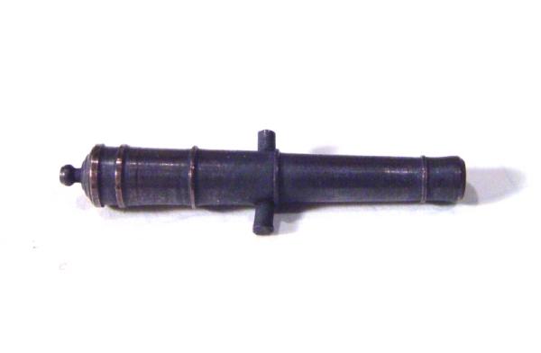
-
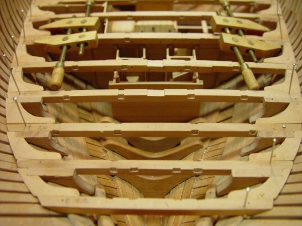
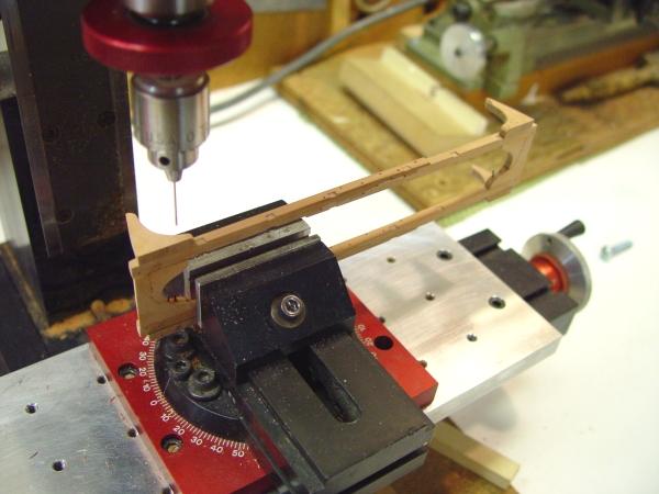
1:60 HMS Naiad 1797 Part 62 – Lower Deck Beams Continued Posted 3/29/11 Having glued all the knees to their respective beams, the next step was to install the bolting. The knees are bolted to the beams with iron bolts in the fore and aft direction. These are simulated with 30 lb. test black monofilament fishing leader. The bolts go through both knees and the beam – three at each end. The picture below shows the setup for drilling these to help get the drill exit points in the right place. In this picture the two beams at midship have been assembled so their knees can all be bolted. These beams have a pair of opposed lodging knees between them so they needed to be assembled for this. In the next picture bolts have been installed in most of the beams and they are waiting to have those trimmed back flush and sanded smooth. After the holes were drilled, a length of monofilament was cut from the spool and the end dipped in medium viscosity CA. It was then inserted in one end of the hole, removed, re-dipped in the glue and pushed all the way through the hole from the other end, then clipped off. This assured that the bolt would be tightly held at both ends of the hole, adding strength to the joint, which is inherently weak in the case of the lodging knees because they are glued on end grain. After drying of the CA the bolts were sliced off with a knife and sanded flush to the wood. The next picture shows some of the bolting on the knees after the beams were put back in their positions. This picture also shows the first of the pillars to be fitted under the beams at the centerline. These are mortised into the beams of both decks. They need to be carefully measured to make sure they do not disturb the fair line of the beams fore and aft and cause waviness in the decking. Below is a closer view of these pillars, which have their corners chamfered off in the middle of their length. The next picture shows a few more of these further aft. Between the platforms the pillars extend all the way down to the keelson. The next picture shows some of the beams over the central platform permanently installed. With all the gluing finished on this section of the orlop deck , some of it has now been given a coat of wax finish. That is the reason for the slightly darker cast to part of it. These first beams were a test for my plan to drill through the knees from outside the hull to install full through-bolts. This seems to work all right for the lodging knees by using the drill guide I described earlier, but I found that controlling the drill exit point on the hanging knees was just too unpredictable to give good appearance. Also, it is virtually impossible to finish the hanging knee bolts flush with the beams in place. While this second problem could be overcome, I have decided to compromise on this bolting. The knees will still be bolted from the outside, but I will not drill all the way through them. Bolts on the inside of the knees will all be pre-installed and finished off. This will give the appearance I want, but will not be 100% authentic. C’est la vie. The next picture shows a pile of beams with copper bolts installed on the knees waiting to be filed off flush. I’m actually waiting for delivery of some 220 grit sleeves for my new spindle sander – a birthday gift – before going at this. The nails at the ends of the beam scarfs can also be seen in this picture. These were added to all the made beams. I knew I had read about these somewhere but couldn’t remember the reference, so until I found it buried in Steel, I deferred installing them. These smaller iron bolts (or nails) were made using smaller monofilament. Just in case someone is wondering why the mix of copper and iron, in the absence of any definitive data, I am using copper for all bolts through the hull from roughly the waterline down and iron for everything that is not normally immersed in saltwater. The rationale is that iron is stronger and was cheaper. Copper was resistant to salt water but somewhat weaker and much more expensive. Seems a reasonable approach. So, the next step will be to trim off the excess copper bolting, finish sand the beams, and then proceed to get them installed. The partitions for the boatswain still need to be done as can be seen in the last picture. Ed
-
1:60 HMS Naiad 1797 Part 61 – Lower Deck Knees 2 Posted 3/27/11 In the last part some work had been done on the partitions on the aft platform. This work is now complete. Hardware has been added to the doors to the light room and the aft magazine and that whole assembly was fixed permanently in place. To the right of the light room door is the Dutch style door to the stewards room. The steward reported to the purser and was responsible for distribution of stores, hence the Dutch door. There is also a small sliding door leading to the bread room from this room. The steward slept in this room. To the right is the slops room then the marines clothing room. Slops was the term given to seamen’s clothing and gear that were issued to new arrivals on the ship who may not have had a chance to outfit themselves before being picked up by the press gang. Deductions from wages were made accordingly. Also in this picture the hatch to the spirit room has been converted to a “double-flap.” A ladder way to this deck will descend above this hatch. The next picture shows this area with the overhead beams temporarily in place. Most of the effort in the past two days involved the hanging knees and the progress of their installation is shown in the next several pictures. The next picture shows the knees installed on beams over the central orlop. The hanging knees at this stage are glued to their respective beams only. All the knees still need to be trimmed down flush with the beams. This view from astern shows the hanging knees on the last several beams. The slots let down in the tops of two of these beams are for the mizzen step. Hanging knees on the beam forward of that are clamped for gluing. In the next picture the very last hanging knee has been glued and clamped. The picture below shows the arrangement of knees on the beam arm assembly attached the beam aft of the main hatch. The knees on this assembly have been sanded down flush with the beam. The double lodging knee in the upper left of this picture is the point at which the lodging knees shift position and orientation. It was important to have a large angle between the two faces of these knees for strength. Here at midship they are roughly 90 degrees, but with the change in orientation the angle of these will increase going fore and aft, which is the reason for the shift. Without this shift the angles at one end would be very acute and strong knees could not be made from wood for this situation. Of course, with the change, the hanging knees also change position on the beams. They are on the forward side forward of this point and on the aft side aft. The next picture shows the deck structure with all the knees installed. All this structure is still removable. The next step will be to remove each beam, trim down the knees flush with the top, get everything sanded and install the fore and aft bolts through both knees and the beam. The pillars under each beam can then be fitted and the beams installed permanently. There is still some partition work to be done on the orlop. The picture below shows the area of the fore platform, laid out for the boatswain’s store and the sailroom forward of that. There will be no partitions installed on the starboard side – only structure. Ed