EdT
-
Posts
2,214 -
Joined
-
Last visited
Content Type
Profiles
Forums
Gallery
Events
Everything posted by EdT
-
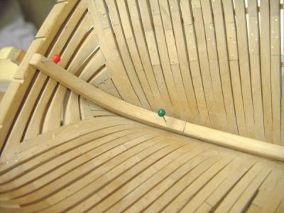
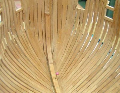
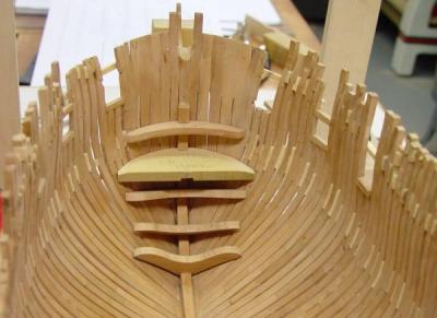
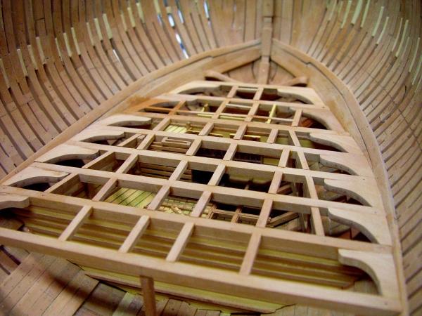
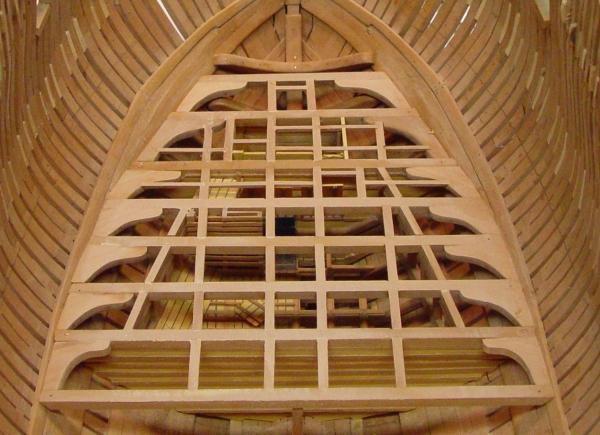
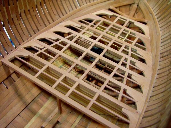
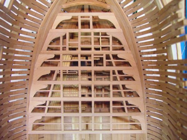
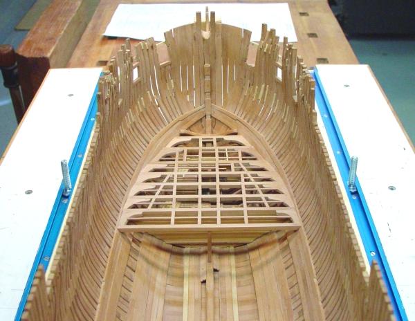
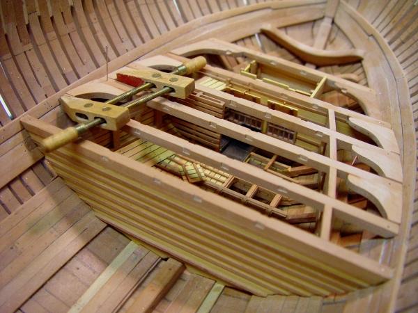
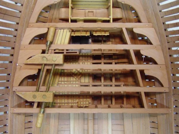
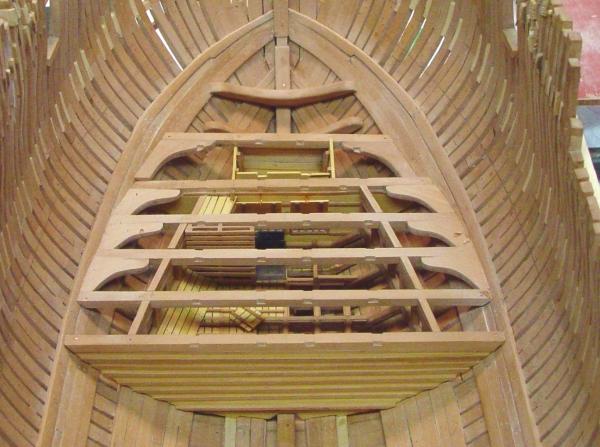
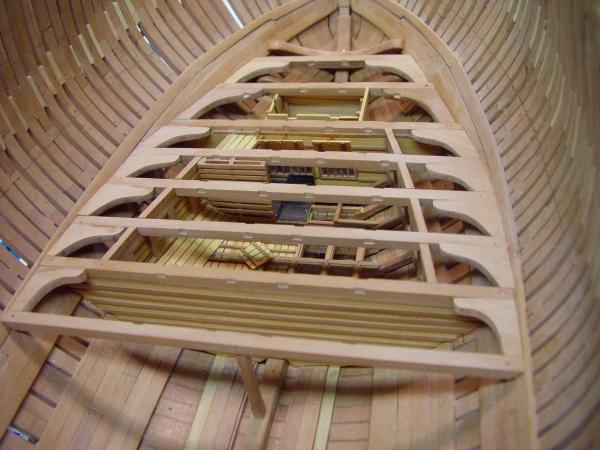
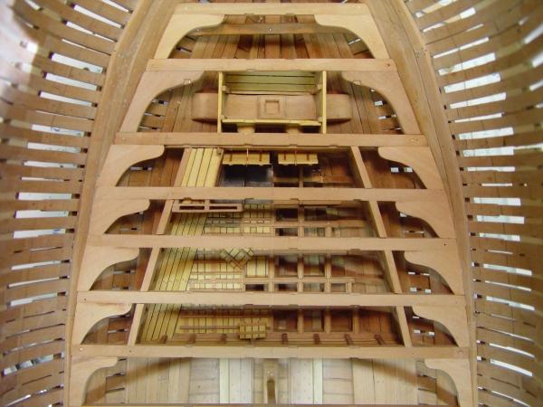
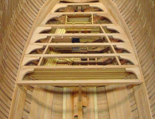
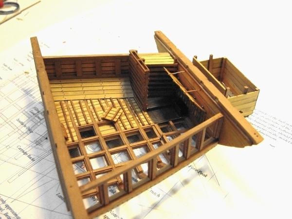
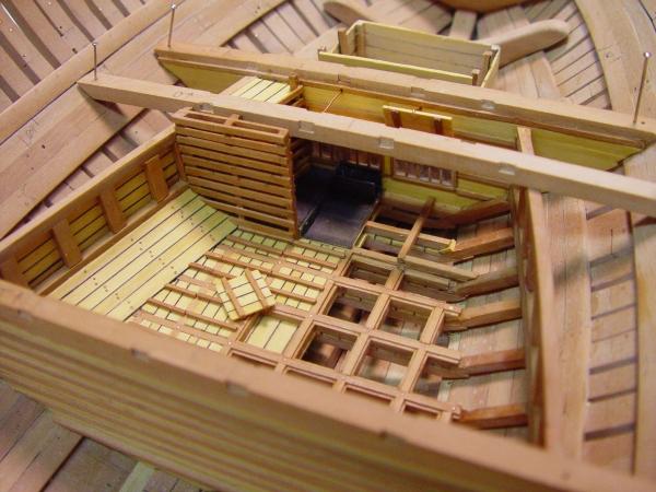
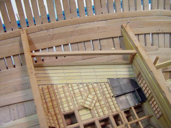
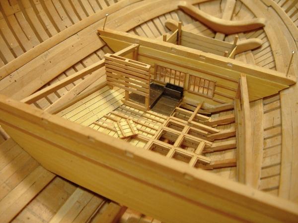
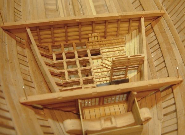
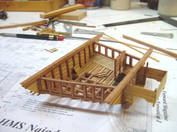
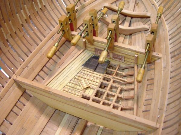
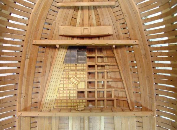
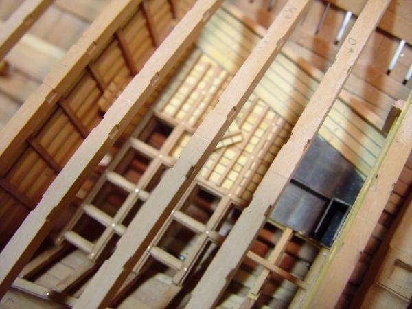
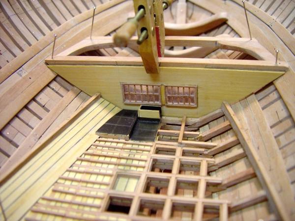
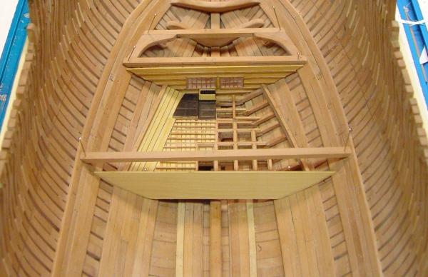
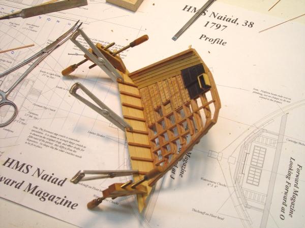
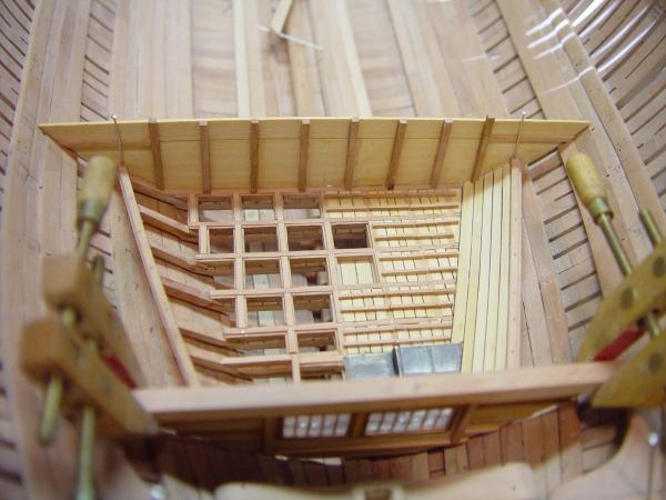
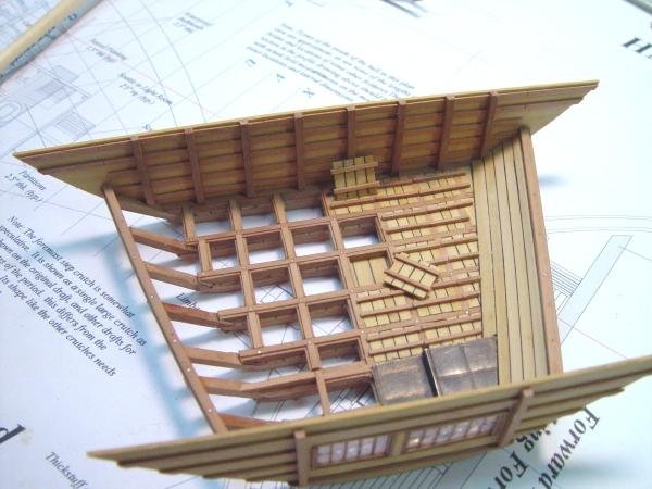
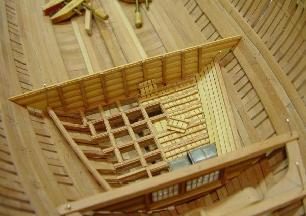
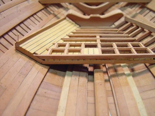
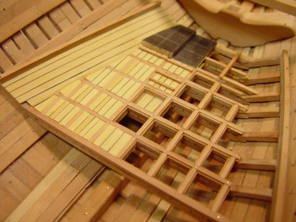
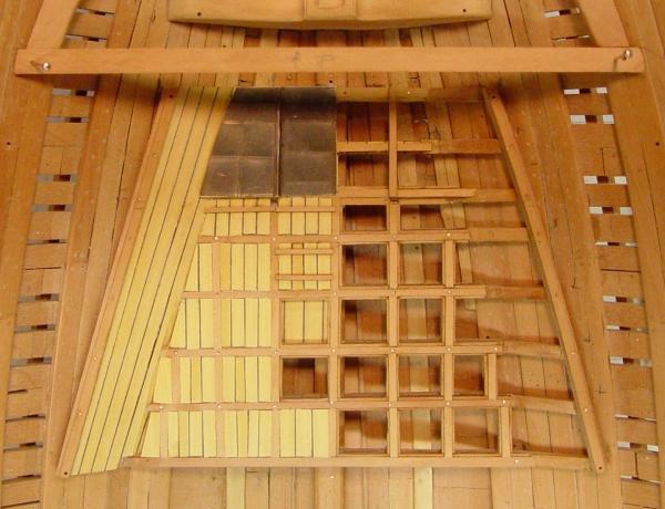
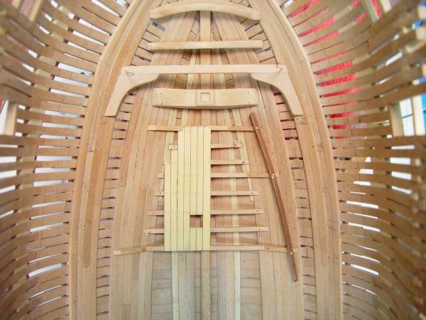
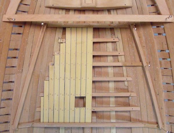
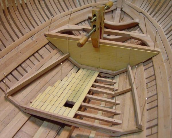
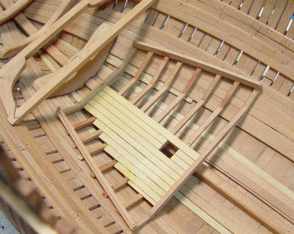
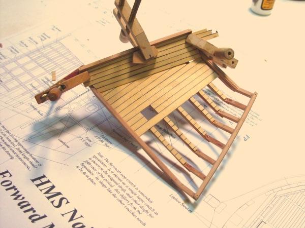
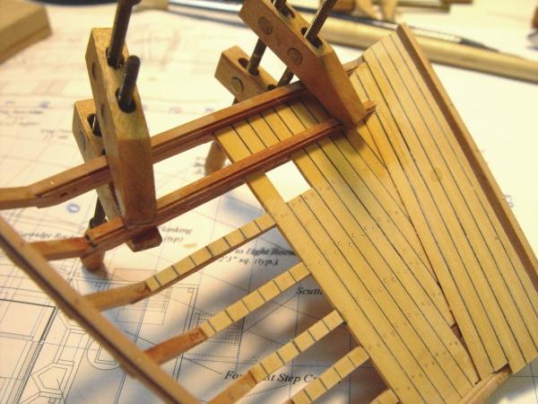
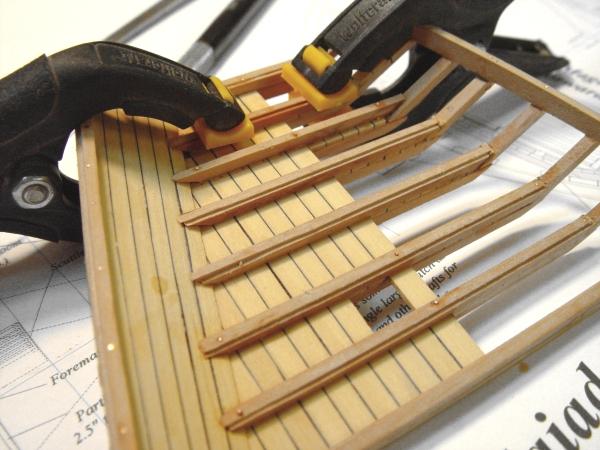
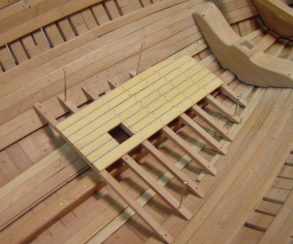
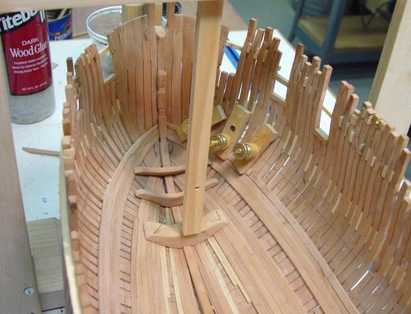
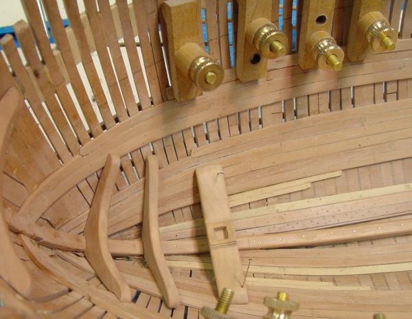
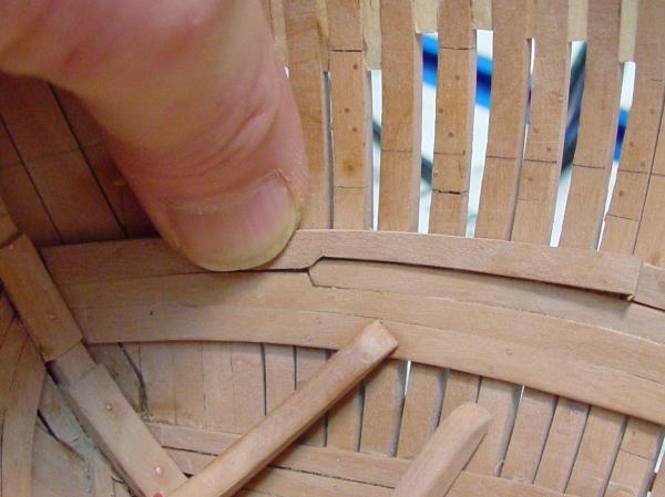
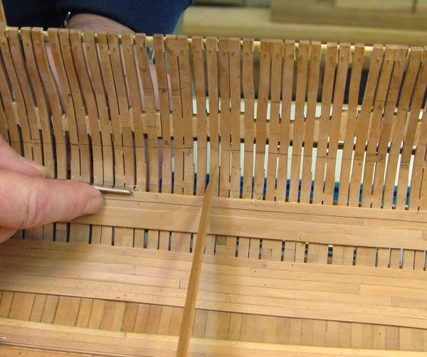
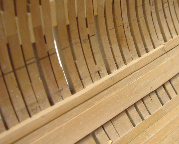
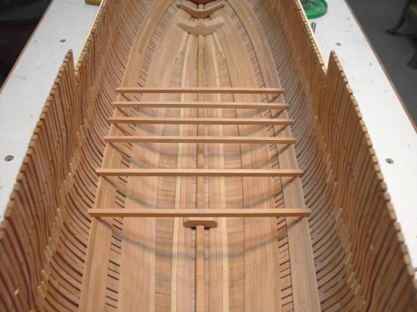
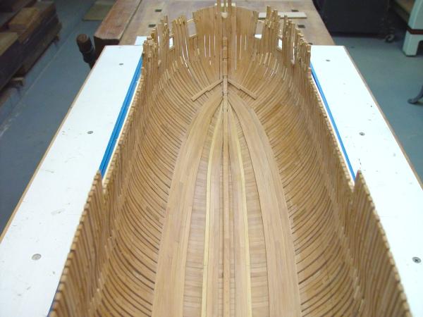
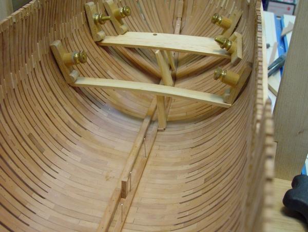
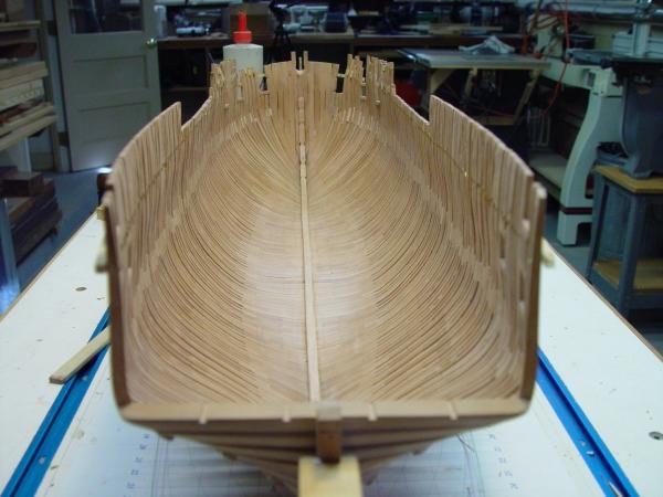
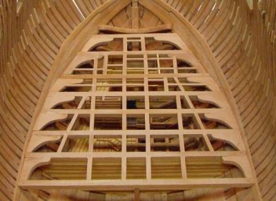
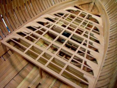
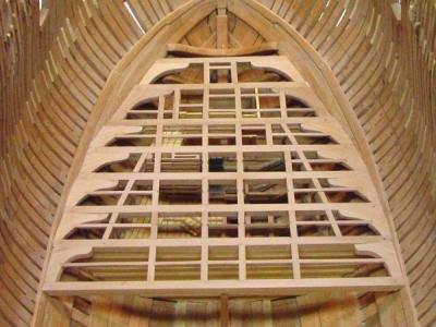
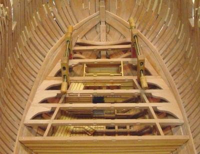
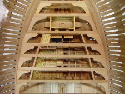
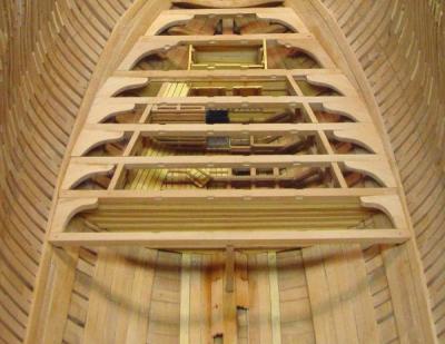
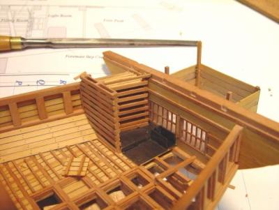
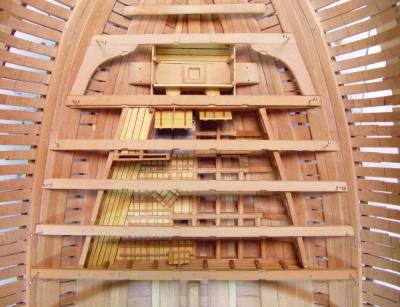
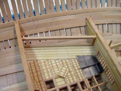
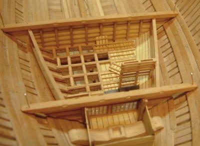
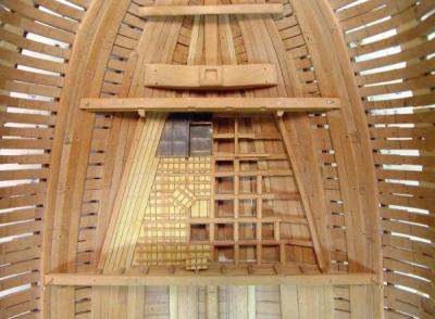
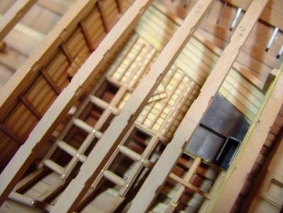
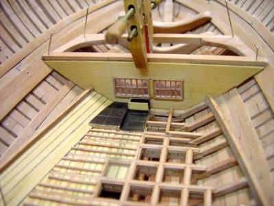
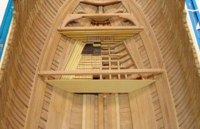
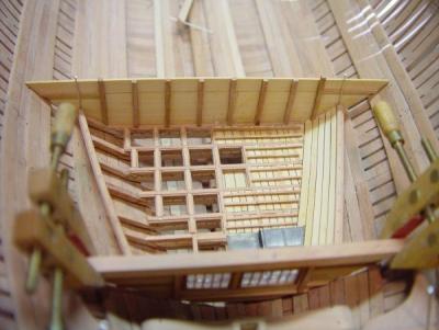
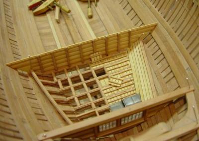
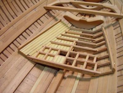
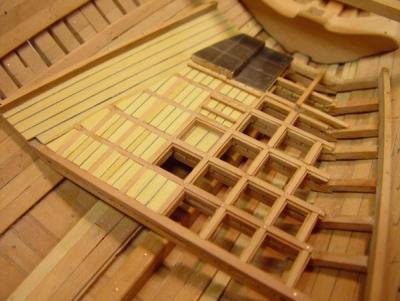
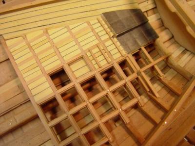
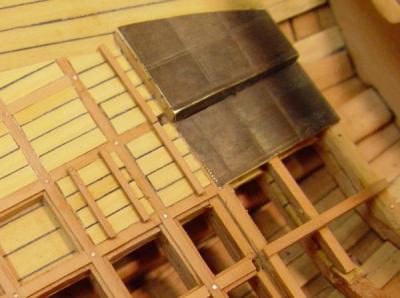
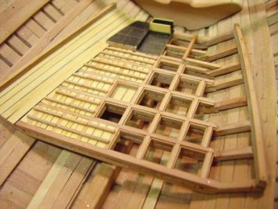
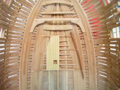
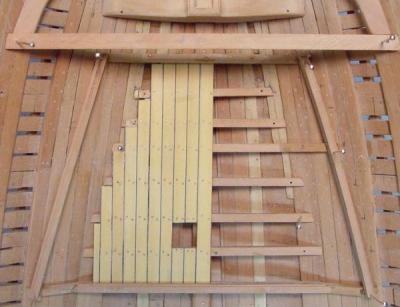
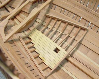
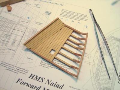
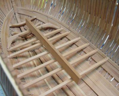
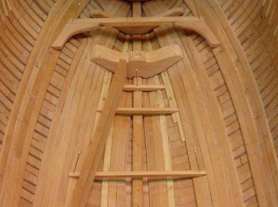
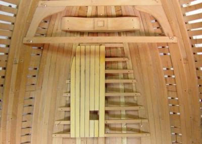
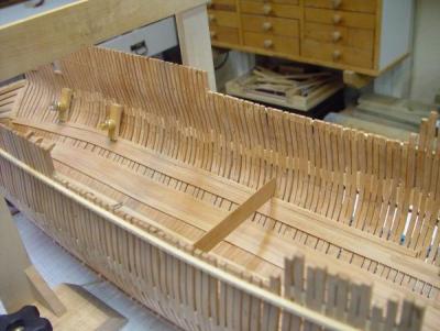
1:60 HMS Naiad 1797 Part 41 – Fore Platform Framing Posted 1/23/11 In this segment the framing of the fore platform, specifically the installation of carlings and ledges, was done. The picture below shows the platform framing with all the carlings installed and a few of the ledges at the forward end. The dark area is due to dampness from washing off the glue in that area. The carling mortises were roughed out on the beams before they were installed. This was covered in part 37. By keeping them slightly undersized any misalignment resulting from the final beam positioning could be adjusted by paring the sides of the mortises in place when the carlings were fit. This worked pretty well. In the above picture the top of the framing still needs to be sanded flush. In the next picture the first pass of this has been done using 220 grit paper with a sanding block. This sanding will be completed after the ledges are installed. There are three scuttles framed in this picture one forward of the foremast leading down to the forepeak, one to the port side of the mast leading to the light room, and one above the starboard side of the filling room which gave entry to the magazine. I am still doing some research on these. I believe they may have been framed with carling sized timbers instead of the ledges shown here, so the three in question may be removed and replaced. If the coamings for these are to rest right on the beams, a wider member is probably needed. All the mortises for the ledges were cut in place, so they would line up properly. In the next picture the installation of ledges is complete. The ledges directly over the magazine have been left out to improve the ability to see this area. The mortises for these have been cut, however. The next picture is another view of the finished platform framing after sanding and polishing. And below is another view from directly overhead. The next picture shows the whole forward end of the inside of the hull. There are a number of directions to go from here, perhaps planking of the platform or starting on the central orlop deck will be next. We’ll see. Ed Copyright 2011 Edward J Tosti

-
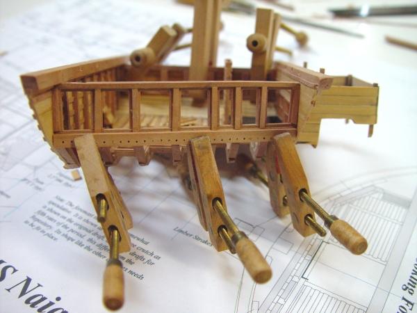
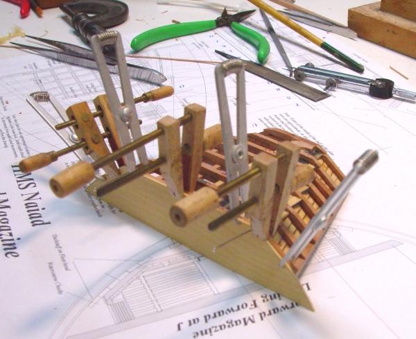
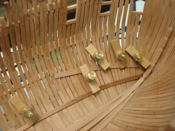
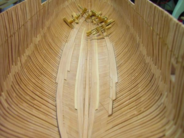
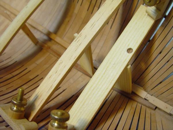
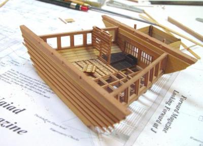
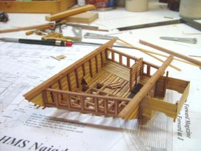
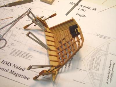
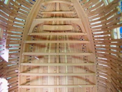
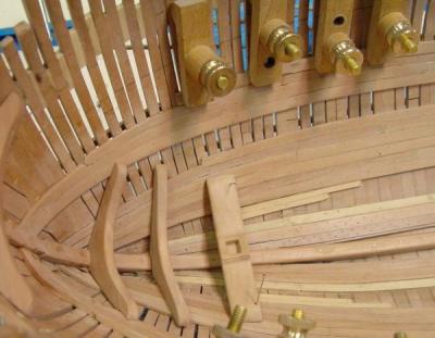
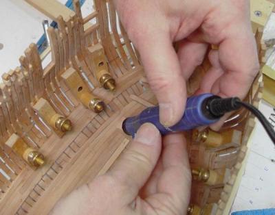
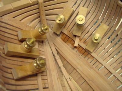
1:60 HMS Naiad 1797 Part 40 – Fore Platform Beams Posted MSW 1/18/11 By this time the forward magazine assembly had been permanently fastened into place and the filling pieces on top of the side panel lintels between the beams installed. In the picture below, work has begun to attach lodging knees to their respective beams. Except for the two beams attached previously to the magazine, all the other beams are still loose in this picture. The curve of the lodging knees was cut on the band saw in a 3 inch thick piece of stock then finished with rasps and sandpaper. The individual knees at a thickness of 7.5” were then sliced off this. They were then sized and shaped to fit their respective beams. The knes are 3’11” long along the beam itself. I will go into this method of making the knees in a later segment. I am still working on this new process. In the above picture and the one below, the knee is being glued to its beam, flush with the top of the beam. Although all but one of these kneed beams are still loose and a bit out of alignment, it can be seen that getting these to follow a fair line where they mate with the side is a bit of an issue. This is due mainly to the extreme angle where the beams rest on the planking, the differences in planking thickness and the way the line of the beam tops diverts downward from the lines of the planks. Once the knees are glued to the beam, they are removed, taken to the milling machine, and drilled for the bolts that go through the beam and also those that go through the frames. Getting bolt holes to be horizontal and go through the center of the knee thickness, drilled from the outside is a process that needs development. Due to the small space between beams, drilling from the inside is not very practical. Until I get a process for this, these early orlop beam knees will have dummy bolts on the outside. After the bolts were put in the beam/knee assemblies could be secured into place. The following picture shows this in progress. The forward most beam is still loose. A beam forward of that one, which seems to have been omitted from the Naiad draft has to be made, fitted and have its carling mortises matched up before this beam can be secured. In the next picture this has been done and the beam over the forward light room partition is being glued in. After gluing, all these beams were bolted into the ceiling planking with copper bolts. In this next picture all but perhaps the most forward beam have been secured. The aftermost beam of the platform has a pillar under it supporting its center off the keelson. This has a square mortise and tenon in both the top and bottom. The next picture shows the new forward most beam with the mortises cut for its carlings. These two carlings will frame the scuttle to the forepeak below. The last picture from aboveshows all the beams in place. There is still a bit of leveling of all these pieces to be done and this will help with the fairness of the curve along the outer edges. The last picture is another view of this, in which a number of limber boards have been installed starting at the magazine bulkhead. These are beveled to fit against the keelson and also have half round holes in each end so they can be pryed out to clean out the limber channel. The next step will be to install the carlings and ledges in the platform framing. Ed Copyright 2013 Edward J Tosti


-
HMS Victory by EdT - FINISHED - 1:96 - POB
EdT replied to EdT's topic in - Build logs for subjects built 1751 - 1800
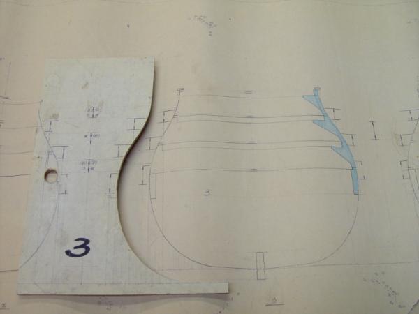
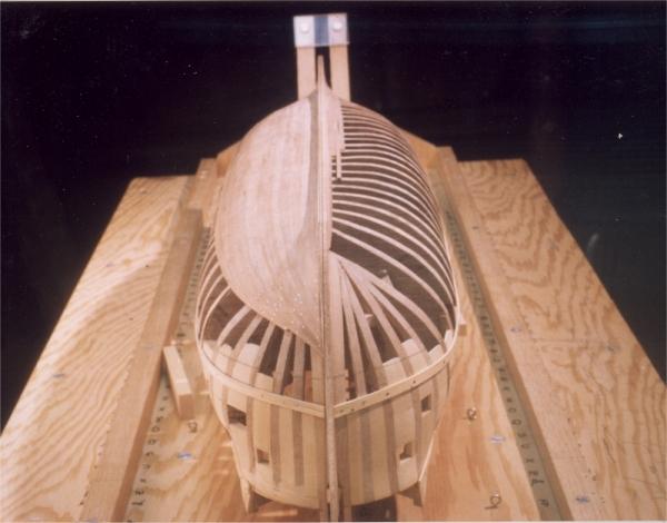
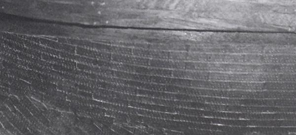
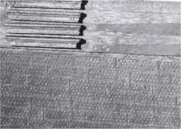
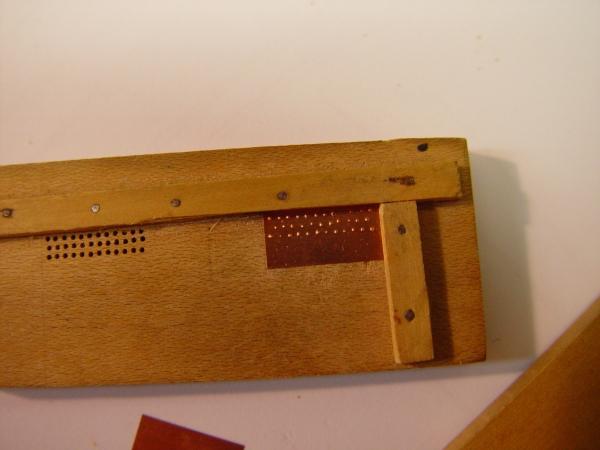
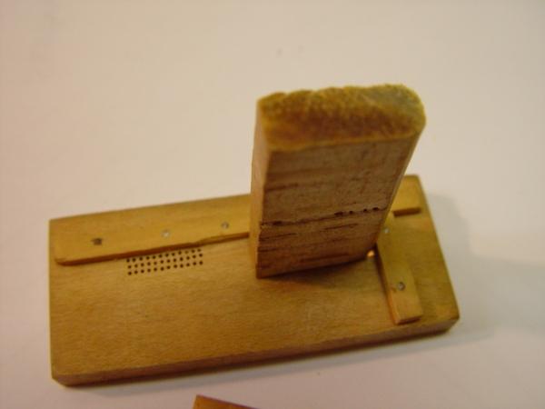
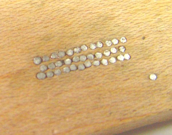
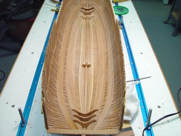
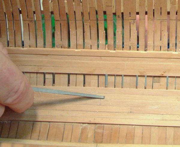
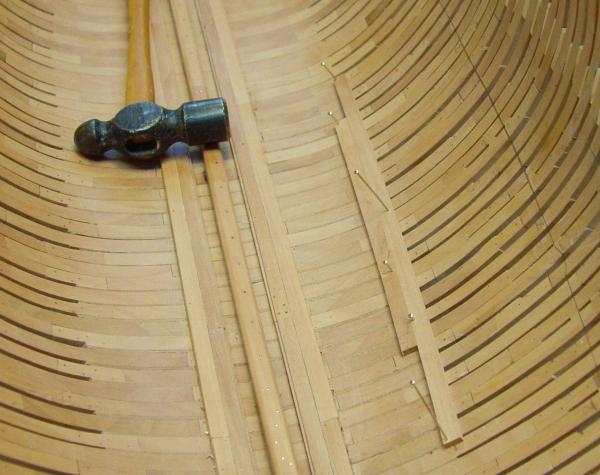
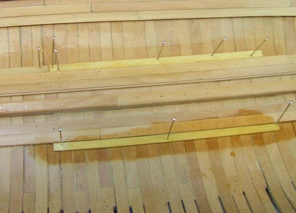
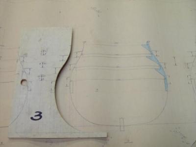
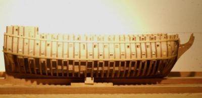
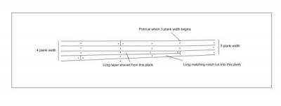
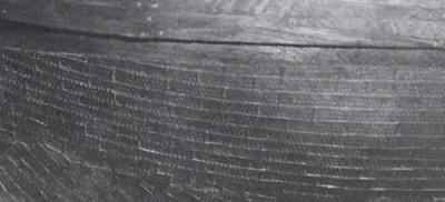
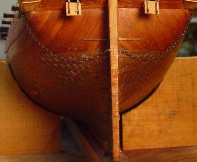
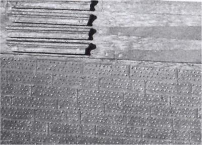
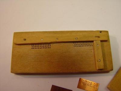
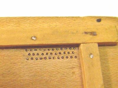
HMS Victory 1:96 Scratchbuild Part 3 – Framing, Hull Planking and Coppering Keel Assembly The first item to be made was the keel/sternpost/stem/head assembly. All were made from maple. If I were doing this again at least the head assembly would be cherry to match the other visible wood. The keel section is not like the original. It is deeper above the top of keel line to support the bulkhead/frame assemblies. The rabbet on the keel was cut using a small shaped scaper as shown in the following sketch. I used a lot of these little scrapers for various tasks. Mine were made from 1/16” stainless steel only because I had that and it files easily. Other materials will work as well. If they are hardened steel, heat them until red, then allow to cool. File the shape, then (optionally) heat to red again and quench to harden. For the keel rabbet the scraper was simply drawn along the keel with the side marked “bottom of keel” held to the bottom until the full depth was reached and the cut was stopped by the side rounded edge. At the ends and along the sternpost and stem this device could not be used so the rabbet was cut with a small chisel. The assembled keel, sternpost, stem, head assembly was then set up on the board and fixed into a vertical position on the centerline. I am sorry but I have no pictures of this. Frames Unlike Longridge, I intended to model the ship with all ports open. This required some modeling of the lower decks and a change to the way Longridge cut his frames. I made my frames to allow access to the lower decks by assembling them with removable deck beams. A drawing of this is shown below with its alignment guage. The area below the lower gundeck was a solid 3/16” thick bulkhead. Topside frames with knees to support the beams, shown in blue on the drawing, were cut out in one piece and fitted to each side on the pattern sheet along with the beams. Side frames were glued and pegged, beams were pinned only, from the outside. Bulkheads and frames were cut out of 3/16” lauan, a medium soft wood that would accept pins and copper nails easily. Beams were cherry, rounded up to the correct level at their centers. This was done taking a wide, say 2” wide by 3/16” thick cherry, cutting it to the length of the midship frame deck beam, marking the centerline, then steaming it and clamping it over a form cut to the shape of the round up from a 2X4. Actually the round up was exaggerated slightly on the form to allow for some spring back when the beam stock dried. This can be judged by trial and error. When dry, the beams were ripped to their correct width, cut to length maintaining the correct centerline, fit into their frames and pinned through locating holes drilled through the frame. Each frame was then set up on the keel and held in place by gluing to blocks the thickness of the space between frames. The picture below, taken later, shows these frames. Also visible in this picture is the piano wire running along the centerline, which was used to square up the frames when gluing them to the blocks between the lower bulkheads. This work all went quite rapidly. A few cant frames were added to round out the bow framing. These were patterned by rotating forward sectional profiles to the true view angle. This method was described in the full length drafting section on MSB. These were then cut out and glued to the stem/keel and also to an internal horizontal rounded support which is not visible. None of this framing is at all historically accurate except for the outer profiles. Also visible in the above picture are white pine filler pieces glued between all of the frames. These were installed for three reasons. First I needed thickness to be able to securely fasten external hull fittings and to simulate the planked interior, which though not visible, was desirable. Second, since I wanted the external planking to be cut to realistic lengths, especially the anchor stock planking of the wales, I needed something between frames on which to fasten that planking. And finally, I needed filler between frames to accurately locate gun ports. The pine provided this. Later the ports were lined with thin cherry before planking. In the picture the hull has also been faired to final shape and two battens have been pinned on in the curve of the sheer line at the bottom of the main wale and the top of the upper wale. These would provide guides for the planking. Lower Body Planking The picture below shows the lower body planking in progress. No filler pieces were needed here because planking, which would later be covered with copper, was put on in long lengths. All the lower body planking was cherry, just less than 1/16” thick and 1/8” inch wide. Planking was fastened using Titebond wood glue and small copper nails on each frame. Titebond, an aliphatic resin, water based wood glue, was used for all wood-to-wood joints throughout the project. It produces a bond at least as strong as the wood itself, has sufficient work time to allow parts to be precisely positioned, holds parts together in an hour or so and completely sets in several hours. Excess can be wiped or washed away with water, or scraped off later. Clamping or pinning is needed at least until the preliminary set. Copper nails were made by cutting a long piece, say 24”, of 20 gauge wire, clamping one end in a vice and pulling the other end until the wire broke, thus stress hardening the wire so it could be used for nails. The wire was then cut at ¼” intervals with one end snipped off square and the other at an angle. Pilot holes through the plank were drilled for these nails at each frame. The size of the hole was made slightly smaller than the drawn copper. After applying glue and positioning, the copper nails were simply hammered into the soft framing, so no clamping was needed. The lower body planking began at the keel and worked upwards to the lower line of the main wale in such a way that the last planks leading up to this line were parallel to it along their whole length. Of course, all the planking had to be applied in fair lines, that is, smoothly curved lines. This raises one issue, which deserves some discussion. If you measure the width of the planked surface at the stern, in midships, and forward, you will see that the width to be planked is smaller at the fore ends, and if I remember correctly, larger at the aft end, meaning different numbers of planks along the hull. Once you get up to the main wale the remaining planking is mostly parallel, so this is an issue for the lower body. In historical practice, on this type of ship, a process called stealing was used to handle this. It is best shown with a diagram. To facilitate this method I made a paper strip with the planking widths marked out and numbered along the strip. Then using this strip I measured down from the bottom of the main wale, at several points along the hull, to determine the number of planks needed to fill the space at each of those points. From this I could determine the number of stealers needed both fore and aft. There are several at each end. The question is, where to put them. Planking is started from the bottom. Using the paper strip, I measured down at midships and marked off the plank joints on the midship frame. Then I moved the strip forward, always perpendicular to the wale until I reached a point where exactly one less whole plank was needed. This would be the position of the stealer joint. This was repeated aft and the first plank was tapered to half its width at these points. The next plank was notched out to match the taper in the first plank. This was done for each strake of planking until eventually the same number of planks were needed at each point up to the lower side of the main wale. If inserting a stealer by this scheme disturbed the fairness of the lines of planking, I would simply not put it in and look at it again on the next plank up. This may seem like a lot of trouble for a bottom that would be coppered but I wanted to do it right and I am not sure this process is any more difficult than tapering planks. Also, this would be good practice for the time when I had to plank the ships boats. I did not use sandpaper on the bottom planking or on any of the planking for that matter. Planking was leveled with small flat files. With sandpaper there is greater risk of rounding off edges that want to be sharp. Fine cut files also leave a cleaner surface on very hard woods, like boxwood, which was used for topside planking. They also do a better job leveling off the copper nails and tree nails which would be used topside. I had a couple files on which the handles were bent to allow them to lie flat on the wood surface. This was done by heating the handle with a torch, then bending and quenching. Coppering the Lower Hull From the beginning of the project I was concerned about the copper plating on the hull, especially about how to represent the copper nails used to hold the plates in place. I wanted these to be proportionally correct. This was a goal I had for all the detailed items on the ship. I knew I could not duplicate the Longridge process of using actual copper nails, because to look credible they would have to be too small. I finally settled on an embossing process, which is described in detail below. The following photo is not great, but is one of few I have that shows coppering up close. The coppering is about 20 years old in this picture. I believe the objective of producing proportionately sized nails was met. This turned out to be an easy efficient process once a tool was made. The use of individual plates also allowed the lines of plates to duplicate the original. The one issue I had (and still have) with the coppering process was the attachment of the plates. It was done with contact cement, which seemed to be the accepted approach at the time, and maybe still is. I found it less than satisfactory, even after spending a lot of time getting the parameters of the process right, like drying time before applying the plates, thickness of application, cleaning off excess, etc. All of these caused difficulty with the ¼” X 1/2’ X .003” plates, especially the cleanup of excess cement, which had to be done with solvent that often loosed the bond. Over the years, probably less than a few percent of the plates have come loose of the original 3700, but that is dozens of plates. Replacement plates contrast with the weathering of the older plates. Perhaps they will blend in time. So, I am not pleased with this outcome and wish a better solution were available. Being undisturbed in the case should help keep them in their place. The last photo shows the run of planking and coppering up to the stern transom. Some of the effects of excess adhesive can still be seen on the back of the rudder. By the way, I confess that the chain was a purchased part. Making the Plates The plates on Victory are about 15”' X 48” with the top edge slightly overlapping the bottom edge of the next row above which means they are put on starting at the top (unlike house shingles). Apparently they concurrently started the lower half at the same time because in the middle there is a row that overlaps both its neighboring rows. Longridge used copper nails to fasten his plates I'm guessing on about 4" centers, but his plates were 1/4" X 1" which put his nails on about .06" centers. This was an amazing modeling feat, and no way could I do 100,000 nails on .03" centers on 1/8" X 1/2" plates. The first picture shows some of my plates just below the main wale. I cut my plates, 1/4" X 1/2" from .003" copper shim stock with a razor blade on glass. At this size I would have a half plate overlap. I decided to emboss my plates on their top half with a simple stamping device made from a piece of maple and some small nails. The tips of the nails protruding above the surface of the wood emboss the shape of nails heads on the plate. Here is a picture of the device and a sample finished plate. The picture below shows a just-stamped plate in the device and the picture below that shows the boxwood block about to be whacked with a hammer to form the embossed plate. The next picture is a closeup of the stamp face and the next a picture of the back of the stamp. The stamp is made using a piece of maple with a thickness just under the length of the steel nails, about 1/4". Holes were centered using the xy feeds on the Unimat, set up as a drill press moved across then down on about .03" centers. Drill size was just under the nail size. Nails were tapped into the holes from the bottom protruding just above the top of the wood face. Strips were put on to position the plate and a test plate stamped using a piece of hard boxwood. Where the plate was pentrated by a nail, the nail was filed down level with the rest. I made an extra grid of holes just in case, but it was never needed. Close to 4000 plates were embossed including the one I just did for these pictures. Its not too bad but the first 3700 were better. In part four I will cover the construction of the stern galleries and the planking of the topsides. Please stay tuned. Cheers, Ed Tosti 2013 Copyright Edward J. Tosti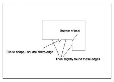


-
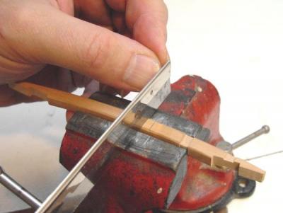
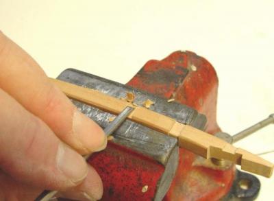
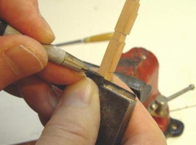
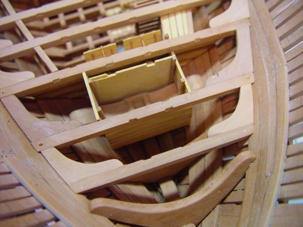
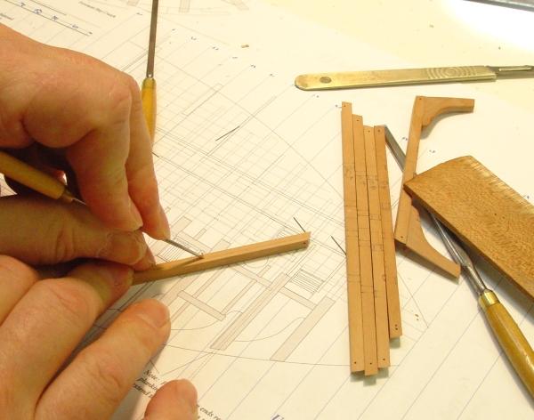
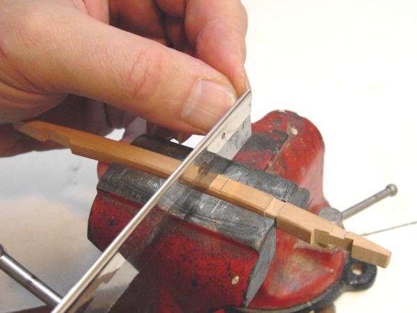
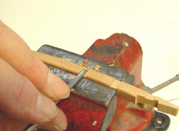
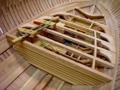
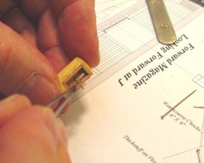
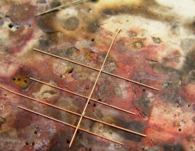
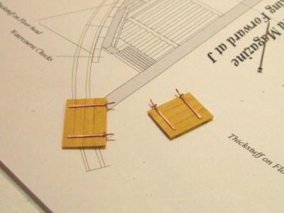
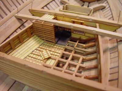
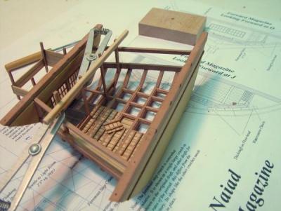
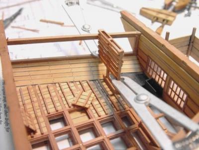
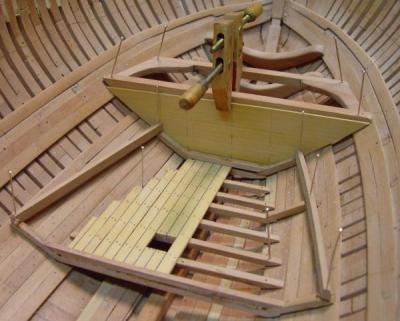
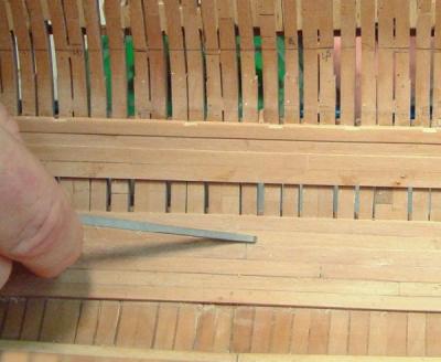
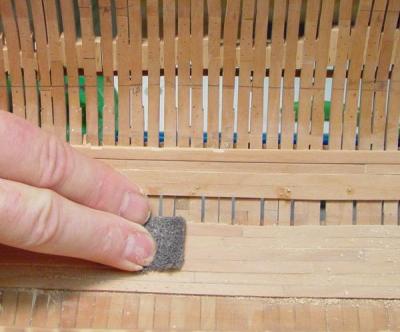
1:60 HMS Naiad 1797 Part 39 – Forward Magazine Wrap Up Posted 1/11/11 This part will wrap up the remaining construction work on the magazine and light room. I will not go through all the gory details, but focus on a few items that may be of interest. This structure has involved a lot of very small-scale carpentry where the labor hours per pound of wood was quite high, but otherwise it was pretty straightforward following the detailed drawing. In the first picture the perforated water stops are being installed. The purpose of these was to dampen the flow of large volumes of water to the underside of the magazine decks while allowing drainage from the sides of the ship down into the limber channel. These will be hardly visible in the model but having gone this far this was no time to stop with the authenticity. The next picture shows the structure on the bench after the installation of the cartridge rack on the port side. Recall that on the starboard side of the ship only basic framing (with a few exceptions) will be modeled. These racks are rather small and won’t be very visible so the were modeled simply. There is a drawer front at the bottom of the rack – I believe its purpose was to collect powder dropping from the shelves above. Above the drawer are shelves with a face board to keep the stored cartridges from falling out. This picture also shows the walls of the light room planked most of the way up. Toward the upper part of this assembly some of the components begin to interfere with beams and carlings so some parts will have to be cut to fit around these members later. The next picture shows the fabrication of the lantern windowpanes. These will be virtually impossible to see as soon as they are installed so they were modeled simply without too much fussing – no glass. This picture shows the mullions for the lantern panes fabricated and ready to be cut to fit inside the frames. These were made from small strips notched, fit together then glued. When dry they were sanded so their parts were flush under my finger on a flat sanding board with 220 grit paper. In the next picture a mullion assembly is being fit up. After these were glued in, the lanterns were sanded to even out the windows with the sides of the lanterns. For something this hidden, this approach was easier than making perfectly fit sash. The next few pictures show the way simple hinges were made for the shutters that could be used to close off the light room windows. I guess this was an additional safety feature. I am sure it was pitch black in the magazine with the shutters down so they were probably only for emergency or perhaps when the magazine was not in use. The first picture shows a grid of 24 gauge copper wire laid out with small blobs of silver solder/flux paste at the joints just about to be touched lightly with the torch . Once these pieces were soldered they were dropped into 5% white vinegar to pickle them and remove the soldering residues. They were then clipped into pieces as shown below with the small wire piece representing the hinge pin assembly. This future hinge is waiting on the anvil to have the long hinge strap flattened. When this was done the hinges were CA glued to the shutters as shown in the picture below. To install these, small holes were drilled in the top of the window frame, the ends of the hinges inserted and then touched with a small drop of CA to keep them in place. Sorry, no bolts. The following picture shows the completed magazine and light room assembly except for a very little bit of light room planking. The finished assembly was given a finish of beeswax diluted with turpentine then buffed with a dry brush – but not near surfaces that would still have gluing. The next picture shows this temporarily (again) in place in the hull. At this stage the assembly needed to be fit up against the beam bottoms and the hull planking so it could be adjusted for correct fit and also to clear the various overhead components. Notice in this picture that the starboard shutter has been raised up so it will just touch the carling that fits over it. This was done to allow clearance for use of the ladder to the orlop scuttle. If left in the lower position it would block the use of the ladder. This place was really cramped for space. I believe I will raise the other on e as well considering that it is a head knocker in the work area. The last picture shows an overhead view with all the main beams fit into place. The tops of the two lanterns are just visible. This is about the only possible view of them. This completed assembly is now ready to be permanently installed in the hull along with the beams and the rest of the lodging knees. Then the closing pieces that fit between the beams on the side bulkhead lintels and the ladders to the light room and the magazine will be installed. The magazine will then be complete. I will cover this installation and hopefully the start of work on the well in the next part. Cheers, Ed Copyright 2013 Edward J Tosti


-
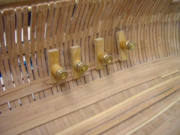
1:60 HMS Naiad 1797 Part 38 – Forward Magazine 6 Posted 1/5/11 The work on the forward magazine continues. In the picture below, the magazine assembly with the two beams that were permanently attached in the last part has been set in place and indexed by the pins through the ends of the beams, which were installed when the beams were first fit up. The port side panel lintel lintel (the top piece) has been installed. This was done in place to assure that both bulkheads remained aligned with their beams. The above picture also shows the new fully leaded sheathed cartridge-filling tub – half of it. The treenailing of the slanted planking has also been done using 1” (.016”) bamboo treenails. In the next picture the other beams have been placed in their positions to make sure everything fits as it should – and it does. The assembly was then again returned to the bench for the construction of the battened partition between the pallet area and the filling room. Intallation of the vertical posts for this partition is shown below. A temporary strip of straight pine was glued to the tops of all these posts to keep them in line. They will soon be cut off at the height of the bottom of the orlop planking – after some, more permanent, support is provided. This picture also shows some concurrent work on the light room partitions in progress. Working both these structures helps keep things moving while glue is setting. Ultimately, I decided to omit the starboard side of the partition. This is in keeping with the “framing only” plan for that side, but also this partition is very fragile and will have no additional support since it abuts the orlop planking and there will be no planking on this side. The port side partition is also fragile but will be supported eventually by some orlop planking. The next picture shows work on the port partition. The battens are very small and their spacing is done by eye only. The following pictures show the assembly in position in the hull. In the next pictures the work on the wing panel stanchions and the battens on the aft bulkhead has also progressed. The stanchions were rabbeted on the two outside corners to set the wing panels. These were done with two separate pieces as was done on the pallet beams. There are a few items left to finish with the magazine. These include the waterproof wing panels, the perforated boards at their outside base, the remaining battens on the partition and the port cartridge rack. Then after finishing the light room, this whole assembly will be installed permanently in the hull. Somehow progress seems slow at this stage, even though the work has been steady. Stay tuned, Ed Copyright 2013 Edward J Tosti


-
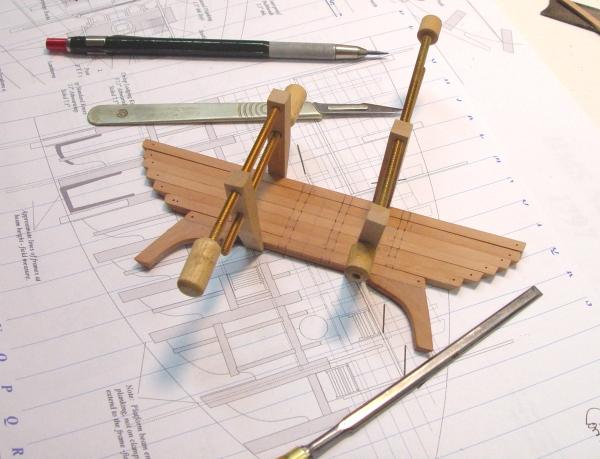
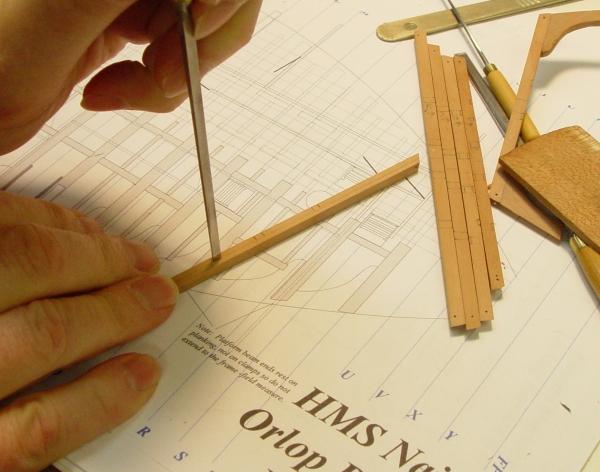
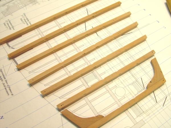
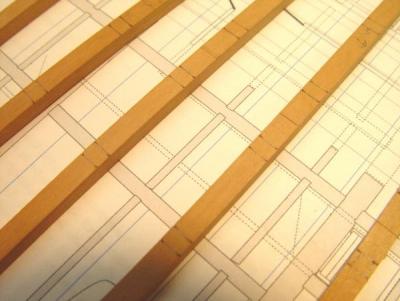
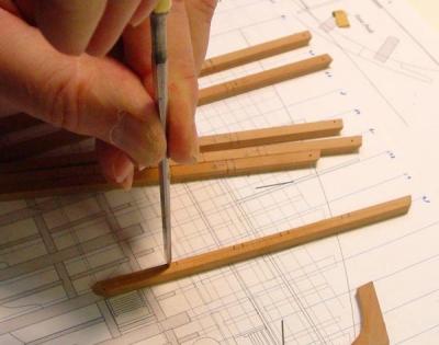
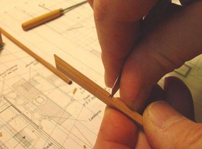
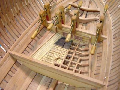
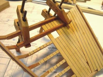
1:60 HMS Naiad 1797 Part 37 – Forward Magazine 5 Posted 1/2/11 It was now time to attach the magazine assembly to the orlop beams at the fore and aft bulkheads for a number of reasons. First, I could then use the index holes in the beams to index the beam/magazine structure. This would assure that everything would fit together when finished. Also, the side wing panel lintels attach to both the assembly and the orlop beams, so the fit would be easier and better if the beams and the magazine were joined in one assembly that could be worked on at the bench. Before attaching the beams, the scores for the carlings needed to be cut. This was done for all the platform beams at this time. The next pictures illustrate this process. First all the platform beams were set in place in the hull and their centerlines were scribed on the top faces. Then the beams were clamped together as shown above for marking out the carlings to assure that these would be parallel when installed. The drawing print in the above picture shows the carlings and ledges for the forward platform. The carlings were 7 inches across. The first beam is clamped backwards because it has already had its lodging knees installed – but its carlings are symmetrical so not to worry. The next picture shows how the location of the carlings on the fore and aft faces were marked with pencil then a sharp knife on the corners. All of these joints were cut manually with chisels. It took about an hour in total. The first step is shown below. First a horizontal pencil line at the bottoms of the 5” deep carlings was drawn on both faces of each beam. A chisel cut was then made vertically for the carling sides a shown. A cut was then made for the bottoms in the same way as shown below. A small chisel and a knife were used to cut out the joint as shown in the next two pictures. In this picture the paring is done from the center to the joint line with the grain to avoid any tear out. A knife blade was also used to clean up the joints. The goal here was to get the heavy cutting out of the way on the bench, leaving perhaps some minor paring to be done when the carlings ultimately get fitted with the beams in place. The next picture shows the finished beams. In the next picture the aft beam has been attached to the bulkhead and the forward bulkhead is being glued to its beam. Both beams were fixed tightly in position for this step and the magazine was fit down on its bedding. For the aft beam, which has its bottom resting on the bulkhead, this fit was done by means of a cross member on the bulkhead which was sanded down until the assembly fit snuggly top and bottom. The forward bulkhead rests on the aft face of its beam so could be positioned vertically before gluing. The next picture taken from directly above, shows the magazine in its correct position, indexed now by the pins at the ends of the two beams. This picture also just barely shows the improved filling tub at the fore end of the filling room. I decided that this tub was more than likely sheathed inside and out with lead, so it was made from brass this time and then blackened. The next picture shows a closer view with all the beams temporarily in place. At this point the heights of the beams were rechecked to make sure the deck would be flat. In the next part the wing panels will be installed under the bottoms of the beams and filled in between them. Ed


-
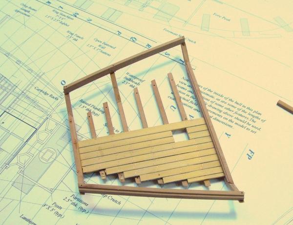
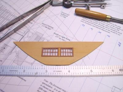
1:60 HMS Naiad 1797 Part 36 – Forward Magazine 4 Posted 12/31/10 By Christmas the deck areas of the forward magazine were pretty well completed. The next step was to construct the fore and aft waterproof bulkheads. The base structure for the forward bulkhead, which separates the filling room from the light room is shown below after the window was constructed. These bulkheads were 2.5” thick, of planks that were lapped and then covered with 1.5” X 3” planks on top of the joints on both sides. Since the 2.5” plank joints would be invisible, the bulkheads were made from a single wide sheet of 2.5” boxwood. The windows were made as follows: First the full opening was cut in the boxwood sheet. The main window frames were then cut and fit into place with a boxwood post in between the two main window panels – which are not the same size. A single rectangle of clear plastic sheet was then fit into each open space. I am not sure of the material. It was cut from the clear covers used on office binders. It is resistant to acetone and ethanol, but adheres to CA. Nice qualities. The outer frame of the window mullions, about 1” square, were then glued around the perimeter of each opening on both sides to retain the glazing. So far all this was glued with Titebond. The 9 vertical pane mullions were then cut and gently force fit into place on both windows. When spaced and aligned, the joints with the frame were touched with thin CA. Some of this, of course ran down between the verticals and the glass. When dry, a 1” notch was cut out of each vertical at the center to fit the horizontal mullion. This was then pressed in and the joints touched with CA. The windows were then cleaned as well as possible with acetone (for the CA) and ethanol (for the Titebond). They still look like they need a cleaning, but are not too bad considering where they are located. In this picture the forward bulkhead is being test fit. The planking up the angled port side remains to be completed. I was not happy with the tub and it would soon come out to be replaced. In the next picture the part of aft bulkhead base panel is being fit up. It was then attached to the aft end of the assembly. These bulkheads needed to be installed so the side panels and their stanchions as well as the partition between the pallet area and the filling room would have good support at their ends. In the next picture the supporting pillars for the aft bulkhead are being installed. In the next picture the planking has been glued on up the port side and the forward bulkhead is being glued on. During all these steps the assembly was indexed at its correct position using pins, two of which can be seen at the aft ends of the wing panels sills. The next picture shows the whole assembly back on the bench. In this picture the horizontal battens have been installed on the fore side of the aft bulkhead and both sides of the fore bulkhead, which also has posts to support the light room sides installed on its fore face. Two loose pallets have been placed in the area as well. The side planking has been leveled off and awaits treenailing. The last picture shows the assembly back in place in the hull. Before any further construction, the assembly needed to be attached to the orlop beams at the tops of the two bulkheads. This would provide a better means of indexing and would assure that final installation would fit well with both the orlop beams, which support the tops of the bulkheads, and also the magazine lower beams, which of course, need to fit tightly on the thickstuff below. Attachment to these beams will be covered in the next part. Happy New Year Ed


-
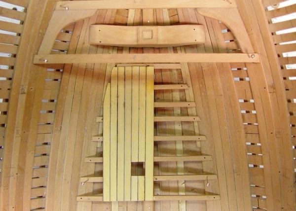
1:60 HMS Naiad 1797 Part 35 – Forward Magazine 3 Posted 12/26/10 In the last segment, the transverse pallet beams were installed on top of the lower level of waterproof planking. The beams were bolted through to the bottom beams with copper bolts. In the picture below the fore and aft beam segments between the transverse beams are being installed. These fore and aft beam segments are also rabbeted on the top corners to take the palleting flats, but in this case, instead of rabbeting these pieces and then cutting all the small joints to fit them in place, separate small strips were installed on their tops on the centerline to simulate these rabbets. Except for a couple that will be left open, the joints on these will not be visible and this saved a lot of time. The key here is to get these very small pieces (1.5” X 3” X about 30” long) cut to the precise length. This was done with a chisel. Then they need to be centered on the beams and lie in a straight fore and aft line – this takes some care. The alignment is done by sighting down the beams at a low angle, like in the next picture – but of course, at the bench where all this small work was done. In the above picture, one pallet has been planked. These planks are 1.5” (.025”) thick and random widths. If I have not mentioned it before, all this boxwood planking was cut from pieces of the correct breadth which had black paper glued to it, so that when a plank was ripped off, one edge would have the black simulated caulking already attached. In this picture the rabbet on the outside of the port lower sill can be seen right next to the locating pin. This will carry 2.5” vertical waterproof panels. In the next picture all of the fore and aft segments are in place. All this work is pretty straightforward micro-carpentry and I will not describe all the gory details. Most of this work is done with a chisel, tweezers and brushes for glue and clean water, once the correct sized members have been ripped on the circular saw. Excess glue, and there is a fair amount, is cleaned off immediately with the dampened water brush. In the next picture more of this small work has been done. At this stage all of the “palleting flats have been planked into the rabbets in the beams, except for two – one to show the scuttle to the limber channel and the one just ahead of it to show the lower planking. Pallets were made for these and will be placed in the area later to show that they have been opened. Once all the pallets were in place the whole floor was leveled off with files and sanded smooth. At this stage the darker boxwood planks were first noticed. Hopefully this will not be noticeable after this area is finished. The next step would be setting the 2” X 2” dunnage beams on top of the flats. These were to keep the stacked powder barrels in place. In the above picture, work has also progressed on the filling room, a smaller two-level area forward of the pallet area. After framing and planking, this area was covered with .005” blackened brass sheet to simulate the lead floor covering used to help keep this area clean of powder. The next two pictures are closer views of this area. There is a row of posts with horizontal boards on each side that will separate the pallet area from the filling room. Mortises for two of these posts can be seen in these pictures. There is also a waterproof bulkhead at the fore end of this room with windows to let in light from the light room just ahead of this area. In the above picture the post mortises can be seen more clearly. Before blackening, the “lead” sheets were scribed to represent joints. Below is a view of this area from above. In the next picture, all the dunnage beams have been installed. There are breaks in these between each pallet so the pallet can be lifted out. After these were installed they were all leveled with a small sanding block. The lead lined wooden tub – half of it that is – has also been installed at the forward end of the recessed area – officially the “filling room.” This area, only half of which is modeled here, is only 4 feet wide in total! Barrels of powder were brought into this space from the palleting area, where they were stored, and emptied into the tub. From this, powder was scooped up by the gunners mates and put into flannel bags, sized to fit specific gun bores. These cartridges were then stored in racks – yet to be built on the raised lead covered area. From there they were dispensed to the powder monkeys through a small hatch to the orlop on the starboard side of this area – also not yet built. In the above picture the first plank of the second layer up the angled sides is also in place. Finishing that planking is next, then perhaps the transverse bulkheads to help support the upper sills running fore and aft at the sides. These in turn will help support the open boarded bulkhead at the forward end of the pallet area. There is still quite a bit to do to finish this area. This work was finished just before Christmas - so perhaps there will be a few days respite bfore going on into 2011. Happy New Year! Ed


-
1:60 HMS Naiad 1797 Part 34 – Forward Magazine 2 Posted 12/21/10 After setting the beams and locking them together with the lower planking, the next step was to install the watercourse chocks. These are timbers, which run up the side and support an extension of the lower watertight planking on both sides. Water can run between these timbers, below the planking, to reach the limber passage and the flow to the pumps. In the first picture five of these have been glued on at the fore and aft ends plus one in the middle starboard side to provide for pinning the two sills at the right curvature. The sills will support 2.5” watertight panels on the outside. To do this they have a rabbet on the upper outside corner to take these panels. The rabbet provides resistance against water pressure from outside the magazine – if it reaches that level or if the ship rolls and water surges up from below. Eventually there will be a perforated board added at the ends of the water course chocks with holes to allow water to flow down but also limit a sudden flow back up, which could blow in the panels and flood the magazine. All this was very low in the ship. Above the two sills, one for each side are bent together to help with symmetry – if they can just be oriented correctly for bending – sometimes confusing. After the bent sills had dried out, they were attached to the chocks as shown below. The next picture shows the base of the forward bulkhead being fit up. This was built up from individual overlapped 2.5 inch planks, but since all the joints were covered with 3 inch boards and will be hidden, this is being made from one piece. All of the light wood in these pictures is European Boxwood. In this picture two of the palleting beams of the upper grid, at the forward and aft ends have been installed on top of the planking to add more strength. On the starboard side, under the aft beam a row of plank segments has been installed under that beam. This will be done on all these beams to show that they bed on planking. In the next picture the assembly has moved to the bench for the installation of all the remaining watercourse chocks. After these were installed it was moved back to the ship. In this position the new pieces could be checked and adjusted. The protruding ends of the chocks were soon trimmed back to the sill with a vertical face to take the perforated boards. The assembly at this point was fairly rigid, but to strengthen it further, all of the timbers, chocks and sills were all through bolt with copper bolts held with CA glue. The next step was to install the thick planking up the starboard side. In the next picture the last of that planking is being glued in place. And the finished planking. Note the planking segments running across the starboard side of the beams. This is a model feature to show that the next level of beams, the “palleting beams,” are placed on top of the lower watertight planking. Since the planking running up the side will have another layer of thinner planking right on top of it, no copper nails will be installed until the second layer is on. The next task is to lay the palleting beams. These are rabbeted on the two top corners to take the “palleting flats,” removable squares of thinner planking that make up the floor of the magazine. Here the first of these is being installed. And the last. After cleaning all this up, the next step will be to install fore and aft cross beam segments to form the four sided support for the pallets. This will probably be the last installment before Christmas. Happy Holidays everyone! Ed


-
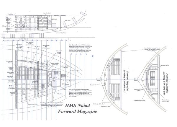
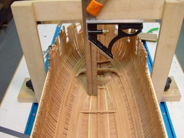
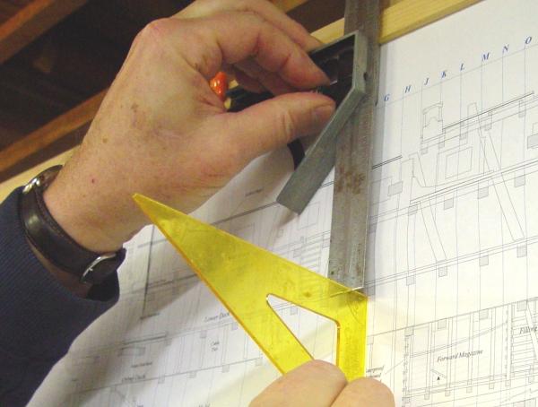
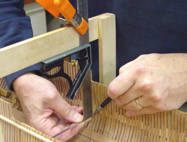
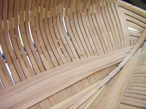
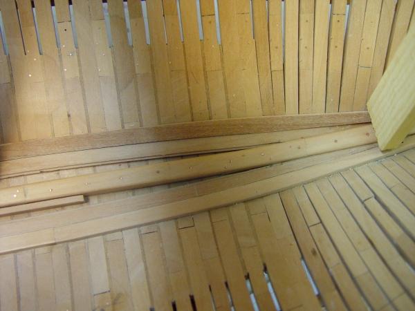
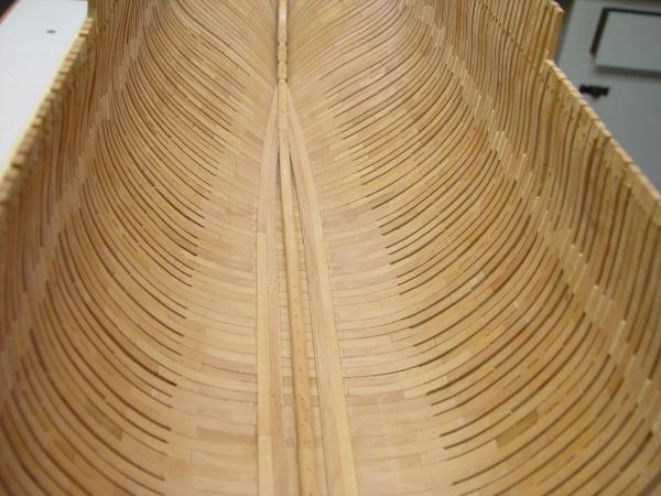
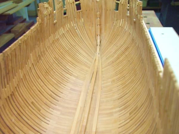
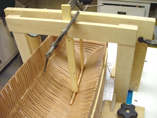
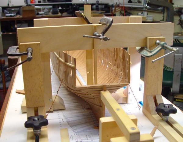
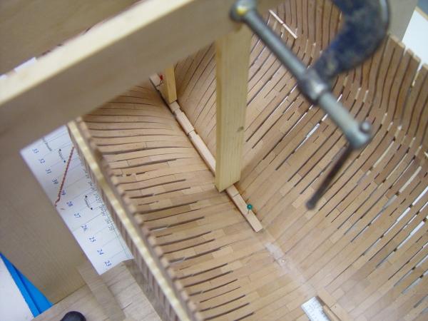
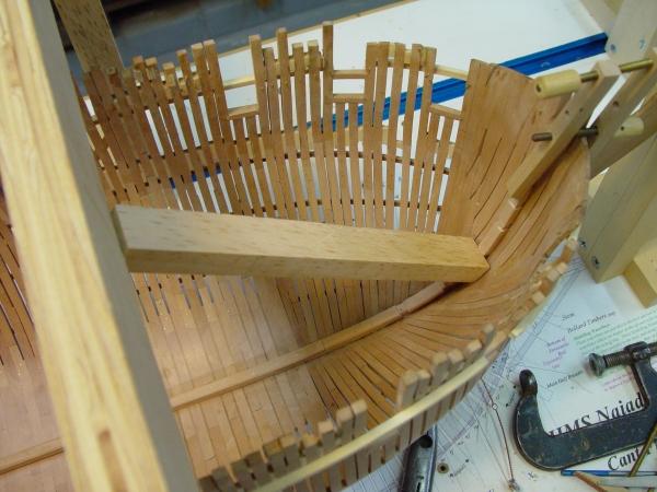
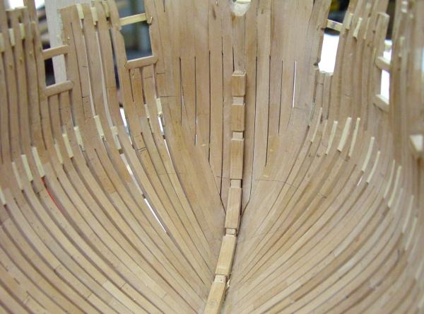
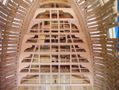
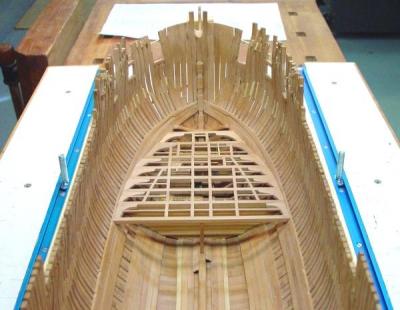
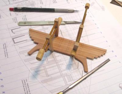
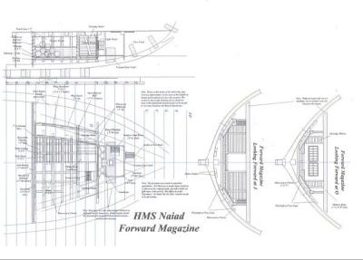
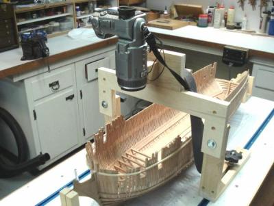
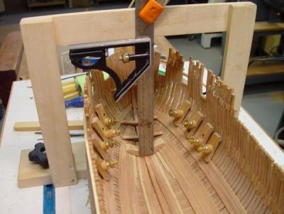
1:60 HMS Naiad 1797 Part 33 – Forward Magazine 1 Posted 12/19/10 Preparation and Drafting The forward magazine is perhaps the most intricate and one of the more interesting structures in the ship. Buried deep just above the keelson, it was the place where the gunpowder was stored and assembled into cartridges. It was the main point where these cartridges were dispensed for use. The carriers, usually young boys, collected the cartridges here, tucked them into their shirts and hurried back through the narrow passages and up the ladders to the waiting gun crews. Clearly the magazine was a vitally important part of a warship that depended on an efficient and timely supply of powder, in the form of pre assembled cartridges, to support the gunnery. The space was cramped, poorly ventilated and accessible through only a single small hatch up to the orlop deck level. Two primary considerations are reflected in its design and these evolved over a long period of time, punctuated by accidents of the worst kind. The first of these concerns was the safe handling and storage of the powder away from any sources of ignition, which could result in an explosion, which would destroy the ship. The second was the need to keep the powder dry to avoid it becoming useless. The main features of the design to meet these needs were: solid watertight bulkheads at the fore and aft ends of the area and below it, multiple levels of decking to keep water out and to allow access for cleaning of spilled powder, a source of light from large lanterns completely isolated from the area and a single small access hatch from the deck above. There were many other features of course, and these may be explored on the following drawing, which was prepared from as many sources as I could access before starting work. The drawing above is only the latest in a line of several revisions. A preliminary version was posted earlier and responses to it have been very helpful in settling some details. There is more work to be done on this. Some of the lateral dimensions on the plan view are not precise and will be “field checked” for construction. This avoided a lot of complicated unnecessary drafting. These approximate dimensions will be corrected on the drawings from measurement taken on the as built model. The vertical dimensions from the sections are correct and sufficient for construction. This is a very detailed and interesting structure, but in the final model it will be buried under upper structures and difficult to see. For that reason I wanted a very good photo record of it at each stage of the work. To that end, a fixture was made to support my camera so that consistent views from directly above and at a few other angles could be taken during construction. Here is a picture of the fixture. This fixture bolts to the “clamped squares”(not the gantry) that I have discussed previously. It can move forward and aft to marked positions on the board and the camera can be tilted forward and back on the hinged mount to four preset positions – vertical, 45, 30 and 15 degrees. Deciding how to make the magazine structure was another part of the preparation. I definitely wanted to build this on the workbench, not in place on the ship. It is not easy to construct something like this reaching over the model. Although I could not foresee a full plan for this in detail, it was clear that the basic framework would need to be built in place, removable so it could be taken back to the bench. A sturdy assembly starting with the lowest level of beams would be the basis for this. I used this approach on the stern galleries of Victory. Construction The first step was to install the forward platform beams at the orlop level above the magazine. The magazine bulkheads tie into these and it seemed logical to make these first. They would be installed much later, however. Here is a picture of these beams taken from the fixture described above from directly overhead. These platform beams do not rest on a clamp per se. Instead their beveled ends butt right onto planking of the orlop clamp and upper band of thickstuff, both of which were described earlier, so locating the ends of these beams required setting points on the side in all three dimensions. This was done from the profile drawing using the gantry device and a combination square. I will describe the process in more detail below as it relates to setting the magazine beams – a more challenging task because of their size and the shallowness of the hull toward the bottom.. Setting any points involves some degree of measurement error and this needs to be managed. One way to minimize the effect of error is to avoid multiplying it by taking measurements from points on the model that were set out earlier. So, all measurements were taken directly from the drawings whenever possible. Also, whenever possible, dimensions were checked against other parts of the structure – but direct transfer from the drawings was the rule. One advantage of CAD is that the very fine lines and the dimensional accuracy help reduce measurement error. Once the forward and aft beams were set and checked thoroughly, the remaining beams were adjusted to fall into a line along the tops of these end beams. This is virtually a straight line on the orlop level. This was done with a straight piece of wood as shown below. The next step was to set out the locations of the lower beams of the magazine itself. The process was as follows: First the distance to the aft side of every beam was measured from frame lines on the drawing with dividers and transferred to both sides of the building board. The gantry was then aligned with these marks, one beam at a time. The distance from the top datum line on the drawing to the top of the beam was then set on a combination square. This square was then held on the bottom of the crossbar on the gantry so that the fore face of the square’s ruler was aligned with the aft side of the beam. The square was then traversed until the bottom fore face of the ruler touched the side. A point representing the aft upper face of the beam was placed at this intersection. This was done for both ends of all the beams. The next picture shows this point being set for the port side of the second beam aft, which will rest on the boxwood ceiling planking adjacent to the limber strakes. These beams are very low. The most forward beam just touches the top of the keelson.. For this process to produce accurate results the gantry cross bar needs to be straight, level and the bottom face precisely the same distance above the board as the datum line on the drawing is above the bottom of keel line. The vertical legs supporting the bar and the face of the bar itself need to be at 90 degrees to the board and the surface of the board needs to be clean of debris – especially dried glue blobs. Finally when the aft faces of the two bases of the gantry are placed on a line on the board, the aft side of the crossbar needs to correspond precisely to that line. Some of this needs to be attended to when making the gantry, but before doing something like this, I recheck all the above. So, when the ruler of the combination square is clamped to the bar with the square pulled up to the bottom, the ruler, which was extended to the length of the drawing measurement, should be right on the line to set the point. In the next picture the fore and aft beams have been made and set in place on their corner points. Dividers were used to determine their maximum length and the ends were beveled to fit the planking. Succeding beams were fit the same way, but had their length adjusted as needed to align the top edges with the first two to assure a flat deck. The next picture shows all the beams in place, being checked for consistent height. The next step was to begin locking these beams together into a sturdy assembly that could be transferred to the bench. On the model, I intend to at least partially plank the decks on the port side, and leave the starboard side completely open, showing only framing. It begins here. This is the lower level decking – 2.5” thick. It will be covered with a matrix of beams and the palleting layer of planks. The small hatch in the decking is to allow access to the lower regions for clean out. To further strengthen this base assembly, it was removed from the ship and copper nails were installed on the workbench. Then back to the model as shown below. Another check was performed and is shown in the next picture. In this picture a small special gauge is being used to check the distance from the top of the lower planking to the bottom of the orlop beam above. Thankfully, perhaps luckily, it was a precise fit on every beam. Now more of this structure needed to be built up in place to match the hull, specifically the water course chocks which run up the side from the beam ends and also the curved horizontal sills that will tie the upper ends of those together. A few of these pieces are in place in the above picture. This and subsequent steps will be covered in the next parts. Stay tuned. Ed


-
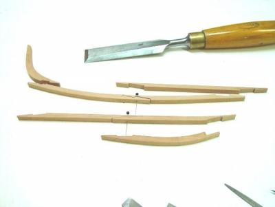
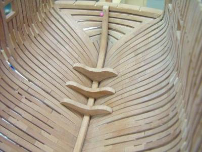
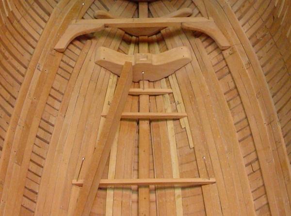
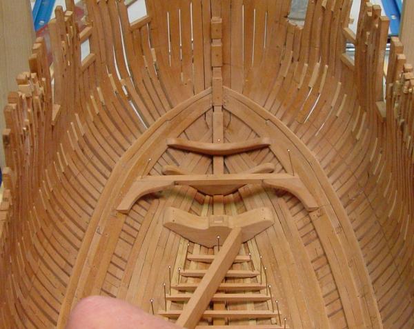
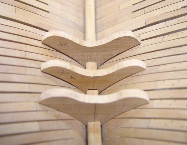
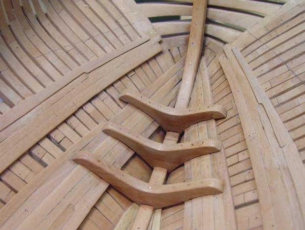
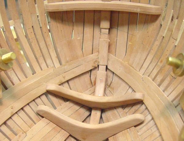
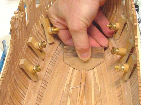
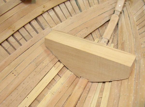
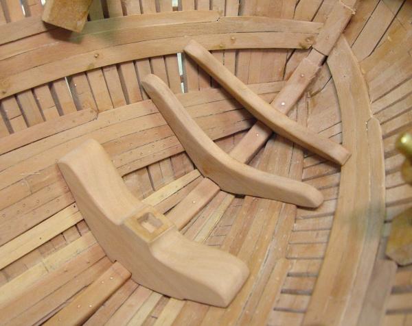
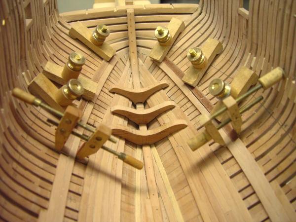
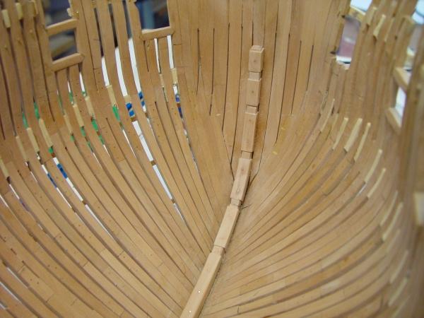
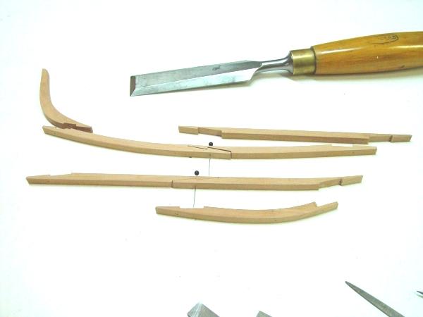
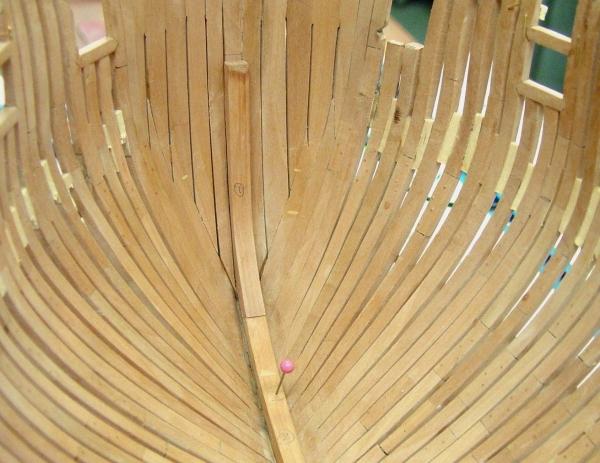
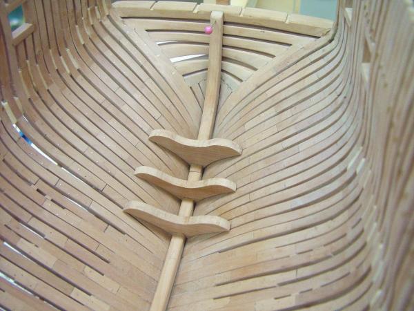
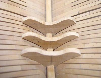
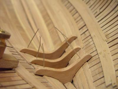
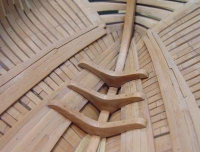
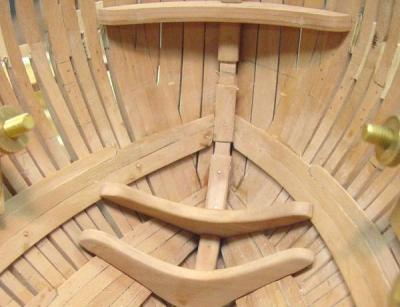
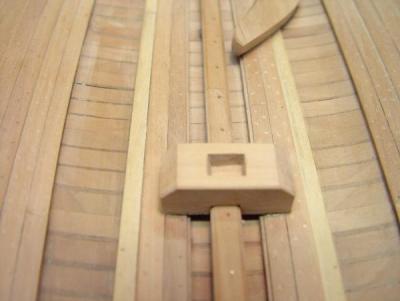
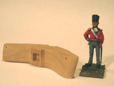
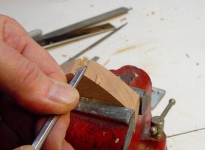
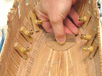
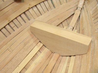
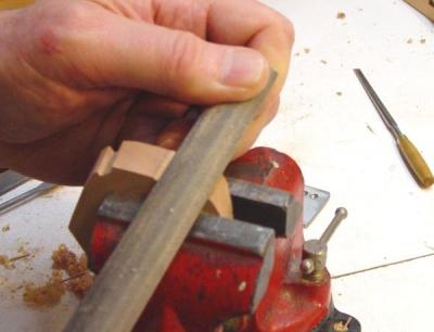
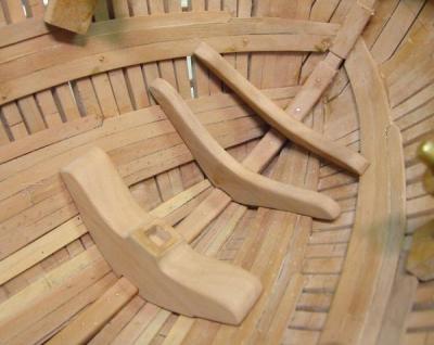
1:60 HMS Naiad 1797 Part 32 – Crutches, Hooks, Steps Posted 12/18/10 Crutches The crutches and breast hooks were relatively easy to make, but required a lot of fitting of the joining surfaces with the planking. All of these except the deck hooks were fayed on top of the planking. In the picture below, taken before any planking the three crutches were roughly fit up to the framing and then labeled and put away for later. No patterns were needed for these. They were cut to thicknesses and lengths based upon Repository dimensions. The bottom edges were sketched in by eye and cut on the scroll saw and then shaped roughly with sanding blocks. The upper shapes were left very generous at this stage. As seen in the next picture these pieces were subjected to a lot of additional shaping to fit over the planking. This was done with chisels, files and sandpaper blocks. Where they overlap unplanked areas there is a space. What is wrong with this picture? The middle crutch is too small in length, the result of unclear labeling when the blanks were initially fitted. This was actually one of the breast hooks of similar shape. So, another piece for the rejected parts bin – now beginning to overflow. The following picture was taken after this piece was replaced. In this picture the crutches have been bolted with nine copper bolts each. These would have penetrated through the planking and frames, of course. I did not trust my drilling to find the right exit point, so these do not go all the way. I may put dummies in from the outside – still thinking. BreastHooks These were done in exactly the same way as the crutches. The lower two only were installed at this time. The higher ones will be done when the next bands of planking, the lower decks clamps, are finished. Mast Steps Lets take the easy one first. The main mast step is just a big block of wood of rectangular shape that rests on the keelson. It is about two and a half feet wide and its length is set to just clear the posts in the future well. It is not bolted. It was quite easy to make and here it is in place. This step will eventually be concealed within the well. The foremast step was a much more interesting proposition and some sticky questions had to be addressed. Fortunately this is buried so deep in the ship that much of the design uncertainty may be of little consequence, but it was an issue. The design of this step was raised on another log, SJSoanes Belona build at http://modelshipworld.com/phpBB2/viewtopic.php?t=11226 A very interesting and helpful dialogue ensued, which I believe helped both Mark and me settle our particular, and different, design solutions. Briefly, for Naiad it was not clear what this step looked like. The original profile draft for Naiad and many other frigate profiles show a single block, like a hook, but about 26 inches breadth. It is pretty clear that this was used on small ships - 36 guns or less. A step made up of multiple crutches and other pieces was used on larger ships. Where did this leave the 38 gun Naiad? The use of a single block would have been clear, to me at least, except that David White in his book {I} Diana{/I}, also a 38 and of the same vintage as Naiad, shows a built up step like the larger ships. Since Henslow and Rule, the designers of Diana and Naiad respectively, were surveyors at the same time, one could conclude that they might adopt similar designs. Where did White get his design? Was the single step on the Naiad and other drafts only schematic? I have not seen an original profile for Diana and wonder what it shows. It was clear however, from the Naiad draft, that a built up step would not fit without moving the whole magazine or moving the foremast. The magazine and, of course, the foremast locations are clearly shown on the Naiad draft and I did not want to move them.. After trying to fit alternates on the drawings and some soul searching, I finally decided on the single step shown on the drawing. It is a substantial piece of wood, shown below next to one of my 1:60 friends. The piece in this picture is just over 30 inches broad and was subsequently taken down some to reach the specified 26 inches. I have spent some time in Kent and Sussex and have seen plenty of ancient oak trees from which such a piece could be cut. It is just a big block taking a compression load, so I don’t think curved timber was mandatory, but … So, with that decided here are some pictures of the piece being made. After rough cutting the block, the slot over the keelson was cut with saw and chisels – pictured above. Then the trips back and forth from ship to vise begin. Here the rough block is being test fit. Here a little more shaping has been done. The hard part here is to get a tight joint over the irregular planking. Some of my pencil notations for more shaping are visible on the bottom. Here the irregular bottom is being shaped with a file – a bigger one than usual. Once a satisfactory fit at the bottom was achieved, the top was shaped and the mortise for the mast tenon cut. Below the step is shown resting in position, well, just a little aft of position. It still had to be taken down in width and glued and bolted in place. In the next picture the final fore and aft location is being set using the gantry and combination square. And in this next picture it is being held down after gluing. Finally it is in place, soon I hope, to be entombed safely under the light room decking. In the next part I will discuss the design, drafting and the beginning of construction for one of the most important, interesting and intricate structures in the ship – the forward magazine. Ed

-
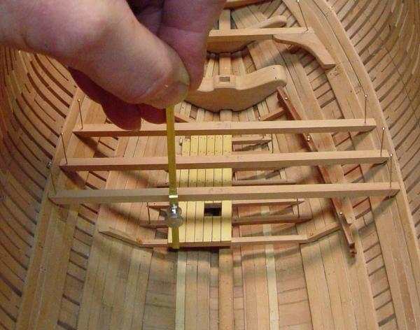
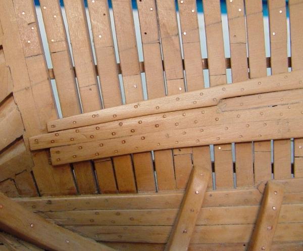
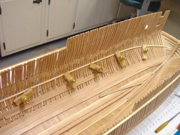
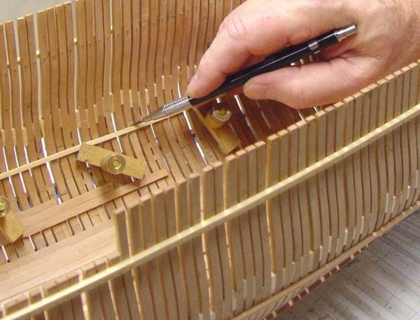
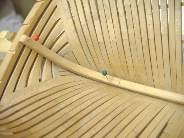
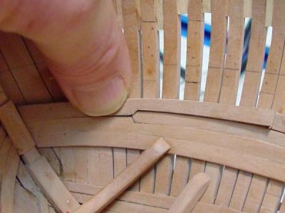
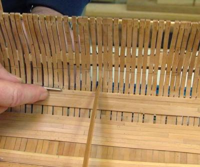
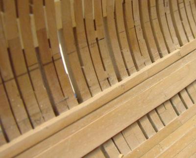
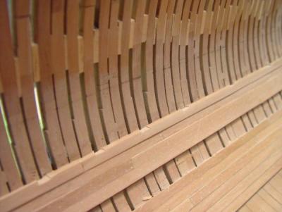
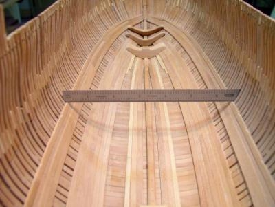
1:60 HMS Naiad 1797 Part 31 - Orlop Clamps Posted 12/16/10 The orlop clamps rest right on top of the highest band of thickstuff, on the upper 4” thick strake. The clamp itself is 5” thick and as mentioned earlier it only serves as a support for the middle platform of the orlop level, which I surmise was officially “the orlop.” The fore and aft platform beams, carrying only light loads, had their ends bearing on whatever strake of planking happened to be at their level. The orlop clamps were installed concurrently with the upper band of thickstuff. The next couple of pictures show some of the clamp sections being attached. In the above photo the last full breadth piece forward is being glued in place. From here forward it narrows and thins. The narrowing to meet the upper center band of thickstuff is seen in the next picture. In this picture the very last piece is being fit up. First the plank was steamed and clamped to dry to the right curvature. It was then trimmed to the shape shown above and fit to match the adjoining planks and the forward width was reduced where it meets the stem. After gluing the forward part was thinned to around 3” per the Repository. With the clamps completely installed, the section that supports the center platform, needed to have its upper edge dubbed horizontal to take the beams and lodging knees. The next two pictures show this being done. In this picture a thin straight strip of wood is laid between the frames and on the clamps to act as a guide for leveling their tops. In the next picture a small chisel is being used to pare the inside upper corner to the same level as the outside top of the strake. This paring was done only between the fore edge of the first beam and the aft edge of the last beam aft. This can be seen in the next picture. This is a picture of the starboard clamp after the top had been dubbed off. The end of the horizontal section can be seen to the right just above the number 6, which denotes the last beam aft. The difference in thickness of the planks in this band shows well in this picture. Some treenailing is yet to be done in this area. The height of all this planking was set to bring the top of the clamp slightly higher than the bottom of beam line. When the clamp was then scored down to take the beams, they would then be at the correct level. The following picture shows the scores for the beams cut into the clamp. These scores were cut, in place, with a small chisel, having first been located and marked to the width of the beams, which are 11 inches wide and 10 inches deep. In the next picture, a ruler has been slid between frames to measure the overall beam length. From these measurements, each beam was cut to length. The next picture shows these lying in place temporarily. The outside ends have been beveled to match the frames. The specified round up of these beams, 1 inch, is so small at this scale that it was ignored and for this level the beams will be flat. These beams will be installed permanently later. They were made at this time to be used in constructing the well, one of the next steps. In the next part I will review making and installing of the crutches, breast hooks and mast steps, which were shown in many of the preceding pictures, Ed

-
You're welcome, Martin. Volume II is progressing well. I am hoping to see it in print this year, but sometimes schedules are hard to predict. It is about half written, but of course I need to finish the model as well. I hope you are finding Volume I useful. Ed
-
Hi Mark, Going through your reposted pics is like going down memory lane. Ed
-
I love your work, Remco. Its good to see you back up. Ed
- 1,215 replies
-
- 1
-

-
- sloop
- kingfisher
- (and 1 more)
-
Looking forward to this, Joss. Ed
-
The Naiad Frigate – Addendum 1 I will be posting addenda to The Naiad Frigate – Volume I when important corrections are needed or there is value in additional information. This is the first of these. Text correction: 92, column 2, paragraph 1: “having the transoms” should read “having the fashion pieces” Drawing corrections: Discard pattern sheet for Frame 1F. There is no Frame 1F. The framing drawings are all correct. This sheet was created in error. Replace patterns for the following frames: Frame DF A (toptimber siding note incorrect) use:Naiad 60 Pattern DF A.pdf Frame 3A (joints corrected) use:Naiad 60 Pattern 3A.pdf I would like to thank Jeff Hayes of Hobby mill for pointing out these drawing discrepancies. Jeff is working on a framing package for Naiad and brought these to my attention during his very thorough review of the drawings in preparation of his bill of materials. Sorry for any inconvenience. Ed Copyright 2013 Edward J Tosti
-
HMS Victory by EdT - FINISHED - 1:96 - POB
EdT replied to EdT's topic in - Build logs for subjects built 1751 - 1800
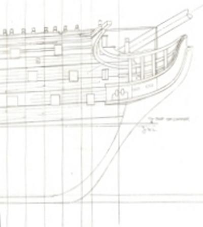
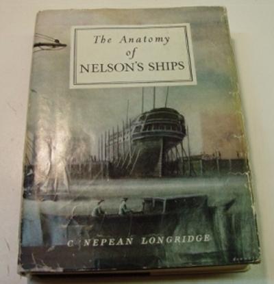
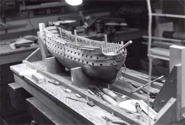
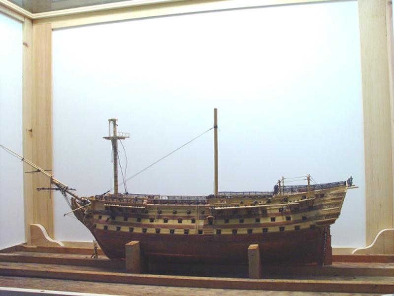
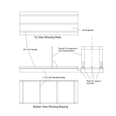
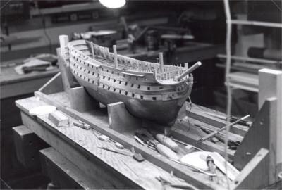
HMS Victory 1:96 Scratchbuild Project Part 2 – Drafting and Preparation The first part of this series was introductory. The remaining parts will, I hope, be much more hands on. As I said in the first part, this will not be a complete “how to scratch build Victory” practicum. Instead, it is my goal to provide a general overview of the stages of the work, but also to focus in-depth on specific work processes or solutions that may be interesting, solve a particular problem, or in general, be helpful to modelers of different levels of expertise. These will be examples of how I solved various problems; there may be better ways. These solutions worked for me. Some I developed; some I simply used or adapted from the ideas of others. Drafting Plans and Patterns The bow scanned from the final Sheer Plan I will touch on drafting only very briefly. In the build log on MSB I went into some detail on this, with a view to helping novice scratch builders with some useful drafting techniques. In it I covered, in some detail, transferring and rescaling body plans accurately from books and developing true views of rotated and curved sections. It was long and perhaps sleep-inducing for some, but if anyone has interest it can be found at http://www.modelshipbuilder.com/e107_plugins/forum/forum_viewtopic.php?1655.10 As I said in Part 1, in 1976 there were limited resources for building a model of this type. I could locate only one set of plans and they were quite expensive and above what I wanted to pay at that time. Also, I had an itch to do the plans myself. It was the beginning of an idea I had that ship modeling would be most rewarding if it encompassed and followed as much of the whole historical process as possible – not just model construction. For me, this approach has been very rewarding. My primary source of information at the beginning of the project was the Longridge book, Anatomy of Nelson’s Ships, which I described in part one. The book includes many diagrams and a set of foldout drawings as well as a complete body plan. This work was done a dozen years or so before the McKay book and plans were available. None of the drawings in the book were to the scale I wanted to build, 1:96 or 1/8” to the foot. In the pre-PC/CAD era I redrafted these plans manually, adding detail and patterns, as necessary. This involved several weeks of effort before modeling could begin and additional work after that. My well worn copy of Longridge, my source for drawings, instruction and inspiration. The basic drawings for the model included the sheer plan, a plan of the model framing, waterlines, individual profiles of the main frame lines, deck plans and sections, and stern/bow decoration. Many other sketches were done from time to time as needed. No drawings were done for masts, spars or rigging. By the time I reached that stage I was able to rely on the McKay book and several other sources for those details, which I will describe later. The Model Shipway Because it was such an important, useful tool over the whole life of the project, I want to describe the construction of the building board, or model shipway. Below is an undimensioned outline drawing of the shipway I built for the Victory model.[/size] A large, 20” x 44” piece of ¾”Douglas fir exterior plywood, sanded one side, was used for the base platform. The length and width were made sufficient to clear the entire model including the bowsprit, driver boom and main yard with studding sail booms. Dry, clear pieces of white pine, ¾” X about 2 ½”, were planed true on one edge and screwed securely to each other and to the plywood top, as shown in the sketch. When this was done a long straightedge was placed on the top across different sections to check for flatness. Where a slight distortion in the top was found, some of the screws were loosened and thin shims inserted to bring the top perfectly flat. After thirty-four years of abuse, standing on its end sometimes for years in my basement, the board was as flat on the day I cut it up for fireplace kindling as it was when it was built. During use the board was securely clamped on my workbench. On the top surface I placed three straight grained ¾” X ¾” oak rails, the first in the center on the line of the keel and the other two outside the maximum half breadth of the hull. The centerline of the keel and all the frame lines were scribed into these rails. To aid in frame alignment, checking of locations, especially within the hull, a carefully squared “gantry” device was built to slide on the outside rails. This could be aligned with the scribed lines on the rails or any point in between and was secured with bolts on either side (not shown in the diagram) that would squeeze the triangular gussets tight to the rails to hold it in position. This device was carefully squared both longitudinally and athwartships and was marked with a scribed centerline in the top horizontal rail. A datum line to match the top of the gantry rail was put on the drawings as a basis for vertical measurements. This device was indispensable for marking out and checking dimensions inside the hull. A combination square could be run along this top rail to set heights and breadths easily. The picture below, taken in 1996, is one of the few I have that shows the board well, without the gantry, unfortunately. Please excuse the bench clutter. In this picture there are two squared up end strong end posts which could be used to stretch a piano wire along the centerline as another way to check the scribed centerline on the “gantry” and to initially center frames on the keel. These were removed when no longer needed. Also shown are felt lined cradles that were added after the lower hull was finished. Before then the hull was squared up by means of doubled copper wire from two lower gun ports on each side attached at their ends by small screwed eyebolts, one end into the board the other into a small piece of hardwood inserted inside gun ports. The wire was then twisted tight on each side until the ship was in proper alignment. This approach allows very fine tuning of the ships vertical position. The model was held in longitudinal alignment by a block on the middle rail at the back of the sternpost. Finally, when rigging started, a temporary case, made from pine and foam board was fitted to the base to completely enclose the model to keep it free of dust. The sides of this or the whole could be removed easily to gain construction access. The top was made from clear acrylic sheet, so overhead ceiling lights could keep the work well lit. The case was fastened to the outside edges of the board. This worked well in what was often a very dusty woodworking shop. It also provided a nice backdrop for a lot of the photos. The picture below shows the model in the case at the start of rigging. The clear Plexiglas top can be seen in the upper left corner and the lighting from above is evident on the back of the case. So much for the preliminaries. In the next part I will discuss the first stages of actual construction. Cheers, Ed Tosti 2013 Copyright Edward J Tosti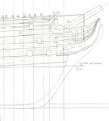


-
HMS Victory by EdT - FINISHED - 1:96 - POB
EdT replied to EdT's topic in - Build logs for subjects built 1751 - 1800
Thank you, both. Druxey, I am sure Longridge was an inspiration to many - a real pioneer. Ed -
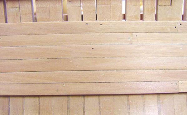
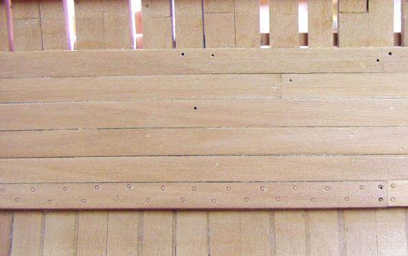
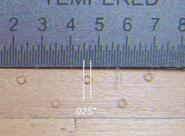
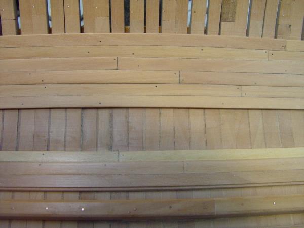
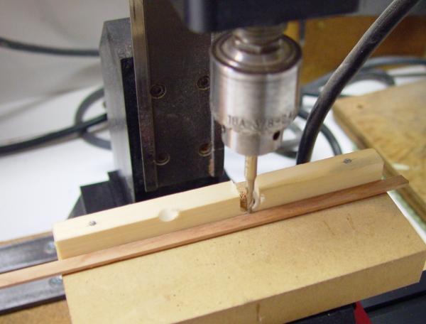
1:60 HMS Naiad 1797 Part 30 – Thickstuff Continued Posted 12/14/10 Welcome back. It seems like a while since the last post. A lot of work has been done concurrently since then. At this stage both bands of thickstuff are finished, shy of a few treenails, the fore and main mast steps are installed, the orlop clamps are installed and scored down for the beams in the center section, the three crutches are installed and two of the forward breast hooks are installed. The picture below shows this overall progress. Because all this work overlapped, I will go back and cover each piece separately. Finishing the Lower Thickstuff Once the lower band of thickstuff was installed, treenails needed to be put in, and the surfaces needed to be sanded and polished. Here are a few pictures of some of that work. In this picture the joint line between the 5” thick central stakes and the upper outside 4” strakes is being cleaned up with a die sinkers riffler, in this case one with teeth only on the bottom face with sides that bevel in on the top. This is very useful for cleaning out corners and in this case helping accentuate the small difference in plank thickness. Here the lower band is being buffed up after sanding using a piece medium grade Scotchbrite pad. These are much cleaner to use than steel wool, which leaves steel particles all over the area and attached magnetically to tools – especially files. My goal with this polishing is to get the wood to look finished without a finish. Unfortunately this is hard to do without some use of steel wool. 000 wool leaves a nice polish as a last step. In this picture holes for bolts in the step are being drilled with the small WeCheer rotary tool. This is the way all the treenail holes were drilled so I included this picture here. This inexpensive little tool has made drilling precisely located holes a pleasure. I also used it on the lower hull bolt holes. It is small enough to hold like a pencil and if placed on the wood at the hole position, as pictured above, and turned on, there is so little torque kick that it is easily kept in place. About five percent of the treenails in all this lower internal planking were “real” treenails and the rest were embossed with a piece of .025” ID hypodermic tubing. This was disussed in the last part. Some of the treenails are boxwood and some are bamboo. I prefer the look of boxwood, since the bamboo nails seem to end up quite dark, but the bamboo are easier to draw without breaking. The above picture shows the aftermost part of the upper band of thickstuff and the orlop clamp. This area will be hidden in the final model and I have used it area to test finishes. The embossed treenails definitely need highlighting to be visible. I first tried some diluted Danish oil on the crutches and the lower band in this area, but this gave the pear such an orange cast that I removed it (well, most of it, with some difficulty). The ends of the three strakes in this picture were treated with beeswax diluted in turpentine. This has been and still is my first choice for finishing, even though it too is a bit yellowish. I have a few more things to try. I have made several test strips with different options, but its really hard to tell until you get it on the model. Upper Thickstuff There are four strakes in the upper band of thickstuff. I decided at first to do only the two middle 5” thick bands, then later decided to add the upper 4” band because it its top edge butts against the orlop clamp, except at the ends where it narrows and the upper center strake meets the clamp. This transition shows in the above picture. Also, I mentioned in the last part that the orlop clamp and the second band needed to come in fair at the ends roughly midway between the lower band and the lower deck clamps so the lower deck line was drawn in to help locate these correctly. In the picture below, the three upper strakes of the upper thickstuff are being fitted up. This picture was taken before the deck line was drawn in. The next picture shows the lower center strakes being glued at the aft end. I elected to stop these before the sternpost to avoid blocking the opening between the transoms, knowing that the ends of these would not be exposed to view in the finished model. The wet spot in this picture is from cleaning off the excess glue with a wet brush. The next picture shows two of the curved after strakes being clamped in place to dry after boiling. Even though these pieces have only a slight curve, they were steamed, to avoid stress in the final assembly. The process here was to cut the plank roughly to length, boil it for 5 minutes or so, depending on how much curvature was needed, then clamp it in place and leave it overnight. Then it could be removed, sanded, trimmed if necessary and glued down. I will cover the orlop clamps in the next part, and then the crutches, hooks and mast steps.


-
1:60 HMS Naiad 1797 Part 29 – Thickstuff Continued Posted 12/6/10 Since the last post, work has proceeded in a few areas concurrently. I’d like to have the internal hull below the Orlop level polished off (literally) by the holidays and be into construction of the forward magazine before the end of the year. Treenailing I mentioned in the last part that there are roughly 3500 treenails in the limber strakes and the lower bands of thick stuff, without even counting the lower futtock-head bands. This got me exploring some other ways to realistically represent all these nails in an area of the ship that will be difficult to see at best. The result will be a combination of real 1 ½” (.025”) treenails and embossed nail heads using hypodermic syringe tubing. The next few pictures illustrate the results of my first attempt at this approach. This first picture shows the two lower strakes with some “real” treenails. They have been installed in all of the holes drilled earlier for the pins. In addition, a lot more, maybe 5% of the total down here in the hold, will be of this type, to provide additional strength to the glued planks. The next picture shows this exact same section of planking with the syringe embossed treatment in the lowest strake.. This approach gives a more pronounced treenail head and for the sake of uniformity it has been applied to the actual treenails as well – almost, that is. A couple cases are slight misses. The next ultra close up picture illustrates the size of the nailheads. Much smaller sizes of syringe are available. So, either of these methods can be used to create accurately sized heads. The question becomes one of appearance – and therefore perhaps one of taste. Any feedback on this would be welcome. The actual treenailing was done in the conventional way. Strips of European Boxwood were drawn down to .025” in a drawplate. (Its still home made. Maybe Santa will get me a Brynes plate.) Some were also done using bamboo stripped down from quite old garden stakes. Both work well. A slightly larger hole was drilled. A #70 drill provides a sliding fit with glue and allows the nail to go to the bottom of the hole. A long treenail strip was dipped in diluted Titebond, inserted as deeply as possible in the hole, slipped in and out if possible to distribute the glue, then clipped off with diagonal clippers, and finally filed and/or sanded off. The embossed version was done using a short length of 19 gauge stainless steel hypodermic syringe tubing, which I happened to have on hand. This is available in a myriad of sizes. I had gotten mine from Small Parts, Inc, but I just ordered more in different sizes from Amazon, who is doing order fulfillment for some Small Parts products. I find them faster and I can take advantage of free shipping. To prepare a piece of syringe, I clipped off a piece about an inch long with diagonal clippers and ground the business end flat. A sharpened bevel was then ground on the O.D. of this end and the I.D. was flared somewhat using a sharp scriber tip. This last step helps avoid pulling the new nail head out with the syringe, leaving an unsightly 1 ½ inch hole (which would have to be filled with a real treenail). The opposite end of the syringe piece was then force fit into a hole in the end of a 1/8” X 3” brass rod, to make handling and control easier. The rod could then be positioned and tapped lightly with a small hammer. Thickstuff on the 1st Futtock Heads Like the first, the second level of thickstuff in Fifth Rates had two center strakes each five inches thick. As mentioned earlier, this was a departure from the more normal configuration that featured one single central strake. The line between the two center strakes was located on the joint at the heads of the first, or lower, futtocks. The heights of this band forward and aft was of some concern to me, because it was not at first clear how this band would mate up to the orlop deck clamp shown on the 1808 draft, until, after some research, I learned that the forward and aft platform beams do not rest on clamps, but rather, their ends fit against planking of either thickstuff or footwaling. Only the center platform has its beams resting on a clamp. This explained why the clamp on the planking expansion diverged from the height of the platforms. The planking expansion is a bit confusing here because the plank labeled “orlop clamp” runs the full length of the ship. Perhaps the center platform, which rests on this clamp, was called the orlop. With this understanding, it was relatively easy to bring the ends of this band in fair. These ends need to fall somewhat under the midpoint between the lower band and the lower deck clamps. So to help locate these, lines were drawn on the inside of the hull at the bottom of the lower deck beam ends. The following pictures show how this was done – and how heights generally have been set off on the inside of the hull. I had originally planned to make a measuring device to transfer these heights, but instead have found that this could be done pretty easily using a combination square as shown in the next two pictures. In this picture a height dimension is being set for the lower deck beam at G from the profile drawing. The bottom of the strip of wood at the top of the drawing was set at the height of the bottom of the “gantry” cross piece. A triangle is used to set the combination square height to the desired point on the drawing. The next picture shows how these dimensions were transferred to the hull. First the gantry was set at the correct frame line on the building board overlay. The combination square with the present height was fixed to the gantry close to the side with a clamp. A small ruler was then used against the bottom of the square rule to set the height at the side, which was then marked with a sharp pencil. When a sufficient number of these points were marked out, a pine batten was clamped along these points. This batten was checked for fairness visually and a few points double checked along its length. Also in this picture the second band of thickstuff is being installed from the midship area area, waiting for the lines to be set at the ends. The planking clamps shown in this picture are working so well I made ten more to add to the original seven, allowing more work to go in parallel. The next picture is a closer view showing how the line mates with the bottom of the lower deck transom at the stern. Finally the lower deck line was penciled in. With this line drawn, the run of the second band of thickstuff at the ends could be positioned. In the next part I will cover the completion of those bands, and some of the other work being done in parallel. I am happy to say that we are now caught up with the actual progress – so future posts will reflect current progress. Ed
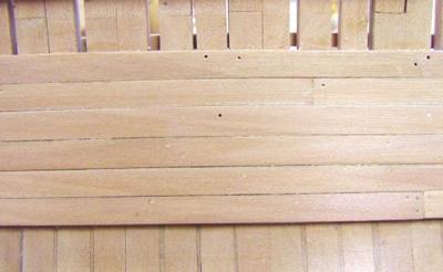
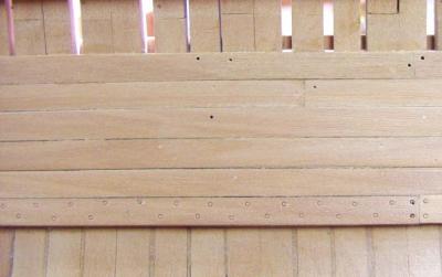
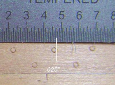


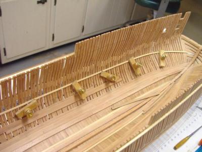
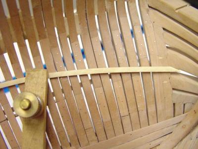
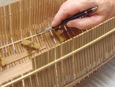
-
1:60 HMS Naiad 1797 Part 28 – Floor Head Thickstuff Posted 12/2/10 Thickstuff was heavy internal planking put over the chocked joints between frame timbers. The lowest level of this, over the floor heads, consisted of six strakes in ships of Naiad’s class – Fifth Rates. This was a departure from the five-strake configuration more commonly seen. Again the 1808 planking expansion shows this special case, which David White also points out in his Model shipwright series on wooden ship building and shows in his sections of Diana in the AOS book. In the picture below two planks of the middle two strakes, each 5 ½ inches thick by 12 inches wide are being glued into place, held in position with pins. The planking expansion provides lengths and butt locations and the model follows this arrangement. In the next picture, one strake of footwaling is being glued adjacent to the outer limber strake. As mentioned in the previous part, this plank will cover the lower futtock chock joints, where they were visible, since these chocks were not necessarily of the correct length. This one strake of footwaling is 3 inches thick and is Castello, a tropical wood similar (and not so similar) to European boxwood. The wet area is from washing off the excess Titebond. In the next picture two curved timbers at the bow are being held in place to dry after boiling and bending to shape. The lower piece is one of the middle strakes of thickstuff. The upper piece is the forward section of the Orlop clamp. Again the length and thickness of these timbers are right off the planking expansion. Even though Fifth Rates did not have an orlop deck, the planking draft uses this terminology. Frigates of this class had three separate platforms over the hold as an orlop substitute. (Note: Further research indicates that although labeled “orlop clamp” on the planking expansion, this strake does not follow the level of the forward or aft platform beams and only supports the middle platform, so this piece would later be removed. I will discuss this further in the next part.) The next picture shows two forward strakes of curved thickstuff clamped for drying and also another plank pinned and clamped for gluing. To keep this work progressing, a lot of tasks are done in parallel to minimize idle time waiting for glue or boiled planks to dry. The next picture, a different view of the above, shows work progressing on both sides. In this picture the dark painted sides of some of the planks can be seen. As mentioned before, these were painted, before ripping into planks, with undiluted raw umber gouache to help accentuate the joints. The next picture is a view from above which shows five strakes partially installed on the port side and three in progress on the starboard side. The one strake of footwaling has been intalled on both sides in the midship area in this picture. The next picture is a closeup, which shows the dark joints pretty well. At this stage some leveling of the planks has been done with a sanding stick and a flat file with a bent handle. At this stage some leveling of the planks has been done with a sanding stick and a flat file with a bent handle. The difference in thickness (1/2 inch) of the two middle strakes can be seen here. The holes left over from the pinning will be filled with treenails later. The curvature in this picture is lens distortion. The number of thickstuff strakes reduces from six to four at the ends. In this picture the top of the port band is complete. The next strake up would be footwaling, but this will not be modeled. There is one more section of lower strake to be added. The footwaling adjacent to the limber strakes has yet to be taken completely forward. A pencil line showing the line of the orlop beams can be seen in the upper right corner. Here are a couple pictures of the completed lower thickstuff, taken midway in the sanding process. The last piture shows how these planks converge at the stern. Some minor paring is still needed on some of these planks. The next task will be to do the treenails – 16 strakes, two nails for each of the say 110 frames, roughly 3500 nails. Down here in the hold I plan to use a mixture of real tree nails and nails embossed with a piece of syringe. The syringe method seems to work quite well – yielding a very realistic, if fake, treenail head. To alleviate the tedium of the treenailing work I will also begin on the upper band of thickstuff and the orlop clamps, which are very close neighbors – and perhaps the crutches and hooks. Lots of options at this point. Ed

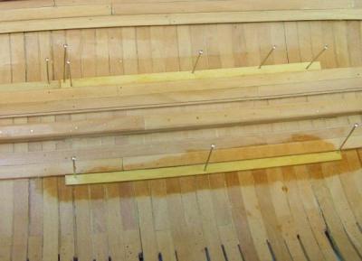

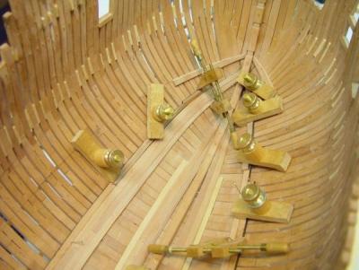
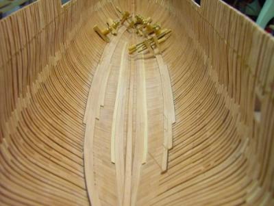
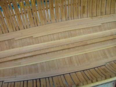
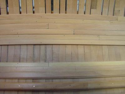
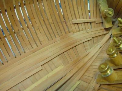


-
1:60 HMS Naiad 1797 Part 27 – Limber Strakes Posted 11/29/10 The limber strakes are the bands of internal planking closest to the keelson. They are thick structural members that run for most of the length of the ship, terminating in the vicinity of the first breast hook forward and the first crutch aft. They are separated from the keelson by a gutter to allow water to run to the well at midship. This gutter on Naiad was 10” wide diminishing to 5” near the ends and was covered with 3 inch thick removable boards to allow clean out. Sizing these members presented an issue of choice between two available sources of information – each providing slightly different data. The first was the Shipbuilder Repository of 1788 and the other was a planking expansion draft dated 1808, labeled “Diana.” After some consideration, I decided to go with the Diana expansion drawing where there was a conflict. This type of drawing was not commonly done and there is some mystery about its date and the Diana label. Using this as a planking reference has the advantage that it shows not only all the thicknesses, inside and out, but also the configuration of the planks, including lengths, narrowing, butt locations, stealers, etc. I obtained this drawing from David Gardiner’s The Heavy Frigate. Based on this, the two limber strakes were both 6 inches thick. The fist was 13 inches wide and the second 12 inches. The first strake has a rabbet cut on its top inside face to hold the removable limber boards. One way of cutting this is shown below. I actually cut this rabbet into the top corner of a wider piece with a thickness equal to the width of the plank, then sliced off each 6 inch plank off on the circular saw – then cut the next rabbet. This makes handling the piece on the mill a little easier and safer. The piece should always be fed into the cutter against the rotation, not with the rotation. In this case the correct direction is to the right. I find the top speed of the milling machine a little slow for this kind of work and there was some grain tear out. Maybe my cutter is a little dull, but I am looking at using the higher speed Dremel tool as a router for future work of this type. The picture below shows the most forward piece of the second strake held in place after steaming. Before boiling this plank the forward inside edge was tapered in two dimensions to fit against he keelson and mate up to the first strake. It was then boiled for several minutes and quickly clamped in place to dry overnight. The final tapering of the outside edge was done later. The bow in the horizontal pine boards provide the pressure to keep the plank in place. This was another good use of the clamps discussed earlier. The next picture shows another view of this and also a piece of straight plank of the first strake being glued into place. In this case, straight pins are used to hold the plank down and in position for gluing. Holes slightly smaller than the pins are drilled through into the floor frames and the pins then hammered in – without bending, if possible. If bending is a problem, the pins can simply be clipped off to a shorter length at a sharp angle. The small wood block is a 10 inch spacer. This picture shows another approach using clamps to pull the plank tight to its neighbor. Combinations of these various methods were used. The wet spots are from washing off the excess glue. Here are some additional pictures of this work in progress. In this picture a 5 inch spacer is being used to set the gutter width toward the fore end. The Repository and the planking draft specify where this width is reached. In this picture another boiled plank is being bent. The darker color of the boiled plank will return to normal when dry. The following are some pictures of the completed limber boards – but before treenails. After gluing, the tops of the planks were leveled off with a flat file with a bent handle and sanding blocks – taking care to not round over the top corners – especially on the rabbets. Below is another one of those “too close for comfort” close up photos. In this picture the four additional smaller bolts in the scarfe joint can be seen. A little paring of the side of this scarfe was done later (after seeing this picture) to make it flush. These two planks leave the joints of the large chock between some of lower futtocks exposed. Since these chocks are not necessarily the historically correct length, I may cover this with one strake of footwaling, the thinner planks that would be next in line going up the side. The dark joints between the planks were achieved by a method I have not used before, but am trying out first down here in the hold. Plank stock was first brought to the thickness of the plank width on the thickness sander. One face was then coated with undiluted raw umber acrylic designers gouache – from a tube. When dry, the planks were sliced off on the circular saw, leaving one edge with the paint. Dark Titebond glue was applied to this edge and the plank bottom. The result is a somewhat more pronounced dark line than with just dark glue. The acrylic gouache also withstands the boiling. All these planks still need to be treenailed.. A few treenails have been installed, but there are a lot more to do. I am still deciding how to handle this down here in the hold. Many of these may be embossed with a piece of sharpened syringe, with enough real nails to provide joint strength. We’ll see. The next step will be to install the lowest bands of thickstuff over the floor heads. This will require at least marking out some of the deck clamps because the thickstuff diverges from the floor and first futtock heads fore and aft to come in fair between the limber strakes and the orlop clamps. The line of the orlop clamps can be seen sketched out in one of the above pictures. We’re just a few days behind the actual progress at this point. Cheers, Ed
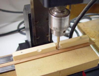
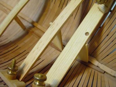
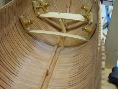
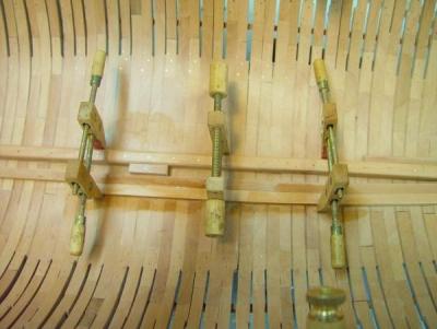
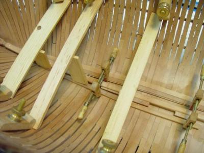
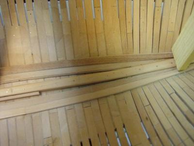
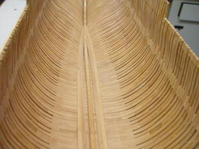

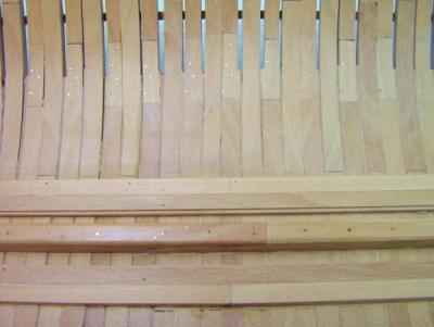
-
1:60 HMS Naiad 1797 Part 26 –Keelson Installation Posted 11/24/10 In the first picture below the first part of the keelson is being glued into place. Necessity is always the mother of invention when it comes to clamping model ship parts together. Here an unexpected use for the gantry and the two clamped squares has been found as a keelson clamping combination. First, a cross bar was clamped to the two squares forming another gantry type device. Then 1/8 inch spacers were put under these on the building board and the two vertical pieces were firmly clamped to the cross bars. When the spacers were removed the knobs could be used to tighten down on the keelson. Here’s another picture of this. And another. Only moderate clamping pressure was needed here, just enough to keep the surfaces in contact. Before starting to fit all these pieces up for assembly a few minor high spots needed to be removed from the centers of the floor. This was done by sanding. Once all this was done the inside of the hull was sanded from the center up to the heights of breadth. The first step was to remove all the cross grain scatches with 120 grit paper - with the grain – a tiresome task. Then a triangular detail sander with 220 paper, then 320 paper was used. To roughly match the inside curvature the detail sander was fitted with a shaped piece of Homosote held in place with two faced carpet tape with the paper held on the same way. This sanding was followed by 000 then 0000 steel wool, and finally Scotchbrite white grade. These last steps will have to be repeated when the keelson and all its bolts are installed. Washing off the Titebond will leave a film and final sanding of the keelson bolts will leave some scratches. In the next picture the stemson is being held in place after gluing – again with the aid of the gantry. The last piece to be installed was at midship, because here the keelson scarfes reverse direction, so that piece has both its joint faces facing down. In the next picture the aft part of the keelson has been bolted and had some polishing. There’s more to be done on the lower futtocks, but some of this will be covered by the limber strakes. The bolting process is the same as was used on the futtock joints described in a previous part – predrilled slightly oversize holes, wire with medium CA inserted in and out to distribute the CA, ends clipped off, washed with acetone and filed off. These bolts, however, were a lot longer – approaching ¾” – roughly four feet. Also, an additional four smaller bolts were put through each scarfed joint. And the bow. The last picture shows the finished keelson installed. The next task will be to make and install the limber strakes and this will be covered in the next part. The build log is now just about a week behind actual construction, so the reports may be coming a bit slower. Stay tuned. Ed

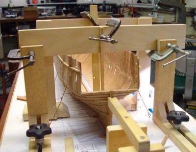
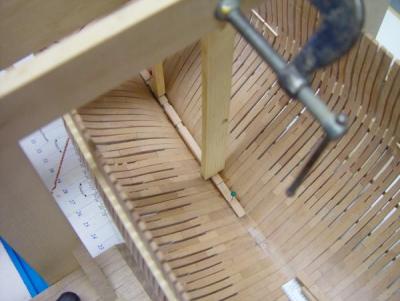


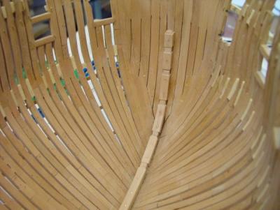

-
1:60 HMS Naiad 1797 Part 25 –Keelson Fabrication The next step was to make and install the keelson, the stemson and the sternson knee. The keelson is 1’3” square with the top corners chamfered off. I did not score the keelson down on the floor timbers, nor did I notch the rising wood for these. This is a lot of work, especially with the irregular timber spacing and is totally invisible once everything is assembled. Below is a picture of the pieces after the scarfed joints were cut. These scarfes were 4’ 9” long. They were cut in exactly the same way as described for the ribband joints, but with larger tools. Before cutting the joints each piece was carefully fit to the floor centers. Only some minor leveling was needed for these to lay flat. You will note in the above picture that the center piece has both its scarfes cut from the bottom as do the two end knees, so these were the last to be made. Once the first piece was cut to length and the two scarfes cut on its upper face the adjoining joints were matched and those pieces cut to length – and so on. The curved pieces at both ends were cut from patterns and trimmed to fit flush with the tops of their respective deadwood. The two knees were made earlier so it only remained to cut their joints. The top chamfer was put on with a file. Here the sternson knee has been pinned in place, the last piece to be made. In the next picture the stemson is temporarily in place at the opposite end. With all the pieces made and fit into place, the dadoes had to be cut where crutches, breast hooks and deck hooks would be fit later. All these pieces were roughed out at this time to aid in cutting the keelson dadoes. Before going through the steps, here is a picture of these pieces temporarily assembled after they had been roughed out and the joints in the forward keelson pieces cut. This picture shows the four breast hooks and the breast hook for the lower deck. This last piece is Castello, a tropical variety similar to boxwood, which I am considering using for the deck framing. Because this piece is rounded up to match the lower deck round up, it has been sized to thickness in its center by cutting back the bottom and chamfering the top at the extreme ends, but it has not had the rounded up shape formed completely. This will be done later when the deck clamps are being fitted. The upper deck hook, not shown here, was also roughed out in this way. Both these deck hooks fay directly to the cant frames and hawse timbers. The others fay over the internal planking and so those faces will have to be refined when the planks are in later. It was much easier to match the forward faces of the hooks to the framing without the keelson pieces in the way. This was done without patterns. Pieces of the right thickness were cut and the mating face eyed up and cut out on the scroll saw. The curved shape and the bevels were then refined on the disk sander, then by hand until there was a good match with the frames. The pieces were then notched where they will fit the keelson and their back faces cut to a rough curve. A lot of wood will be removed from the backs of the deck hooks and the others but at this stage the main thing was to get the forward shape and the right overall length. The deck hooks will mate up to ekeing pieces on either side, which will in turn fay to the first deck beam, but it is way to early to be dealing with that. All these hooks can all be refined later when they are installed. In the meantime they will go into storage. After these hooks were shaped and notched to fit the keelson, the joints on the keelson pieces were cut. These were all cut by hand using a razor saw, small chisels and a small file for finishing. The following pictures show how these were cut. The keelson pieces have dado slots on the sides and top to receive the hook or crutch. After marking out, cuts were made on one side for the sides of the dado. The distance between these cuts was taken from the thickness of the piece to be mated up. The dado was then pared out with a 1/8 inch paring chisel. With one face cut both the top and bottom sides of the dado were marked out. The purpose of these marks on the bottom, which has no cut, was to assure the same angle for the dadoes on both sides. With marks on the top and bottom, the correct lines could be drawn on the side. The dado on the top and the other side were then cut. Below is a picture of the three crutches on the aft part of the keelson. The next picture shows the finished dadoes on the stemson and first keelson piece without the hooks. With all this work done at both ends the lower framing could be sanded and polished up, and the keelson could be permanently installed. The final installation of the keelson will be covered in the next part. Ed