EdT
-
Posts
2,214 -
Joined
-
Last visited
Content Type
Profiles
Forums
Gallery
Events
Everything posted by EdT
-
Hi Gary, Great to see you back. I'm sure I'm not the only one who has been missing your work on Alfred, but it just hasn't been the same here on MSW without it. Good luck with the reconstruction. Ed
-
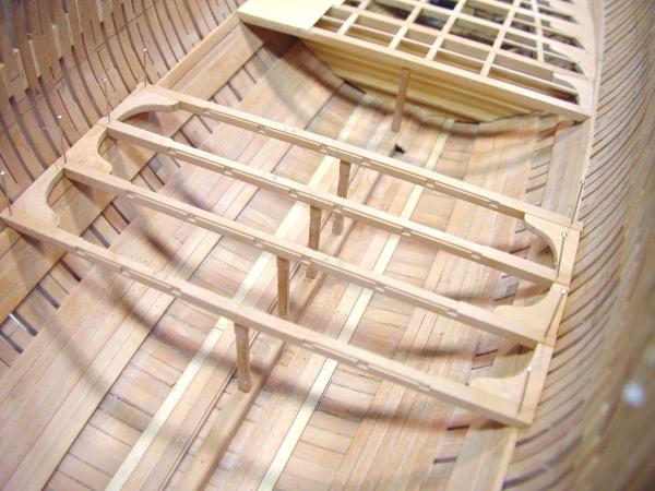
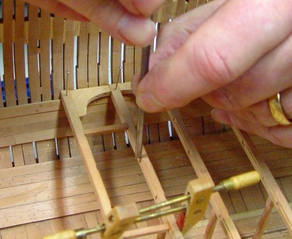
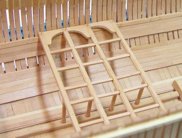
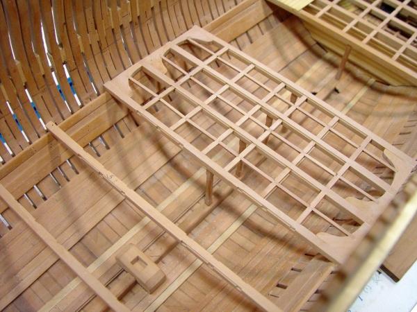
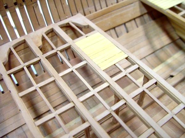
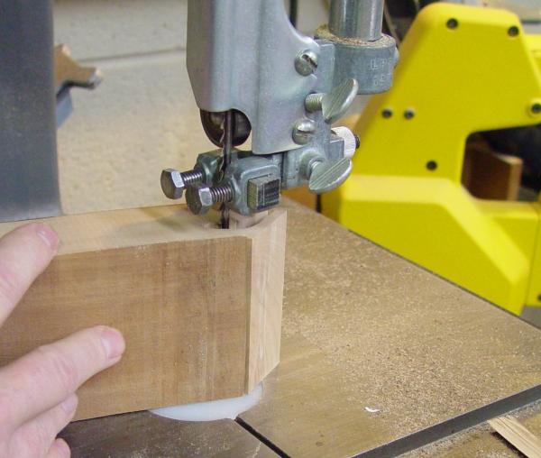
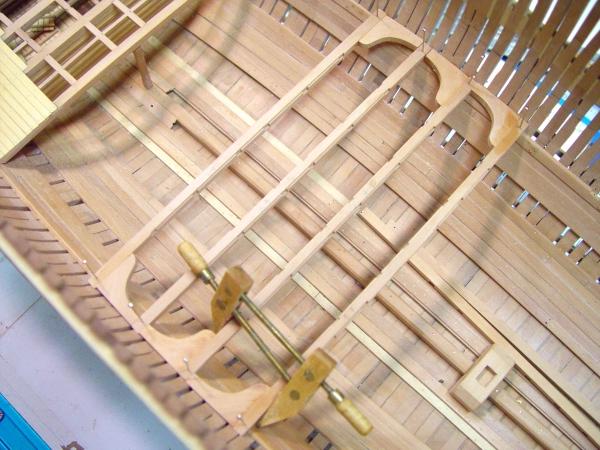
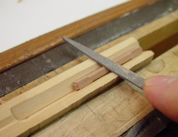
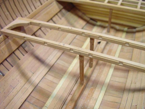
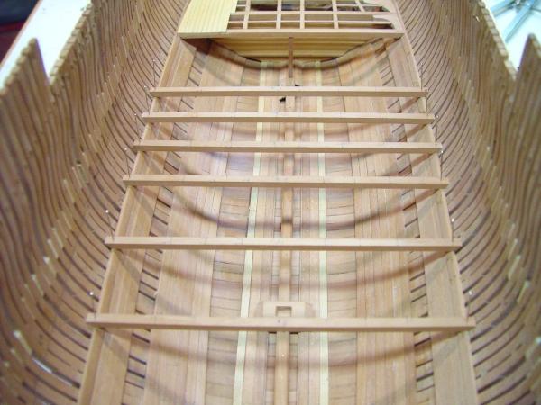
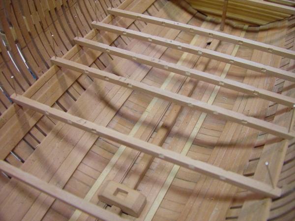
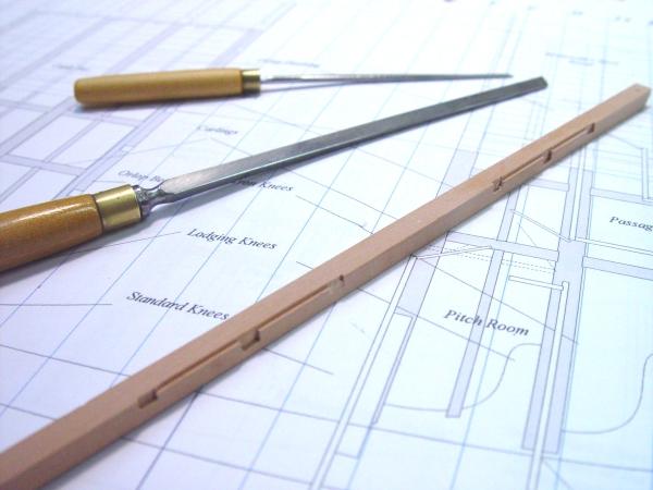
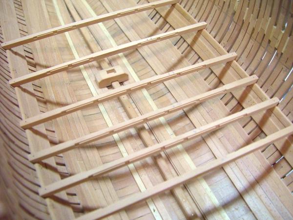
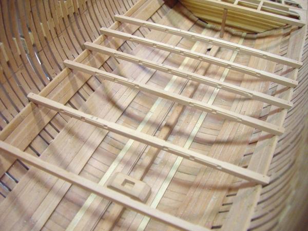
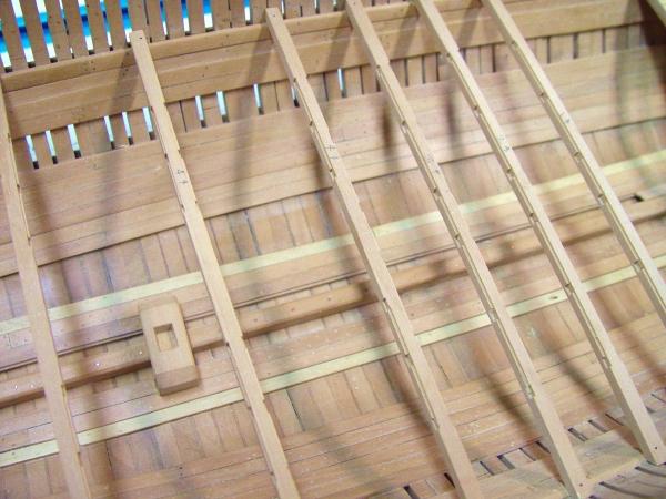
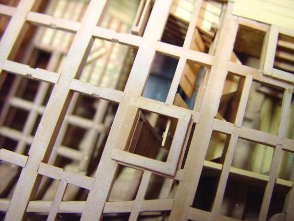
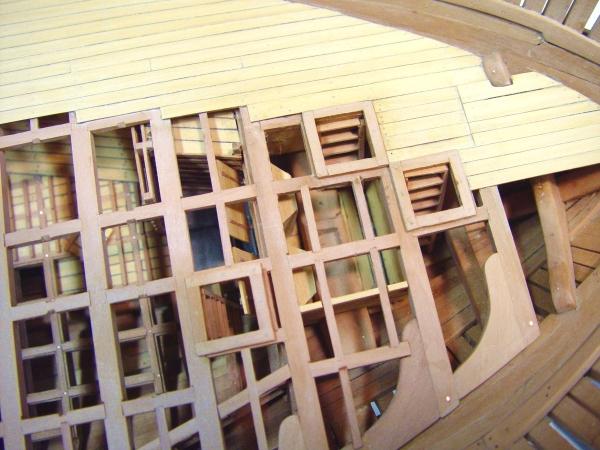
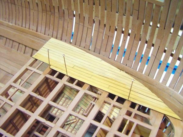
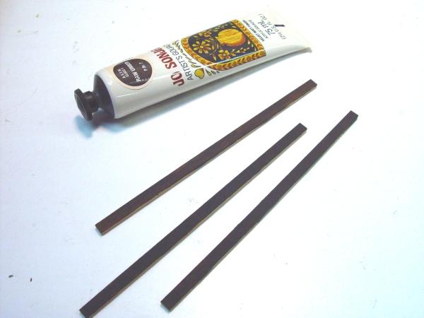
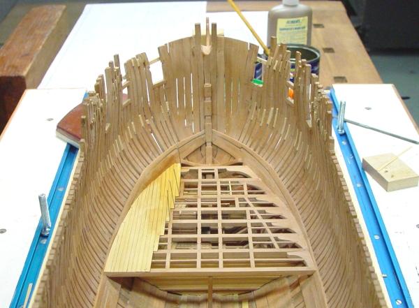
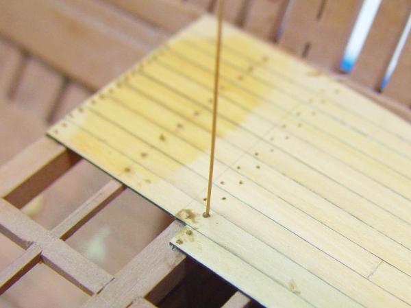
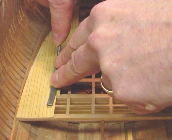
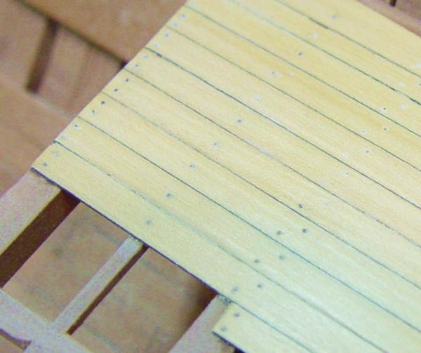
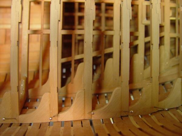
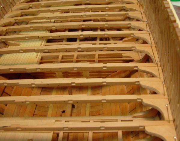
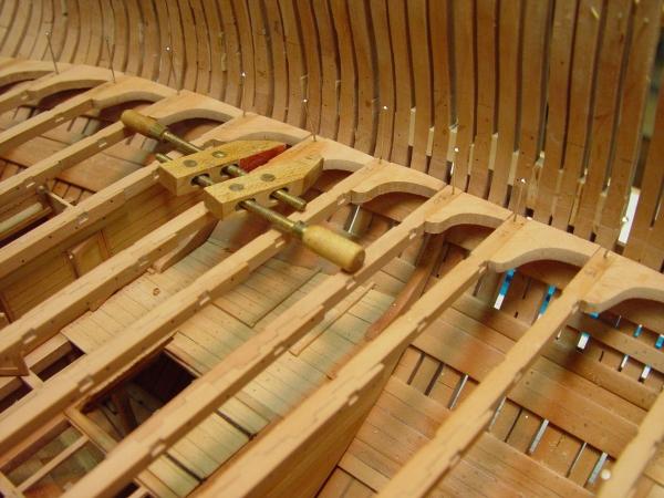
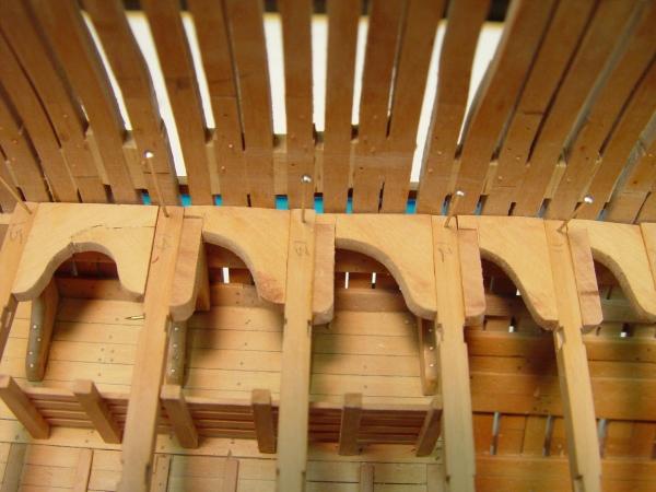
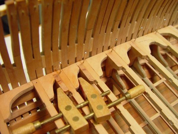
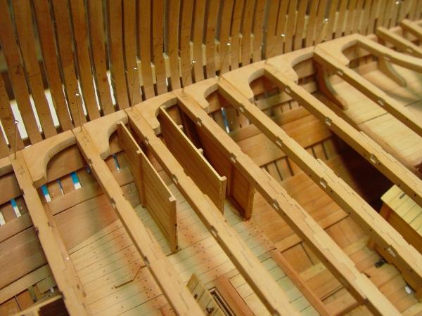
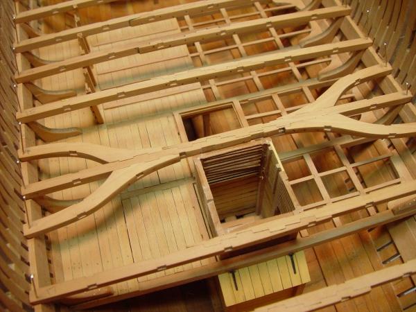
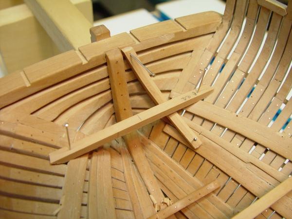
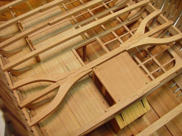
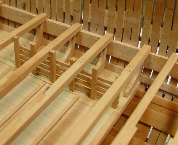
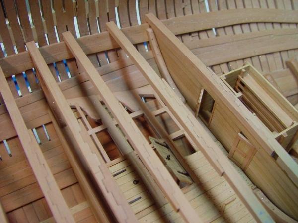
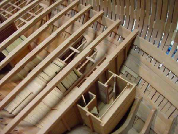
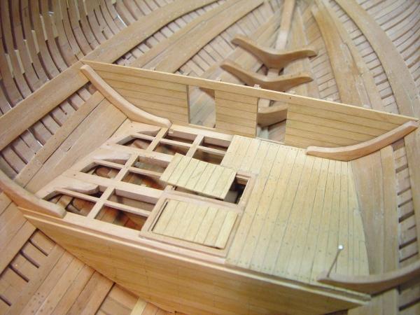
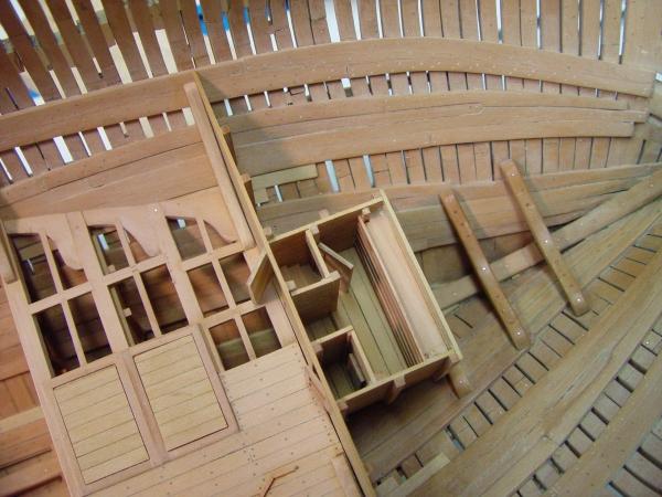
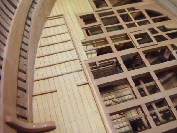
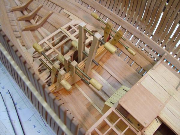
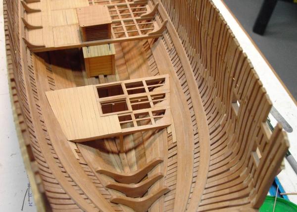
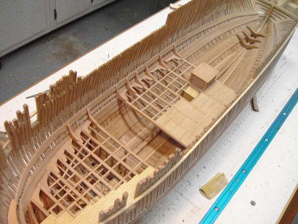
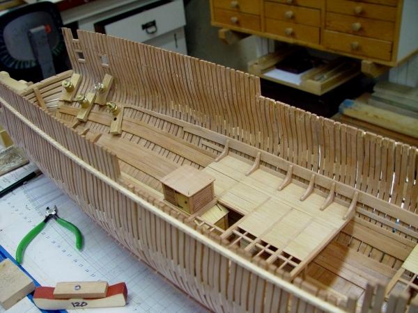
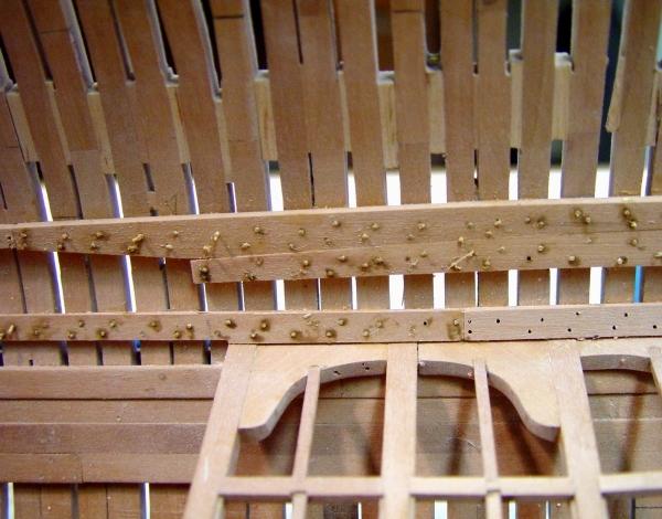
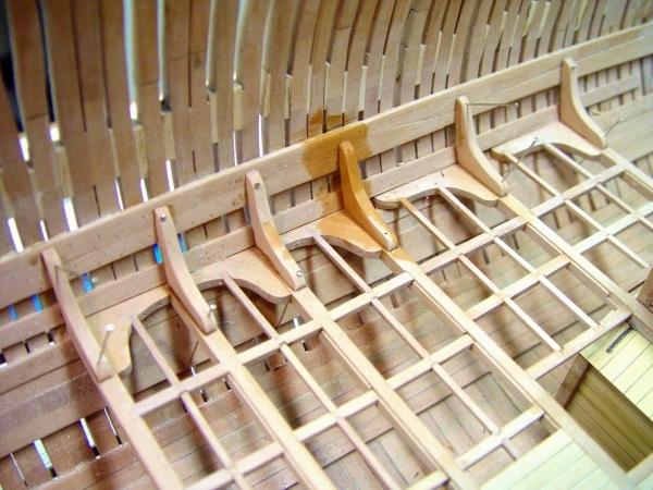
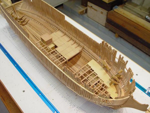
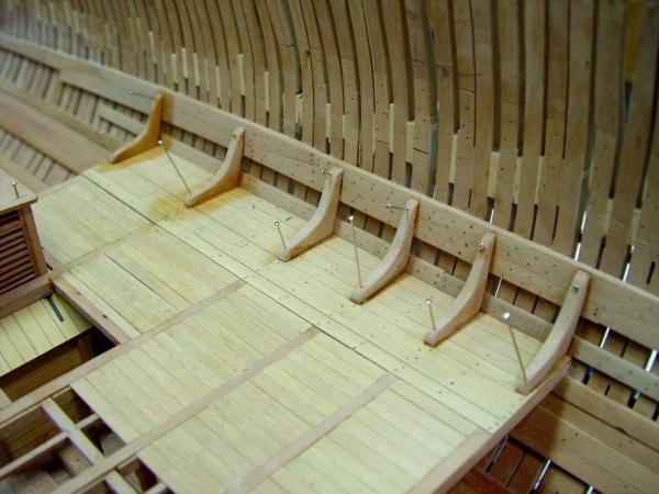
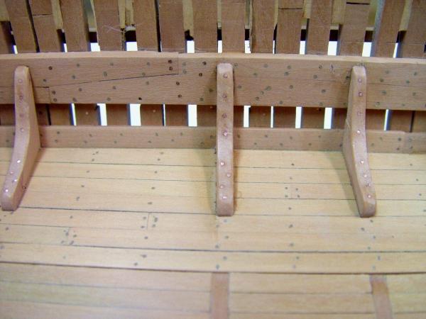
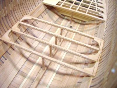
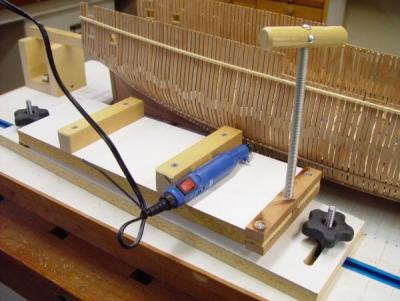
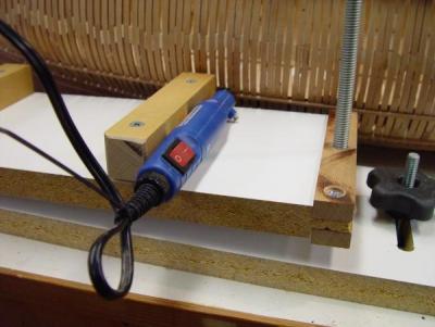
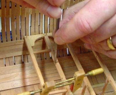
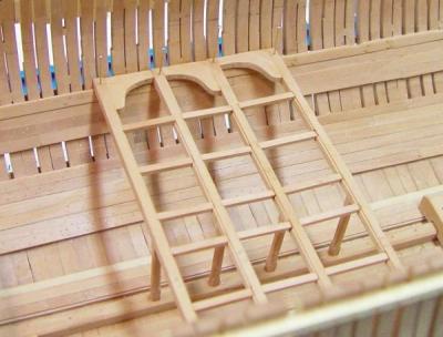
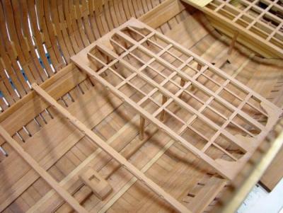
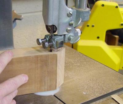
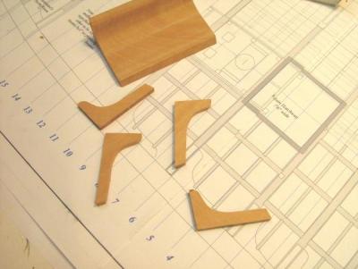
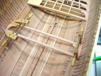
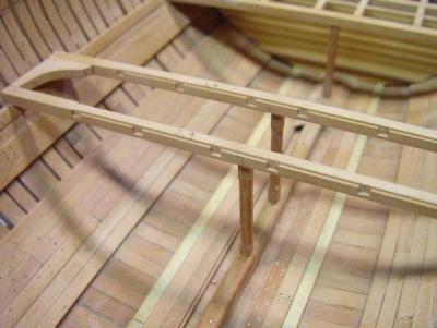
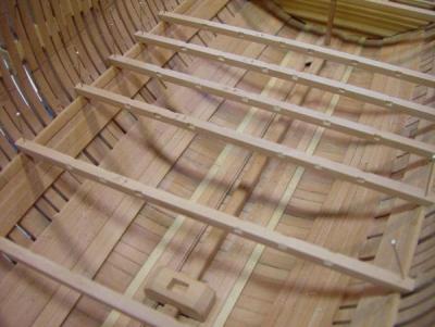
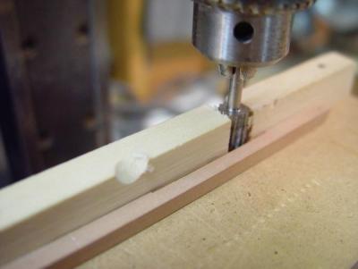
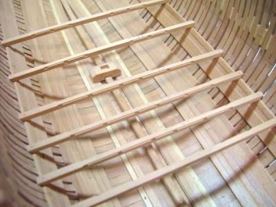
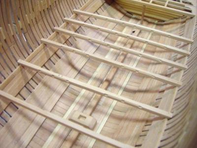
1:60 HMS Naiad 1797 Part 60 – Lower Deck Knees 1 Posted 3/25/11 With the complexities and controversies of the mainmast partners now consigned to the past - until they arise again on the upper deck, or maybe even with the lower deck foremast partners – it was time to move on the lower deck knees. The knees were extremely important to the structure of the ship. Their purpose was to form moment connections between the beam, the frames and the sandwich of clamps and outer planking that are the primary longitudinal members.. There are two knees at each end of each beam. a horizontal lodging knee to maintain the spacing between the beams and reduce flexing in the horizontal plane, and a vertical hanging knee to resist bending at the beam end in the vertical direction. They were primary timbers in maintaining the rigidity of the hull – much like gusset plates make steel building structures rigid. The lodging knees are 8” thick, the hangers 8 ½ inches. Both bolt through the sides of the beam and in and out through the hull frames and planking. The first picture shows some lodging some of Naiad’s lodging knees from above. These have been glued to the side of their beams, which are still only pinned in place. The beams will be removed to install bolts and for further steps associated with the hanging knees. In the next picture all the lodging knees, except a few around the beam arms, have been glued to their beams. As described earlier, the knee profile was first cut out on a 3-inch wide piece of pear on the band saw. Individual knees were then sliced off that piece as needed – like a loaf of oddly shaped bread. This eliminates intricate cutting of each knee, establishes the right grain direction, assures they are all roughly consistent in shape and saves a lot of time. The next picture just shows one of these knees clamped for gluing. The next picture shows the first few hanging knees attached to the side of the beams opposite the lodging knees. To get these up against the deck clamps each lodging knee had to be notched back to the face of the clamp. To do this a strip of wood the thickness of the hanging knee was used to mark the cut line on each of the hanging knees. The beam to receive the hanger was then removed so the line of the clamp could be marked. The beam with the lodging knees was then removed so it could be clamped in a vise to cut out the notch with a razor saw. The hanging knees need to fit tightly in the notch, against the side planking and of course against the side of the beam. At the end of this step each beam will have both of its knees attached. It can then be removed to have fore and aft bolts inserted through both knees and the beam. These will be iron bolts. When the beams get permanently installed, holes will be drilled through the frames from the outside and copper bolts inserted, but there are several other steps before the beams can be installed permanently. One of those steps is the installation of partitions on the port side of the ship, which will be decked. Some of that has been done concurrently with the knees. The next picture shows partitions between the steward’s room, the slops room and the marines clothing room. The latter two are really just walk-in closets. Notches in these partitions for the carlings will have to be cut out in place. Notches for the knees were cut before installing. The hatch over the spirits room is also getting new covers of the double flap variety, which is more correct. There may be more work yet to do with these two hatches on the aft platform. Construction is starting to overtake the drafting, so some time had to be taken to get that caught up. This involved finishing drawing of the mizzen step, the foremast partners, and the lower deck hatchways, and making sure all this was going to fit properly with the orlop deck arrangements. This took some research and some time. There are a variety of things going on right now and that keeps the work interesting. The knees are progressing much faster than I expected. Ed
-
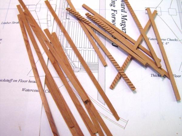
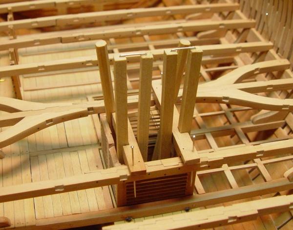
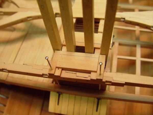
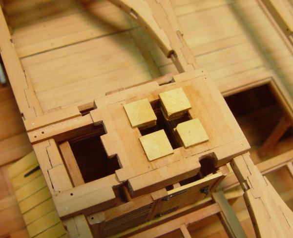
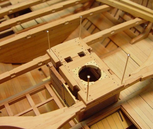
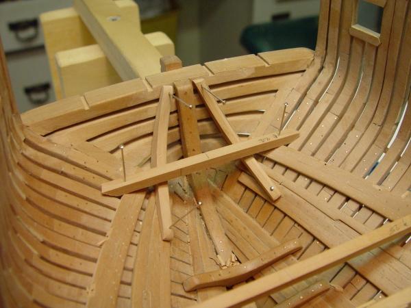
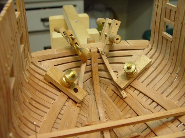
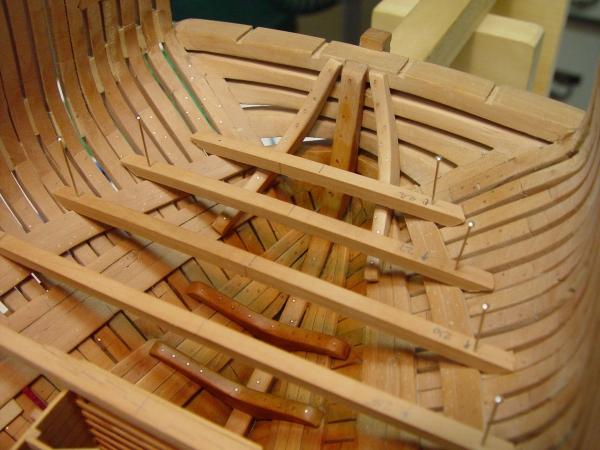
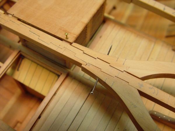
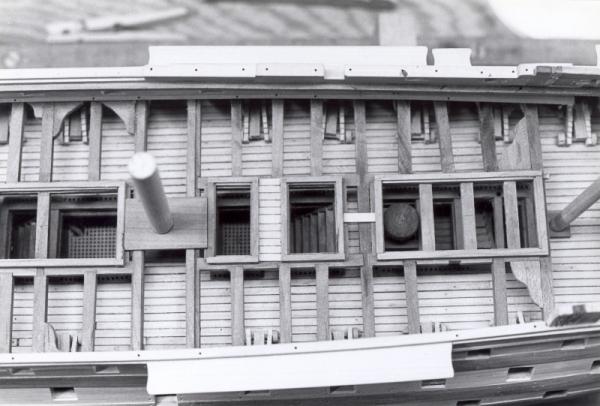
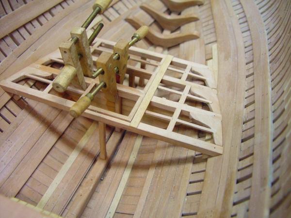
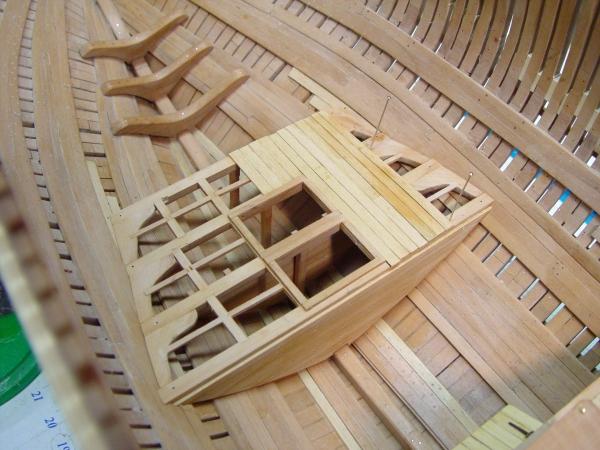
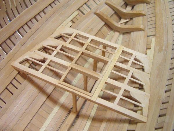
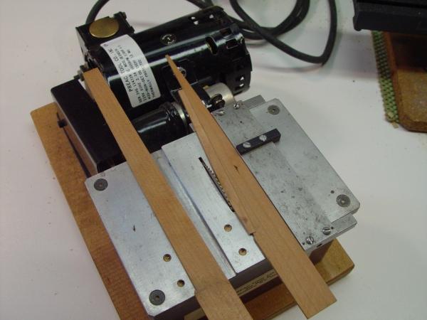
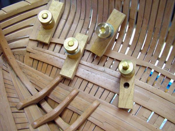
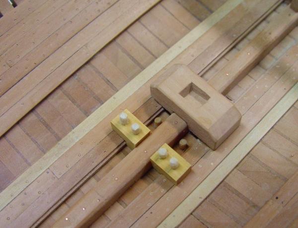
1:60 HMS Naiad 1797 Part 59 – Lower Deck Main Partners Posted 3/22/11 It may seem like I’m putting off the big knees job, but in order to finish cutting the carling seats for the beams, I had to address the mast partners, since the carlings for these do not match the others either in size or location. They are much larger and their location depends on mast diameter. This issue is complicated by another problem and that is the need to have 6 straight pump casings make their way from their bases in the well to the right spot on the upper deck. Those who have been following this series will have noted the difficulties discussed in several posts in the last few days. The picture below illustrates the problem with the pumps. The four shafts in the foreground are the 10 ½” square casings for the Cole Chain pumps. There are two pumps and at the bottom these shafts connect to an intake housing between the keelson and the second limber strake – no room for maneuver there. The upper ends of these come through the bottom of a cistern on the upper deck where the water is collected and discharged. The centers of the tops need to be 24 inches apart precisely, because the sprocket that drives the chain is of that diameter – no latitude here. The bent pins holding the tops together are maintaining this 24-inch distance at the top. These shafts must pass on either side of the lower deck mast partner carlings and given the geometry just described, there is a fixed distance between these at the level of the lower deck and it is much smaller than the width of the carlings, so they have to be cut – no way around this regardless of layout. The two octagonal shafts forward are for the two elm tree pumps – same problem. They are as far out as they can go in this picture without enlarging the well and its width is well defined by the location of the limber strakes (no pun intended). It took some advice from our MSW experts, multiple readings in Steel and others sources, and some head scratching to get this drawn up and built. The following pictures show the progress of its construction. The two fore and aft carlings are 15 inches wide and 14 inches deep. They fit into vertical slots in the beams and have a 6 inch lap over the full width of both beams with two bolts driven through the beam vertically at each end. All this restrains lateral movement of the mast. These carlings are connected by 6 inch thick cross chocks, which I have installed in the athwartship orientation. They have 3-inch laps which rest on 3-inch rabbets in the carlings and are bolted with four bolts to each. This is quite a massive rigid structure. In the picture above, the cross chocks are being marked so they can be cut to fit around the casings. Pins through the carling boltholes are keeping this all together. The next picture shows the rough cutouts in the cross chocks and also the rabbeting of the four corners of the mast opening to take four corner chocks. All cross chocks are glued in at this stage except for the two to the left. They will be glued in much later when the shafts are permanently fixed. In the next picture rough corner chock blocks have been glued in. These were done in Castello so their shape doesn’t get obscured. Their grain runs tangential to the curvature of the mast. In the next picture the corner chocks have been opened up to take the mast wedges, leveled off with the top of the cross chocks, and have had their four bolts each installed. All the other bolts are also installed in this picture. The last picture shows the assembly with the pump shafts fitted up temporarily. The top of the well structure has been finished off with some upper framing. The partners are not fastened permanently yet. There is still a lot to do on the deck beams before that happens. Ed


-
Thank you for the comments - much appreciated as always. I appreciate the comments on the reposting, because it is taking some time. I am trying to post five or more parts each day. I am looking forward to getting finished with the reposts so we can get back to current progress. As far as that is concerned, the model is approaching completion. Perhaps another month. Most of what is left now is ironwork. Your patience is appreciated. Neill, I'm always glad to hear of interest in the book and I hope you will find it useful. I believe you will. Martin, I plan to include images on the disk where color will be of value to the building, perhaps some others. I believe there will be a color section in the book. Hakan, thanks. I know you have been with me on this from the beginning and I appreciate that. I am sorry that your many questions and comments to the original posts have been lost. Ed
-
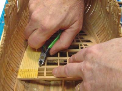
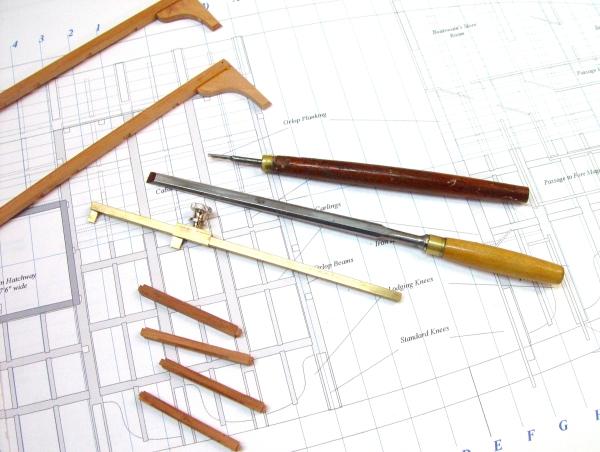
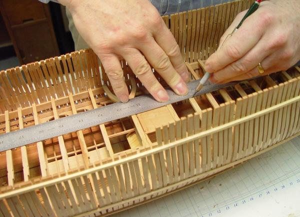
1:60 HMS Naiad 1797 Part 58 – Deck Beam Joinery Posted 3/20/11 After getting the chisels sharpened the locations of all the seats for the carlings were marked on the beams while they were pinned in position as shown in the first picture, except for the mast partners. Those were still on the drawing board. After the beams were marked in pencil they were removed one-by-one, had the pencil marks nicked with a sharp knife, had the lower face of the seat lined out with the compass shown to the right and then were cut as shown in the next picture. This picture shows the first plunge cut into the side of the beam being made with a small chisel. Two of these cuts define the sides of the seat. The next picture shows the paring cuts being made after both sides of the seat were cut as shown above. These cuts very shallow, made with very little pressure and the shavings are ejected when the cut reaches the side cut. The joints were then cleaned up with the small chisel to the right. This process, cutting the twelve seats in each beam, takes about ten minutes per beam by this process. In the next picture all of these have been cut and the beams pinned back in position. In this picture the iron bolts, six per scarf, have also been installed in the twenty scarfed beams. These were 1” square bolts on the real ship. Here they are 30 lb black monofilament fishing line, which is the size of the 1.5-inch bolt heads. The bolts are held in with CA. In the next picture the beam arms are being glued to the beam which will rest at the aft end of the main hatch and just forward of the main mast. In this picture the small clamps are providing the high pressure and their big brothers only very light pressure. The next picture shows this assembly fit into place after its bolts were installed and it was cleaned up a bit with 220 paper and 0000 steel wool. All the beams were given this surfacing step and then pinned in place for the next step – the installation of the knees. The last picture shows a close up of the beam arms joints, which like the beam scarfes, were cut on the milling machine. In this picture the mortises in the beam sides for the two large main mast partners have been cut after quite a bit of head scratching on what this configuration should look like and also how to fit the pump casings around these timbers and keep them out of the way of each other. The partner carling will fit into these large vertical slots, which in the picture, are just above the louvers in the well - which in spite of all my protective measures, are still acting up and shifting out of place. These large partner carlings will have a half lap that rests on the top of the beam, extending all the way to the other side. These will then be bolted through the beam from above. A section through the pumps can be seem in a posting above this one, although the drawing has changed quite a bit since that version. Next come the hanging and lodging knees. Ed


-
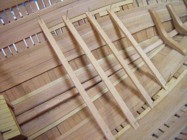
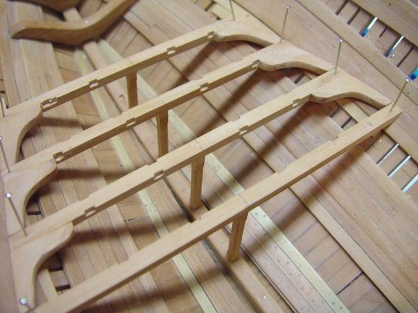
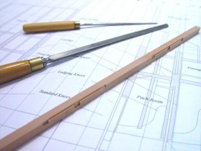
1:60 HMS Naiad 1797 Part 57 – Sleepers and Lower Deck Beam Arms Posted 3/16/11 With all of the lower deck beams fitted and pinned into place there were a few tasks to be done before going to work on the knees and the final beam installation. The first of these was to install the first two of the four sleepers, one on each side of the sternson knee. In the picture below one of these is being fit into place so that it runs underneath the last lower deck beam. The purpose of these members was to give further strength to the structure of transoms and fashion pieces. Their precise locations are not well documented. On larger ships the center ones fay onto the sternson knee and terminate lower. On frigates they all reach the top of the wing transom. I had to make some decisions on how to fit them around this last beam. I expect the outer two to go over the ends of the beam, which will be cut back to its seats on the clamp to accommodate them. In the next picture both of these are ready to be glued into place. These are very odd shaped pieces and it took some time to get them to lay flat on the planking and the transoms - and to look symmetrical. In the next picture these have been glued into place and held with the usual clamps. With the work below the second band of thickstuff in this area now complete a first coat of turpentine/beeswax was put on just before the next picture was taken. It will dry much lighter and less orange. In this picture the sleeper bolts, 11 in each, have been installed through to the outside of the frames and finished off on the inside. Some of these are shown coming through the transoms and aft cant frames in the next picture. They still need to be filed off flush on the outside. The next picture shows the beam arms for the beam at the main hatch loosely fit up for marking of the carling seats. The tabled scarf joints were cut on the milling machine using the same process described previously, except these could be cut in a horizontal position. The arms were machined first, then fit up to the beam so their locations could be marked. Then the beams were machined. The next picture shows a closeup of one side of the beam arm assembly. These joints are loosely pinned for the marking of the carling positions. They will close up nicely when clamped. When this picture was taken the carling positions on all the beams were marked, so there is no way to further avoid cutting all these seats – 180 of them – except some chisel sharpening needs to come first. Cheers. Ed
-
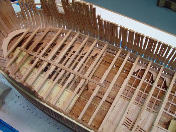
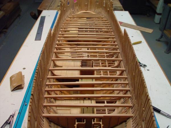
1:60 HMS Naiad 1797 Part 56 – Lower Deck Beams Posted 3/14/11 After completing the fabrication of all the two-piece beams for the lower deck work continued on the details needed to complete the orlop level concurrently with installation of the beams. The picture below shows some detailing of the cable tier, including the dunnage beams, the side stanchions and the battens on those. With the beams set, the heights of the stanchions could be adjusted. In the above picture they are only temporarily positioned. The next picture shows the hinges and eyebolts on the hatches to the spirit room and fish room and also the bolting on the aft platform standard knees. The next picture of the same area shows the lantern in the aft magazine, the last detail to installed to complete that. The picture below shows the progress of installing the deck beams. First they were cut to length and their ends shaped to butt the frames. They were then located and the spots on the clamps marked so these could be let down on the beams. The height of each beam was checked at the center with the gantry and at the ends by measuring down from the top of frames with the length guage. The seats were adjusted accordingly to get the correct levels. In some cases this required some minor trimming on the tops of the clamps so the amount the beams were let down was held to 2 inches. After the beams are all set, they will be pinned in place, the beam arms will be made and fit, the carlings will then be marked and their seats cut. The bolts in the scarfes will then be installed, knees fitted, pillars fitted, etc. The orlop partitions on the decked port side will be installed concurrently with all this. The next picture provides a closer view of the beams being let down on the clamps. Steel says the ends of the beams should be reduced so they are let down 2” on the clamps. His plate however shows seats cut in the clamps. This may be a drafting error. I have seen that detail on another drawing – somewhere. On the model there will be no visible difference, so it’s a bit academic. I cut seats in the clamps 2” deep. It helps to positively locate the beams, which helps with succeeding steps. The next picture shows some of these beam end arrangements. If it were not for the one beam in this picture that is out of position, one could not tell if the beams or the clamps were cut. Frankly, I believe it was poor practice to cut the beams. It effectively reduces the section bearing the load. Whatever. The last picture shows most of the beams set in place. Ed
-
HMS Victory by EdT - FINISHED - 1:96 - POB
EdT replied to EdT's topic in - Build logs for subjects built 1751 - 1800
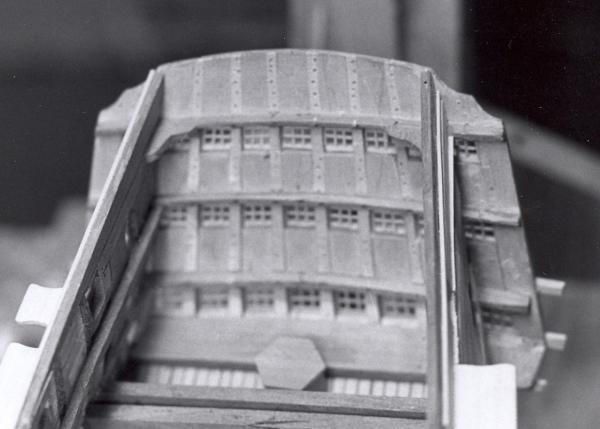
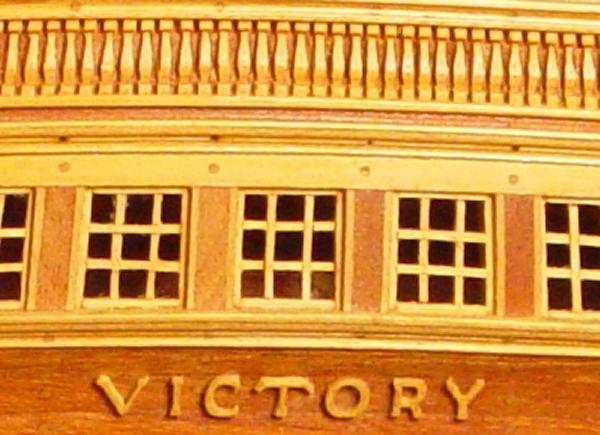
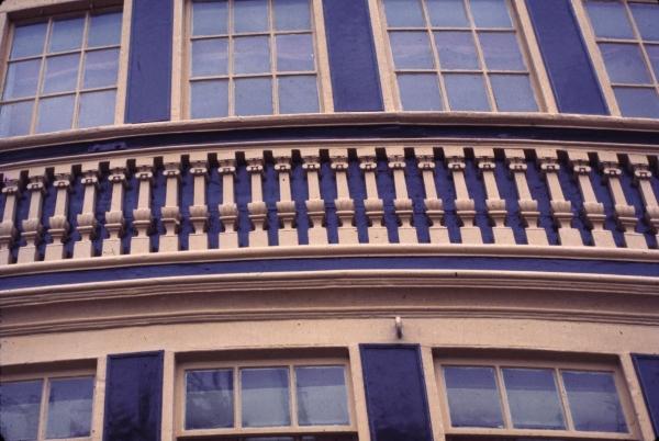
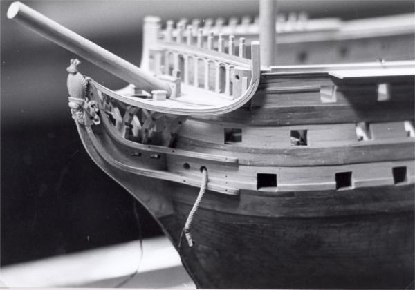
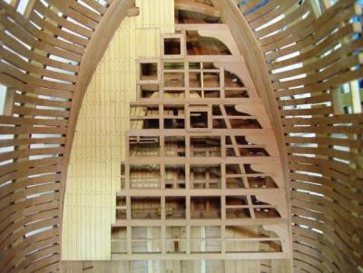
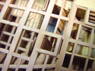
HMS Victory1:96 Scratchbuild Project Part 4 - The Stern Galleries and Lower Decks The progress of the model during the 1980’s is a memory test for me. Although a fair amount of work was done between 1980 and 1986, no pictures were taken. For the next few years, the model was in storage while we were out of the country. However, a lot of work was done in the early 80’s including the construction of the stern, the planking and fitting out of the lower and middle decks, making the guns for those decks and a lot of the topside planking and rails. The Stern Although some planking was done before the stern, the stern with its detailing was done very early because it was almost completely prefabricated on the bench before being installed and neither planking nor the lower decks could be completed without it being in place, so I will start with that part of the work. This picture was taken in 1997, long after the stern was installed. The above picture shows the detail of the stern galleries and the counters, the 27 slanted windows with 9 panes each, the two rows of 69 slanted carved balusters, the carvings, the fluted moldings, etc. The carved boxwood letters of the name were a little extravagance not based on the prototype, but I liked the idea, especially since I wasn’t going to paint. Its one of the few departures I allowed myself. All this detail was done very early so it could be done on the bench on a flat surface with good light. I thought this worked out extremely well and so I will describe the process in some detail. First, of course, the wing transom had to be in position. This was not described previously, but was put on in when the basic framing was done. This timber is curved on its aft face and on its top. The aft curve is quite slight which gives the stern an almost flat appearance. Being higher in the middle, the wing transom sets the pattern for the curve of the counters and the horizontal gallery lines, which parallel the round up of the decks. At the same time the eight “vertical” stern timbers, with their curved feet, slant both inward and markedly aft. All this required some careful patternmaking and measurement during installation. Patterns for the individual stern timbers were developed using techniques described in the MSB version of part 2. They were then cut out in maple and pinned in position across the wing transom. The outer two were actually screwed down temporarily with tiny wood screws. Angles aft and inward plus the aft curvature were measured very carefully using templates that could also hold the timbers temporarily in place. I am sorry I have no pictures of this. Once the timbers were in their correct position, the curved interior deck transoms and the main exterior counter rails were attached permanently to the stern timbers. Then, filling pieces of flat maple were glued between the timbers except for the window openings. This gave the whole assembly rigidity and provided bedding for the exterior planking. The assembly was then removed from the ship and taken to the bench for completion of the detailing. The following picture taken years after permanent installation shows the maple inserts between stern timbers and window openings. It also shows the internal horizontal deck transoms and the external rails which had not yet been trimmed. This picture was taken in 1995 several years after the stern as installed and after completion most of the topside planking. The hexagonal table covering the rudder head and the wide seat of the middle deck ward room are also visible. Once moved to the convenience of the bench, the first step was to finalize the shape of the gallery structure and add the missing panels at the sides. Frequent fittings on the ship were made to assure all this was correctly sized and shaped. When this was done the other horizontal rails and the window lintels were put on in boxwood. Then the remaining exterior planking was put on over the whole gallery surface and below on the two counters. This was done in 3” (1/32”) cherry which was attached with glue and boxwood tree nails. I will describe the making of these tree nails later. Thousands were used on the model. In the above picture the holes for the tree nails can be seen on the inside of the stern timbers. The following picture is a close up illustrating the results of some of the next steps. I did not want to paint the model, but I did want to contrast the woodwork in a way similar to the painted original (except for the lines of the gun ports which I will discuss later). This was done throughout the model using the pale yellow European boxwood on the darker reddish cherry. This contrast shows well in the above picture. After the planking was installed, the columns between the windows were made and installed. This was done as follows. Two thin sheets of boxwood were glued on opposite sides of a cherry core, a strip maybe ½” wide, with the total lamination thickness equaling the width of the columns between the windows. The column facades were then sliced off of this on the circular saw, cut to length and glued to the aft side of the stern timbers, matching their widths. The next step was the dreaded balusters, two rows of 69 each slanting progressively inward, carved square (not turned). The following picture shows how ornate these are on the real Victory. The balusters on my model are about 1/32” square and about ¼” long. I could not hope to duplicate the above patterns at this size, so I decided to retain the square shape but simplify the pattern. The result is proportionately correct, but of course lacks complete detail. To assure uniformity and alignment the balusters were carved after being glued to the façade. Once the were secure, a very sharp knife was used to scribe the lines of the pediments and heads of the columns (top and bottom). Then the aft part of the curved shape was cut with a small chisel across the whole row. This approach assured alignment top and bottom square sections. When the aft faces of the balusters were done, the side shapes were cut with a small chisel and surgical scalpel. Next the 1/64” by 1/32”window frames were installed, a pretty straightforward task. They are inset just below the surface of the column facades and are actually glued to the stern timbers. The window mullions themselves are the same depth and thickness as the frames. To make them, a wide (1”) sheet of boxwood, 1/32” thick, was scored, twice only, with a .015” circular saw blade, 1/64’ deep at the pane width spacing. The mullions were then ripped off in 1/64” slices and assembled by locking the notches together. There was just enough movement in these to slant them to the desired degree. Then they were then trimmed to size, touched with a bit of glue and push fit into the frames. No glass was installed. They have been secure and I have not managed to stick a tool or a finger through a single one of them. The only remaining work to be done was the fluted rails and the carved figures and stacked arms above the top windows. The figures and arms were cutout from a thin sheet of boxwood with a fine toothed jeweler’s saw, glued in place, then relief carved with very small chisels. The ropelike rails were done with a needle file on the edge of a wider piece then ripped off on the saw. The fluted rail may have been done in a similar way using a rotary tool. I cannot remember. The stern galleries were then permanently attached to the wing transom and secured structurally with additional members and knees, completing this major piece of work. The Lower, Middle and Upper Gun Decks The Lower and Middle gun decks would only be visible in the finished model by peering into the gun ports or through hatchways, so I did not want to overdo the detail. The beams for the Lower, Middle and the Upper decks do not attempt to replicate the original. However, the simplified beam structure provided by the frame assemblies needed to be modified and supplemented at every level to accommodate hatches, mast partners, etc. The following picture shows some of the simplified beam structure of the Upper deck and also some of the detailing of the decks below. This picture taken in 1995 shows the middle deck planking and gun carriages plus the simplified planking of the Upper deck. The planking of the lower and middle decks was done in maple, 1/8” wide, with no attempt to replicate plank length or stagger pattern. The dark caulking between planks was simulated by gluing black construction paper to the sheets of 1/8” thick maple before ripping off the planks. This left no paper sticking above the planks and could be scraped down smooth without difficulty. I will say at this point that all decks were scraped smooth, using a ½” square ended chip carving knife that had been squared off, honed and had a scraper curl added with a burnishing tool. This eliminated the need for sanding. The lower and middle deck gun carriages were also simply made in maple. After positioning, with their barrels in place, they were then pinned and glued to the deck. Barrels would be installed through the ports many years later. Waterways, hatch coamings, gratings, stairs, partitions and other miscellaneous basic items were installed on these lower decks without too much attention to their perfection. The hawsers for the anchors had to be installed at this time. This forced an early entry into the art of rope making, including worming, both of which I will go into later. The anchor cables are huge, 27” circumference, hawser laid ropes that are wormed over their length. They pass upwards from the cable tiers on the orlop deck (not modeled) through guides and the corner of a lower deck hatch, along the deck forward, out the hawse holes in the bow and are secured to a bower anchor lashed on each side of the forward hull. These ropes, at this time, were attached below the lower deck, coiled on the deck so they could easily be pulled out later, with their ends just protruding through the unfinished hawse holes. These protruding ropes would get in the way of work for years to come. The protruding anchor cables, with safety lines, still protruding in 1995 – and still in the way. In Part 5 I will discuss making the gun barrels and get into the topside planking. Stay tuned, Ed Tosti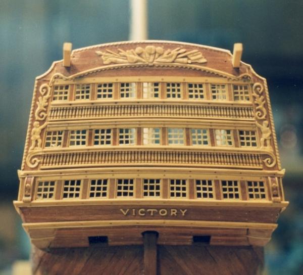
-
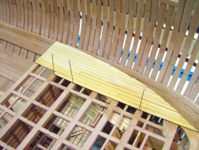
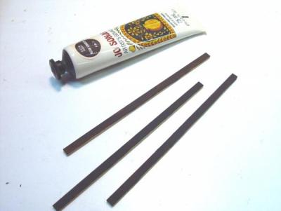
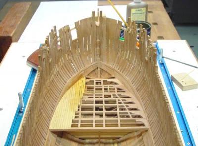
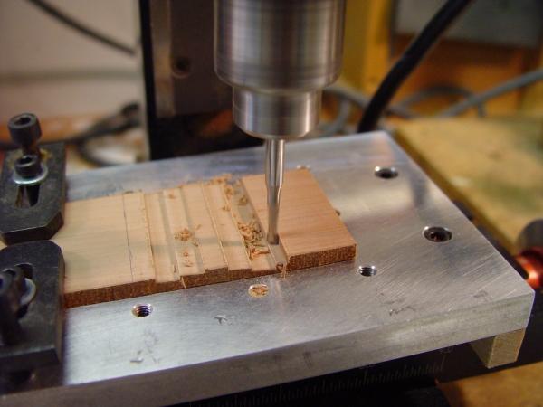
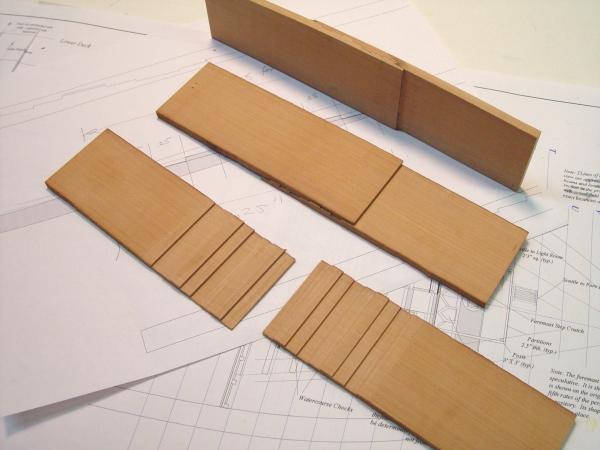
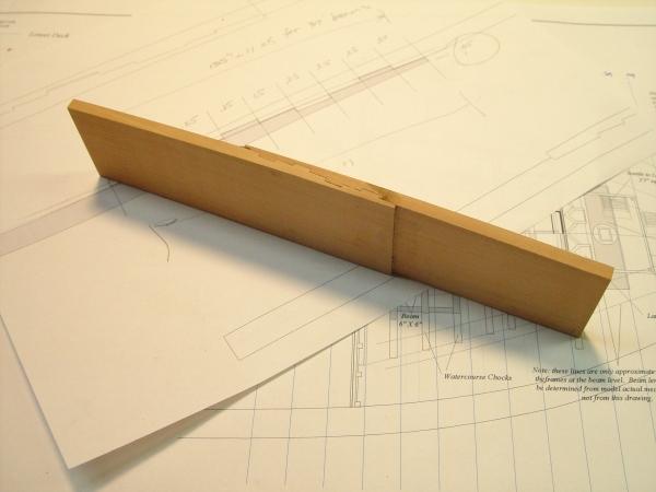
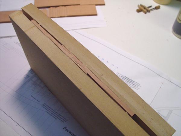
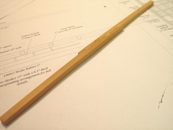
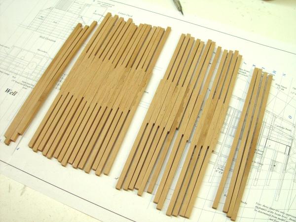
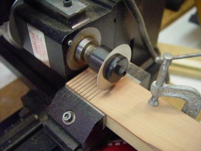
1:60 HMS Naiad 1797 Part 55 – Scarfed Deck Beams Posted 3/8/11 As timber supplies began to wane, it became necessary to fabricate deck beams from multiple pieces of timber. There might be two, three or four pieces used to make a beam. These beams may actually have been stronger than one piece beams, but I doubt this would have been reason to take on the large amount of additional work to make these. Also, there is not credit given in size requirements for made beams in any source I have seen. There is no information on which type of made beams were used on which ship. I decided to make the beams for the lower deck of Naiad in two pieces. Cutting all these joints manually in any reasonable amount of time seemed unlikely, quite apart from the obvious final quality issues. For this reason I decided to machine these vertical tabled scarfs on the milling machine on wide pieces of wood thicknessed to the beam width. The picture below shows this machining in progress on an 11 inch thick piece.. However, some work was required to get to this, which I will describe only briefly. The length and the angle of the scarf needed to be determined. The milling table was then set to that angle. The length of the scarf was then divided into segments. In this case a single table width of 15 inches (.25”) was reasonably representative of the originals, which varied somewhat in width. In the planned process, it was important the scarfes be symmetrical so that one pattern could be used for both pieces to be joined. The difference between levels of the scarf tables was set at a constant of 3 inches as were the depths of the end lips. This was as per the original. A one eighth inch milling bit was used. A repetitive cutting sequence using the calibrated hand wheels on the milling machine was developed. Following this sequence required concentration – for me at least – to avoid ruining the piece. After marking off the length of the scarf the first pass was taken to just skim the surface. If the right angle, table pattern and table depths were followed the last cut at the end would leave the right thickness for the lip - 2.5 to 3 inches. Below are some machined pieces in various stage of assembly. The apparent curvature in this and the next picture is photo distortion. These are straight. Two identically machined pieces are shown in the lower part of the picture. If machined correctly, these will be a very tight fit – too tight, so they need to be filed back a bit on the table edges so that they fit together easily, as shown in the middle view. At the top two pieces are glued together. This was done using a very darkly pigmented glue to make the joint quite visible. There is no point in doing all this if the joint cannot be seen and without the dark brown glue the joint is virtually invisible. The picture below shows the joint on an assembled beam blank. The process then followed that described in Part 54. In the picture below, 3” thick spacers are inserted in the round up pattern-clamp to compensate for the offset so the ends as well as the middle are held tightly. This picture shows the routed beam top. And the next picture shows a beam parted off on the scroll saw as described previously – ready to be run through the thickness sander. The next picture shows a finished beam ready to be fit up in the ship. The identical milling process will be used to make three piece and perhaps some four piece beams on the next deck up. Below is a finished sample, with iron bolts, which shows the expected final appearance, before finish, of the final joint. Two smaller bolts in each lip have not been installed in this piece. After scarfing, all the remaining steps, including shaping the trapezoidal cross-section follow the processes described in Part 54. The full set of lower deck beams with a few extras of each orientation are shown below. No bolts yet. These will be added after the fitting up, sizing to length and cutting the carling seats and other joints Having enjoyed proving out this process, and making the beams – I guess 10 to 12 hours of work, .it was time to go back to the detail work to finish the orlop. Ed
-
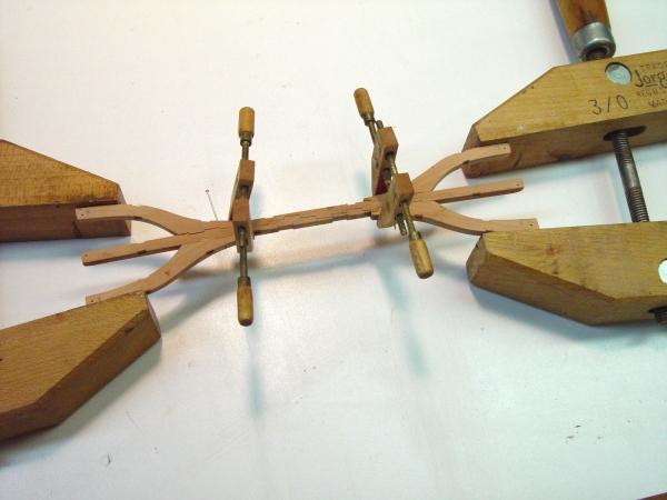
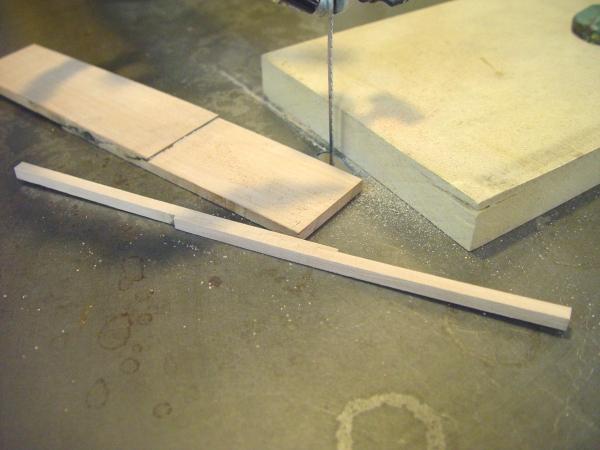
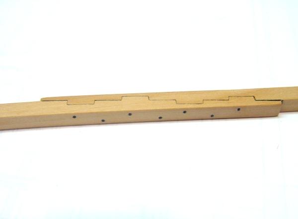
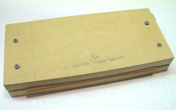
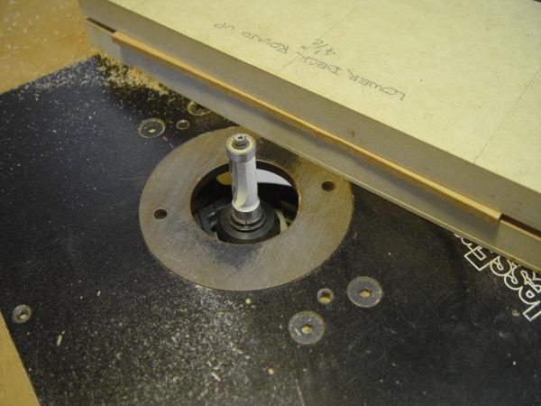
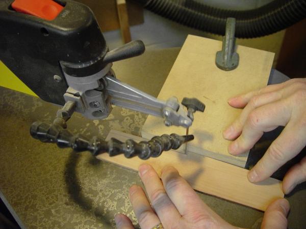
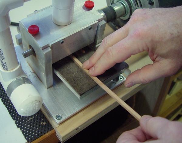
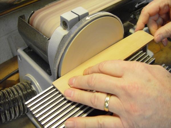
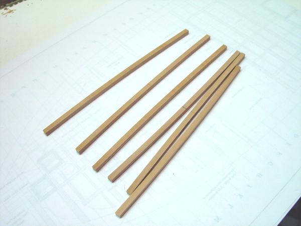
1:60 HMS Naiad 1797 Part 54 – Lower Deck Beams Posted 3/7/11 I needed some relief from all the small detail work involved in finishing up the orlop deck, so I turned to a process that has interested me for some time – the fabrication of the deck beams. There are several aspects of these beams to be considered. On the lower deck of Naiad these 28 beams are 11 inches wide by 10 inches deep, except for those at the fore and aft ends which become smaller in width. All the beams are rounded up in a circular arc so they are 4.5 inches higher in the center at midship, with the same curvature but smaller total roundup as the ends of the ship are approached and the beams become shorter. Also, toward the ends of the ship, due to the longitudinal sheer of the deck, the beams become trapezoidal in cross-section to maintain vertical sides, reaching an angle of a few degrees at the extremes on the lower deck. Finally, at this period longer beams were fabricated in multiple pieces joined by long tabled scarfs. There is no definitive data on which beams were made this way. I decided to make all but the smaller beams at the ends in multiple pieces with the scarfs - on all the decks above the orlop. In this part I will describe how the unscarfed beams were made and save the more complicated, and interesting, issue of fabricating the scarfs for Part 55. First the device shown below was made to give the beams a round up of uniform circular curvature. I had prepared patterns for forming these curves but the curvature is so slight that I did not feel that I could manually duplicate it accurately. So, equipped with the pieces of MDF shown in the above picture of the finished device, the radius of the curvature, which is between 8 and 9 real feet, a nine-foot length of 2 X 4, and a router table, the essential pattern was made in the following way. First one end of the 2 X 4 was attached with two nails on the centerline of the MDF piece. The distance of the radius was marked out from the face of the MDF along the 2X4 and a nail driven through it at that point into a block of wood secured in a vice at the same height as the router table. An arc the radius of the curvature could then be swung with the MDF so that its edge could be routed off to the correct curvature. The curved bottom piece was then be made from this first piece. The above picture shows two pieces of MDF made into a clamping device to hold the roughly 2-inch wide stock of the beam width. The picture below shows the router setup used to form the top pattern piece and later to round off the beams. This picture shows a piece ready to be trimmed. The protrusion is a bit exaggerated for illustration purposes. Only the slightest bit needs to protrude at the center. The bearing on the router bit follows the curvature of the top of the clamp. The lower part of the clamp is sacrificial and sometimes gets cut if it is out of line with the top, but the top piece is the guide. When the curve has been machined, the curve on the lower side of the beam is cut on the scroll saw set up with a fence to yield a beam slightly larger than the final depth. This step is shown below. The wide leftover piece was then re-clamped in the pattern device and the next beam shaped on the router – and so on. The beams were then sized to final depth and a smooth finish by passing it upside down through the thickness sander in the step shown in the next picture. For beams toward toward the ends of the ship, where they take on a trapezoidal cross-section, the top faces needed to be angled back before cutting the beam off on the scroll saw. To get that shape the top surface of the beam was sanded back on a disk sander with the table inclined to the angle of the trapezoid. This step is shown below. This step required care to only cut back the bottom surface not touching the top profile or the curvature would be ruined. I needed my higher-powered eyeglasses for this. Once this angle was formed the beam was cut off on the scroll saw as before. The beam was then run through the thickness sander as above with the sanded face down to create a parallel surface on the opposite side at the right thickness. An angle of 2 degrees is almost imperceptible at this scale, but on the upper decks it will be more pronounced so this process will become more relevant. Since this angle increases incremently moving forward and aft, numbering the beams is essential so they end up in the right place. Some finished one-piece beams are shown below. They of course still need to be cut to length, fit onto the deck clamps and have the carling seats cut as described in previous parts.. In the next part the process used to efficiently make scarfed beams will be discussed – an interesting and challenging problem. Stay tuned. Ed
-
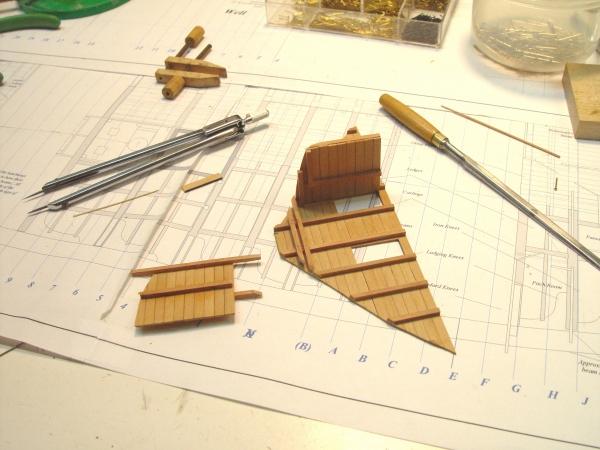
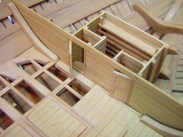
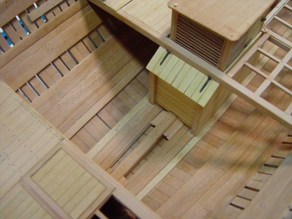
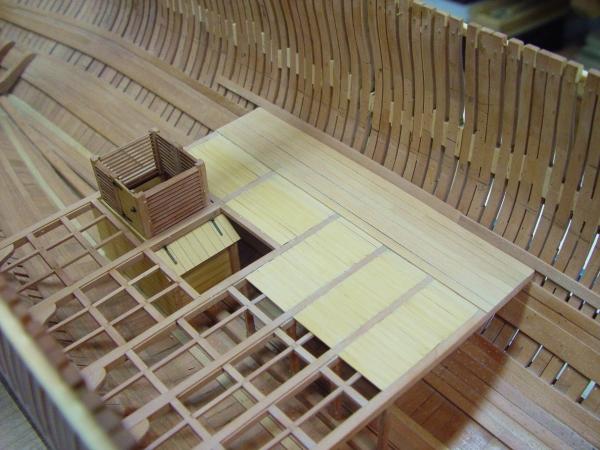
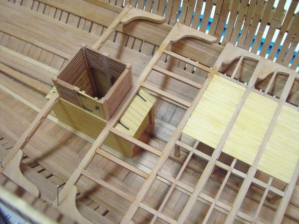
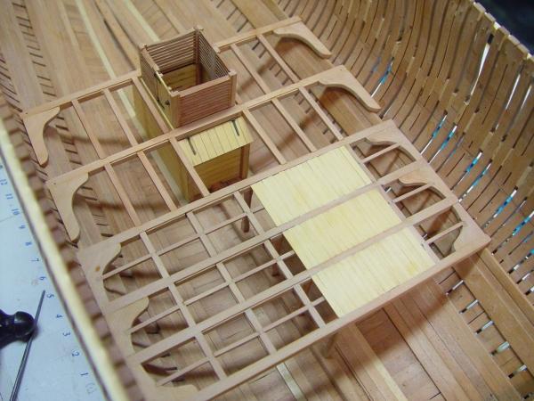
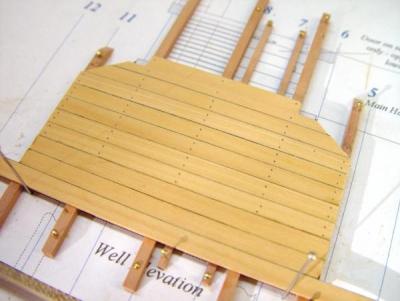
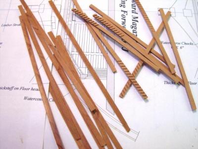
1:60 HMS Naiad 1797 Part 53 – Aft Magazine Posted 3/3/11 Making good progress this week. The picture below shows the standard knees on the aft platform installed, but not yet bolted. Also the bulkhead, which forms the forward end of the aft magazine has been fabricated and fit into position against the last beam of the aft platform. To shape the bottom curve of this bulkhead, a paper pattern was cut with scissors and fit against the side until a good fit was obtained. It was then traced on paper, to which was pinned the vertical stanchions, using the process described earlier. The bulkhead was then planked over on its forward face, leaving openings for the doors – on the left (in the picture) the entrance to the magazine, on the right the entrance to the light room. This planking was made larger than the pattern so that later there would be excess to allow final shaping to the hull. The picture below shows the sides of the magazine being attached. Before this step, these too, had to be shaped to fit the bottom of the hull, which curves upward dramatically in this area. In the next picture these sides are being attached with a cross piece at the rear keeping everything square. In the next picture most of the magazine detail has been completed – the floor, two doors into the magazine, one into the light room, stairs between the magazine doors and cartridge racks. The lantern is yet to be added. The next picture gives a good idea of just how cramped this space was, barely enough room to turn around. The doors were made by gluing paneling rails on to a 1 inch thick backing panel of Castello. The actual doors may have been simpler, but these were easy to make and look good. The hatches to the spirit rooms are still awaiting their hardware (the fish room was really used for more spirits by this period). In an attempt to wrap up the orlop some other chores were also attended to. The picture below shows the baseboards for two of the rooms on the forward platform, the boatswain’s store and the adjoining sail room. The sail room has 2” X 2” dunnage beams on the floor to let some air get under the stored canvas. Another larger sail room is located across the passageway from this one, but this unplanked area will not have partitions installed. When the lower deck beams are placed, the partitions to the rooms on this side of the ship will be added. At the orlop level the partitions were pretty permanent – unlike the upper deck partitions, which were dismantled and taken below when the ship cleared for action. I believe these held in place by wedges or removable battens at the foot. So, baseboards of this type were probably used to anchor the bottom of the more permanent orlop partitions. In any event these will help plumb the partition walls later. The next picture shows some more of these aft, defining what will be – forward to aft – the marines clothing room (perhaps closet is a better word), the slops room ( for seamen’s clothing, etc.) and the stewards room, conveniently located to keep and eye on the hatch to the spirits. The final picture shows 4” X 2” dunnage beams placed athwartship in the cable tier. Some input here would be welcome. I have placed only two of these. Both are on top of the beams where they will not interfere with the ability to lift up the loose planking in this area to get to the hold or to provide for cable drainage, or perhaps better air circulation under the cables. I cannot imagine that after going to the expense of making these removable - rabbeting the tops of the beams, lowering the carlings, etc. that they would then have nailed down dunnage on top that would foil the purpose of all this work. I see two possibilities – loose dunnage beams or running these fore and aft (or both). Of course the only time these planks could be lifted was when the cable was out. I will very likely add some more transverse beams, but I thought I’d give the experts a shot first. There are still more details to finish up before leaving the orlop in favor of “higher pursuits” – the lower deck. Ed
-
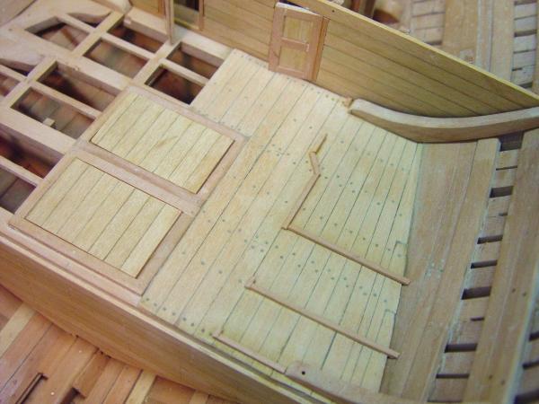
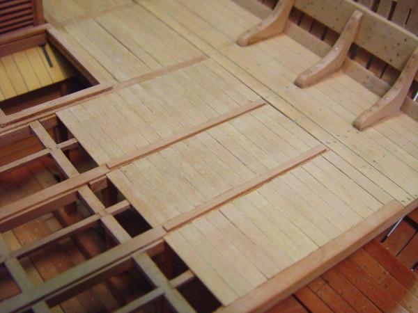
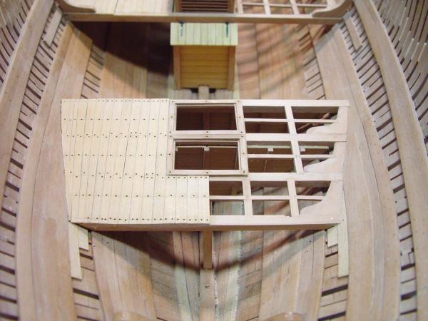
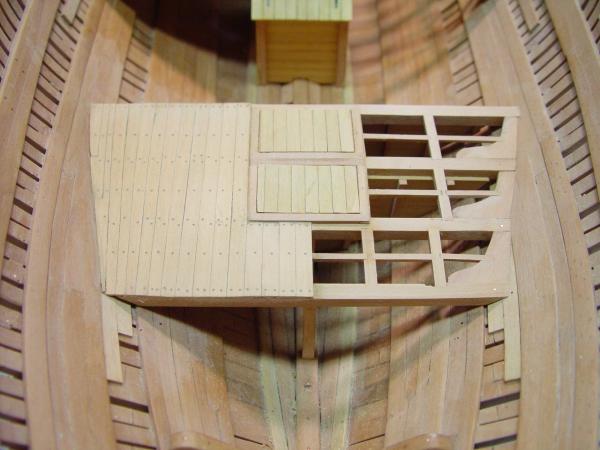
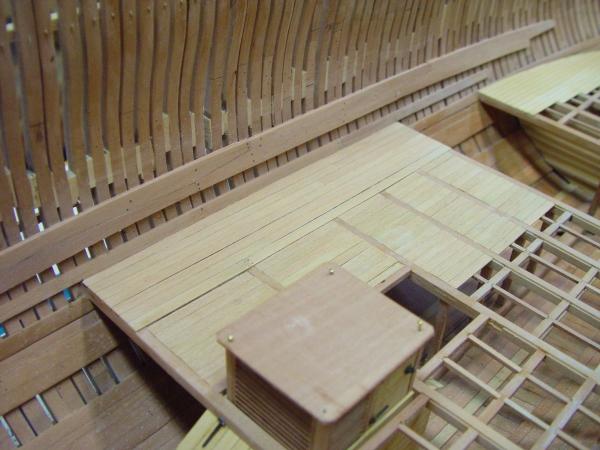
1:60 HMS Naiad 1797 Part 52 – Aft Platform Posted 3/1/11 Getting the forgotten Spirit/Fish Room partition in under the finished deck framing turned out to be not as difficult a task as feared. In the picture below the second of two segments is being glued and clamped into place. To slip it in, the partition bulkhead was made in two pieces with a vertical joint line that is hidden by the pillar on the forward side and the middle bulkhead stanchion on the aft side. The planking on this and the forward spirit room bulkhead was 3 inches thick. The next picture shows the forward bulkhead being glued and clamped. The next picture shows the finished bulkheads and the beginning of planking of the platform. Before extending this planking to the side, the copper bolts securing the beams were installed through the frames in the location of the temporary pin holes. The picture below shows the whole interior hull after the completion of the aft platform planking. For some reason the color in the pictures are more vibrant as the camera is moved further away. In the picture below, holes for treenails for both the decking and the coamings and head ledges have been drilled. And in the next picture the treenailing has been completed and two planked blanks, which will each become a “double-flap” hinged closure are lying in place on their respective scuttles. Except for the area aft of this platform the whole bottom below the orlop beams can now begin the finishing process, but first a few limber boards needed to be installed – just a few to give the general idea. I still want to have a good bit of the limber channels open so I can continue to enjoy picking out pins, wood chips and other debris which keeps falling into them. Some of these boards are shown below. The four standard knees still need to be installed on the aft platform and there are some other detailing chores to be done along the orlop level, but getting this platform in place was a bit of a milestone. Finally, a celebration cleanup of the shop was done so the last picture could be taken without all the usual clutter. This picture certainly highlights the difference in the Euro Boxwood and the Castello decking. Actually the difference is by no means this pronounced, but I do prefer the more subtle contrast of the Castello on the central and aft platforms. It may now be time to move on the the aft magazine. Ed
-
1:60 HMS Naiad 1797 Part 51 – Aft Platform Beams Posted 2/28/11 After completion of the lower deck clamps, including all the treenailing, some work was done to clean up the outside surfaces of the hull by filing down the protruding copper bolts for the orlop knees and some others left over from earlier work. The hooks in the bow were also bolted through the hull and their bolts filed down. The picture below shows the status of the work to this point. In this picture areas of the lower interior hull have been treated with the finish of beeswax dissolved in turpentine, hence the somewhat darker color of these areas. Several coats of this dilute mixture will be added until the wood is saturated with wax as the sovent in each succeeding coat evaporates. This needs to be done progressively because these lower areas will soon be unreachable. However, care must be taken not to coat areas that will eventually have to be glued. The next step was to install the four beams for the aft platform. In the next picture these have been positioned and temporarily pinned in place. Because some of these bolt to planking between the bands of thickstuff, some plank sections were added to support those. In this picture the marks for the carlings can just be detected. After fitting the beams to the side planking and pinning them, a line was scribed down their centers. From this the distance to the carlings can be measured, and using a straightedge, the inside edge of each carling was marked on the top corner of each beam with a knife while these were in place - to help assure alignment. The beams were then removed to the bench to cut the seats for the carlings. The next picture shows these back in the ship with the carling seats cut. In the above picture the knees and pillars have also been installed. This was done after cutting the carling seats The process for doing knees and pillars was covered earlier. The next picture was taken later after installing the carlings. In it a file is being used to cut the seats for the ledges, a simpler joint than the original construction, but one with identical final appearance. The next picture shows a ledge being glued in place with the aid of a surgical clamp. The surgical clamp allows a lighter touch than if you are squeezing on a pair of tweezers or pliers while trying to align the piece. Once you get the hang of releasing the lock without jolting the workpiece they are very useful. The next picture shows the finished deck framing with the coamings and head ledges for the two hatchways also installed. Unfortunately, I’m a little ahead of the game here, having forgotten to install the bulkhead between the fish room and the spirit room before doing the carlings. So, this will have to be done the hard way. Below this bulkhead and the one that goes forward of the first beam, dividing the aft hold and the spirit room, are shown being fabricated. The one the left, which will now have to be inserted under the completed structure has been made in two pieces, hopefully to make its final fitting and installation under and around the existing structure less difficult, perhaps actually possible. Some dismantlement may be required. We’ll see in Part 52. Ed

-
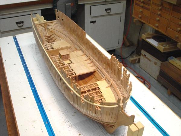
1:60 HMS Naiad 1797 Part 50 – Lower Deck Clamps Posted 2/21/11 Since the lower deck clamps needed to be installed to complete the standard knees on all the orlop platforms, it made sense to get these completely done before moving on the aft platform. I mentioned in the last part that this band of two strakes, 6 inches thick is all top and butt planks. The picture below shows this in progress. In this picture the curved pieces at the end are being worked on – fore and aft concurrently. Next is a close up of the other side. At the same time the treenailing of all the installed planks is being done. The next picture shows some of this tedious work in progress. All the treenailing for all this planking is being done using bamboo, drawn down to .024”. about 2” at 1:60. the holes are drilled to go about halfway into the frames, the bamboo rod is tipped with dark glue, pushed all the way into the hole and clipped off as shown above. The nails are then filed or sanded down. The next picture is of the same area a bit later after the clamps with their treenails have bee cleaned up a bit. The six standard knees shown here have just been glued in. The center one is still wet from glue cleanup. In the next picture the copper bolts securing these knees have been installed but not finished off. The bolts on these knees are staggered and go through the beam in the case of the horizontal leg and through the frames in the case of the vertical leg. The next picture shows these coming out through the frames in reasonably straight lines. They still have to be clipped and filed flush. These bolt holes of course pay no attention to joint lines, other bolts, etc, so the pattern on the outside will be a bit random and crowded. There were many fasteners coming through the hull. I believe in the appearance of all these fasteners authenticity will rule over aesthetics. This picture also shows the temporary spacers, which are being slowly removed as spaces are needed for clamping. They will soon all be removed once these clamps are finished and treenailed down. It occurred to me that almost all of the pictures lately have been close-ups showing details, so I added one of the whole model below. Ed

-
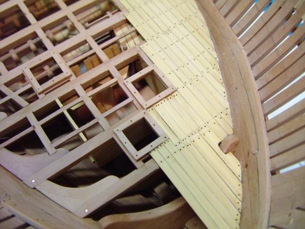
1:60 HMS Naiad 1797 Part 49 – Orlop Deck Posted 2/17/11 Its been an interesting couple of days in the shipyard. There have been some changes in direction, some rework and some interesting decisions to make. It starts with the first picture, below. I have been having some second thoughts about the very yellow European Boxwood decking. So, while we are still down here in the dark, dingy lower reaches of the hull, I decided to try some Castello in an area that will be virtually invisible in the finished ship. This planking to the outside of the removable planks in the center of the orlop platform can be seen below. The Castello has a slightly redder cast. The contrast of the Castello against the Pear is a bit more subtle than the Euro Box. I think it complements the pear better and is less of a bright yellow. So, I decided to go with it for the rest of the deck planking, saving the precious yellow real Boxwood for the outside hull planking and other external details that were historically yellow. Also, I have not been too happy with the removable planking and have been thinking about redoing it. The trigger for that can be seen in the next picture. The main hatch in this picture is too wide, a drafting error on my part. It should be 5’6” wide and as first installed it is over 7 feet. So, I decided to fix this and at the same time replace all the removable planks (not so removable in the model). So this picture soon turned into as demolition site. The above picture also shows a stretch of internal side planking called “the strake on the orlop beams.” This was installed for the standards to butt against at their bottom. Their tops will butt against the lower deck clamps, so these also had to be installed. The next picture was taken after fixing the hatch and replacing all of the removable planking.. Sorry, no pictures allowed during this ugly work. The new planking is Castello and matches the outer planking, which can be seen in this picture to be slightly raised. This is because it rests on top of the beams and the removable stuff sits in rabbets on the beams. These can be seen in the unplanked area. The roof on top of the well is just a temporary protective cover. I got tired of repairing the long fragile louvers every time I rubbed a finger across them. The installation of the “top and butt” lower deck clamps can be seen in progress in the above picture. More on that below. The next issue to face was the way to handle the standard knees on this deck. I will not elaborate further on this. Readers of this log will have seen the very interesting discussion, which followed my request for input on this. Like many decisions where definitive historical data is not available a judgment had to be made on this. So, after deciding, work proceeded to get these installed. Doubts perhaps, but no regrets. These were made by the same method as used for the lodging knees. The profile was cut into a thick piece of pear on the bandsaw, filed and sanded to shape and sized. The individual knees were then sliced off of this piece on the circular saw. The grain on these runs basically from tip to tip avoiding end grain through the arms. Not as good as compass timber, but okay. The picture below shows pieces at different steps in the process. The first of these has been fit up and is being glued in the next picture. The next picture shows all six of these being glued in. On the model these are on top of the deck. They may have been down on the beams, but details of these is lacking. There would be no visible difference on this side. On the other side, which is unplanked they will be down on the beams. And in the next picture copper bolts have been installed. The holes for these were drilled from the inside, all the way through the frames. After the first couple I started staggering the boltholes on the bottom legs, which I believe was the practice to avoid creating a weak line along the grain. The bolts in the vertical legs are more in a line because they need to go through the frames which are not always directly in line with the knee. The bolts were glued in with CA and filed off flush inside and out. This picture also shows the treenailing - in the deck, the deck clamps and the strake on the orlop beams. The removable planking is, of course, not nailed. The above picture is pretty accurate with regard to color. I like the more subtle contrast between these two woods. The next picture shows the most aft section of the deck clamps being glued in place. This piece was bent to its compound curve shape by boiling it for about ten minutes then immediately clamping it in the position above. The next day it was removed scraped and sanded clean and it is shown here being glued in. Surprisingly there was almost no spring back These top and butt planks were cut on the circular saw using two specially made guides to cut the two different angles of taper and to yield the correct width at the apex and the ends. The following picture shows the two different taper guides, one with a plank in position to be cut. With these two guides additional planks can be easily duplicated if needed later. This worked quite well and the planks fit together without adjustment. The only setup required to use these is to set the width of the plank ends by moving the rip fence. Ed


-
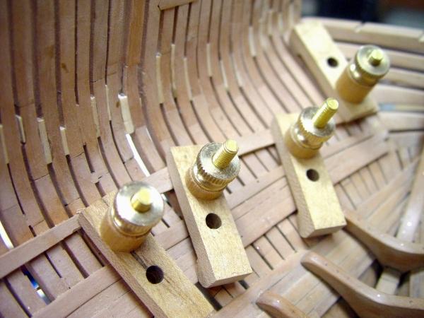
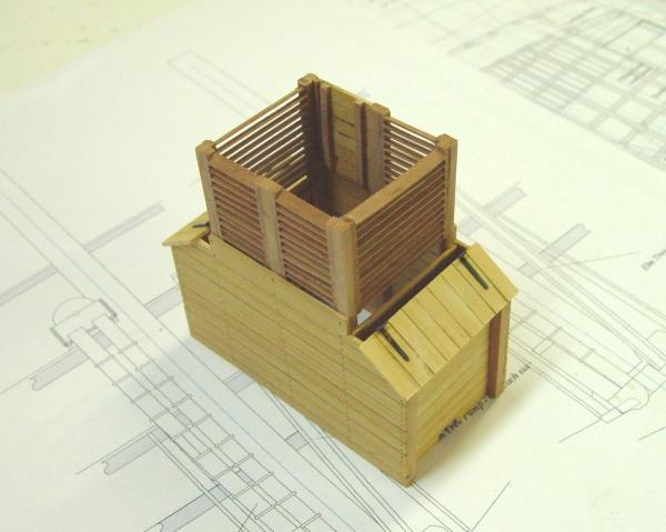
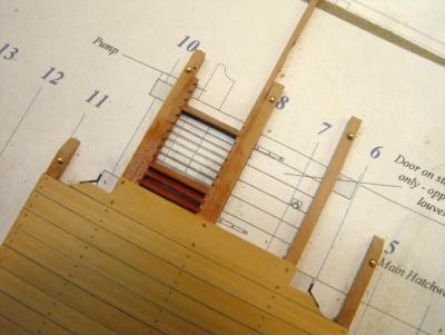
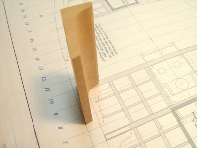
1:60 HMS Naiad 1797 Part 48 – Well and Shot Lockers 2 Posted 2/10/11 Installing the remaining louvers and the lids to the shot lockers with their strap hinges finished the well/shot locker assembly. In this picture it is resting on a drawing of the pumps. Before the assembly could be installed in the ship, provision had to be made for anchoring these pumps to the bottom. The pump shafts will be installed much later during the detailing of the upper deck. I do not plan to model all the inner workings of the pumps. Their shafts and external features will be detailed but not the innards. The next picture shows the six small dowels that will hold these shafts later. These are a non-prototype modeling convenience. There are six shafts for the 4 pumps. The boxwood blocks in the above picture are the bottoms of the Cole chain pump housing. Each has two shafts through which a continuous chain fitted with disks carries the water upwards, dumps it into a cistern and continues back to the bottom for another drink. There are also two Elm Tree pumps each with one hollow shaft fitted with a plunger and check valve. These were lower capacity, but higher pressure and were much like well pumps that some of us may remember from our childhoods. When these shafts are made they will have matching holes to fit over these dowels. The next picture shows the well assembly glued in and the two beams at its fore and aft ends set in place temporarily. Before installing the beams, their lodging knees needed to be fitted. These are glued to the beams only in the next picture. When the glue on these dried, they were removed to have the bolt-holes for holding the knees to the beam drilled on the drill press. Bolts were then installed, two on each knee, and the beams permanently fitted. The next picture is an overhead view of the installation. In this picture the carlings between beams four and five are installed. The next picture shows this in a broader view of the hull. In the last picture all the carlings have been installed. The larger opening just forward of the well is the main hatch. I have wondered why this opening was allowed to be obstructed by the forward shot locker, which takes up quite a bit of the opening. It doesn’t seem like very good design, but obviously it worked in practice since it is a common peculiarity to all the contemporary frigates I’ve seen. The design of the shot lockers is also curious. It was of course important to keep all this weight as low and as centered as possible, but what a chore it must have been to get the 18 and 32 pound balls out of these five foot high boxes. Obviously someone had to get inside. The next step will be to drill and bolt all the lodging knees to the hull frames. This will secure the beams completely – same as the original. Following this, the ledges will be installed and the port side will be planked. We can then move on to the aft platform. Cheers, Ed


-
Thank you both for these comments. Peter, I hope the shipway will serve you well. One tip: To keep small parts or tools from dropping into the T-trak, cover it with masking tape. I have not done this but often wish I had. The alternative is to keep a pair of tweezers handy. Ben, thanks for the vote of confidence on Volume II. Ed
-
In response to questions on the content of the future Volume II, I have decide to attach a pdf of the outline of contents for that Volume, which is in progress at this time. I have also attached a similar pdf showing the contents of Volume I. Naiad Vol I Contents.pdf Naiad Vol II Contents.pdf The Volume I contents are taken directly from the published book chapter and sub-chapter headings. Volume II contents are still in progress, but page 1 of the PDF is pretty well along. Page 2 is more tentative and subject to revision. Volume II covers much more diverse subject matter than the first volume. It will take the model to completion. To make room for detailed methods descriptions, pictures and diagrams, many of the processes that will be applied in multiple situations are described thoroughly, only when first used. These “anchor” processes are denoted with *** in the pdfs. When they are used later, only variations or special circumstances will be discussed. This has reduced repetition and made room for more content. This labelling will also permit easy reference to these basic processes from the table of contents. I hope you find this helpful I am very excited about Volume II and hope we can get it into print this year. Of course that is uncertain at this point, since it depends on my finishing the model, the drawings and the writing of the book – not to mention the publishing process as well. Thanks for your interest. Ed Copyright 2013 Edward J Tosti
-
Thanks for these comments. Mark, to answer your question on Volume II - you are not the first to ask - I have attached pdfs of the Volume II contents outline along with a similar pdf for Vol I. Naiad Vol I Contents.pdf Naiad Vol II Contents.pdf The Volume I contents are taken directly from the published book chapter and sub-chapter headings. Volume II contents are still in progress, but page 1 of the PDF is pretty well along. Page 2 is more tentative and subject to revision. Volume II covers much more diverse subject matter than the first volume. It will take the model to completion. To make room for detailed methods descriptions, pictures and diagrams, many of the processes that will be applied in multiple situations are described thoroughly, only when first used. These “anchor” processes are denoted with *** in the pdfs. When they are used later, only variations or special circumstances will be discussed. This has reduced repetition and made room for more content. This labelling will also permit easy reference to these basic processes from the table of contents. I hope you find this helpful I am very excited about Volume II and hope we can get it into print this year. Of course that is uncertain at this point, since it depends on my finishing the model, the drawings and the writing of the book – not to mention the publishing process as well. Thanks for your interest. Ed Copyright 2013 Edward J Tosti
-
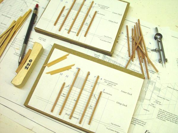
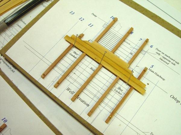
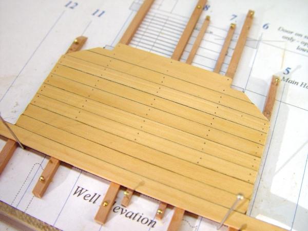
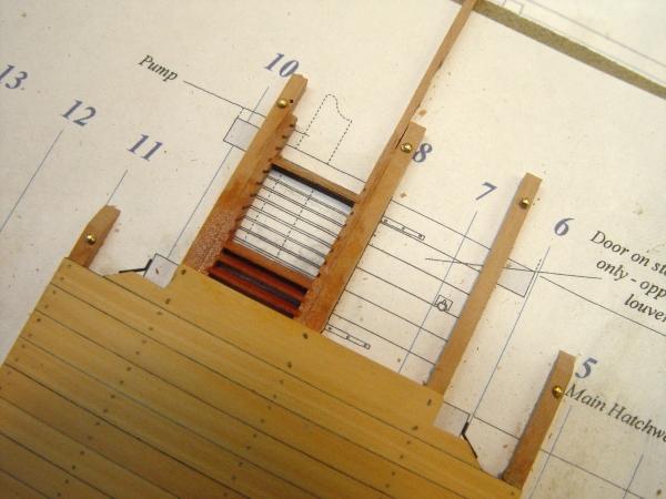
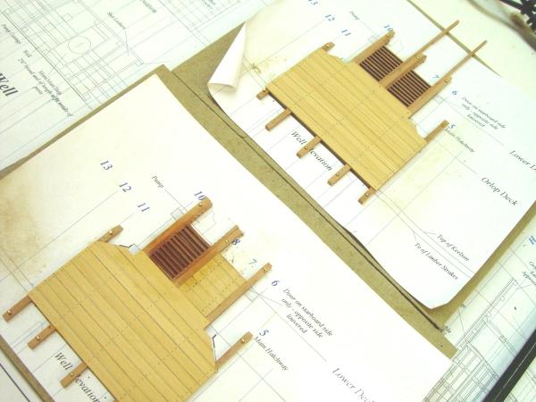
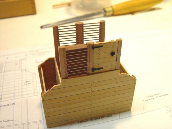
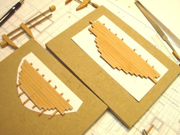
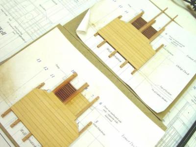
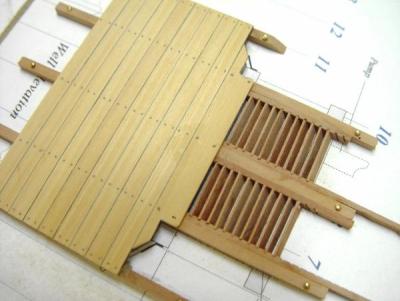
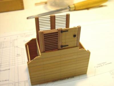
1:60 HMS Naiad 1797 Part 47 – Well and Shot Lockers Posted 2/7/11 The decking of the orlop started in the last part could not be completed until all the beams were installed and before installing the last two of these the well and shot locker structure had to be made and installed. The first strp in making this is shown below. First two copies of the elevation view of the structure were placed on pieces of Homasote board and lengths of 6 X 6 timber were fastened in the locations of the four columns. These were made longer than needed to allow them to be pinned to the boards at their ends. Both sides of the well/shot locker structure were built simultaneously, so there were two of these layout boards. This picture also shows the specially cut top planks for one side, which would be the first to be installed. The next picture shows the first of the 2.5 inch thick planking being glued to the columns. Two of these were glued at a time and were held against their neighbors and down with pins. The caulking line between planks was done by a method I believe I described earlier and one that has now become my standard for planking caulk lines. The planking stock is coated with raw umber acrylic designers gouache on one side so that when the planks are ripped off one edge is dark. They are then glued with dark glue made by working raw umber artist’s pigment into ordinary yellow glue. The next picture shows this effect on one of the sides, which has also been partially treenailed. The treenails are 1” (.016”) bamboo. This picture also shows the back bracing for the door to be installed on the starboard side. Planks would be glued to these (but not the columns) to build the doors. This is a convenient way to assure the fit. These overlength door braces would be cut off later. Except for the space taken up by the door, all sides of this structure between the orlop and lower decks was constructed with ventilation louvers. Side frames for these were dadoed on the milling machine at 30 degrees by the process used earlier for magazine ladders. Some of the machined sides and some 1” X 8” slats are shown in the next picture before being cut to size and installed The next picture shows the louver construction in progress. First the two vertical frames were dry fit into place and two slats were cut so that when slipped into their groves the sides would be pushed against the columns. When this was fit up the pieces were removed then replaced with glue and aligned. The rest of the slats were then glued into their slots. The next picture shows the louvers installed in the two side assemblies. The louvers in the fore and aft faces will be done after all the walls are assembled. This also shows the planked up door. The next picture shows a close up of the port side wall assembly. The four fore and aft partitions were made by edge gluing planks on waxed paper then cutting the panels square on the circular saw. These were then glued to their columns to form the four-sided structure, which is shown below. The door hinges wire made from copper wire and small pieces of brass plate. This method was described earlier in the section on the magazine light room shutters. The door latch was another small plate, with a ringbolt. All were chemically blackened and glued on with CA. These pieces are too small for bolts – at least for me. Note the square notches on the top planks. These fit against and under the orlop deck beams. Before laying out the side wall assemblies, and again after removing them from the pattern, the space between these beams was double checked to make sure this would all fit snuggly. The assembly is very slightly oversized at the bottom to allow for trimming to fit tightly between the lower side of the orlop beams and the limbers strakes on the bottom. The lower part of the transverse panels will also have to be shaped to fit over the keelson. All of this will covered in the next installment. Cheers, Ed Copyright 2013 Edward J Tosti


-
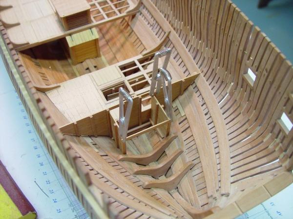
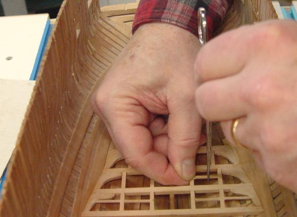
1:60 HMS Naiad 1797 Part 46 – Orlop Deck Posted 2/5/11 In the first picture the first four orlop beams have been installed. The lodging knees were first attached to their respective beams. They were then removed for drilling of the bolt-holes throught the beam, after which copper bolts were installed. They were then permanently glued into place with their pillars. After removal of the pins shown in this picture the pinholes were filled since there were no bolts in these positions. The next step was to drill holes through the knees and the hull frames. This can be difficult. Its hard to drill from the inside of the hull and if drilling from the outside getting the hole to emerge near the center of the knee thickness is chancy at best. I spent a lot of time thinking about this problem before devising the drilling fixture shown below. It is fairly simple and was constructed in a couple of hours from various materials lying around the shop. It is essentially two planks of laminated hardboard hinged together at one end. The lower plank can be clamped to the building board using the T-slots. A piece of threaded rod through a contained nut at the end of the top board allows height adjustment.. Two cross fences are used to guide the Wecheer drill, which has enough parallel side to stay aligned. It could be put in a square cradle as a possible improvement. The drill bit is aligned with the hole location and slid along the fence to drill the hole. The fixture is then moved fore and aft to locate the other holes. The fixture can be flipped around to get at holes further aft. Here is another picture. I believe I am using a number 74 drill here. The first few holes were a success, so I now plan to use this for all bolts through the hull to internal structural members. Precentering holes is not very practical here and I did find that locating a holes where the frame is angled may cause the drill to wander on entry. This was corrected by shortening the exposed bit length, starting the hole, extending the bit out, then completing the hole. Bolts were then inserted in the usual way. Once the four beams were installed, the next step was the carlings. In the picture below I am trimming one side of a mortise to fit a carling. The holes were left on the tight side to allow some adjustment in carling location so they would run in straight lines. The accuracy of my marking out is not good enough to assure this in the initial joint layout, so this procedure helps get them straight. Its too early to tell if this device is a god solution to this problem and like any tool some practice and learning is needed, but so far it looks promising. Then next picture shows the carlings installed. As mentioned earlier these are at different heights due to the way the planks were laid on the orlop deck. Except for the outer carlings which are flush with the tops of the beams, those in this picture are set down at the height of the ledge in the rabbet. The next picture shows this structure after the ledges have been installed. The last picture shows some of the short removable planks installed between the first tow beams on the port side. In keeping with the format, decks will be at least partially planked on that side and the structure is being left open on the starboard side. Ed Copyright 2011 Edward J Tosti

-
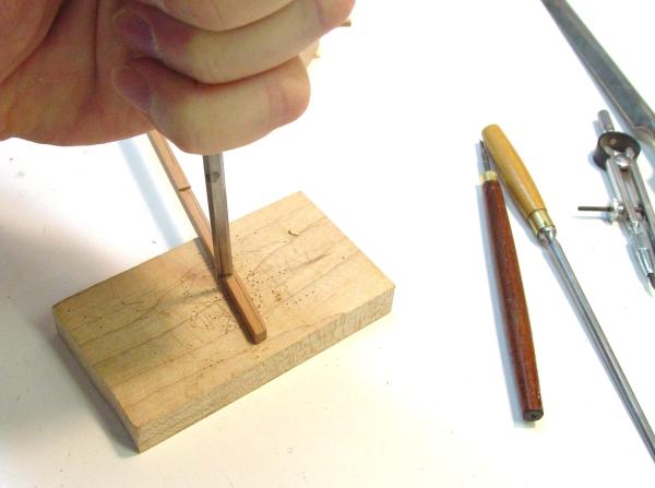
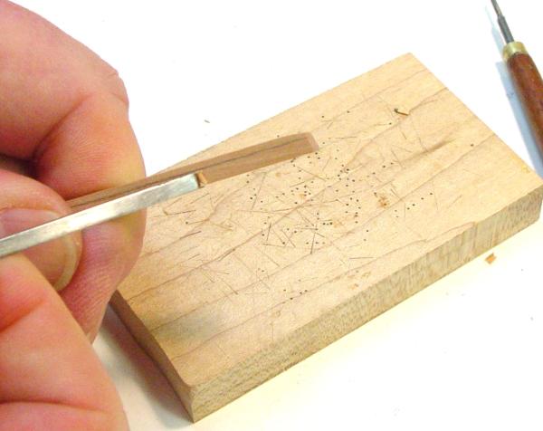
1:60 HMS Naiad 1797 Part 45 – Orlop Framing Posted 2/2/11 With the mortises and rabbets cut on the orlop beams, the next step was to make and attach the lodging knees. To make these a blank cut to the shape of the knees is first made as shown below. This piece was cut from a large piece of pear stock on the band saw fitted with a narrow blade with a small tooth count per inch. Fewer teeth cut much better through stock of this thickness. This was the smallest blade I had on hand. It appears to be about 1/4inch with about a 5 tpi tooth count. It could be smaller with fewer teeth and it did leave some burn marks. These were removed with a round rasp during the final shaping and sanding. The next step is to slice off the 7 ½ inch thick lodging knees. A few of these are shown below. These pieces are then cut to the length between beams using the rip fence on the small circular saw so the faces will be parallel. They are then shaped on a disk sanderto fay against the hull frames and glued to their respective beams only. These beam/knee assemblies will later be removed for the drilling of the fore and aft bolt-holes. A process is being developed to drill the bolt-holes from outside the hull but this is not ready for prime time yet. Below is a picture of the four forward beams with their knees being attached. Note that the orientation of the knees changes at the deadflat, so the second beam has no knee attached. The installation and other framing for these four beams will probably be completed before going on to the last two, which surround the main hatch, the well and the shot lockers, making them a bit more complicated. In the next picture the pillars that support these four beams off the keelson are being made. The picture also shows the measuring device used to measure the length of these between the keelson and the beam. This was made from telescoping square brass tubing with tabs silver soldered on and a tightening screw. The pillars have square tenons top and bottom and a chamfered on their sides. It was common for corners throughout the ship to be rounded off or chamfered to prevent injury from the sharp corners, especially in rough weather. Sharp corners could easily cause fractures. The next picture shows this chamfering being done with a file in a simple fixture made for this purpose from hardwood to help assure uniform corners. The rounded tops and bottoms of the chamfer were done with a round file first. The fixture was made by routed a 45 degree grove in a piece of Castello then trimming the top beck on the thickness sander until the right amount of chamfer was achieved when the file bottoms on the fixture. I am not holding the pillar down in this picture to give a clear view. The next picture shows the first two beams with their pillars fitted up temporarily. A small square was used to locate and mark the fore and aft face locations of each beam on the keelson. A square mortise was then cut on the beam centerline in the keelson and on the bottom of each beam, This fit up is still temporary. Ed Copyright 2011 Edward J Tosti


-
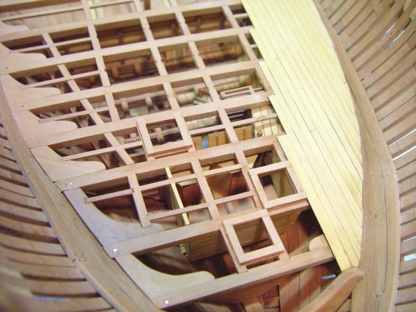
1:60 HMS Naiad 1797 Part 44 – Center Orlop Beams Posted 1/31/11 With the completion of the fore platform, work began on the center orlop – officially the orlop. Unlike the fore and aft platforms, the orlop beams actually rest on the notched orlop clamps like beams of the other decks. The making and fitting of these beams was discussed in Part 31. The first step here was to retrieve those beams from storage, fit them up and pin them securely in place as shown below. Once pinned down, the centerline was scribed with a sharp knife on the top of these beams. Then the locations the inside edge of all the carlings were marked on each beam in place, to help assure alignment. The next step would be to cut the mortises for the carlings. There are three tiers of carlings on each side of the ship. The cutting of the joints in the beams for these is somewhat complicated by the fact that most of the orlop deck consists of short removable planks that are set in rabbets on the beams so when in place the tops are flush or slightly below the tops of the beams. From the outside tier out the deck planking rests on top of the beams in the normal way. This requires the carlings in the inner tiers to be set below the tops of the beams so they and their ledges can support the short planks at the lower level. The carlings on either side of the hatches are set to the tops of the beams and have no planks on them. The outer tier of carlings is also set to the tops of the beams in the normal way. If this seems confusing, it is, and I was convinced there would be some new additions to the scrapped parts box before too long – so I took extra care in laying out all these joint locations. The first step in the process was to cut all these mortises in the normal way – as if all the carlings would all come up to the beam tops. These were all cut with small hand chisels in the way described for the fore platform beams. The picture below shows the beams back in place after this step. The wider spacing between central carlings in the aft three beams in the above picture is to accommodate the main hatch and the hatch for the well, which will rise up between the last two beams in the lower end of the picture. When this was done and checked the next step was to cut the rabbets in the tops of the beams to take the short sections of planking. The picture below shows this rabbet on the finished after most beam. The rabbets were cut on the milling machine set up as a router in the picture below. The beams were hand fed between the appropriate mortices – very carefully – and of course to the right, against the rotation of the cutter. Once these rabbets were cut, the mortises for the depressed beams were enlarged downward so their carlings would be at the lower height. This was done by marking the new lower edge with a compass with an extended point as shown earlier, extending the sides of the mortise with a chisel, cutting the new bottom ledge and then squaring up the joint. As mentioned earlier these were cut slightly on the small side to allow for final alignment later when the carlings are actually installed. The remaining pictures show all this joinery on these beams that are resting temporarily in position. The first picture is looking aft. In the next picture it is somewhat easier to see the deeper mortises on the second tier in the aft three beams and all but the outer tier in the rest of the beams forward. The last picture is just another view of these finished beams. I am happy to say that there were no scrapped beams. Ed Copyright 2011 Edward J Tosti


-
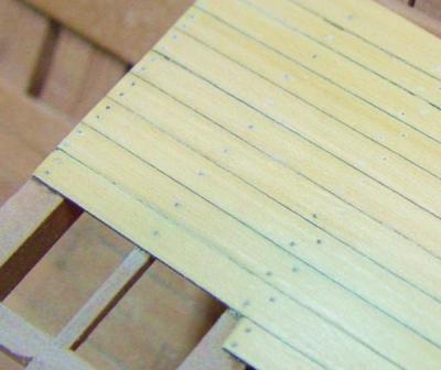
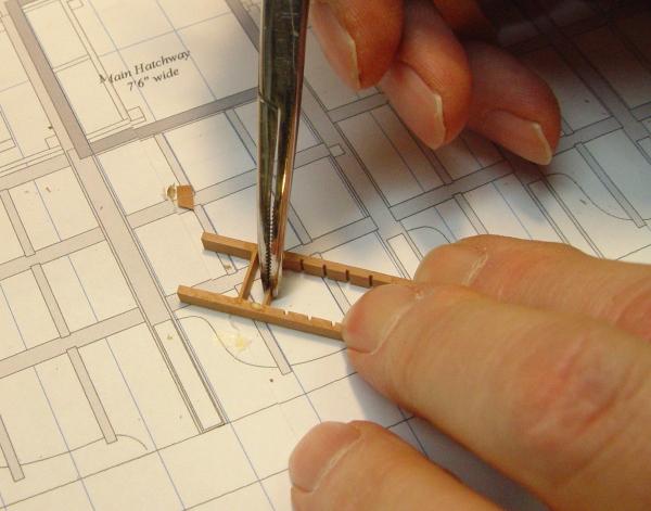
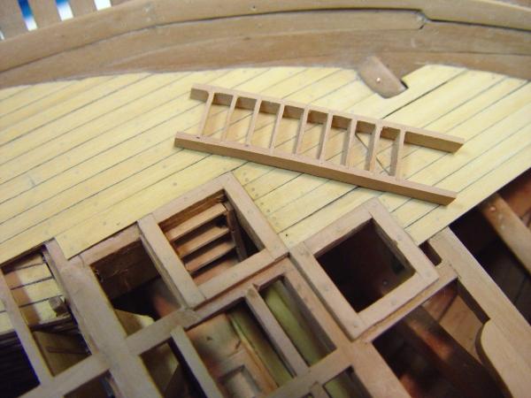
1:60 HMS Naiad 1797 Part 43 – Fore Platform Wrap Up Posted 1/27/11 Before finishing the planking work on the fore platform, the coamings for the three scuttles had to be installed. These are 6 inches wide and three inches deep. They are joined at the corners with a lap joint, which is through treenailed to the supporting timbers below. The ledges that were framing one side of the scuttles in previous pictures were removed and replaced with carling-sized timbers. The following picture shows the framing of the three scuttles. This picture also shows the reworked light room. These changes were made following some good input from Gary on what the backs of the lanterns looked like. Previous pictures showed a partition. This was removed along with the lanterns. They were given new metal backs and light reflectors from their sides to the window frames. Doing all this after all the platform framing was done was lots of fun. The next picture shows all the intending planking installed. There is a break in the planking at the center of the foremost beam. David White shows this in his Diana drawings. My guess is that thicker plank was needed to span the distance from that first beam all the way to the thickstuff on which the fore ends of the planking bed. I made this planking 2 inches thick vs. the 1 inch planking on the rest of the platform. I also took it aft to the fore peak scuttle rather than insert very short pieces of the thinner planks – a little artistic license and common sense. In this picture all the holes have been drilled for treenails for the planking and the scuttle framing. Following is an overhead view of the whole platform at this stage. After finishing the treenailing and leveling the decks, all that remained was the three ladders. Don’t ask me why I didn’t install these earlier. It would have been much easier. The following picture shows the ladder sides being rabbeted for the treads. This was done using a slotting blade the thickness of the treads – about 1.5 inches. The calibrated feed allows these slots to be precisely located at the same spacing. The next step is to cut the edge of this piece and another like it to the ladder angle. The ladder sides are then ripped off these two mirrored pieces to give right and left hand sides. The next picture shows a ladder being assembled. The sides of the ladders were made intentionally thick so they could be sanded down to give a tight fit with the scuttle opening. When the fit is loose its very difficult to position them correctly when you have to do this after the framing is done – they keep dropping through.. A tight fit makes this easier. Next time these will be done before the framing. The next picture shows the ladder for the forepeak scuttle waiting to be installed. This picture also shows the ladder to the light room after installation and the next picture shows the ladder to the magazine. The last picture shows all three ladders in place. The fore platform is now complete, except for the standard knees which will be done after the lower deck clamps are installed. Ed Copyright 2011 Edward J Tosti


-
1:60 HMS Naiad 1797 Part 42 – Fore Platform Decking Posted 1/24/11 Having finished the framing of the fore platform, the next step taken was installation of some decking on the port side. This will be quite a limited amount to allow as much visibility to the magazine as practical. I have not decided how much of the partitions will be done. As only the port side will be decked, and that only partially the modeling of these simple little boxes may not add much to the model. We’ll see. In the picture below a portion of the intended decking is down. In this picture the most recently glued piece is held against its neighbor with a few pins, lightly tapped into place. The excess glue has been cleared with a clean water brush – hence the wet spots. I am testing out a new approach to highlighting the caulked joints between planks. In the magazine this was done with black paper. For this deck I have used raw umber acrylic gouache to paint one side of the planking wood before slicing off the planks. The gouache and painted blanks are shown below. One side is painted with gouache right from the tube to provide some thickness. The one painted side will end up on the edge of the planks when they have been sliced off on the circular saw. I also plan to test this with dark brown acrylic household paint, which may be easier to apply uniformly. Also, I am using homemade dark glue to secure the planks, including their edges. I have been experimenting with a number of ways to darken glue and the one used for this work has been the best so far. Yellow glue, in this case Elmer’s Carpenter’s Glue was darkened using raw umber Sennelier artist pigment. This is a finely ground high quality pigment. One teaspoon was mixed with about six ounces of glue. To avoid the pigment clumping and settling in the glue bottle, the pigment was first incorporated into a small amount of glue, maybe two tablespoons. The ideal way to do this is with a stone or ceramic mortar and pestle. I used a soup bowl with a pestel made from a rounded Teflon rod about ¾” in diameter. The pigment needs to be ground into the glue thoroughly. When this was done, the remainder of the six ounces was poured into the bowl and that was mixed thoroughly. The glue bottle was thoroughly washed out before returning the dark glue to it. After about two weeks, there is no sign of settlement at all. The darker glue does need to be washed off more thoroughly than normal glue because the residue is more noticeable. The pigment is encapsulated in glue so does not stain the wood at all. The next picture just shows the remaining planking in place. There may be some more added up front later. The next few pictures show the treenailing process. Before starting this, the decked area was scraped down using a Flex-cut straight scraper. These can be used as bought but work better if a slight curl is put on the edge with a burnishing rod. . In the first picture holes have been center-indented with a scriber point and drilled. A .016” bamboo treenail rod is inserted into a hole with some of the dark glue. In the next picture the rod is being clipped off with small diagonal cutters close to the plank. The cutters are then flipped over and a straight cut is made on an angle close to the end of the bamboo. I like this approach because individual nails do not have to be cut. This reduces waste and avoids having to handle the small nails. In the next picture after the excess glue has been washed off and the wood has dried, a fine cut flat die sinker file is being used to take the nail tops down to plank level. In the last picture the surface of the planking has been sanded to a consistent smooth finish first with 220 grit paper then with 320 grit. Only some of the nails are installed in this picture and the overhead light reflecting off the boxwood somewhat washes out the pale yellow of the wood. In this picture also, the thiness of the 1” orlop planking is very apparent. Because it is so thin, it needs to be made a bit thicker to withstand the scraping and sanding. In the next segment we will probably be starting in on the central orlop platform, the well and the shot lockers. I’ll finish this deck when I get the design of the scuttle coamings cleared up. Ed Copyright 2011 Edward J Tosti