EdT
-
Posts
2,214 -
Joined
-
Last visited
Content Type
Profiles
Forums
Gallery
Events
Everything posted by EdT
-
Hi Mark, I will try to post the next three parts today covering the blackening of the main wale. They may answer your questions, but I haven't re read them, so I will just list some points. -wale blackened after intalled but before any surrounding planking, dark glue inn wale joints. - all treenails, bolting, finished first. -wale blakened with dilute acyrlic ink to yield semi-transparent finish -wale dampened to raise grain, dried then sanded to 400 grit. - masked top and bottom with good painter's quality tape- dampened wale before ink coat, then subsequent dilute ink coats before ink dry - this eliminates any streaking - test first Ed
-
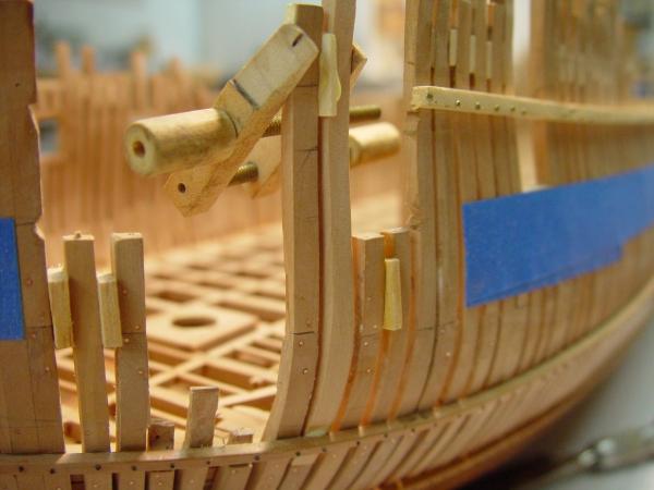
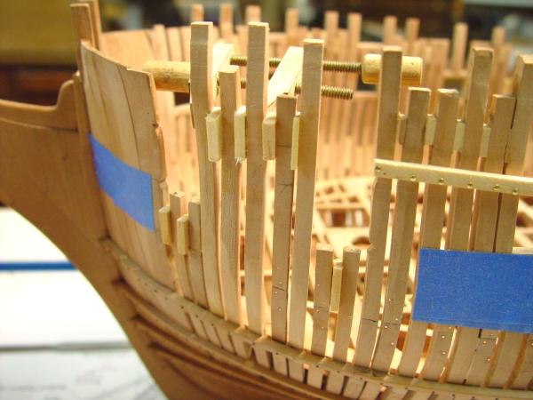
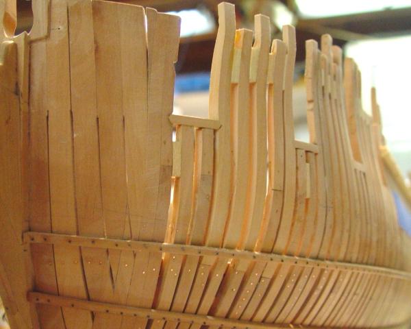
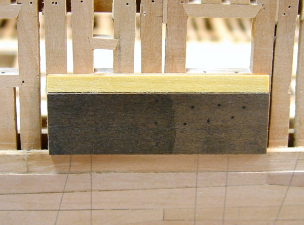
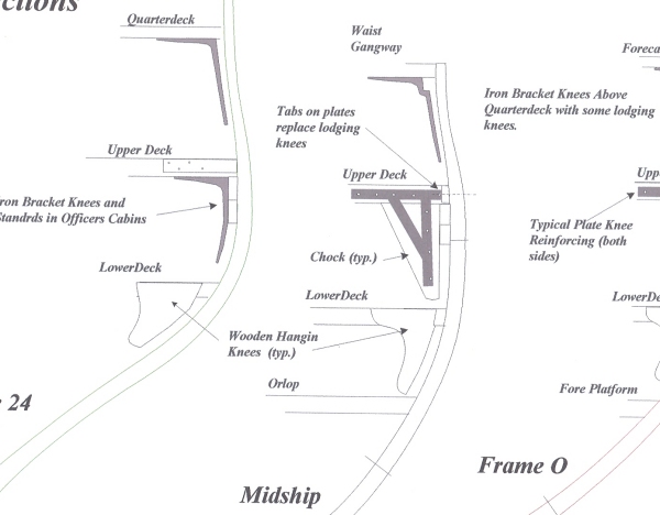
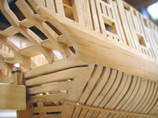
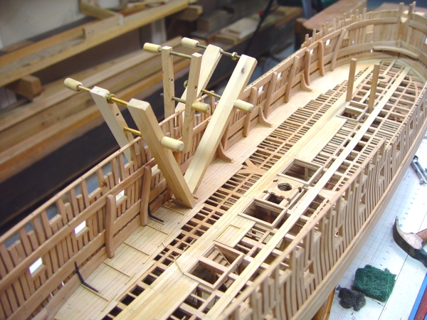
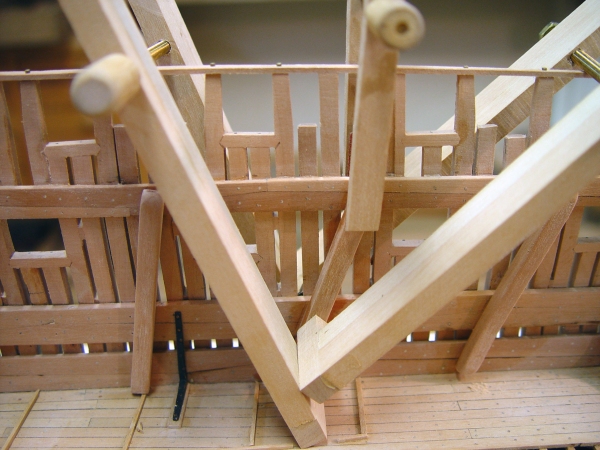
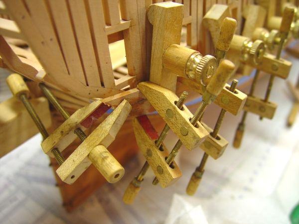
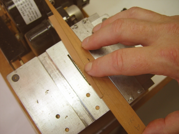
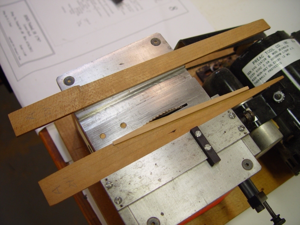
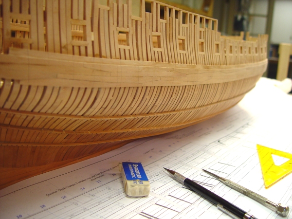
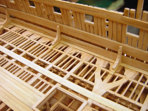
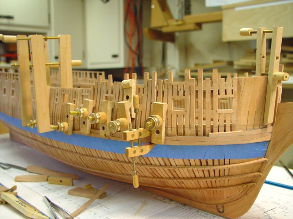
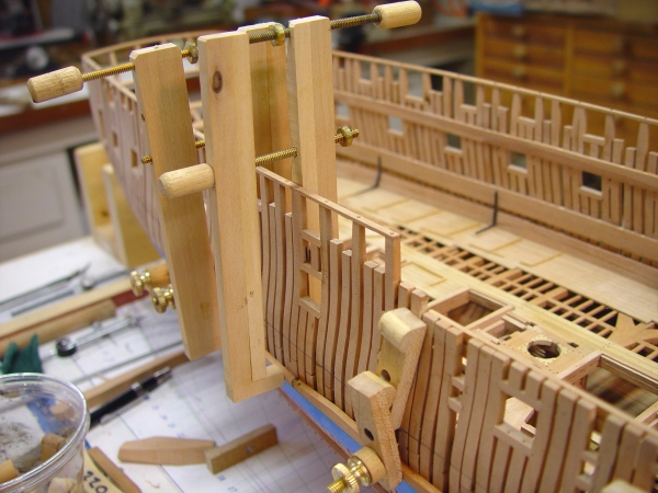
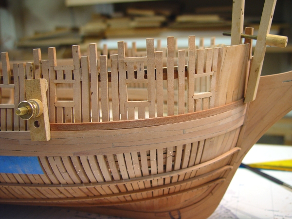
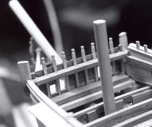
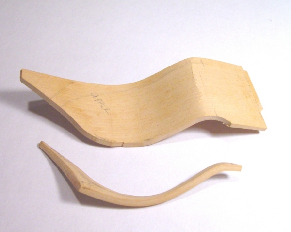
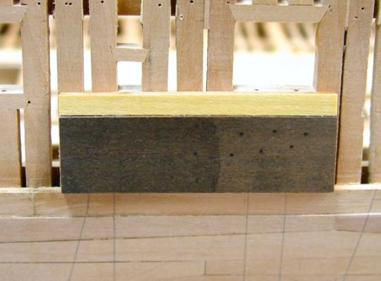
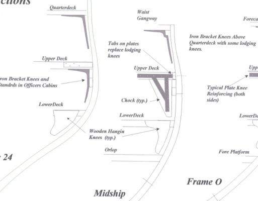
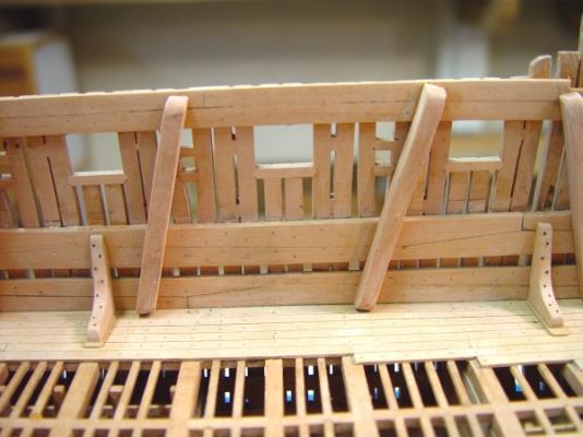
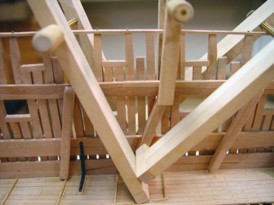
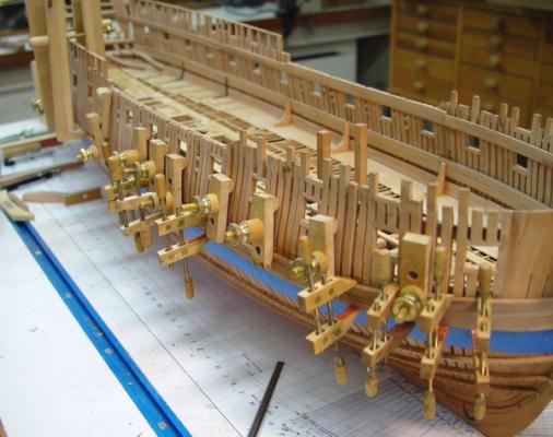
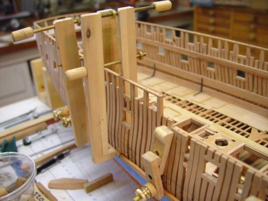
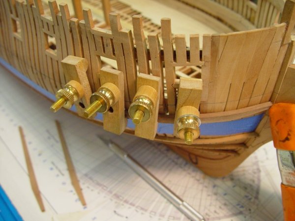
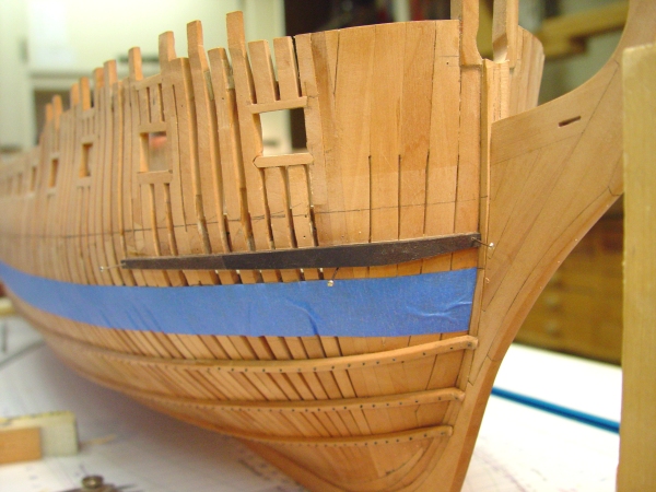
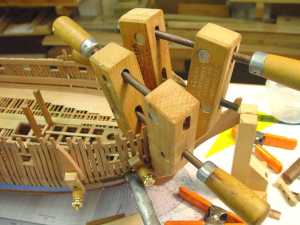
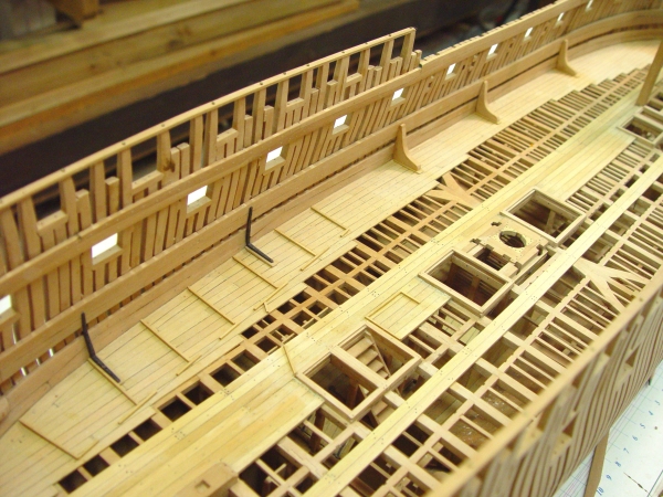
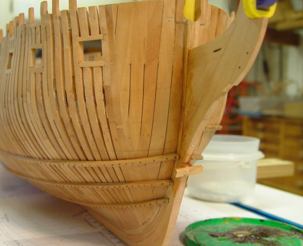
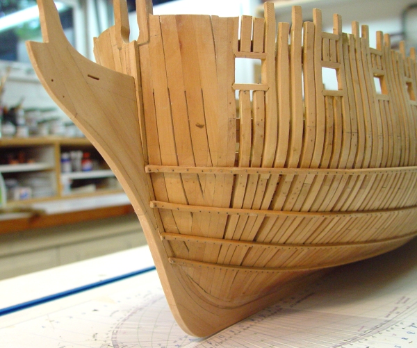
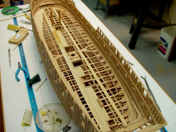
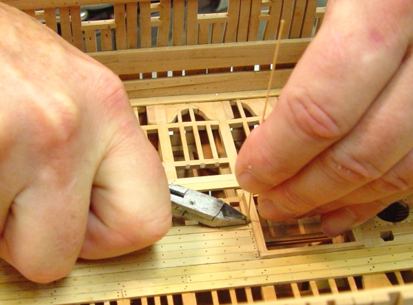
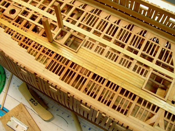
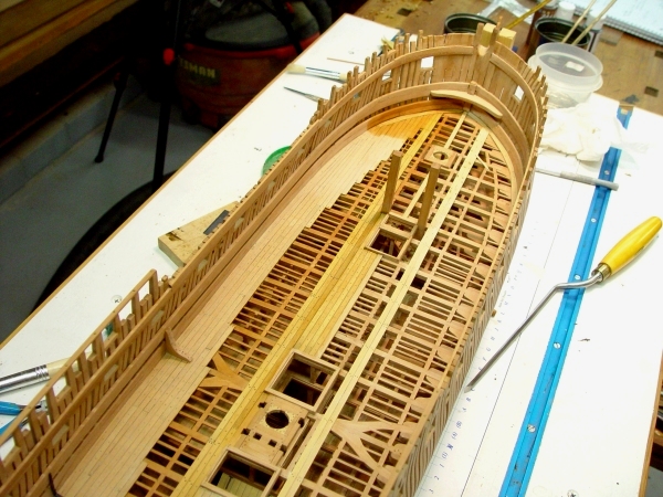
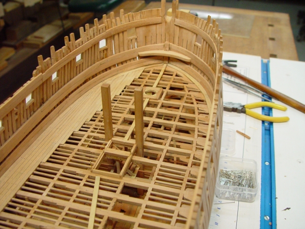
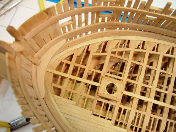
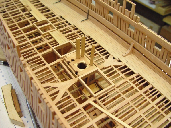
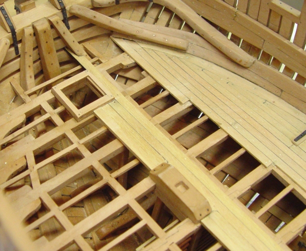
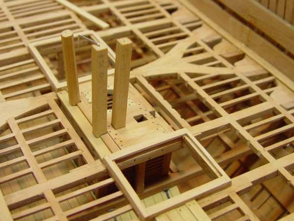
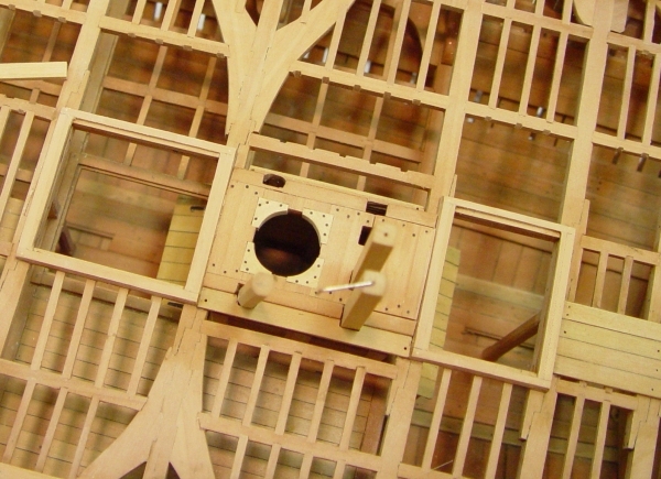
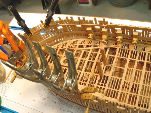
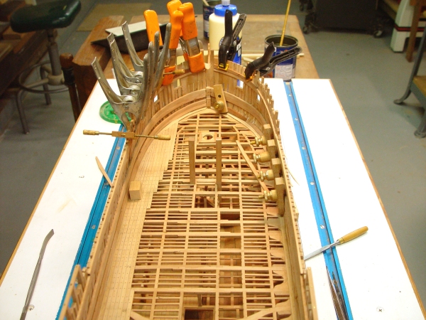
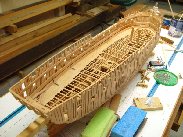
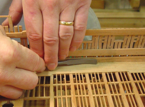
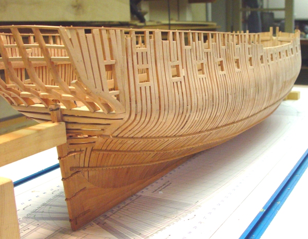
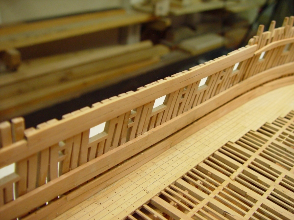
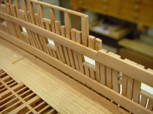
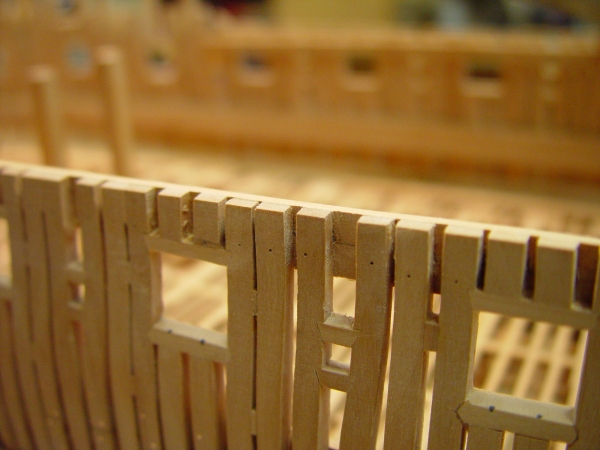
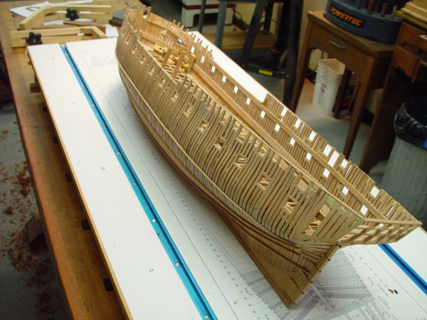
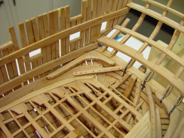
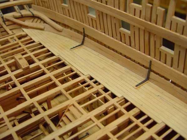
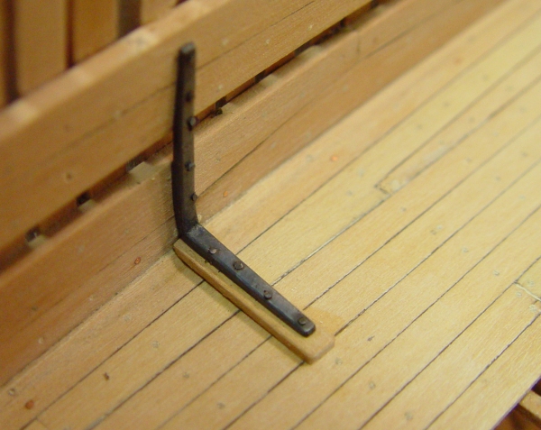
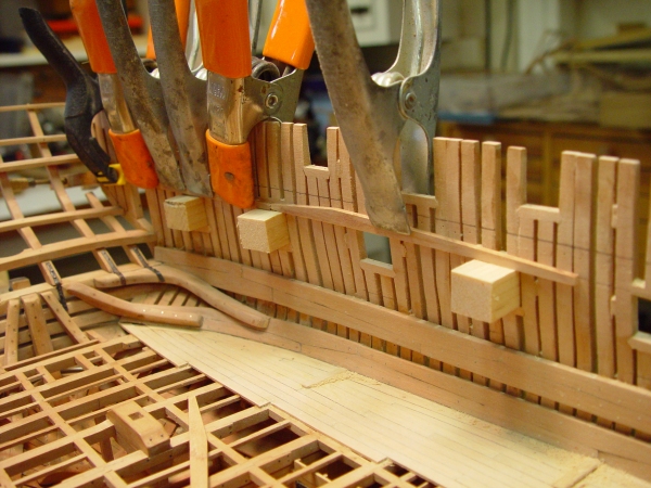
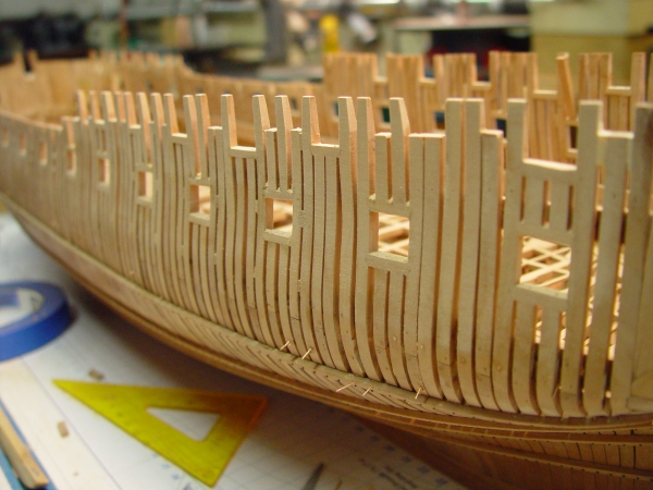
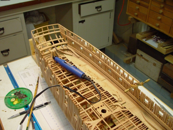
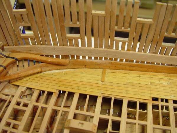
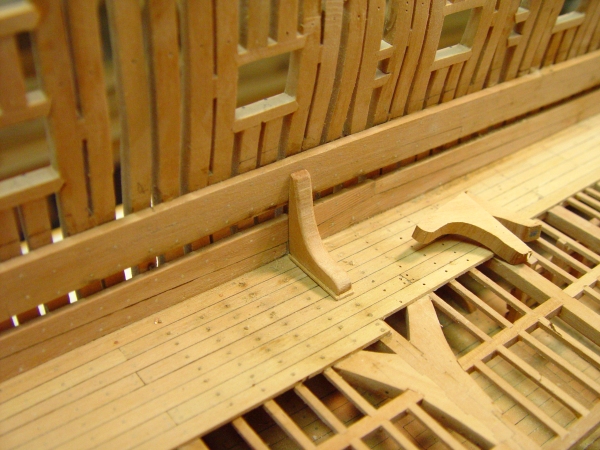
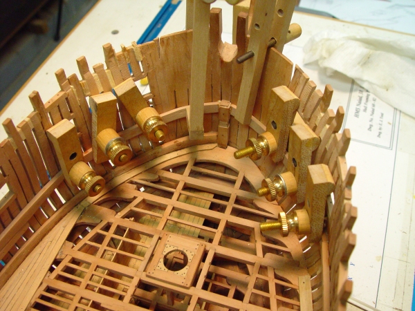
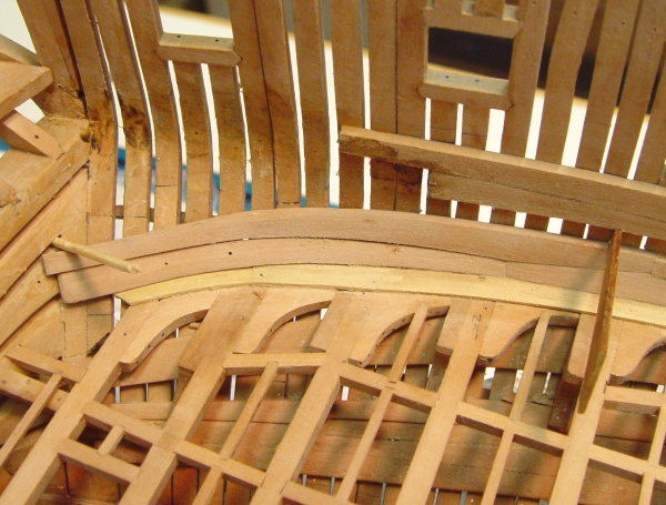
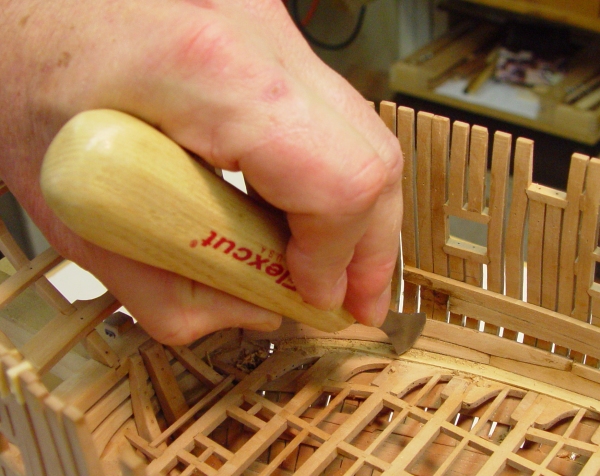
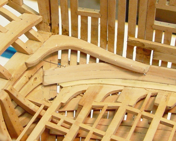
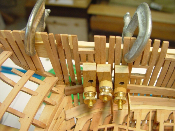
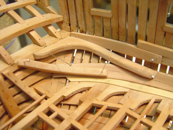
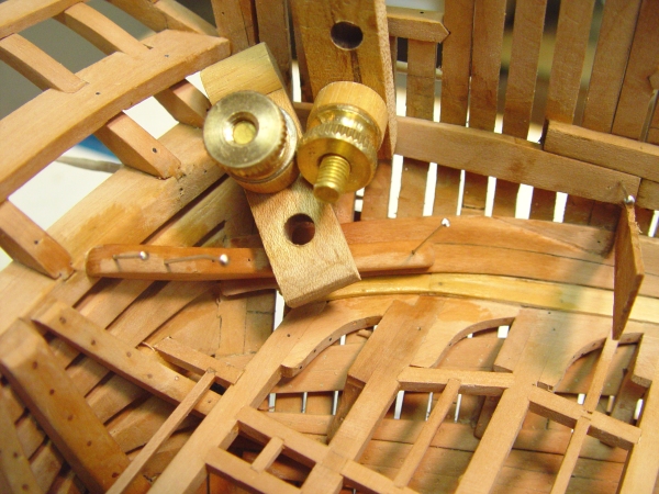
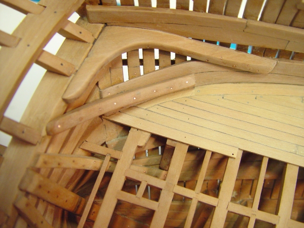
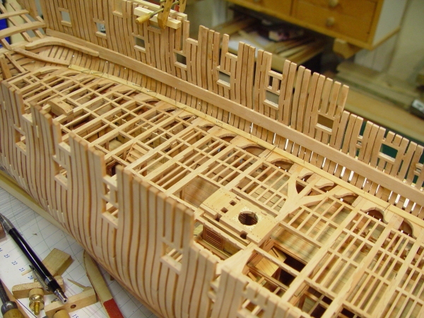
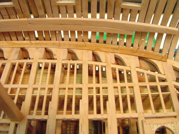
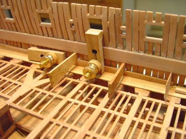
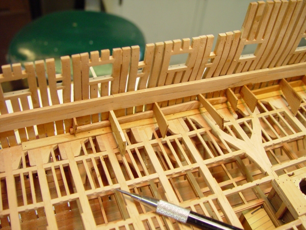
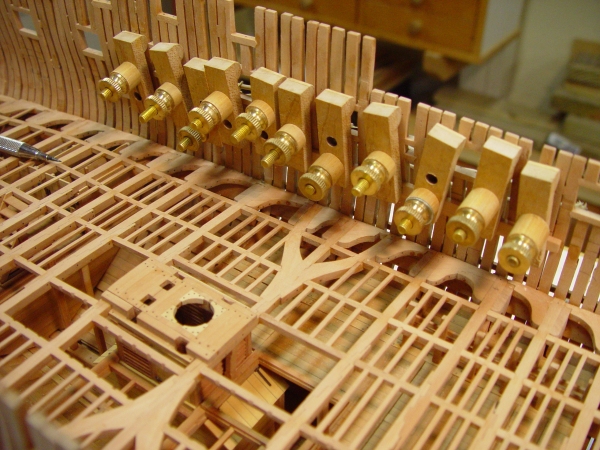
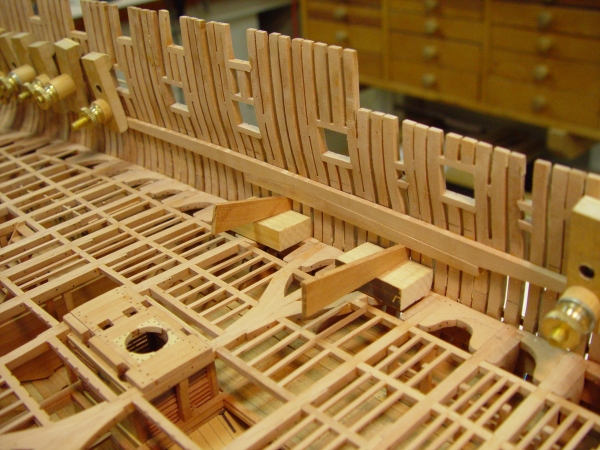
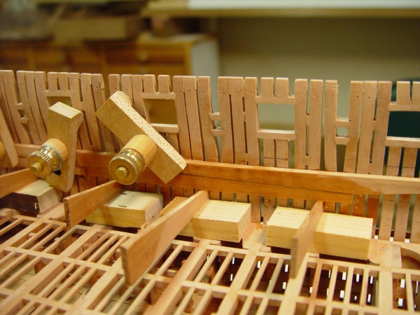
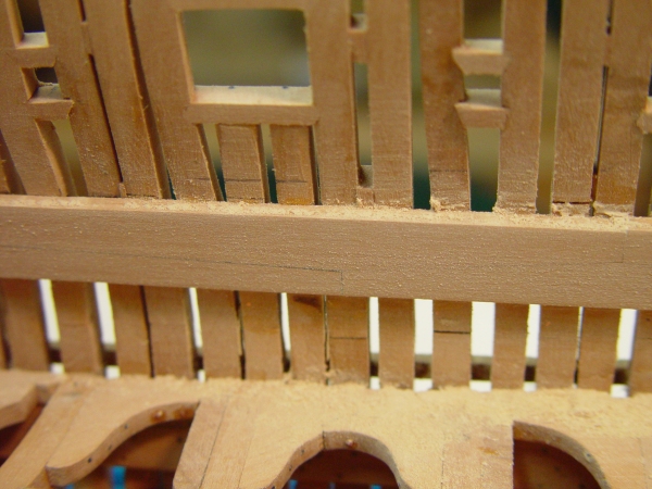
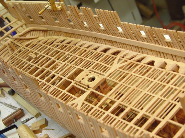
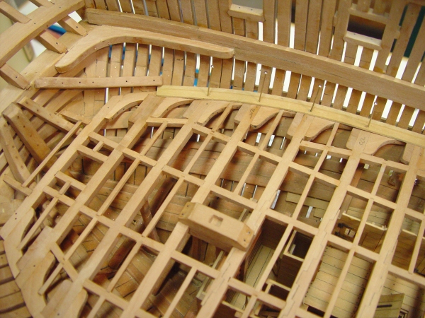
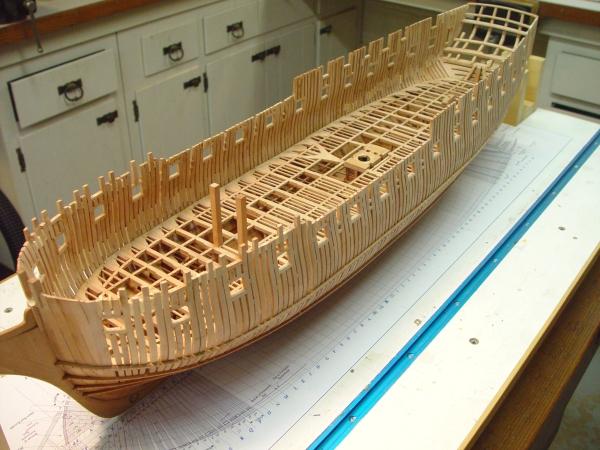
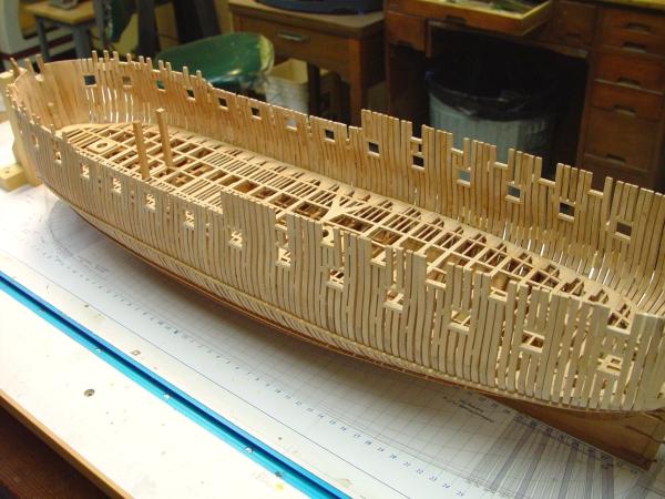
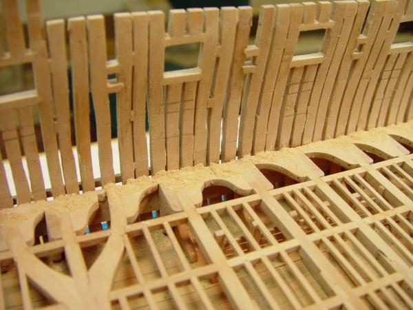
1:60 HMS Naiad 1797 Part 91 – Some Decisions/Top riders Posted 7/26/11 This has been a busy week although there has not been too much progress on the model itself. Two decisions took up a lot of time, but had to be resolved before further work could be done on the wale. With some help from my friends on MSW, I am happy to say both issues have been resolved. The first of these got a fair amount of discussion following my last post. I got some good feedback on the appearance and a lot of information on how to make things black, as well as some good comments on treenails, etc. Most people like a black wale. I have a requirement to be able to see all the structural bolts and treenails. I also like to have a hint of woodgrain. So, first I have decided to use black monofilament for all the fasteners, except for a few copper spirketing bolts at the bottom of the wale. All others, since they are more than 2 feet above the load waterline, would have been iron, per the standard contract. The wale and the black strake will be colored with dilute Speedball acrylic ink, using successive coats to get a shade that is almost black but still shows the fasteners. The ink is pigmented (lampblack) and is therefore permanent, so there will be no lightening over time. I is also impervious to the top coat finishes – wax or maybe oil first for more protection. The following picture shows a sample with the area to the left close to the final color. The yellow plank is European boxwood which will be used for the topside planking. Thanks for all your input on this. The second issue was more technical and required research. Naiad was built at a time when knee timber was becoming very scarce with a heavy building program in progress. In the same month as the Naiad contract was issued, the Admiralty, through the Navy Board issued a directive that iron knees were to be used in all new construction where possible. It is pretty certain that a lot of Naiad’s knees would have been iron, but there is no specific description for her. The standard contracts provide for iron but do not specify what to use where on specific ships. There were several different ways in which iron was being used at the time. To make a long story shor , the following image shows some sections from the Naiad drawings showing the final decision. The lower deck is finished and the knees are all wood, with wood lodging knees. The upper deck will have Roberts type plate knees for all beams forward of the officers cabins. These do not require lodging knees. In the cabins, the hanging knees and the standards will be simple iron brackets, which was done to allow more room in these cubbyholes. There will need to be lodging knees with these and they will be some wood and some iron. Above the upper deck all the knees will be iron brackets as shown above, with some iron lodging knees. Not all these beams had both. All the bolts on all these will be iron. All are above the break line. Back at the shipyard some other tasks managed to get done. The next picture shows the last piece of wale installed around the end of the wing transom. All these end planks were left 3 plus inches beyond the counter timber for later fitting of the planks of the counters. The entire wale is now ready to be marked out and drilled for knee bolts and treenails. There are some additional bolts associated with the work described below as well. The next picture shows two of the top riders installed in the waist area. There were 12 of these large roughly 12” X 12” timbers fayed to the internal planking between the lower deck and the quarterdeck/forecastle level. They are slanted in an irregular way to intersect several frames and they are bolted through these and all the planking. The purpose was to provide some triangular support to the structure, one of several features designed to reduce “hogging,” the drooping of the ends of the ship. The next picture shows more of them. In this picture a rider is being glued in, clamped at each point where it beds on the existing planking – the lower deck spirketing, the upper deck clamps and the quarterdeck clamps. This is done with the improved long reach clamps discussed earlier. They are quite convenient for this. The following picture shows a close up of the clamping. This picture also shows the variation in the angle these are slanted at to hit the right timbers, while avoiding deck beams and ports. This picture also shows one of the iron bracket standards mentioned above in one of the cabins. To make the riders, a strip of 12 inch wood about 2 inches wide was cut to roughly the length of the riders. It was then held against the side to eyeball the shape. It was then sanded to roughly this shape on a drum sander, then refit, sanded again, and again, until it fayed tightly to the planking. A compass was then used to scribe a line along this curve at a width of 12 inches. The timber was then cut off on the scroll saw, finished up and installed. The wide strip was then used to fit the next rider, and so on. The last picture shows another view of these. These needed to be installed at this time, before the upper deck beams, even though it means having to fit planking above that deck in behind them. Waiting for the deck beams and the upper planking would make the shaping much more difficult and would preclude through bolting. The next step is to bolt these and do the starboard side. Ed


-
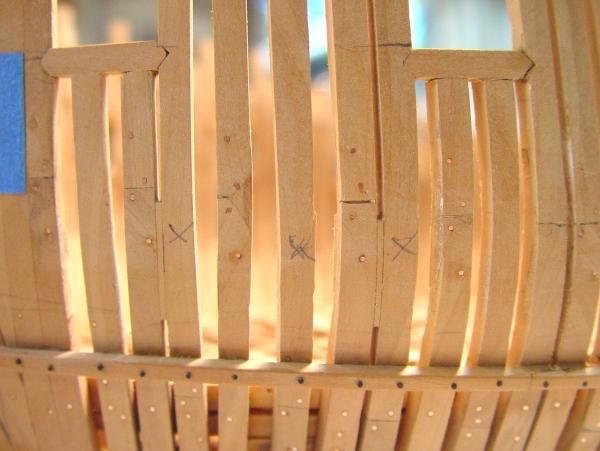
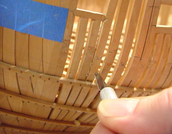
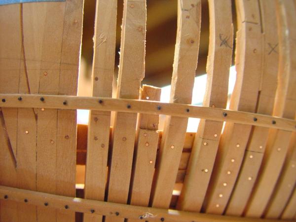
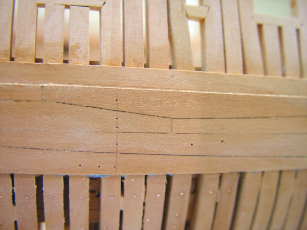
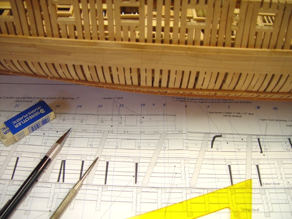
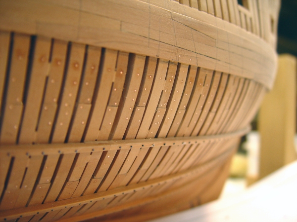
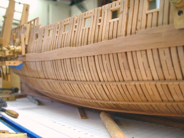
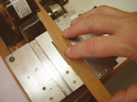
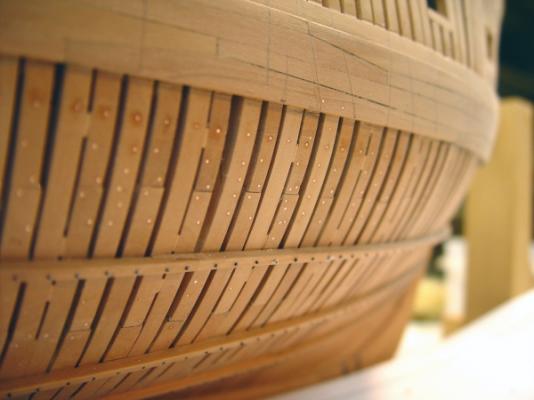
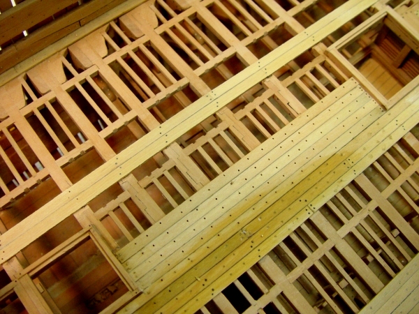
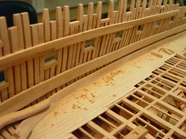
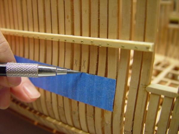
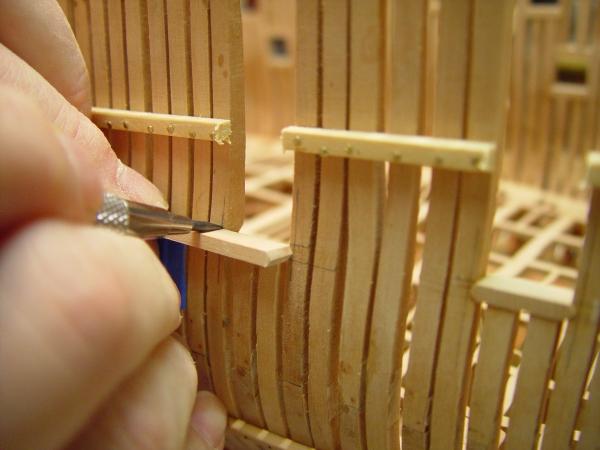
1:60 HMS Naiad 1797 Part 90 – Wale and Bolting Posted 7/21/11 The wale is now completely installed except for the aftermost lower piece, which curves up at the end to bed on the end of the wing transom. Just saving the best for last. The black strake just above the wale is also installed except for one last piece aft. The first picture shows the last piece of upper strake being glued on. The fit of all these top and butt planks has been quite good with very little adjustment needed. I discussed this in the last post. Following are two pictures showing how these were made. First an adequate supply of pear strips were finished to slightly more than the final 6” thickness on the thickness sander. These were then cut to a uniform length of about 25 feet. The short upper faces were then cut on all the pieces as shown above, using a tapered jig, specially sized to the angle required. The other leg was then cut using a second jig cut to the other angle. The next picture shows a finished piece in the cutting position with both jigs. Cutting all these went quite fast – about 20 minutes work. The jigs were made so that one fence setting is used for both cuts. This can be adjusted slightly to yield the right width when the two strakes are assembled. Below is a picture of the finished wale, after a rough sanding. There is a 1-inch lip at the top where the thinner black strake joins. The next step before darkening the wale is the bolting and treenailing. In the above picture the location of all the knees and top riders are being marked on the wale so their boltholes can be drilled. The inboard planking layout has been laid on the board for this purpose. The nxt picture shows some of these hole locations marked out for drilling. In this picture the vertical line of marks is for one of the lower deck standard knees. All the bolts for the lower deck knees will be iron, that is, black. The other four hole marks are for the copper bolts for the lower deck spirketing, which was bolted through the timbers next to the butts of the spirketing planks. The remaining fasteners were treenails. This picture also shows the typical joint lines highlighted with dark glue. In the next picture the lines of holes for the upper deck hanging knees and the top riders are being marked in from the drawing. Except for a few, these upper deck hanging knees will be a chock below the beam with an ironwork strap. This was one type of combined wood iron knee used during this period. All these bolts will of course be iron. I don’t know how many people are interested in all this bolting detail. I committed myself to at least try to get it modeled realistically. Definitive information has been hard to come by. The first question regarding the wale is - was it bolted, treenailed or both? Throughout the 18th century, for planking, including wales, the Brits generally used treenails, the French used bolts. Blaise Olivier makes quite a point of this in his Remarques, a report of his 1737 espionage at British shipyards. Other sources are vague. The most definitive statement is in Dodds and Moore, Building the Wooden Fighting Ship, a current book based on mid-18th Century building of Thunderer, 74. The book lists some sources I have not seen but am pursuing – within the bounds of economic reason. I have 95% decided to use their description – one 1 inch bolt at each butt and the rest tree nailed. An interesting point here and one that effects the overall final appearance is that after laying out the bolts as described above, there will likely be between 250-and 300 bolts through the wale before even counting the butt bolts or the treenails. This is one lot of fasteners. The next picture shows the completion of the bolting below the wale. This had been mostly done earlier, but there were many to add for the lower deck lodging knees, some of the hanging knees, etc. This is now complete and a portion of it is shown below the wale after the first sanding of the frames between the wale and the ribband. Some of the vertical lines for the bolting on the wale can also be seen. Some of these are slanted for the top riders and where dagger knees are installed over the standards. The other question remaining to be addressed is iron vs. copper. Copper was specified below a few feet above the load waterline and in some other places. This puts the lower half of most of the wale in the copper category. In the above picture two copper bolts for the spirketing can be seen in the lower strake. Because of the iron knees, I expect there will only be these few copper bolts in the wale. The rest will be iron. As far as iron bolts vs. treenails, the subject may be academic. Both look about the same after the black finish is applied. I am currently experimenting to see how black I want to make the wale and the black strake. It would be nice to be able to see all these iron bolts and treenails. So, that is the saga on wale fasteners. If anyone would like to add anything or suggest something, now would be a good time. Thanks. Ed


-
1:60 HMS Naiad 1797 Part 89 – Lower Deck – Main Wale cont’d Posted 7/19/11 Finishing up the details of the lower deck continues in parallel with the installation of the main wale. The first picture shows the bolts installed in the wooden standard knees. Pretty much everything from this level up will be bolted with iron. The next picture shows work proceeding from fore to aft on the main wale. This picture shows two of the long jawed clamps which have been modified to increase their strength. This was done by increasing the width of the jaws. They are working very well now and are really fast in this application. I need a few more. Lots of clamps are needed to keep this job moving. Once the work moves toward midship there is no need for pre-bending the strakes and this work goes very quickly. The saw cut top and butt planks have fit extremely well with no adjustment needed before installing. Below is a close view of the long jawed boxwood clamps. The clamps of the type shown in the lower center of this picture are still the workhorses for planking, but with internal planking in place it is sometimes difficult to find a slot for them through to the inside. The one in the bottom of the picture is being backed up by part of another to clamp the strake flat against the frames. Below is a close up of some of the wale near midship after scraping the excess glue off. I had started by blackening the strakes before installing, mainly to help highlight unevenness between planks when sanding, but eventually decided this additional step with its wait time was not necessary. I will do all the blackening when the wale is completely installed, including the black strake. I am using very dark glue between the planks so that the joint will be dark even if the black acrylic shows light on the joints. The blacks of the planks are glued with plain yellow Titebond. I still have some lingering doubts about glue strength loss when pigmented – but so far nothing has come apart, so this is a pretty conservative approach. The joints with dark glue are still much stronger than anything I tried with ebony. In the next picture the forward part of the black strake is being clamped to dry after bending. This plank is left at the length of two planks to make the curve even and to eliminate having to clamp two planks. It will be divided in two before installing. This strake is 5 inches thick and 11 inches wide. This will be blackened like the wale, one coat before nailing and one or more later. There are also quite a few bolts for the knees, etc. They will also need to be installed before finishing. The last picture shows the extent of the wale installed at this time. It has gone remarkably quickly – just a few hours work – discounting drying time on the bending. I did use dry heat on a couple of the bends as my patience waned. Once the wale planks are all installed, the focus will be on nailing and the other bolting so that this side of the hull can be finished up to the level of the wale. I have been searching all my sources for some clear definition of the fasteners to hold the wale, but in vain. I feel certain that there would have been some bolts to go along with the tree nails but can find no clear specification. I would welcome any input on this before forging ahead with an assumption. Thanks in advance. Ed


-
Thanks for these comments. My reposting has slowed a bit in the past week. Its taking more time than I thought, but I will continue. The comments on the rework are appreciated. Deciding to do this is painful, but I agree with Greg that the rework itself is much less painful than thinking about it. The best tool is a very sharp chisel. Guy, I had not thought of included demolition and repair in V2, but I will consider it if there is space. Jan, on the tree nailing I use wood glue – sometimes darkened. I wash glue off with water almost every time it is used. Water will raise grain on wood, but that is easily removed with sanding , steel wool or Scotchbite pads. It does not affect the wood adversely and is actually a good step before finishing, since raising the grain allows it to be sanded off leaving a smother finish. If staining wood with water borne dye or pigment stain is anticipated, wetting first is always recommended. If not done, the dye or stain will raise the grain and when sanded off will often show light speckles. The first wetting usually eliminates any further grain raising on re-wetting. You can test this by wetting an area on fine-sanded (320 grit) piece of wood. When it dries feel for the difference in smoothness. The wetted are will be rougher. Sand it and wet it again. When dry it should be much less rough since the loose grain was all raised the first time. Mark, I probably got the riffler from Contenti. Here is a link to the files page: http://www.contenti.com/products/files.html Now lets see if I can get a few more reposts done. Ed
-
HMS Victory by EdT - FINISHED - 1:96 - POB
EdT replied to EdT's topic in - Build logs for subjects built 1751 - 1800
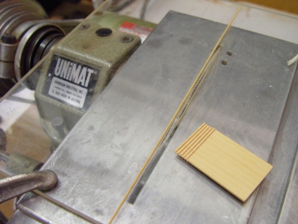
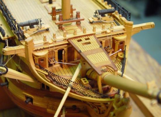
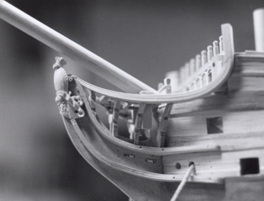
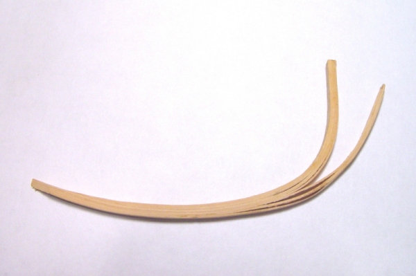
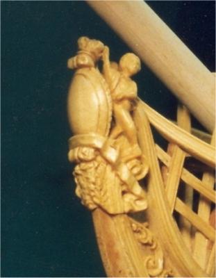
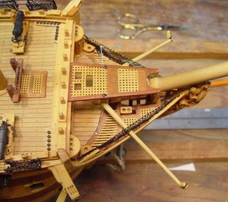
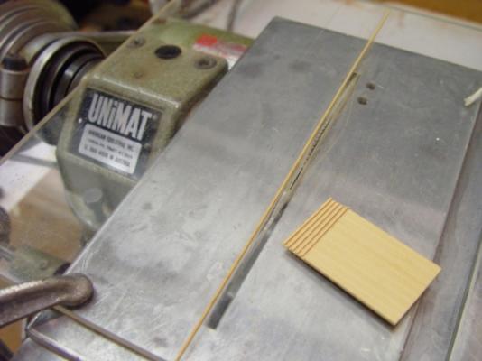
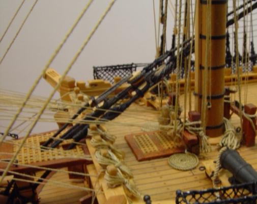
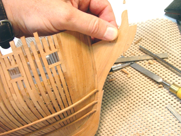
HMS Victory 1:96 Scratchbuild Project Part 7 – The Bow Structure The bow structure is one of the most interesting assemblies of woodwork in the ship, and perhaps one of the most challenging to model. In the picture below, taken later in construction, the various parts of the bow structure can be seen. The topmost of the curved horizontal rails is the “main rail”, which provides a bulwark for the fore face of the cathead, but more importantly is a critical triangular brace for the beakhead. The main rail is supported along its length by four Y-shaped “head timbers” which rest on the gammoning knee (barely visible), which acts as a brace between the stem and the beakhead. The head timbers are faced with a decorative beaded facing. The bottom feet of the head timbers also rest on the “upper cheek”, which fays to the lower plank of the middle wale, then curves inward, forward and upward to fay against the aft side of the beakhead right behind the figurehead. The “lower cheek” is of a similar pattern running from the top plank of the main wale up along the beakhead, ending just at the base of the figurehead. Both these timbers act as horizontal knees for the beakhead. Between the cheeks are heavy planking overlays, surrounding both the hawse holes and the gammoning slots. There is also a curved knee supporting the underside of the cathead and then curving forward along the hull to end just behind one of two lighter weight rails which are supported in notches cut into the head timbers. Finally, we have the figurehead and some leafy scrollwork that trails aft between the cheeks. In addition to the timber structure and figurehead, there is other interesting detail visible in the above picture, including the forecastle timberheads, the decorative arches along the face of the forecastle bulkhead, the “marines walk” with its two vertical supports curved around the bowsprit, the knightheads, pierced for the lower end of the mainstay collar, and, of course, the huge wormed anchor cables, patiently waiting many years for their anchors. The following picture shows a top view of bow structure. This picture, taken much later in the process, shows a different view of some of the details mentioned above. It provides a better picture of the decoration on the forecastle bulkhead and also clearly shows the toilet accommodation for men and the rounded enclosed stalls for the junior officers, all of which derive their name from their location at the “head” of the ship. The top of the marines walk is also interesting with its rectangular openings to take the collars of the mainstay and preventer. As I said above, I found this whole array of detail to be one of the most interesting parts of the ship. Before any modeling of the bow structure could be done, a lot of work was needed to complete the framing of the fore end of the forecastle. My drawings were sadly lacking in details of this and a lot of time was spent looking for better sources of information and translating that into some sketches to base this on. The small, decked area in the above picture is actually at a level above the upper deck in the forecastle and the heavy cat beam across the top of the forecastle bulkhead actually is higher than the forecastle deck. This seemed quite unusual and confusing. The picture below, taken later shows some of this internal structural work. Once this work was done and the basic dimensional information established, the first task was to fashion and install the Y-shaped head timbers mounted on the gammoning knee. These were fairly straightforward except that the notches for the light rails and the points of connection with the main rails had to be carefully laid out. Once that was done the making of the main rails had to be faced. In the full version of part 2 9posted on MSB), I described how to loft the true shape of these rails. Now with the correct pattern in hand the rails needed bending to that shape in European Boxwood. First attempts to get this degree of curvature on this large timber failed – several times. I did not want to cut the rails against a weak cross grain because I wanted the full strength, and also did not want to show weak cross grain in the final model. This problem would also have to be faced in forming the two cheeks, which although having a gentler curve had the additional complication of a wide horizontal triangular shape. The picture below shows these three rails on the port side shortly after their installation. This problem was solved by using laminations of very thin boxwood. First, a six inch piece of 2X4 lumber was cut into two pieces along a line conforming to the curve of the rail with a small blade on a band saw. This would act as the form that would press the wood to the shape the rail. Then boxwood was ripped into very thin strips between 1/32” and 1/64”. In the case of the triangular cheeks these strips were 1½” wide sheets. Then the thin strips were steamed until very pliable. One side of the 2X4 “mold” was clamped in the vise. Strips of wood were then removed from the steaming and immediately given a liberal coating of Titebond glue and layered onto the mold in the vise. The mating part of the mold was then fitted on top and with large clamps the two parts of the mold were pulled together forcing the strips into the shape of the rail. After drying for 2 days, they were released. Below is a picture of a leftover lamination for an upper cheek showing how the cheek was then cut from it. With laminates there is virtually no spring back, so the mold shape will be retained exactly. For some reason this piece was not used, but the lamination is very good, with little evidence of it being a laminate. Once these pieces were scored down with a beaded molding cutter, joints would really be imperceptible. This picture also illustrates the amount of expensive boxwood waste suffered in this process. This cheek, because of its triangular knee shape, required a wide laminate. Below is a picture of a failed delaminated main rail attempt, the result of not enough glue. Once these curved rails were conquered, the work on the bow became easier and I will only describe it briefly since it was pretty straightforward modeling work. The figurehead was carved out of a solid block of boxwood, using a rotary tool with small burrs for roughing out, supplemented with some small gouges and chisels to finish the shape. A picture of the finished carving is shown below. The stance of the two figures took some time and a few failures to work out. Final polishing was done with fine steel wool. If I were to do this again, I would make a mockup first using something like epoxy putty to help fully understand the shapes before diving into the boxwood. The picture below shows the gratings over the bow timbers and in the marines walk. I will describe how these gratings, and many more to follow, were made, I will also discuss the issue of correctly locating the openings in the Marines walk grating for the main stay collars. This picture also shows the areas of straight beam grating, which for some reason was used in part of the surface. This picture also shows the safety netting and some hammock netting, which I will discuss in a later chapter. Gratings were made using the setup shown in the picture below. First, an auxiliary saw table was made from a sheet of 1/8” clear Plexiglas to fit over the Unimat saw table. Then a groove was dadoed into the top surface with a .030” saw blade. A strip of boxwood of the same thickness was force fit into this groove, then trimmed down so that the top of the strip was 1/64th” above the top of the Plexiglas. A slot to take the .030” Unimat blade was cut through the Plexiglas and the table was clamped to the saw table in such a way that the blade projected just 1/64” above the Plexiglas. The table was then adjusted horizontally to give a spacing of exactly .030” between the blade and the strip of wood. A 1” wide blank of 1/32” boxwood was then dadoed with 1/64” deep cuts across its width. First the blank was held against the strip of wood to make the first cut. Then, succeeding cuts were made by placing the previous cut over the strip and making another cut. This was repeated across the length of the strip. A small sample with a few cuts is pictured above. Then, 1/32’ strips were ripped from this piece. To avoid tear out a very high speed and very slow feed should be used with a sharp fine toothed blade. The strips were then interlocked together to form grating. On the real ship grating was not interlocked but merely had cross pieces set in grooves in the support members. Interlocking simplified accurate spacing and also allowed me to avoid using glue. The unglued grating looks crisp and clean and none has ever come apart. A setup like this could be done on any small circular saw, or the grooves could be cut on a milling machine, a process I used later for the flag lockers. I used an angle cut with different spacing to make ladder sides and a similar setup to cut notches in window mullions. The last point I will address in this part was the location of the three rectangular holes in the grating of the marines walk. These openings take the collars of the main stay and the main preventer stay. They must be located very accurately so that when tension is put on these stays no stress is placed on the grating, which would then break under the strain from these very large lines. These openings can be seen in the earlier pictures. The grating in this area is in the shape of a trapezoid and is 3” thick. To locate these holes a dummy mainmast was setup and temporary stays run from the correct height do to their connections under the bow. Using 1/32” stock, a pattern was developed showing spaces needed for the stay collars. These hole locations were set out on an enlarged piece of grating to assure that the openings would clear the stays and also that openings would be bounded by grating bars on all sides. The grating shape was then cut and fit into the opening. The goal here was to avoid having to cut the grating in a haphazard way later. The last picture shows how this worked out on the final model. The stay collars, with their hearts and lashings, actually bend down over the forecastle fife rail. This could not have been foreseen without a mockup. In the next part I will begin to discuss planking and detailing of the upper decks. I have not tried to cover everything in this log but only items I felt would be interesting to a range of modelers. Most of all I would like to reach those less experienced in scratch building, who may well be facing the same dilemmas I faced with Victory. To some, more experienced builders, there may be few revelations here, but if I have glossed over something too lightly, where there may be interest in a better explanation, please let me know and I will try to address it in a future chapter or separately. Cheers, Ed Tosti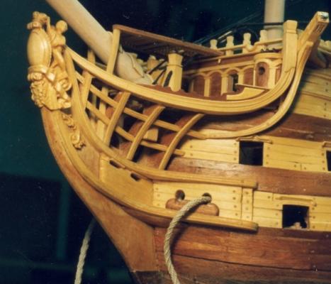


-
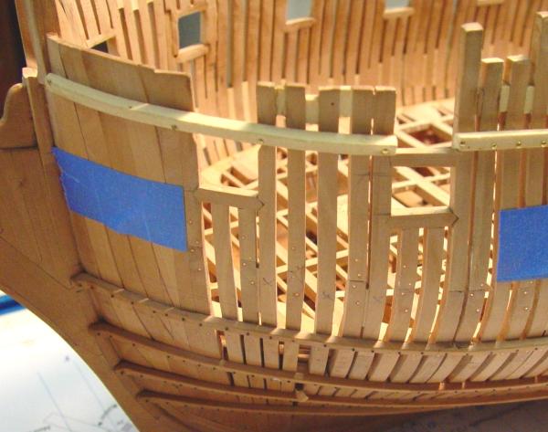
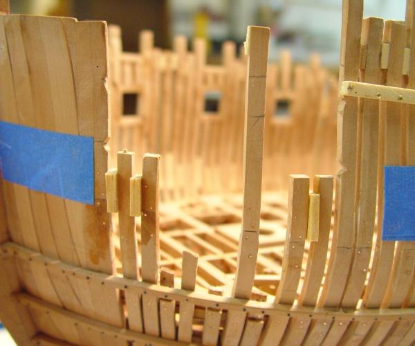
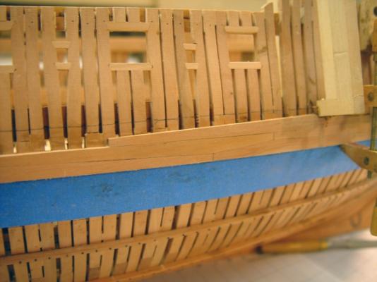
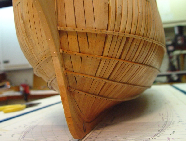
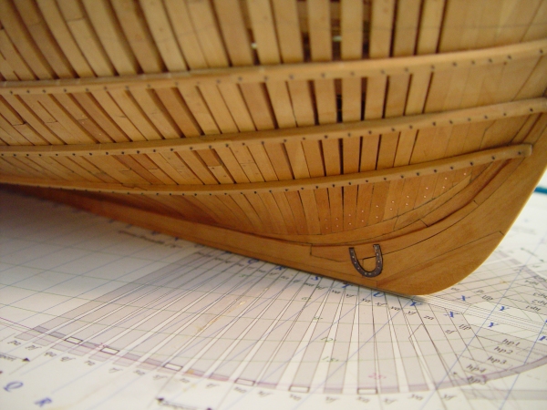
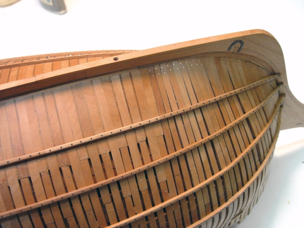
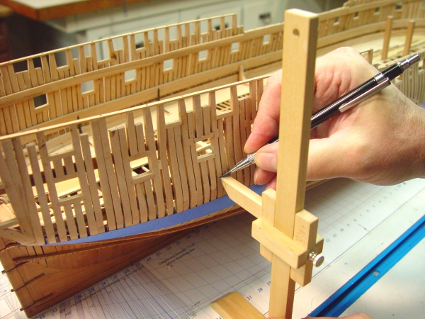
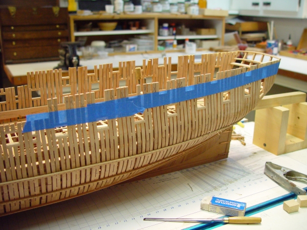
1:60 HMS Naiad 1797Part 88 – Lower Deck – Main Wale It has been over a week since the last post due to another project that had taken over the shipyard, but there has been some progress in a few areas. To finish off the replacement of the stem pieces and the knee of the head described in the last part, some small tasks remained. The picture below shows the new timbers with the bolting for the knee of the head now installed. Having the knee and the forward part of the keel at their correct breadth was a major step forward, in spite of the backward steps needed to get there. This picture also shows one of the new horseshoe plates, which were installed this week. The next picture shows the other one. These plates were done pretty much as before, being inset into the timbers. The shapes are slightly different compliments of Mr. Steel’s drawings, which I did not have when the first ones were done. The next picture is another view of all this. This shows the new keel and false keel sections replaced almost back to the left side of the picture. This was taken after the replaced area was sanded, polished up and given a coat of the wax finish. Late this week I started on the main wale, the first new work in some time on the exterior of the hull. In the next picture the lower edge of the wale has been delineated with blue tape and the upper line is being marked off. The wale consists of four strakes of 6 inch thick planking. It is 3 feet 9 inches wide. There are two bands of top and butt planking with a straight joint line between them The next picture shows the first piece of pear top and butt being clamped in place after boiling and bending to the curve of the hull. The top and butt planks – two can be seen in the picture above – were cut to shape on the circular saw using to tapered ripping jigs made from thin wood to match the two angles needed. These worked well on the interior planking so were used here as well. The pieces are made to a standard length of about 25 feet. Being all the same length makes them easier to fit up, even though on the original the lengths varied slightly – too little to matter. After drying overnight the first piece was installed earlier today and is shown in the next picture. Before gluing, the piece was sanded to smooth it out after the boiled water treatment. This also serves to sand off the raised fibers from the water so that water finishes can be applied without further grain raising. The piece was then given a first blackening coat using diluted acrylic ink, actually diluted liquid artist color. This will seal the surface and provide a base. There will be more sanding done on this and additional coats will be required. The black in the acrylic color is carbon black, so it will never fade. Also, once the acrylic has dried it is insoluble, so it cannot leach into surrounding parts. I would liked to have used ebony for this, but could never find a way to get full strength in the glue joints with it or to get it to bend easily. I finally gave up. It may seem odd to install the upper piece of the bottom band first, but the first piece in the lower strake is quite short and the longer piece is easier to get on the correct line. The pieces below this one will be done next, and then I will begin on the upper strakes, progressing aft with the full width – at least that’s the current plan. The next picture shows two of these next pieces clamped for bending. The four-inch Jorgensen clamps in this picture look huge. They are only needed for their reach. I clearly need some new miniature clamps with a deep throat. I made a few earlier but they do not work well where strong pressure is needed. All the waiting around for pieces to dry has permitted me to continue on the finishing up of the lower deck. The next picture shows recent work done on the port side. The wooden standard knees forward of the cabins have all been installed but still need bolts. Baseboards that will anchor the partitions on this deck are also installed. Against the side are six of the officer’s cabins each with a 26” doorway. They will each also feature a scuttle through the side for ventilation and light. The baseboard slanting to the aft side of the fish room hatch is for the wardroom partition. There will be double doors in this. The wardroom occupied the full width between the cabins from this partition aft. The small partition aft of the main hatch is for the captain’s pantry. It will soon be possible to start on the upper deck beams. Ed
-
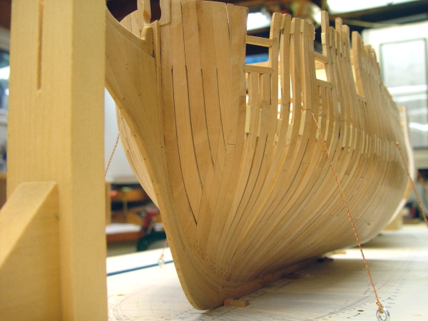
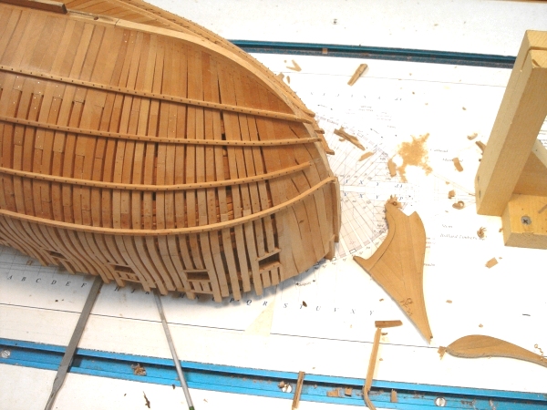
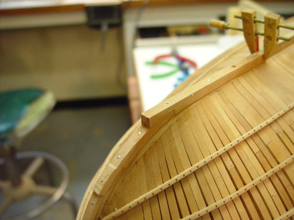
1:60 HMS Naiad 1797 Part 87 – Remedial Work Posted 7/4/11 I have been very grateful for all the wonderful comments I’ve had on the Naiad project. It’s been very flattering. I feel like a degree of realism needs to be injected, to keep me grounded, so….. For a long time now I have wanted to do something about the knee of the head and the lower stem. I have not really been satisfied with the work I did in this area - way back in the beginning of the project. The problem has been a number of minor imperfections, no one of which would lead me to do the remedial work described in this part, but taken together, I decided they warranted some correction. This would be the last opportunity to do it, as I am getting ready to start the external planking on the starboard side. The picture below was taken last fall. Some of the problems are visible in this picture. The keel and the base of the stem are under width. The knee of the head is also too narrow at the base and the forward edge has become too rounded with various sanding steps. Also, the pieces of the upper knee are not quite right. I had copied White, from his book Diana, on the piecing of the knee. Diana was unusual in that she had four transverse head timbers. Naiad and most other frigates had three. This caused the gammoning slot to be in an odd place relative to the knee joints. Also, White has no horizontal gammoning piece on his plan. This can be seen missing just below the standard gammoning knee in the above picture. I had still not gotten around to opening up the slot in this picture. There was also accident damage – gouges - on the lower parts. I felt all this was inconsistent with the general quality of the model, so I decided to replace the knee of the head, the lower stem. This required replacing the first section of the keel and false keel, with the boxing joint and the horseshoe plate. So, the next step was……. I’m not going to show all the gory details – and there were some. I think the above picture gives some idea of what was involved. The old pieces lying about were cut off with a saw; then the joining face to the apron was pared back with chisels and filed clean. I decided to do this without removing the ribbands, which made the work a bit more difficult. One ribband was broken. The next picture shows the forward section of the keel being glued into place with the new boxing joint. By now both pieces of the lower stem were installed. The pins in the picture were cut short and driven all the way in to hold the pieces tight for gluing. They were then pulled out. The forward face of the lower stem still needs finishing off in this picture. In the next picture the gripe area of the knee has been installed and the new upper part of the knee is being fit to the upper stem. In the next picture the lower part of the knee is installed and the upper assembly is being glued. The pin on the scarph of the lower section has a spacer so it can be driven all the way in and later removed without damaging the forward face of the knee. The ship was secured in an aligned position for this step and the final position of the upper knee checked with a triangle for centering and projection. The last picture shows Naiad sporting her new front end. When this point was reached I was both relieved and quite happy. Everything about this new installation is better. Now I can move on to the next stage without regrets over compromises. This build log has started to feel like a clinic on fixing mistakes. I apologize for that. It would be much better to get it right the first time, but…. I guess it’s the final result that matters. Rework can be fun. Ed
-
1:60 HMS Naiad 1797 Part 86 – Lower Deck Binding Strakes 2 In the last part, the method I used to install the binding strakes - the second and third strakes outside the main hatch coamings - was not correct. I had scored down the beams to take the thicker planks. Most of us I believe, now agree that the planks themselves were more likely scored to fit over the beams. Since I had already scored all the beams on both sides, I decided to install the strakes their full length on both sides. This gives the installation the correct appearance. The full lengths of the binding strakes, installed on both sides of the lower deck are shown below. I had not intended to install any planking on the starboard side, but could not leave the (probably) incorrect scores in the beams exposed. This picture shows the full extent of the lower deck planking that will be installed. The next picture shows the planking in the area between the main and fore hatches. In this picture the outside planks toward the bottom of the picture, the port side, have just been treenailed and the area is wet from washing off the glue. The central plank is 5 inches thick and the remaining 4 strakes inside the main hatch coamings are 4 inches thick. All these rest on the beams and ledges, so they step up twice toward the center. The first strake outside the main hatch is 3” thick as is the rest of the deck planking, except for the next two, which are the binding strakes. These are 4” thick and are “let-down” on the beams and ledges to be flush at the top with the 3 inch planking. These were thought to be important structurally, so they are fastened with two short bolts on each beam plus one treenail in each ledge. The boltse are simulated on the model with black monofilament and standout from the tree nails in the above picture. Although these bolts were probably counter bored and covered with wood or caulking on the real ship, I wanted to illustrate the different fasteners as I have generally done, so I made them show as iron. In the next picture, treenails are being installed in the planking butt ends at the main hatch. These are .025 inch bamboo. A slightly oversized hole is drilled, the end of the bamboo rod is dipped in dark glue, inserted in the hole, grabbed with the diagonal cutters, pushed all the way in, then clipped off. A slant cut on the end of the rod is then made with a razor blade and the process repeated – endlessly it seems. Every ten or so, the glue is washed off with clean water on a brush. When dry, the ends are pared off with a crank handled chisel. The deck is then filed flat and sanded. The next picture shows this area after this was done. This area and the open beams outside it toward the bottom of the picture have been given some finish. When this dries it will be somewhat lighter and duller. The binding strakes on the starboard side have only their bolts installed. They still require treenails in between over the non-existent ledges, which were left off to better see the area below. The last picture just shows the current state toward the bow. The waxed area shows quite a contrast with the sanded decking, but this will lighten up when the turpentine evaporates. Areas that still need work done, like the cabin partitions and the standard knees are left unfinished until that is done but I like to get some finish on areas that are complete to protect the wood from staining and also because it gets harder to reach areas later. Thanks for all your input on this question. I wish I had not scored the starboard beams but adding the planks on that side to cover them is an acceptable solution. Ed
-
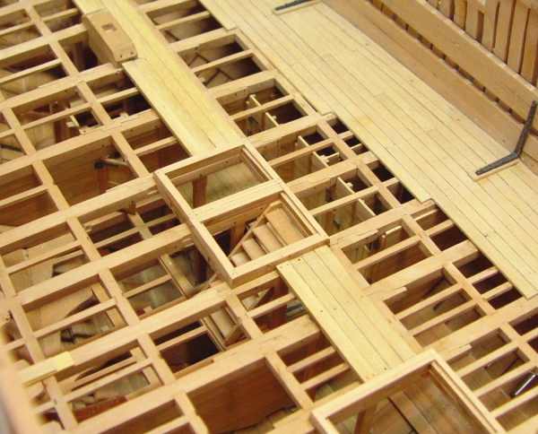
1:60 HMS Naiad 1797 Part 84 – Lower Deck Hatchways Posted 6/26/11 In the last episode the last of the clamps and spirketing was being installed at the bow. As shown in the first picture, this work was completed and the hook between the upper and lower decks has been installed. This picture also shows the coamings and head ledges installed around the fore hatch and the ladder way to the fore platform. The next picture shows a closer view of the bow from above. Its getting harder to see down into the magazine. The heavy 5 inch thick central plank has been installed between hatchways as they are installed. This plank was of heavier thickness to take the pillars, which would help support the upper deck beams. The next picture shows the hatchways around the main mast partners – the main hatch and the aft hatch. It took me some time to get the hang of the joinery on these coamings and head ledges. The coamings run fore and aft, rest on carlings and are rabbeted to take the grating ledges. Their ends are lapped over the ends of the head ledges, which have no rabbet and the lap joint is slanted down like a half dovetail. All four are beveled on the outside faces and will eventually get rounded off on their corners. I wasted some wood before getting these to come out right. The next picture shows the ladderway to the stewards room and the after magazine and the hatchway over the fish room hatch. As these were installed, the planking between them was installed. I mentioned the thick center plank above. The next strakes to the outside of the coamings are 1 inch less but still 1 inch thicker than the 3 inch plank outside the coamings. I still have to decide how to handle the binding strakes also 1 inch thicker but let down into the beams and ledges so they are flat with the rest of thee deck. The next picture shows the center planking toward the stern and the hatch to the bread room. This picture also shows the mizzen step. The last two pictures show the work around the main mast partners, the pump shafts and the hatchways. Once the heavier planking between hatches is installed (on the port side only) the next strake out, a 3 inch plank, will be installed, then some undecided treatment of the binding strake. That will pretty much conclude the decking at this level. I also need to decide which of the hatches on this deck will get gratings. All of the above work still needs treenailing and perhaps some bolts. Ed
-
Thanks for the comments, everyone. Seems like the work in these parts was in another life. I'll be glad to get all the old posts back up and provide some current updates. Ed
-
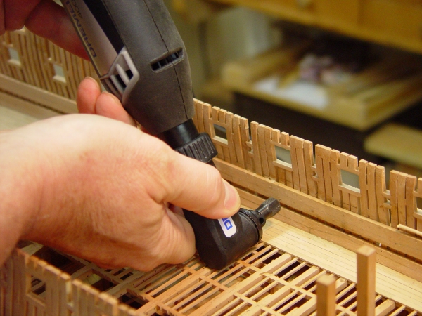
1:60 HMS Naiad 1797 Part 83 – Deck clamps Continued Posted 6/22/11 The deck clamps for the top decks have now been installed and treenailed. This all took quite a long time but now it is done and the frames are now firmly and permanently supported up to the topsides. The pictures below show the last steps of clamps and spirketing installation.. The first picture shows the last pieces being shaped and glued in place at the forward end, which is the most difficult part of this work because of the curves and twists. Below is another view of that which also shows the decking in progress at the forward end. Just a few more short strakes of deck planking are needed at the bow on the starboard side. There will be bands installed in the center, but none installed on the port side Below is a more complete view. This view also shows the temporary rough tree rail on the starboard side installed. The wet area on the upper deck clamp toward the bow is from treenail glue being washed off. The next picture shows a closer view of the treenailing in progress on the side planking and the deck. The treenails are 1.5” (.025”) and are drawn from bamboo. I have been trying out bamboo skewer material for this but have gone back to my previous method using old bamboo garden stakes. These are well dried out and much harder than those made from skewers. They are also somewhat darker. All the ones in this picture are made from skewers and glued in with thinned darkened glue. The picture below shows the heads of the nails being filed down using a #0 flat riffler. Filing seems to be the fastest and best way to level these off. Sanding is much slower and tends to round the planks if not used with a flat board, which is somewhat awkward for this planking. The coarse file cuts the heads off cleanly and also deals with any protruding copper bolt heads. The last two pictures below show the outside of the hull on the starboard side. With the inside bands complete all the pine spacers could be removed and in these pictures they have been, a milestone I have been looking forward to for some time. This side of the hull will be planked from the wale up and that work can now begin at any time. So, there is a lot of work that can now proceed. Internally, the lower deck needs to be fitted out with hatchways, the riders up the to topside can be installed, the cabins can be laid out, the standard knees finished, and probably some other things before starting in on the upper deck structure. Externally, starting the planking would then allow it and the internal structures to be done concurrently. This should facilitate getting the bolting done. There are also the remaining ribbands to install on the port side. So much to do, so little time. Ed


-
1:60 HMS Naiad 1797 Part 82 – Waist Strings, Iron Knees Posted 6/15/11 Progess inside the hull above the lower deck continued this week, but was slowed by other things. Work on the quarterdeck clamps continued on both sides of the hull and in conjunction with this the strings were installed in the waist. These are shown on the port side in the first picture. The strings are roughly the same size as the quarterdeck clamps but are not top and butt and there is a clear break point where they join because although he clamps serve as shelves for the beams, the strings were mainly to support the frames along the waist in an era before the skid beams and gangways were an permanent fixture. The skid beams will rest on clamps that are installed on the face of the strings later. This break is shown in the next picture. The most forward quarterdeck beam, the breast beam, will lodge right up against the end of the string and rest on top of the clamp, which ends at that point. The next picture is a close up of the top of the frames in the waist and the strings from outside the hull. These frames have been trimmed back to their final height just at the top of the strings. The temporary spacers have been removed and the frames in this area are now much sturdier – and aligned. The pinholes in the picture were left from the temporary ribbands, which have been removed. The sheer rail will cover these. With this done, the hull from the waist aft could get one final dose of fairing to bring any errant top timbers into line. Final sanding of the outside of the hull in this area was also begun, but cannot be finished until all the bolts are installed for the knees the upper deck spirketing, etc. the next picture shows the whole hull on this side at this stage. This picture also shows the progress of installing both the quarterdeck clamps and strings on the starboard side and work in progress in the bow area. While this was going on, the wing transom knee and the diagonal knee at the stern were also installed and are shown after the bolts were inserted in the next picture. These now need to be filed off and the knees sanded smooth so the remaining two iron straps can be installed. There is probably going to be a lot of ironwork under the upper deck. It is hard to determine just what was done on the original ship with regard to knees, but at this time iron was definitely replacing wood, so I am thinking about the upper deck hanging knees being done as a combination of wood chocks with iron strapping, a design that was coming into use at this time. The hanging knees and standards in the officers quarters were most certainly iron and the first of these standards, the two on the port side are shown in the next picture. These were made from .062” copper sheet, ripped off on the circular saw, tapered at their ends, rounded off and shaped to fit the sides and deck. They rest on wood “sholes”. They are drilled to receive copper wire bolts, which are driven into the sides and deck – small nails. The copper is blackened with liver of sulfur solution, which I have mentioned before. Any areas exposed by the nailing are touched up with the solution with a small brush, then washed off with water later. The last picture is one of those dreaded closeups of one of these. This picture also shows copper bolts spaced out along the waterway and copper bolts in the spirketing into beams adjacent to the butts of the planks, which was the practice. Everything else here is treenailed. Ed
-
1:60 HMS Naiad 1797 Part 81 – Quarterdeck Clamps Posted 6/8/11 With all the work currently in progress inside the hull, I was becoming concerned about all those top timbers standing up at the side relatively unsupported, so I decided to strengthen them up a bit with the addition of the Quarterdeck clamps. In the first picture a pine batten the width of the two strakes of clamps was cut and fixed in place to mark the top and bottom of the clamps. The lower edge coincides with the tops of the gun ports so I used pieces cut off my no longer needed gun port gauge and inserted them through the ports to serve as a rest for the batten and later the planks themselves. It doesn’t really show in these pictures but the blocks were tilted down on the inside so the back edge of the planks gets down to the top of each port. These will be beveled horizontal over each port later. This batten also served as a gauge when making the top and butt planks. These like the previous ones were cut on the circular saw using the fixed taper guides made for this purpose previously then matched up on the batten to check the overall width. The fence on the saw could then be adjusted slightly if needed. In the next picture the first of the lower strakes is being glued on, resting on top of the blocks. The second piece is in position but has not been glued yet. The Qdeck clamps went on a lot faster than those for the upper deck with all their twists and bends at the ends. The next picture, taken later shows the port clamps mostly installed and just about ready for treenailing. The upper deck clamp, the lower deck spirketing and the decking visible in this picture have all been treenailed. This picture also shows some of the toptimbers cut down to size. The quarterdeck rails will be “berthed up” on the model, so some additional timbers above the number shown on the draft, needed to be full length. Generally, one between each of the quarter deck ports was left long. All the long ones had their sidings beveled as shown on the draft. The debris on the lower deck is from cutting these off. The next picture shows how these were marked for cutting. I am becoming quite enamored with the use of masking tape to lay out lines along the curved hull. Its less trouble than trying to hold a curved batten in place for marking. In this case the points were measured down from the tops of the timbers. After checking and adjusting this top line, it has become the new reference for measurements inside and outside the hull above the lower deck. The ‘X’s’ in the picture designate he timbers that need to be cut off. Those with keen eyesight will notice a break in the line at the forward end. This is because the upper drift rail ends and the timbers forward of that point are somewhat shorter. The next picture shows the result from outside the hull. The Qdeck clamps gave these timbers some support, but not enough, especially for those mounted on the top sill of the ports. A couple of these had already suffered from my leaning into the hull to work. So I decided to install a temporary rough tree rail, much like the rail that now gives the stern timbers protection from me. In this picture the rail has been installed. This took almost no time – less in fact than it takes to fix a broken top timber. It also has the added utility that it can be a drilling template for the final rail. It is nailed down with small brass nails. One of the reasons for adding all this support at this time can be seen on the starboard side over the third gun port from the right. The piece over the second from the right is also a casualty and missing. I have a feeling it now resides somewhere in the dust collection system. Above is another view of all this, including yet another broken toptimber being replaced at the forward end of the installed deck clamp.. My coffee-can-top glue palette and glue brush didn’t make it out of the picture. I’m using yellow glue to attach the planks to the frame because it’s easier to clean off completely off the back side between the timbers. These areas of plank will be visible between frames. The dark glue is being used on the surfaces between the joints. The Wecheer drill, which I have been using for almost all drilling, is also not put away. All these tasks I have been describing provide a break in the treenail making and installing process, which seems to go on and on. There is also the catch-up work to be done on the starboard side. Ed


-
1:60 HMS Naiad 1797 Part 80 –Lower Deck Work Continued Posted 6/6/11 Work has been a bit slow over the past week or so, with some other activities taking precedent, so there have been no posts for over a week. The first picture shows the ironwork being installed at the feet of the counter timbers on the port side. These straps were made from copper sheet, cut into strips on the circular saw and formed around their respective timbers. Holes for bolts were then drilled by hand on the bench after marking in place and center punching. After drilling and polishing the straps were blackened with Liver of Sulfur solution. Copper bolts with heads were formed by peening the stiffened 24 gauge wire. They were then cut off to nail-like lengths blackedened and driven into smaller holes drilled into the timbers. Copper exposed by this process was touched up with the LoS solution, which does not stain the wood. The next picture shows the pieces on this side finished. In the next picture the long task of treenailing the deck and the clamps has begun Treenails are bamboo, about 1.5 inch diameter (.025”). They are inserted with dark glue as a long uncut rod into predrilled holes, then clipped off. Glue was washed off the area with water and when dry the nail heads are filed off and the deck scraped/sanded.. This picture also show the “shole” for the aftermost standard, which being inside one of the officers cabins, will be iron, to give him some more room. The next picture shows some of the deck treenailing and also one of the wood standards being set up outside of the cabins. This will also mounted on a shole. In the next picture holes are being drilled for treenails in the upper deck clamp. Most of these holes were drilled with the small Wecheer rotary tool, which just fits inside the hull, albeit with a slight upward tilt. I have been giving the Dremel rotary tool with the right angle head a trial run for this work and that is shown in the picture. I usually center punch these holes first, then turn the drill off between holes. With this tool I have been using a foot pedal from another tool to start the drill over each hole. Since the drill is set to a lower speed and the foot pedal increases speed proportionally, there is less of the “kick” I had previously experienced with this larger tool. It works well – and fast. In the last picture the forward sections of upper deck clamp are being glued to the timbers in the bow. These were boiled in the usual way, clamped in this way in the bow, left to dry overnight, removed, trimmed a bit, and glued in with the same clamping arrangement. The forward end of the waterway and some of the forward decking can also be seen in this picture. That’s about it for this week – a collection of several small tasks. Ed


-
Hi Mark, Sorry to be a bit late in catching up with your post. For some reason I hadn't gotten a notification and I have been off the site for a few days. Sawdust in the hold - a problem. I could find no way to keep it out. It also tends to stick to the wax finish. I do turn the model upside down and shake it to get out small pieces and debris. To remove the dust I use the blower on my shop-vac, which works pretty well. Be careful not to blow the model away. I also use a long handled artist's bristle brush to loosen the dust if necessary. As a final clean I expect to use a few cans or pressurized air used to cleann electronics. But on the whole the model is pretty clean - and I am finished with sawdust. Ed
-
1:60 HMS Naiad 1797 Part 79 –Transom Knees and Sleepers Posted 5/27/11 Most of the time over the past few days has been spent trying to sort out the fixing of the port wing transom knee and the outer sleeper. Both these pieces need to mate up with the lower deck spirketing. The last picture in Part 78 showed the last piece of lower strake spirketing being clamped in place after boiling. In the first picture below, it has been permanently glued down on the waterway and the frames and the piece above it has been bent from a full top and butt plank and is lying loosely above it held by a wedge and a bit of toothpick. As mentioned previously, the first installation of the transom knee and sleeper was not correct and both have been removed in the above picture. In the next picture the upper plank is glued in and both are getting a scraping to bring their edges flush. The next picture shows the new wing transom configuration based on my best interpretation of Steel, White, et al. Specifications call for this timber to be scarphed down on the spirketting. I had planned to just fay it on top, but after curving the old straight piece to shape and trying it on, it was clear that it wanted to be scarphed into the top strake of spirketing and that’s what is shown in the above picture. The scarph cut into the spirketing is shown below. With this joint the curved transom fits almost perfectly. But before it can be installed, the lower aft strake of upper deck clamp needs to be in place. In the next picture that piece has been given a good boiling and is clamped for drying. Waiting for these pieces to dry out before gluing has added time to the process – a good thing, as it has given me time to think about how this should fit together. attachment=35928:N79 05.jpg] In this picture a pair of c-clamps are holding the frames in line. The planking clamps put pressure on these frames and the backing helps protect them. Also, without any support these can end up bowed outward when the glue holding the planking to them sets. In the next picture all the pieces are in place held by pins. Except for the last plank of the upper deck clamps. This will be fit when all this is glued and will extend back to the counter timber. The next picture shows step one of the fastening of these parts. The lower strake of the clamp is pinned, wedged and glued in place. Ditto for the sleeper, which fays to the top three transoms and the lower strake of spirketing. The last picture shows the finished installation, including the last piece of the upper strake of the clamp at the very top of the picture. The bolts are in the knees but there are more needed on the waterways and spirketing – also tree nailing on the rest. I have settled on all the bolts in this area up to the wing transom being copper and above that, iron, thus the bolts on the feet of the counter timbers are iron (black monofilament). I saw in the contract for another ship the critieria of copper up to 2 ½ feet above water, so I’m generally following that on thrugh hull fastenings. Iron straps will be installed at the foot of each counter timber and the outer two will extend over the transom knee. Now we’ll see if this can be mirrored on the starboard side. At this stage decking has also been installed on this side, enough to allow the officers cabins on this side to be modeled. There will be more pictures of the decking in the next segment. Ed

-
Joss, Looks like progress. Keep in mind that some of the dimensions in Steel are ship specific - although he is not clear about that. I suspect that the example Table for forming bodies may not be specific to your ship. Perhaps thats why things didn't match. The cutting down line heights are most likely ship-specific measurements. Do you have plans for Amphion? If so, the cutting down line is best measured from them, unless you know that Steel's tables are for Amphion. I looked at the table in Steel for a 32 and it does not give the ship name. You,ve marked the plane of the bearding line on your plan in green. The best way to draw it in the sheer plan is by measuing heights up the green line on your body plan for each frame, transferring them to the sheer view and then drawing a curve through them. Hope this helps. Ed
-
1:60 HMS Naiad 1797 Part 78 –Lower Deck Waterways and Spirketing Posted 5/24/11 In Part 77 the Upper Deck Clamps were discussed. The installation of those continues on both sides. In addition the installation of the waterways on the lower deck has begun. The first picture shows the waterways on the port side being installed. Where these curve inwards at the ends the strips were boiled and then pinned to the curved shape in place to dry as shown in the next picture. This picture also shows the concave groove that transitions these from the thickness of the deck, 3 inches, to the full thickness of the waterway, 4 inches. Some of the decking was also begun, a few strakes next to the waterway. The next picture shows the way these are fitted at the aft end of the ship. The next picture shows the first section of spirketing on the port side being installed. The wedges are now being used against the deck clamps to force the lower strake of spirketing down on the waterway. Dark glue is used in this joint. Yellow glue is used on the join with the timbers so it can be cleaned off and not show dark from the outside where there will be no planking. The next picture is another view of this on the starboard side. The wedges are put in first, then the clamps. In some cases the wedges are sufficient. The next picture shows the beginning of the installing of the upper strake. The gap between the clamps and spirketing was filled with ordinary plank. This will not be installed on the model. The last picture shows the aftermost piece of the lower strake of spirketing being fitted after boiling. This is an extreme complex bend in two planes. It got to this final stage in two steps of boiling bending and fitting. It looks very dark in the picture because it is wet, having just been removed from the “boiler” in accordance with the Admiralty spec “while the water is still boiling.” When dry and sanded it will be the same shade as the rest of the pear. It will not be glued here until it has completely dried and shrunk back to its normal size. This picture also shows that the wing transom knee and the sleeper shown installed in Part 77 have been removed after discovering an error in the way the sleeper was installed, and after some further research on the configuration of the wing transom knee. In the last part it was shown straight and fayed to the timbers at the level of the clamps. The new, correct one, will be scarphed on to the upper strake of spirketing per the spec. This requires it to be shaped with a backward s-curve to get it down to the spirketing level. It will be installed after the spirketing on this side is finished. The spirketing, waterways and clamps for both sides are about 75 % installed at this stage, excluding bolts and nails, which will take a fair amount of work to complete. Ed


-
1:60 HMS Naiad 1797 Part 77 –Upper Deck Clamps Posted 5/20/11 To give the upper frame timbers some additional support after taking out the pine spacers I decided to install the upper deck clamps. These are in two strakes, top and butt. The first picture shows the first piece of the upper strake glued to the the frames and clamped in place. The top and butt planks were cut on the circular saw using two specially fitted tapered guides. They are 6 inches thick and 24 feet long, with their breadth set to give the overall breadth of the two strake band when installed. The next picture shows the first of the lower strakes being fit up with wedges to force it up tight to the top strake. In the next picture this has been glued in place, wedged and clamped. The excess glue has also been washed off with water using a damp brush. Ordinary Titebond was used on the frames and a very darkly pigmented Titebond in the joints between planks. The plain Titebond was used on the frames to make cleaning the glue from the outside of the hull between frames easier. In the next picture a #0 flat silversmith’s riffler is being used to level out the strakes. This tool cuts faster than sandpaper and leaves a flatter surface, avoiding rounding. The next picture shows this area after sanding smooth with 120 grit paper on a sanding block. The dark joints in this picture are somewhat obscured by the sanding dust, but they will be more prominent when the wood is polished and finished. This method does give more subtle joint lines than some other methods. The next picture may cause some seasickness. It shows the installed upper deck clamps on the port side, ready for treenails. This picture also shows some other work in the stern area going on in parallel. The wing transom knee has been installed as well as the second sleeper on that side. The next picture shows this closer up. The detail of how these two important timbers mesh with the deck components is a bit tricky here and in the absence of detailed data I made some choices. The wing transom knee is bolted to the frames just under the top strake of the clamp and is made parallel to it. The copper bolts to the frames and to the wing transom are installed but not yet finished off. The iron straps from the two outermost counter timbers will cross over the knee and bolt to it. The second sleeper was left clear to allow the strap on the inner timber to bolt to the transom. The sleeper has no bolts yet. This picture also shows a section of waterway being held in place to dry with pins after boiling and bending it in place. The concave curve where it was “chined” down to the level of the deck planks was machined before bending on the milling machine with a small ball end mill. When this piece is dry the outside edge will be beveled back and fitted to match against the frames in this area. There may need to be an additional short piece to take this further aft. I am still not sure of this detail and how far back the waterway goes. Right now I’m thinking to the aft side of the after fashion piece. When the waterway is in place the two strakes of the spirketing can be installed above it. Lots to do to get both sides caught up to this stage. Ed

-
Don't feel bad, Joss. I'm frightened when I think back to all the iterations I went through to get the Naiad drafts. Ed
-
Joss, if you are referring the the inverted u on the sheer plan, that defines the height of the rising, not the rising wood. The rising is the height of the centers of the floor sweeps above the rising line which is the height of the rising at the dead flat. This is different from the rising wood and I do not believe they are related. This is explained on pp 203-204 in Volume 1. The duplicate terminology is confusing. Ed
-
Hi Joss, I'm not sure I understand your question, specifically, but I would offer some comments that I hope will be helpful and not confusing. The one thing that strikes me is that your sketch shows a discontinuity in the cutting down line, which is probably incorrect. The line of the bottom of the keelson and the tops of the floors, called the cutting down line, was a basic design parameter specified on the Table for Forming the Body. So, it is an independent variable - not dependent on other components. It should be a fair curve along its full length. The heights can be taken off from the profile draft. It terminates at the timber you show as Deadwood 4 and at the stem. The bearding line is not an independent line. It is described by points on a vertical plane offset from the centerline by the breadth of the deadwood - actually half the deadwood breadth. These points are at the intersection of each frame profile with that plane. This applies to the square frames as well. If you draw the bearding line from these points on your the body Plan, the seat for the cant frames will be at the correct height. If you draw the bearding line from the profile you may introduce error. I believe it is preferable to plot The bearding line from heights taken from your CAD body plan at each frame. Just drawing a vertical line outside the centerline to represent the plane and pick of the bearding line heights at each frame. This applies at the fore and aft ends. The terms deadwood and rising wood are essentially interchangeable. They have the same breadth and the rising wood is just a specific part of the deadwood. Of course both are tapered down to the rabbet of the keel. Hopefully this is useful. It helped me in drawing and lofting Naiad. I found that the bearding line taken from the profile differed from the line drawn from the body plan. Good Luck, Ed
-
1:60 HMS Naiad 1797 Part 76 –Port Gun Port Sills Posted 5/18/11 After getting the bow timbers sorted out, the sills could be installed on all the port gun ports for both the upper deck and the quarter deck. Care had to be taken with these because the framing detail will all be visible in the final model. The next two pictures show just a couple of the steps in the process of installing these. This picture shows the height of the lower sill being marked. The tape was used to set this line and make sure it was fair. After this step the bottom of the sill was marked and the mortises cut to receive the sills. The next picture shows a sill being marked for cutting off. With one end of the sill shaped, the other end is being marked to be cut off. The pencil marks for the top and bottom of the sill as well as the line marking the depth of the mortise can be seen in this picture. The next pictures show some of this finished work after the sills had been sanded flush and fair to the sides. These pictures also show the permanent spacers that have been installed between sections of the main frame bends. All but a few of the temporary pine spacers have been removed from this side. Some have been left to support some of the timber stubs, which are only bolted at their lower ends on to upper sills. The next two pictures show the finished port side. A lot of finishing up work was also done, including sanding between the frames to remove remnants of spacers or patterns, installing all the bolts for the sills, and giving the inside and outside a dose of fairing. The next picture shows the tops of the timbers, which, after this fairing, were reduced to their final molded breadth at the top of the side. Without the spacers some of the frames are now self-standing and this increases the risk of breakage. I will probably begin to install the upper and perhaps the quarterdeck clamps to strengthen these timbers. In the next picture the lines of the upper deck clamps have been marked out on the inside of the hull in pencil. The top line is the top of the beams and the next two down are the boundaries of the clamps. These lines were measured from the port sills down. The port sills and the tops of the sides are at the correct height and as mentioned before, the interior measurements will now be referenced from them. A lot of sawdust remains in this picture from the internal fairing, which was done with small rasps following by sandpaper. I have been removing this from the lower decks by inverting the model and blowing it out. Ed


-
1:60 HMS Naiad 1797 Part 75 –Some More Rework Posted 5/10/11 The comments I have received since starting to write about the Naiad model have been very complimentary and often overly generous, so I thought I’d add a another dose of reality to help me from becoming too complacent in the face of all this positive reinforcement. You may recall much earlier in the story, in Part 17, the replacement of the bollard timbers which were poorly made. In this part I will discuss another replacement job. It is in the same area of the ship, which was done back at an earlier level on the learning curve. This has been scheduled to be done for some time. The first picture illustrates the main issue. Three of the timbers between the bridle port and he first gun port are too short. This is due to some careless lofting on my part of the early cant frames and a mistake in trimming them back too early. The three of these marked ‘X’ need to extend up high enough to form timberheads. Another issue is visible in the next picture. In fairing the hull in this area the timber between the first and second ‘X’ marked frames has had its chock exposed due to inaccurate beveling of the joint faces and perhaps misalignment of this frame, so I decided to replace it as well. I could have replaced the other frame in this picture with the gap in the joint face, but where do you stop? All this framing will be visible in the finished model. It can also be seen in this picture that all the pieces to be replaced are fastened to the ribband with bolts and the joints with their lower parts are bolted with copper wire below and at the height of the ribband. This adds some complications.. The first step in the repair is shown below. Here the small razor saw is being used to cut off the first timber above the ribband. It has already had the spacer attaching it on its forward face cut through. The next picture shows the joint below the ribband after removal of the full upper piece, leaving the chock in place. This part of the demolition was done very carefully with small chisels. Holes where the bolts were extracted are visible in this picture. The monofilament ribband bolts were cut off inside using a sharp knife. They are held in too firmly to be extracted from the ribband. The next picture shows all four timbers removed. Some new pine spacers have been glued in for protection against breakage and to maintain alignment. Replacement pieces were then cut out using some new printouts of the patterns, which were revised some time ago to correct their errors. All the Naiad drawings are being revised as the building progresses to fix errors and reflect other changes made during construction. The next picture shows the first of the new timbers being glued in place, before the excess glue was brushed off. Again, temporary soft pine spacers are being used to hold alignment and add strength needed for the fairing process to come. The next picture shows all four new timbers in place. Once the glue on these had set overnight they were given a rough fairing. The lower port sills were then installed to add some strength before the next fairing step. The last two pictures show the reworked area after fairing and some sanding. Fairing was done with 100 grit paper on a rounded soft plastic foam sanding block mostly cross grain. The area was then sanded with 220 grit, with the grain of the timbers. Care was taken not to mar the polished ribband. The three timberheads are roughly shaped in this picture. Everything needs to be re-bolted. Also, work on the next two ports and the cutting down of all the timbers has begun in this picture. Finally, the last picture shows a closer view of the reworked area. With this work done I believe everything on the model is at a consistent standard and I am hopeful that this will have been the last major rework job. Ed