
HOLIDAY DONATION DRIVE - SUPPORT MSW - DO YOUR PART TO KEEP THIS GREAT FORUM GOING! (Only 20 donations so far - C'mon guys!)
×


piratepete007
-
Posts
513 -
Joined
-
Last visited
Content Type
Profiles
Forums
Gallery
Events
Everything posted by piratepete007
-
 Mark, The following figure is from R.C. Anderson where he suggests that the form of spritsail yard bracing (only the starboard shown to keep things 'simple') was typical in English ships around 1690. Just another piece of the jigsaw. Pete
.png.c2307ca5759b9be6c0f4b18e07461076.png)
- 652 replies
-
- 3
-

-
- royal william
- euromodel
- (and 1 more)
-
Its the fine detail that counts - so again well done Mark. Pete
- 652 replies
-
- 2
-
-
- royal william
- euromodel
- (and 1 more)
-
Ken, thanks for the kind words but it is your impressive work (and others) that keeps me stimulated to do more writing. Pete
-
If anybody would like to look at some detailed notes with diagrams and images for the bowsprit rigging on the Royal William, I am happy to pass them on to you - just send me a PM. Pete
-
Thanks Henry.
-
Everything is interesting Henry !!! That wall and crown knot is a fascinating one and I am wondering what the advantage of such a knot was ? Thanks for that informative update. Pete
-
As always Frankie, your comments are so helpful. When building a model ship without sails, the sheet of the spritsail is a line that would be included so logically/ maybe it would be belayed to the yard arm and it (and the pendant) would be belayed along the yard ? Without the sail, it becomes problematic as to where that lead is shown ? Pete
-
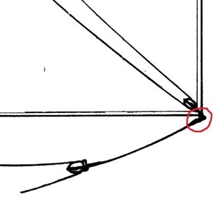
Just out of general interest, I am trying to work out what they did with the sheet (sheet line) when furling the spritsail on a 17C square rigger. The following diagram shows the sheet pendant attached to a bottom clew. What sort of knot would have been used ? From what I can ascertain, when the sail was furled, the sheet and its pendant was temporarily attached further inboard along the yard ? Any help would really be appreciated. Pete
-
Mark, this work of yours is just soooo.... impressive. There are many 'twist and turns' around the bowsprit and you have risen to the challenge. Well done. Pete
- 652 replies
-
- 4
-
-
- royal william
- euromodel
- (and 1 more)
-
Bill, The build is not as intimidating as it would seem. Different techniques and different methods employed by such esteemed Royal William builders as Mark, Ken and Vince, to name just three, serve to illustrate the unique nature of Euromodel kits. These 'kits' are not just the normal run of the mill kits that are readily available. They allow and in fact coerce individuals to be their own creative masters and the choice is there to be as basic or advanced as you like. Be aware that all of their styles and methods have been collated together - and continue to be so - into a set of evolving files available to anybody. In this way, the intimidation you refer to is greatly reduced. Pete
-
Ken, in regards to your above question, I can see why you would put in the lower stave (baton), then the lower segment of ratlines, then the next stave, etc . However, putting in the three staves first would serve to maintain the 'straightness' of the shrouds as you do the ratline rigging as well as dividing the shrouds into three distinct areas for the rigging. A white card placed behind the shroud lines with pre-determined marked spacing would help. Its a case, though. of each to his own. I know that when Mark did his, it was all by eye and good judgement. Pete
-
Thanks to Lou, Mark P and Clifford - your comments are much appreciated and given me a more rounded picture. I think I was getting a little too focused on just the technical side of things as it all started with a photo I received from another builder(see top). Thanks again, Pete Pete
-
Lou - you are not full of it !!! This was just a little diversion from my everyday work by creating a bit of lateral thinking. Your answer is quite logical and I like what you said. The point is that we often gloss over the small things and I was interested to get a range of opinions. Pete
-
Thanks Toni - that makes me think more directly about the stove design itself. Just maybe there was a series of internal baffles to allow heat, smoke, etc out and upwards and diverted downward entry of water away to one side ? Pete
-
Mark, I am receiving a new boat from Euromodel in the next few days and just as an experiment, I will carefully trim down the outside to resemble a carvel build. Will let you know how it goes. By the way, your concept of partial frames looks like a much easier way to go and since it is not a scratch build, why not ? Pete
- 652 replies
-
- 2
-
-
- royal william
- euromodel
- (and 1 more)
-
Thanks for the reference tips Mark. Yes to Mondfeld but not to Frolich which I will need to look at. Pete
-
Now that's really an interesting addendum Mark - thanks for the extra info. It will be useful. Pete
-
Mark, A dramatic change from the supplied plastic resin hull supplied - as you say, it can be worked fairly easily and allows for much individuality in the process. Well done and attention to detail such as the risers, bottom boards, frames, foot stretchers and colour (sorry, 'color' over your way) all are a stand-out. It is an interesting point that the last re-fit of the Royal William occurred in the early part of the 18C and it was also during this time that the Admiralty insisted upon carvel construction instead of clinker. So it seems to me that either style is more than acceptable for this build. Pete
- 652 replies
-
- 2
-
-
- royal william
- euromodel
- (and 1 more)
-
I know this is only a small point to ponder over but from the photos of stove chimneys posted in response to my question, I assume that most kit drawings are a simplification. Logically, most/ all stoves would have needed protection from water entry. Pete
-
Whow Greg, that is one beautiful photo with such incredible detail. Thanks. Pete
-
grsjax and Mark P - thanks for the comments and photos. As always, there is something to learn ! Pete
-
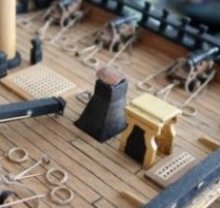
This may be a silly question/ observation. I have often wondered what would happen during a tropical downpour (or other heavy rain) with a relatively large opening down through a chimney to the ship's stove. Was there ever a deflecting cover of some sort over the top opening of the chimney or maybe at the base of the chimney to reduce/ divert what could be a large volume of unwanted water from entering the stove ? The attached image shows what one builder came up with, not from a historical basis but from logic. I have seen some chimneys with a short right-angled section at the top which would work but chimneys are often drawn as simple upright structures. Any comment would be appreciated.
-
To those who may wish to look at a different slant to a Royal William build, have a look at this link which I received from Oliver Lippold. It is not in English but the photos are self explanatory. The build log starts by showing a brilliant carving of the head ornamentation by a friend of his and it is covered in 24 carat gold. Just a fantastic piece of craftsmanship. http://www.wettringer-modellbauforum.de/forum/index.php?page=Thread&threadID=63518&pageNo=1 Pete
- 652 replies
-
- 2
-
-
- royal william
- euromodel
- (and 1 more)
-
For those members intrigued by Mark's last comment regarding deflection of the foremast stay, they might be interested to know that through a mutual cooperation between Mark, Vince, Ken and myself, I am writing a collection of detailed files describing how the Royal William could be built [the files are freely available to anybody to download]. I have the greatest respect for these members who are currently showing a wealth of different skills in building the same ship and who allow me to collate what they are posting. The following two images hopefully illustrate the problem in creating a suitable tension in the sprit topmast backstay that does not interfere too much with the alignment of the fore topmast stay. Pete
.png.d2ed4473a46a3b22d280edfe40499450.png)
.png.0eac7f31f0dba4884ffc09517a609cd0.png)
- 652 replies
-
- 8
-
-
- royal william
- euromodel
- (and 1 more)
-
Mark, You HAVE been busy. The build is 'like whow' and now a mass of intricacies that we all dream of in a ship. Well done. I like your sprit topmast backstay rigging (with the ten blocks) where it was so important to have less tension in that than the other stays, backstays and shrouds (to have the same tension is likely to cause a deflection in the fore topmast stay). Must have been a little tricky. Pete
- 652 replies
-
- 2
-
-
- royal william
- euromodel
- (and 1 more)