
MORE HANDBOOKS ARE ON THEIR WAY! We will let you know when they get here.
×


piratepete007
-
Posts
513 -
Joined
-
Last visited
Content Type
Profiles
Forums
Gallery
Events
Everything posted by piratepete007
-
 Out of interest and adding to jbshan's comments, the following diagram shows the hammock layout with colour coding on the lower deck of 'Bedford' (1775), a 70 gun Third Rate, two decker. It is thought that the hammocks indicated in blue represent the sailors; those in red, the marines.[the diagram and text comes from the Picture Library of the Royal Museums Greenwich and is subject to copyright].
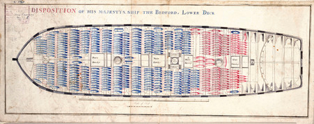
-
Vince - a very sensible comment about the weathering of those barrels. The guns look well finished and good luck with their rigging. It's amazing how often builders side-step this important feature and just install them 'rig-less' (if there is such a word). Pete
- 593 replies
-
- 5
-

-
- royal william
- euromodels
- (and 1 more)
-
Hello Folks, I have found considerable information about painting & decorating hulls over time and in different countries but very little about the masts themselves. A search of the MSW postings revealed little but maybe I missed it. My feeling is that in most cases, the masts were left in their natural state and only varnished or oiled to protect them. The common exception seemed to be with the hounds, tops, crosstrees, mast caps and mast 'doubling' where black paint was commonly used. Without some useful references, I feel 'all at sea' on this aspect. Pete
- 1 reply
-
- 1
-
-
Maybe time for a small pause in this fantastic construction - however, I doubt whether you will take that pause Mark. I agree with Greg that this is indeed a phenomenal benchmark for a completed hull of the Royal William. Not for anyone to follow necessarily in its absolute detail but Mark has shown what could be done and I would like to think that others that are in the process of building their own Royal William will be inspired to 'carve out' their own presentation. There is so much freedom within this Euromodel build to create an individualistic approach. This ship is becoming a beauty to behold (to coin a phrase). Congratulations Mark. Pete
- 652 replies
-
- 2
-
-
- royal william
- euromodel
- (and 1 more)
-
We tend to judge the popularity of a kit by the number of different build logs on MSW. How fantastic to see the photos from Bill of his wonderful work on the Royal William shown above even though he has not set up his own build log. I for one would love to see some more of his photos in the future. I suspect we could all learn a few tricks from his obvious depth of expertise. Pete
- 652 replies
-
- 3
-
-
- royal william
- euromodel
- (and 1 more)
-
Many thanks, Allan and Erik
-
Erik - Any chance of some more information on this order because the last refit for the Royal William was between 1714 - 1719 and I am wondering whether there was a change to the wales during this period or perhaps an intended change that did not occur ? Pete
-
What is the most EPIC kit available???
piratepete007 replied to Rossi46's topic in Wood ship model kits
I agree with everybody. Many of the kits out there are 'stunning' or 'beautiful' or 'majestic' or whatever ..... but they are just kits. To turn a kit into an 'epic' you will certainly need to add extra detail. My advice to you is to seek out a kit that has extensive plans that go beyond what is supplied in the kit material and do your research. Pete -
Royal William Kit by Vince P. - Euromodel - 1:70
piratepete007 replied to pirozzi's topic in Wood ship model kits
Euromodel has produced a range of kits for ships that existed during the 17C - 18C and each model portrays a significant amount of history. For example, the Royal William, for its age, is exceptional in showing a continuous waist rail along the complete length of the ship from cathead to stern, albeit at different levels but joined by ornamental hances.... but I dare not deviate. For a ship initially launched in 1650, there are many special features to appreciate. It concerns me that again there is a level of criticism being directed at a family business and it looks like a case of 'here we go again' !!!! BUT, yes, there are things that could always be improved upon. Different people will see negatives in various ways. Who am I ? Just a guy who enjoys the challenge of building Euromodel ships BUT having no commercial or financial link with the company concerned. I have nothing to gain by answering the current criticisms. It just annoys me that there is so much to gain from building their kits which are just so different to the standard kits that replicate what is shown. There are just so many positives to gain from building the Royal William and I believe these outweigh the negatives. The comments made today in a sense portray what the Euromodel philosophy is all about. You CAN build a fine ship model from the kit supplied but the plans supplied are of such intricate detail that the builder is drawn into the purchasing of extra material. That in turn reflects upon the skill of the builder. So if you wish to move on from the normal style of kit- build replication, then this style of kit offers that challenge without moving on to the pure scratch build. Keep in mind that all that extra expense is not necessary but having said that, it does allow for a far better build. On this web site there is an incredible example of a rapid but detailed and very thorough build shown in Mark Tieden's post. Simply type in 'Euromodel Royal William'. Mark has taken this build to a very high level. I do not agree with the number of comments about a lack of instructions - there are detailed, very detailed, instructions on how the Royal William could be built. Mark's post certainly shows that and for the last few years (maybe 4-5 years), I have been posting continuous updates on the Euromodel website. So the instructions are there to be used, even if I have only got up to the completion of the masts. The most enjoyable part of my current work with the Royal William is the strong interactive cooperation I have with Mark as we bounce ideas off each other. Regarding other comments ... 1. the poor fitting of the laser cut bulkheads. It is possible to have poor fittings but I suspect this has more to do with humidity of the air at that time. Personally, this has never been an issue for me but if a bit of shimming is necessary, so be it. In my posting on the Euromodel web site for interpretive files (RW.01), I wrote ... "The fifteen transverse pre-cut ‘bulkheads’ were slotted into the false keel as a dry run to determine the fitting of joints. A significant number of the cross-joints were a loose fit and some packing was needed." In this area, I went to great pains to add in extra timber between the bulkheads to absolutely ensure their correct alignment with each other and to give greater strength to the overall hull. So if there was a bit of movement in those bulkhead slots, it actually helped ! 2.the poor filigree piece on the stern. Mark made an excellent job of improving upon this little piece so it can be improved upon without any additional expense. Lack of rigols - again, Mark has made these without any apparent extra expense ... and do not lose sight of the fact that these are but one of the extra things that could be added. I see many other kits without these being shown at all. 3. the poor hinge quality. This is a significanr point here but the interesting thing here is that most port lids are fixed in an open position and very few hinges are to be really observed. I plan to produce my own hinges. The only downside to the alternative photo-etched hinges is their very thin nature so they can only be cosmetic (make sure that alternative arrangements are made like pinning the lids to the hull or the stability of the lids will be flimsy). Now I am more than happy to work with any person building, or contemplating building, this ship. This is what I enjoy doing. So let's work together, talk to me (and others like Mark, Vince and Keith), build this ship and get mutual satisfaction from the experience. It is possible to work around the perceived problems that exist. Now excuse me while I go and look at that garboard ! Pete -
Mark, Your last post is detailed and explains everything. I now have a much better appreciation of the carriage rigging. Thanks. Pete
- 16 replies
-
- 4
-
-
- Gun tackle
- Triton cross-section
- (and 2 more)
-
I have carefully read all of the above comments - which I found particularly interesting - but there is an ambiguity that needs to be clarified (for me at least). The thread centered on the port tackle but was this replaced by the tackle used for traversing the gun through an arc OR did both the port tackle AND the traversing tackle co-exist ? The eye bolts on the carriage side seem to support the latter ? Pete
- 16 replies
-
- 3
-
-
- Gun tackle
- Triton cross-section
- (and 2 more)
-
JRMc - thanks for that hint. Will have a look ! Pete
-
Special message to 'dafi' who made a post today. I tried sending you a PM but I received a message saying that was not possible. Can you send me a PM so I can respond ? Just need a little assistance from you. Pete
-
Thanks Jan and Dirk - I will take both those suggestions on board ! Pete
-
Chuck from Syren is doing a great thing with the gun port lid straps and I will probably order some. But I am stubborn enough to want to produce my own straps, I guess from brass. So, in spite of Antony's response, has anybody got a method that they use ? Pete
-
Hi Antony, Silly me - 1:75. Thanks for that info and I will have a look at that. Regards, Pete
-
Is there anybody out there who can give me some tips on making gun port lid hinges ? I have searched high and low on this website but cannot find much to help me. Those commercially available are pretty limited in their offering. I guess I will have to work with brass shim but there have to be a few tricks in cutting along the edges ? Pete
-
... and like others with their Royal William builds, an amazing amount of detail. Well done Vince. Pete
- 593 replies
-
- 3
-
-
- royal william
- euromodels
- (and 1 more)
-
Whow Mark !!! The fine detail in your work really sets this build up on a pedestal and contains detail often overlooked - like the ogee and arched rigols and especially the addition of extra timber pieces onto the port lids. That latter point is exactly how the lids were produced in order to produce a uniform surface when the lids were shut (and evident in one of the above photos). With regards to the hinge straps, another nice touch but for others reading this, the usual method was to use some thin brass sheeting - so no problems there creating the straps. The ornamental chesstree pieces (for the main tack) are a nice touch, especially when that style was typical on the this ship when it started out in life as the Prince, launched in 1670. Pete
- 652 replies
-
- 3
-
-
- royal william
- euromodel
- (and 1 more)
-
JBITW, This diagram may be more useful. Pete
-
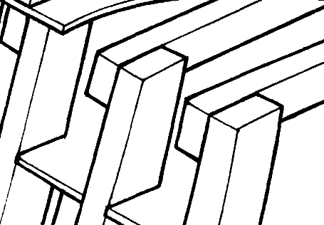
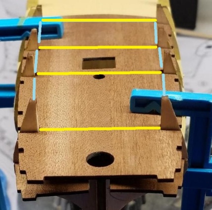
Hi JBITW, Firstly, regarding those bow filler blocks - definitely the lower half and yes the upper half. Lets be candid about all of this. So many people get hung up about cannons (guns) and their positioning. The cannons do NOT all have to be projecting out through the gun ports and in my opinion, there is nothing wrong by cheating and having a few lids closed. Cannons technically were only pushed forward in preparedness for battle. I am a little confused about the support for the quarter deck you have clamped on in the above photos. It appears - but I may be wrong - to be only supported at each side of the ship without underlying beams athwartships (across the ship). In the attached edited photo, the yellow lines represent some scrap timber lengths acting as beams but with a suitable camber (ie. curvature) glued onto the aft side of each frame. These lines are misleading as they should stretch right across the ship and behind the frames. The blue lines represent spacer blocks between the frames that serve to hold the top ends of the frames in the correct alignment as well as supporting the deck. That way, you have a near-perfect supporting base for the thin plywood deck. Under those conditions, you could plank off the ship but I would get the deck fixed in position and plank at a later stage. Hope that helps, Pete
-
Hey Pat, You are a great source of information. Thanks for all that and I will pursue it further. Regards, Pete
-
Just saw this thread about the gun port lids. Now I just picked up on the use of illuminators (and scuttles, but that's another issue). Carr Laughton talks about them being fitted in 1809 and describes them as glass bull's-eyes. Can anybody shed some light (pardon my pun) on these devices ? Would be interested to see some actual images rather than an artistic drawing. Pete
-
Mike, That Goodwin text is one of my essential books when referencing. An excellent guide. Pete
-
My sixteen-year old grand daughter comes here after school every night of the week and patiently listens to a new facet about shipbuilding. So I was delighted when we went to visit an old clipper recently and she started talking about the garboard strake. The tour guide's eyes almost popped right out ! May I make a suggestion ? I notice the empty space between Frame 1 and the plywood keel at the bow. This is an area where planks (sorry, strakes) undergo a fair amount of twisting/ curving. It will make life a little easier if this was filled in with some filler blocks. Any timber will do but in doing so, it allows you to get a better appreciation of the profile and it allows the planking to be done a little easier. Now, I know there is a gun in the upper part of this area but a little bit of carving out an area for this would do the trick. Anyway, just a thought. Pete