HOLIDAY DONATION DRIVE - SUPPORT MSW - DO YOUR PART TO KEEP THIS GREAT FORUM GOING! (Only 20 donations so far - C'mon guys!)
×

piratepete007
-
Posts
513 -
Joined
-
Last visited
Content Type
Profiles
Forums
Gallery
Events
Everything posted by piratepete007
-
 Good update Robert and thanks for the info. After reading the above quotation, I was reminded about this argument that pops up from time to time. As a chemist, I appreciate the points being made but believe the ammonia reaction is extremely slow and soaking for a week or two will only partially change the lignin structure without any overall long-term damage. My approach is to lift the strips out of the aqueous ammonia after a week and to then place them into a previously contoured timber press that has curves slightly stronger than that required. There they sit for a few weeks - although I have used a warm oven to accelerate the process. I went and checked on ship of mine that had had some curves created by the above process approx. 10 years ago and everything looks fine. Using ammonia solution on wales and rails yes but not for general planking. Pete
 -
Robert - when you say 'ammonia', what were you actually using ? I had a similar piece of timber soaking (and forgotten about) for approx. 12 months. When I pulled it out of the ammonia solution that I was using, I formed a rough loop and tied the crossed-over ends like a bow !
-
Chuck, You have made much progress since your last post and things are looking impressive. Yes, the gun port cutting out is slow and laborious but the end result is worth while. From your photos, do I assume that the galleries and side galleries are not fixed in position? If that is so, remember to align the side galleries with the sheer line of the ship. Pete
-
I came across this comment today and coincidentally on this same day I heard that Euromodel are actually back in production. However, they are more than a little frustrated waiting for a few components that are being held up by supply restriction/problems due to the current health issues. Pete
-
Adding to what Mark said, in my build of this ship, the three ports towards the bow were 36 mm centre-centre, one at the stern was only 33 mm from the next port forward with the majority between being 35 mm. Overall, this worked out to be 34.7 mm. Visually, there appeared to be little difference between the gunport separations. I continue watching with interest Mark ! Pete
-
Hi Chuck, I wrote the pdf's that K referred to and I see you have printed them off. Good luck with your RW build and just remember that this is not a typical run-of-the-mill kit. The drawings contain a large amount of detail, some of which could be ignored and it is really up to you as to how much of that you include. More than happy to receive any queries (PM's) and I have drawn up a comfortable chair to follow your progress.
-
After Ponto last posted something on his build of the Euromodel La Renommee virtually one year ago, it is interesting to read these recent posts that have started popping up. The kit may not be without a few critics questioning a few points of historical accuracy but Ponto's comment … "I was only interested what a beauty she is as depicted by Euromodel. It is always up to the builder to bring the contents of the kit to life". Ponto has certainly created a fantastic partial build of the La Renommee as it is depicted in the Euromodel drawings and one day I hope to see the culmination of all of his efforts in this ship build. Ponto has an uncluttered view on what this kit offers. Pete
-
Another fascinating project Mark. Well done. Pete
- 331 replies
-
- 1
-

-
- nuestra senora del pilar
- occre
- (and 1 more)
-
Robert, looking good and I must say that the wale positioning at the stern and the bow is very impressive. So often, this is a feature that can easily look clumsy on a build. Yours looks pristine. Pete
-
Derek - I was just sitting down to reply to most of the above comments which centred on mast hoops for gaff-rigged sails when I read your post. Apologies for my allowing this posting to be side-tracked where the comments made were all quite interesting and valuable. Yes, I started off describing the wooden hoops that were nailed to the mast either side of the rope wooldings. Shrink-fit tube could be an answer and thanks for the suggestion; it sounds like an easy solution. I am also tracking down some decal strips that are used to decorate the sides of various vehicles such as caravans. The problem here is that these hoops were only 1.5 inches wide which on a model at 1:70, the width works out to be approx. 0.5 mm !!! My current build, the La Renommee frigate, was built in 1744 and the drawings show iron hoops and iron bands around the mast but after checkings with Lees, I am not really sure whether the use of iron to replace the rope wooldings is accurate. Lees suggests that rope wooldings began disappearing in the early 1700's, so maybe the iron is OK. I guess it comes down to either approach. Pete
-
Thanks for that previous comment Dave - sounds so easy. Now, I have been doing some thinking about all that has been said and the thing that concerns me - and I may be overthinking this part - is that these hoops are going onto tapered masts. It follows that the higher up the mast, the smaller is the ring diameter and surely that has to be taken into account ? There will be a series of rings required all with decreasing diameters. Have people tried any of the methods described above and then just cut the rings to shorten their diameters as required ??? A while ago I saw some images on the MSW (and now I can't find them) showing a long narrow and continuous strip of timber/ wood wrapped around a rod and allowed to dry. The resulting spiral would be easily cut to the correct circumference for each hoop which brings me back to my initial comment in this post. I still think that all the above posts are great ideas and as said previously, I may be overthinking this so I hope some people out there can clarify Pete
-
Thanks for opening my eyes up everybody. For some inexplicable reason, I was fixated on finding the timber and not thinking about the process. Many thanks for your helpful comments and I will certainly try the different methods suggested. Pete.
-
I am looking for a source of approx. 0.4 mm thickness swiss pear (or similar flexibility timber) to create 1 mm. wide strips to form the hoops that were placed either side of a mast woolding. Just maybe there are other timbers that I could use but my knowledge of flexibility is meagre ? I do not have a thickness sander or similar exotic machinery so I need to purchase said thickness. Would really appreciate some advice on how I can create these hoops but especially where can I source this timber given that Crown has now closed its doors. Pete
-
No, but they have struck a technical problem with production of one type of component. They hope to resolve this matter after their month-long summer vacation break. Pete
-
Send me a PM and let me know what metal parts are required for the RW. Pete
- 652 replies
-
- 1
-
-
- royal william
- euromodel
- (and 1 more)
-
The Royal William completed by both Vince and Mark T have been exceptional builds to follow but the stand-out is the perseverance, dedication and skill that each of these two builders displayed over quite a period of time. For me, it has been a wonderful opportunity to follow their work and to write, re-write, re-write... about this ship construction and I must thank them for the wonderful opportunities that they in turn gave me. Look forward to future builds from you two. Pete
- 593 replies
-
- 3
-
-
- royal william
- euromodels
- (and 1 more)
-
Maybe I can see a 'foot rope' being used ! Pete
-
Hi Pat, Of course … had a mental block there for a moment but thanks for the correction of my thinking that all heel ropes were called 'heel ropes'. The term 'mast-ropes' is new to me so I will go back into my notes and make a few corrections. There is always something new to learn. I will download that pdf so thanks for that as well. Cheers, Pete
-
I am building the Euromodel schooner, Lyde, which has a bowsprit + jibboom (but no flying-jib). At the jibboom heel, there is a sheave and as good as the drawings are, I cannot determine the function of the heel rope that would pass through it. Can anybody help me with an explanation ? Pete
-
What would I do without you guys ? Thanks grsjax and Henry so much for tidying up those pieces of terminology. Pete
-
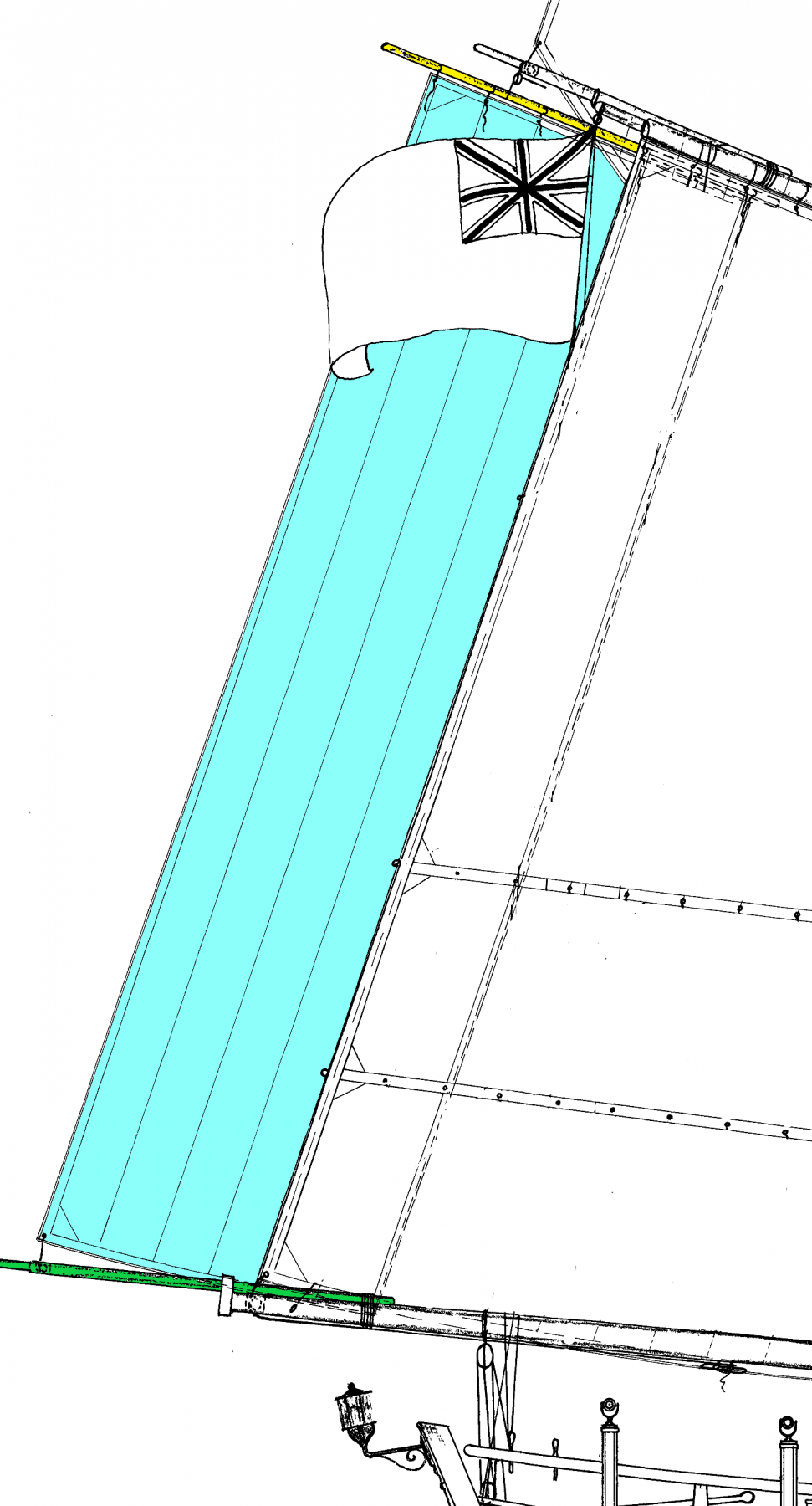
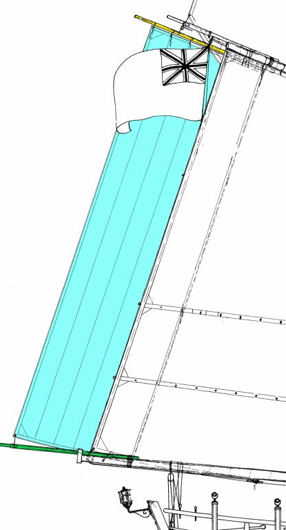
Thanks so much grsjax and as a result I have now located that in one of my texts. Carrying on from your comment - and looking back at my diagram - the upper spar (coloured yellow) supporting this ringtail sail would be called the 'ringtail boom/ or gaff/ or yard' ? Pete
-
Would really appreciate some assistance in naming the sail in the diagram partly shaded blue and partly hidden behind the main course sail on an English schooner of 1787 (Euromodel - Lyde). Pete
-
Looking all 'ship shape' Max. Even at the first planking level, the look of the ship so far exudes quality and the execution of excellent skills. Pete
-
Greetings bored in retirement!
piratepete007 replied to robert Lamba's topic in New member Introductions
Robert … send me a PM and I can assist you. Pete -
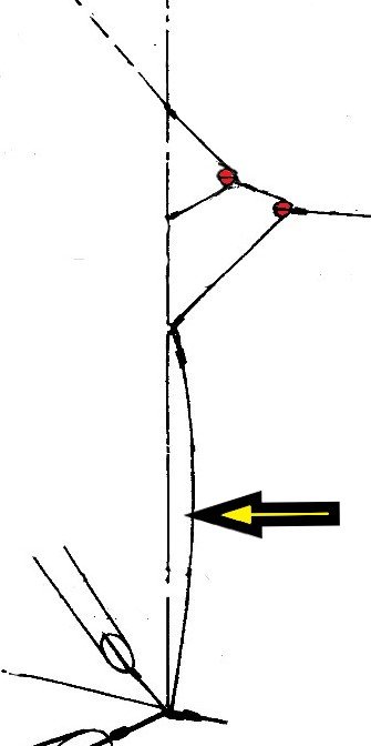
Would really appreciate some confirmation of this section of a fore course sail from a Continental ship (17C) drawing. I understand (I think) the function of the three bridles (and bowline) attached to the leech is to keep tight the windward or weather leech of the sail. However, the extra line below the bridles indicated by the large arrow is to add extra strength in keeping the course tight under tough weather conditions ???? Does this piece have a special term ? Pete