


kruginmi
-
Posts
629 -
Joined
-
Last visited
Reputation Activity
-

 kruginmi got a reaction from gieb8688 in HMS Druid by kruginmi - 1:48 - cross-section - Hahn
Another update in the evolution of the Druid-X, this time focusing on the garboard and limber strakes.
For the limber strakes I am still using the thickstuff stock (1/8"). These require a slot to allow the limber boards to fit in between this and the keelson. Using the Byrnes saw I quickly had my raw stock.
Using a spacer piece of wood to insure consistent separation from the keelson I glued in both limber strakes.
Everything ended up looking fit and proper. A good result.
As a companion it was time to put on the first regular planks on the hull (1/16"). The natural choice was the garboard strake - and in fact I did one better, the garboard strake plus one each side. These were again cut rectangular with no specific shaping. The rest of the planking will be custom fit and cut.
The ends of the planks aren't perfectly flush with the aft and fore frames. I am resisting the urge to sand them into all the outside and inside planks are attached to avoid screwing up the face of the frames - as much.
Next up is the middle stuff (my term - hah hah). Some 3/32" stuff that abuts a lot of the thickstuff prior to the regular planking. I also want to get the berth deck clamp in. It wont be too long before the lower hold is sealed in.
Mark
-
 kruginmi got a reaction from harvey1847 in HMS Druid by kruginmi - 1:48 - cross-section - Hahn
Onto the thickstuff. I have learned over and over that reading and studying only take you so far - it is the creation of an accurate 3D model that really brings things to life. And this was reinforced again here.
I had never really associated the thickstuff planks with anything other than longitudinal support. As I once again read over the available material it finally clicked: The thickstuff planks correspond with the futtock joins of the frames. This had escaped me primarily because half of these joins were never visible being on the other side of the frame. It makes perfect sense and brings additional order.
Now I understand the ramifications of how I defined the frame joins at the beginning. At first glance I would say my frames have their opposing joins too close. However, I will invoke my American made cargo ship edict which lets me bypass all normal building standards. I have learned something I did not know before.
The hull is at its widest near the forward part of this cross section and slightly reduced near the aft. I decided not to reflect this change in the thickstuff planks themselves, keeping them straight and rectangular.
The lines penciled on the internal hull represent the berth and gun deck locations. Next up is the limber and garboard strakes.
Stay Building my Friends,
mark
-
 kruginmi got a reaction from fatih79 in HMS Druid by kruginmi - 1:48 - cross-section - Hahn
Another update in the evolution of the Druid-X, this time focusing on the garboard and limber strakes.
For the limber strakes I am still using the thickstuff stock (1/8"). These require a slot to allow the limber boards to fit in between this and the keelson. Using the Byrnes saw I quickly had my raw stock.
Using a spacer piece of wood to insure consistent separation from the keelson I glued in both limber strakes.
Everything ended up looking fit and proper. A good result.
As a companion it was time to put on the first regular planks on the hull (1/16"). The natural choice was the garboard strake - and in fact I did one better, the garboard strake plus one each side. These were again cut rectangular with no specific shaping. The rest of the planking will be custom fit and cut.
The ends of the planks aren't perfectly flush with the aft and fore frames. I am resisting the urge to sand them into all the outside and inside planks are attached to avoid screwing up the face of the frames - as much.
Next up is the middle stuff (my term - hah hah). Some 3/32" stuff that abuts a lot of the thickstuff prior to the regular planking. I also want to get the berth deck clamp in. It wont be too long before the lower hold is sealed in.
Mark
-
 kruginmi got a reaction from Elmer Cornish in HMS Druid by kruginmi - 1:48 - cross-section - Hahn
Another update in the evolution of the Druid-X, this time focusing on the garboard and limber strakes.
For the limber strakes I am still using the thickstuff stock (1/8"). These require a slot to allow the limber boards to fit in between this and the keelson. Using the Byrnes saw I quickly had my raw stock.
Using a spacer piece of wood to insure consistent separation from the keelson I glued in both limber strakes.
Everything ended up looking fit and proper. A good result.
As a companion it was time to put on the first regular planks on the hull (1/16"). The natural choice was the garboard strake - and in fact I did one better, the garboard strake plus one each side. These were again cut rectangular with no specific shaping. The rest of the planking will be custom fit and cut.
The ends of the planks aren't perfectly flush with the aft and fore frames. I am resisting the urge to sand them into all the outside and inside planks are attached to avoid screwing up the face of the frames - as much.
Next up is the middle stuff (my term - hah hah). Some 3/32" stuff that abuts a lot of the thickstuff prior to the regular planking. I also want to get the berth deck clamp in. It wont be too long before the lower hold is sealed in.
Mark
-
 kruginmi got a reaction from Aussie048 in HMS Druid by kruginmi - 1:48 - cross-section - Hahn
Another update in the evolution of the Druid-X, this time focusing on the garboard and limber strakes.
For the limber strakes I am still using the thickstuff stock (1/8"). These require a slot to allow the limber boards to fit in between this and the keelson. Using the Byrnes saw I quickly had my raw stock.
Using a spacer piece of wood to insure consistent separation from the keelson I glued in both limber strakes.
Everything ended up looking fit and proper. A good result.
As a companion it was time to put on the first regular planks on the hull (1/16"). The natural choice was the garboard strake - and in fact I did one better, the garboard strake plus one each side. These were again cut rectangular with no specific shaping. The rest of the planking will be custom fit and cut.
The ends of the planks aren't perfectly flush with the aft and fore frames. I am resisting the urge to sand them into all the outside and inside planks are attached to avoid screwing up the face of the frames - as much.
Next up is the middle stuff (my term - hah hah). Some 3/32" stuff that abuts a lot of the thickstuff prior to the regular planking. I also want to get the berth deck clamp in. It wont be too long before the lower hold is sealed in.
Mark
-
 kruginmi got a reaction from kees de mol in HMS Druid by kruginmi - 1:48 - cross-section - Hahn
Another update in the evolution of the Druid-X, this time focusing on the garboard and limber strakes.
For the limber strakes I am still using the thickstuff stock (1/8"). These require a slot to allow the limber boards to fit in between this and the keelson. Using the Byrnes saw I quickly had my raw stock.
Using a spacer piece of wood to insure consistent separation from the keelson I glued in both limber strakes.
Everything ended up looking fit and proper. A good result.
As a companion it was time to put on the first regular planks on the hull (1/16"). The natural choice was the garboard strake - and in fact I did one better, the garboard strake plus one each side. These were again cut rectangular with no specific shaping. The rest of the planking will be custom fit and cut.
The ends of the planks aren't perfectly flush with the aft and fore frames. I am resisting the urge to sand them into all the outside and inside planks are attached to avoid screwing up the face of the frames - as much.
Next up is the middle stuff (my term - hah hah). Some 3/32" stuff that abuts a lot of the thickstuff prior to the regular planking. I also want to get the berth deck clamp in. It wont be too long before the lower hold is sealed in.
Mark
-
kruginmi got a reaction from fatih79 in HMS Druid by kruginmi - 1:48 - cross-section - Hahn
Onto the thickstuff. I have learned over and over that reading and studying only take you so far - it is the creation of an accurate 3D model that really brings things to life. And this was reinforced again here.
I had never really associated the thickstuff planks with anything other than longitudinal support. As I once again read over the available material it finally clicked: The thickstuff planks correspond with the futtock joins of the frames. This had escaped me primarily because half of these joins were never visible being on the other side of the frame. It makes perfect sense and brings additional order.
Now I understand the ramifications of how I defined the frame joins at the beginning. At first glance I would say my frames have their opposing joins too close. However, I will invoke my American made cargo ship edict which lets me bypass all normal building standards. I have learned something I did not know before.
The hull is at its widest near the forward part of this cross section and slightly reduced near the aft. I decided not to reflect this change in the thickstuff planks themselves, keeping them straight and rectangular.
The lines penciled on the internal hull represent the berth and gun deck locations. Next up is the limber and garboard strakes.
Stay Building my Friends,
mark
-
kruginmi got a reaction from Aussie048 in HMS Druid by kruginmi - 1:48 - cross-section - Hahn
Onto the thickstuff. I have learned over and over that reading and studying only take you so far - it is the creation of an accurate 3D model that really brings things to life. And this was reinforced again here.
I had never really associated the thickstuff planks with anything other than longitudinal support. As I once again read over the available material it finally clicked: The thickstuff planks correspond with the futtock joins of the frames. This had escaped me primarily because half of these joins were never visible being on the other side of the frame. It makes perfect sense and brings additional order.
Now I understand the ramifications of how I defined the frame joins at the beginning. At first glance I would say my frames have their opposing joins too close. However, I will invoke my American made cargo ship edict which lets me bypass all normal building standards. I have learned something I did not know before.
The hull is at its widest near the forward part of this cross section and slightly reduced near the aft. I decided not to reflect this change in the thickstuff planks themselves, keeping them straight and rectangular.
The lines penciled on the internal hull represent the berth and gun deck locations. Next up is the limber and garboard strakes.
Stay Building my Friends,
mark
-
 kruginmi got a reaction from dvm27 in HMS Druid by kruginmi - 1:48 - cross-section - Hahn
Onto the thickstuff. I have learned over and over that reading and studying only take you so far - it is the creation of an accurate 3D model that really brings things to life. And this was reinforced again here.
I had never really associated the thickstuff planks with anything other than longitudinal support. As I once again read over the available material it finally clicked: The thickstuff planks correspond with the futtock joins of the frames. This had escaped me primarily because half of these joins were never visible being on the other side of the frame. It makes perfect sense and brings additional order.
Now I understand the ramifications of how I defined the frame joins at the beginning. At first glance I would say my frames have their opposing joins too close. However, I will invoke my American made cargo ship edict which lets me bypass all normal building standards. I have learned something I did not know before.
The hull is at its widest near the forward part of this cross section and slightly reduced near the aft. I decided not to reflect this change in the thickstuff planks themselves, keeping them straight and rectangular.
The lines penciled on the internal hull represent the berth and gun deck locations. Next up is the limber and garboard strakes.
Stay Building my Friends,
mark
-
 kruginmi got a reaction from qwerty2008 in HMS Druid by kruginmi - 1:48 - cross-section - Hahn
Onto the thickstuff. I have learned over and over that reading and studying only take you so far - it is the creation of an accurate 3D model that really brings things to life. And this was reinforced again here.
I had never really associated the thickstuff planks with anything other than longitudinal support. As I once again read over the available material it finally clicked: The thickstuff planks correspond with the futtock joins of the frames. This had escaped me primarily because half of these joins were never visible being on the other side of the frame. It makes perfect sense and brings additional order.
Now I understand the ramifications of how I defined the frame joins at the beginning. At first glance I would say my frames have their opposing joins too close. However, I will invoke my American made cargo ship edict which lets me bypass all normal building standards. I have learned something I did not know before.
The hull is at its widest near the forward part of this cross section and slightly reduced near the aft. I decided not to reflect this change in the thickstuff planks themselves, keeping them straight and rectangular.
The lines penciled on the internal hull represent the berth and gun deck locations. Next up is the limber and garboard strakes.
Stay Building my Friends,
mark
-
 kruginmi got a reaction from Mike Y in HMS Druid by kruginmi - 1:48 - cross-section - Hahn
Onto the thickstuff. I have learned over and over that reading and studying only take you so far - it is the creation of an accurate 3D model that really brings things to life. And this was reinforced again here.
I had never really associated the thickstuff planks with anything other than longitudinal support. As I once again read over the available material it finally clicked: The thickstuff planks correspond with the futtock joins of the frames. This had escaped me primarily because half of these joins were never visible being on the other side of the frame. It makes perfect sense and brings additional order.
Now I understand the ramifications of how I defined the frame joins at the beginning. At first glance I would say my frames have their opposing joins too close. However, I will invoke my American made cargo ship edict which lets me bypass all normal building standards. I have learned something I did not know before.
The hull is at its widest near the forward part of this cross section and slightly reduced near the aft. I decided not to reflect this change in the thickstuff planks themselves, keeping them straight and rectangular.
The lines penciled on the internal hull represent the berth and gun deck locations. Next up is the limber and garboard strakes.
Stay Building my Friends,
mark
-
 kruginmi got a reaction from tadheus in HMS Druid by kruginmi - 1:48 - cross-section - Hahn
Onto the thickstuff. I have learned over and over that reading and studying only take you so far - it is the creation of an accurate 3D model that really brings things to life. And this was reinforced again here.
I had never really associated the thickstuff planks with anything other than longitudinal support. As I once again read over the available material it finally clicked: The thickstuff planks correspond with the futtock joins of the frames. This had escaped me primarily because half of these joins were never visible being on the other side of the frame. It makes perfect sense and brings additional order.
Now I understand the ramifications of how I defined the frame joins at the beginning. At first glance I would say my frames have their opposing joins too close. However, I will invoke my American made cargo ship edict which lets me bypass all normal building standards. I have learned something I did not know before.
The hull is at its widest near the forward part of this cross section and slightly reduced near the aft. I decided not to reflect this change in the thickstuff planks themselves, keeping them straight and rectangular.
The lines penciled on the internal hull represent the berth and gun deck locations. Next up is the limber and garboard strakes.
Stay Building my Friends,
mark
-
 kruginmi got a reaction from mtaylor in HMS Druid by kruginmi - 1:48 - cross-section - Hahn
Onto the thickstuff. I have learned over and over that reading and studying only take you so far - it is the creation of an accurate 3D model that really brings things to life. And this was reinforced again here.
I had never really associated the thickstuff planks with anything other than longitudinal support. As I once again read over the available material it finally clicked: The thickstuff planks correspond with the futtock joins of the frames. This had escaped me primarily because half of these joins were never visible being on the other side of the frame. It makes perfect sense and brings additional order.
Now I understand the ramifications of how I defined the frame joins at the beginning. At first glance I would say my frames have their opposing joins too close. However, I will invoke my American made cargo ship edict which lets me bypass all normal building standards. I have learned something I did not know before.
The hull is at its widest near the forward part of this cross section and slightly reduced near the aft. I decided not to reflect this change in the thickstuff planks themselves, keeping them straight and rectangular.
The lines penciled on the internal hull represent the berth and gun deck locations. Next up is the limber and garboard strakes.
Stay Building my Friends,
mark
-
kruginmi got a reaction from harvey1847 in HMS Druid by kruginmi - 1:48 - cross-section - Hahn
The task for the day was a Keel Rabbet. The difference for me is that this rabbet is more than for looks. I actually need a garboard strake to fit into the rabbet and given the cross section you get to view the results on two ends.
So....off I went. I did drill through the keel, the frames and partway through the keelson at each frame. Four of these holes where then drilled through the false keel. Adding trunnels through the whole assembly made it very stiff.
I am pretty happy with the results. Now I get to start working on stuff that will for the most part be seen!
mark
-
kruginmi got a reaction from harvey1847 in HMS Druid by kruginmi - 1:48 - cross-section - Hahn
It has been some banner time in the workshop the last couple of days. I was boresighted on getting past the frames so this afternoon I was back at it, this time for the internal fairing. To borrow a phrase "Say hello to my little friends"
Cabinet scrapers are very effective in removing wood on the internal hull. Supplement that with some final sanding and you can do a lot without a lot of sawdust flying about. More evidence of my activity is the current state of my rough worktable:
Definitely needs some cleanup tomorrow, but a tidy workshop does not show progress! At the end of the day I can stand back and look at my hull with keel and keelson on (but not yet attached). Still need another hour or so of refinement but I am happy with the progress and I can see the finish for this part of the project:
Tomorrow probably switch to the Lady Anne for awhile.
Stay Building My Friends,
Mark
-
kruginmi got a reaction from gieb8688 in HMS Druid by kruginmi - 1:48 - cross-section - Hahn
Thanks everyone for stopping by.
Tonight was another big night for Druid-X: I affixed the first plank. I am putting the wales on at this time to provide greater longitudinal strength. I traced the wale pattern off of the plans and defined three plank widths. The curvature of the wales was transferred to a piece of 1/8" thick basswood (double the 1/16" plank width) and this pattern cut / sanded out. After I was satisfied with the curve I used dividers to define the width of one plank and also cut and sanded this out. This continued for all three planks.
The middle plank was to span entirely across the cross section, the upper and lower ones being jointed three frames in (different sides). I affixed the middle plank first given it was the easiest one. The following pic shows the top one being put on:
I now laugh looking at this. It was with the click of the shutter that I made a mental note to insure the joint in the lower was made on the opposite side. The opposite side of.the.joint.that.I.had.forgot.to.put.in. The glue sets fast but I was able to pry off the top plank without too much damage, cut the joint and re-attach. Here is a shot of what it was supposed to look like originally:
I added the third plank then sanded the edges flush with the frames.
In this pic you can see the face on view and also the chocks completed on the opposite side of the cross section.
Trying to accomplish a little bit with every hour - Stay Building my Friends,
Mark
-
 kruginmi got a reaction from CharlieZardoz in HMS Druid by kruginmi - 1:48 - cross-section - Hahn
Slow but steady. I worked the inlays into the front frame using walnut - that should make them pop with the finish. After everything looked good I glued the frame to the jig. I have begun work with the 27th frame (opposite) to do the same. I waited until this time for these pieces so I could accurately account for the bevels. This is targeted for eye candy so I wanted the join pieces to be placed consistently to look their best.
Lots of time spent on the frames. If you have a solid base that is correct, the rest of the build is sooooo much easier. Bummer most of this will not be seen/
The outside of the hull is now faired (the inside is not as is pretty clear). After doing the 27th frame my goal will be to get the wales on for maximum strength and then work the rabbet into the keel prior to attaching that.
Stay Building my Friends,
Mark
-
kruginmi got a reaction from gieb8688 in HMS Druid by kruginmi - 1:48 - cross-section - Hahn
Now to put the bevels in.
First step is to add spacers between the frames where the main wales will be. So....I need to know the height for each frame. I used a light box to copy the plans for the cross section to a blank piece of paper. I then cut the plans so the floor was equivalent to the base jig. This was then glued to a form that allows measurements to be taken off.
.
I then was able to take measurements of the wale upper and lower limits and transfer to the model. Then spacer pieces were added. THEN the sanding starts. I was just focusing on one of the external sides initially. When the full outside is done I will attach the wales for complete stiffness before attempting the inside.
I did find the frames had some 'issues' conforming to a pre-bevel ready install. I had flashbacks to the original Druid when I had problems in the same area. I had though using the top spreaders would solve how this happened but I think there are a couple of issues with the drawn frames on the plans. I actually cut one of the lower legs and re-glued in a slightly different orientation to make things match up better. Some other frames had their slots enlarged to allow more movement prior to gluing. You go slow and check your progress often and it was slowly brought into alignment.
I had a plank at the ready and checked how it laid on the hull often. As a note the first and last frame are still not glued in. I wanted to see exactly how the bevels affected them prior to adding the futtuck join pieces to insure they visually looked right.
For a current look and comparison, the following shot shows a beveled hull on the right and untouched on the left - big difference.
All this work will be hidden (except the keel) and it might thought to be overkill but I wanted this build to be equivalent to the original build.
As an aside, I include a current view of my full HMS Druid at the Lowell Arts Building (pic from them). Not looking too shabby.
Stay Building my Friends,
Mark
-
kruginmi got a reaction from gieb8688 in HMS Druid by kruginmi - 1:48 - cross-section - Hahn
Thanks for all the likes.
Big day in the Krug household - time to glue the frames to the jig. I did not glue the outermost frames, saving those for further refinements off board. The keel is still removable.
I glued the outermost remaining ones to provide a firm grounding on opposite ends to keep everything in line (the keel riser notwithstanding). I then worked inward gluing one at a time. The frame was pushed below it's required level, the keel re-attached to the existing frames, then the new frame pulled up into position in its slot. Wait a few minutes and on to the next one.
As can be seen, the keel was cut to the correct depth and the false keel also cut. No longer any need for the keel risers.
Next is to add some frame spacers at the wale location to really lock everything in before sanding, and detail the outer frames.
Interesting to note with this building style the keel rabbet is not finished at this time. In fact I used the frames as installed to determine exactly where the rabbet should be.
Mark
-
 kruginmi got a reaction from Erebus and Terror in HMS Druid by kruginmi - 1:48 - cross-section - Hahn
Just continuing to motor right along.
The sled on my Byrnes saw almost made this too easy (take'em when you can get'em). I rubber cemented the required keel slot locations onto a piece of basswood (will cut to correct depth later on).
After it was dry I adjusted my Byrnes saw to the correct depth and using the sled cut all slots perfectly out in less than 5 minutes (test fitting a frame for each slot as I went).
I also cut a slot on the keel height holders - which was a mistake, but no harm done. The keel holder was the proper height of the keel BEFORE cutting. With out the slots, the frames had actually been adjusted a tad too low in the previous pics taken. Amazing how things like this pop up! Glad I caught it now.
Then everything was put together with the frames into the slots (the picture has the incorrect slot in the keel holders). Amazing how rigid and strong the structure became.
I now need to fix that keel holder and I will be good for starting to drill some trunnel holes as well as cut my purpleheart false keel.
Stay Building My Friends,
Mark
-
kruginmi got a reaction from Erebus and Terror in HMS Druid by kruginmi - 1:48 - cross-section - Hahn
With some free time on this New Year's Day (everyone sleeping in) I dashed down to the shipyard. Things seemed to go pretty fast at this stage.
I removed all paper from the frames and added the missing support wood. I then methodically worked the positioning of the ten frames onto the jig. Lots of back and forth to the scroll saw but well worth it.
Still some cleanup to do on each frame, primarily around the keel slot before I glue them into the base slots. Then it will be on to the real keel.
I know the hull is centered on the jig and correctly positioned. Any measurement on either side will match. The base is parallel to the keel. This should limit the 'surprises' in the future.
Stay Building my Friends,
Mark
-
kruginmi got a reaction from Erebus and Terror in HMS Druid by kruginmi - 1:48 - cross-section - Hahn
With the frames roughed out it was time to think about how to make the Hahn style jig. I had success previously with the full hull but had lessons learned for my building style (read accuracy and capability). So I came up with the following:
First off, I did copy the base pattern off of the plans but did not go and cut it all out at once. Lots of small errors compound to very noticeable ones. So after cutting out the center portion I picked the first frame, centered it over its location then cut out notches for it to fit snugly. I also fit out pillars that insured the keel was at the exact height and centered over the jig. So the frame is inserted into its groove, the pseudo keel is put into position and then the frame is pulled up into position perpendicular to the board.
For the next frame I inserted a 1/8" board spacer to define the start point of the frame, then measured as above off of this starting position. Very close to the plans but tweeked here and there. So everything is based off of the first frame.
Nothing is glued yet (still have to scrape off the remaining templates). After everything is verified, the frames will be glued and then the real keel will be fashioned.
Also need to detail out the face frames of the first and last exposed frames.
Stay Building My Friends,
Mark
-
kruginmi got a reaction from Erebus and Terror in HMS Druid by kruginmi - 1:48 - cross-section - Hahn
With the holidays (and the family flu) in the rear view mirror I finally spent some time in the shipyard. I finally got all ten frames rough cut out. No bevels yet (after they are installed in the jig) and the face frame sides will have futtock join pieces with trunnels added.
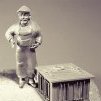
You can see one of my Christmas gifts from the kids - 1:48 scale plastic figures. They are Air Force ground crew figures, so some modifications will need to be made, however I really liked the look of them on the full Druid. Nice to see the figures fit so well. They will be all over the cross section: climbing, cleaning, firing - you name it.
Next up is to cut out the base jig to hold these frames inverted (the Hahn method). Hope to pick up the wood tomorrow. You can also see the other big gift from the family: Volume IV of the Swan books - AWESOME!
BTW: I picked up this sanding belt cleaner bar and it works fantastic. I would highly recommend. It basically brings the sandpaper back to like new. The top of the spindle sander hasn't been treated, below it has. Simply push it against the running drum whenever it is starting to gum up.
In other news: The full Druid has been invited to another Art Showing for January in Lowell, Michigan. This will be followed by a request for a business to host for another month. Tremendous positive feedback.
Stay Building My Friends,
Mark
-
kruginmi got a reaction from Erebus and Terror in HMS Druid by kruginmi - 1:48 - cross-section - Hahn
In the Army there is a saying that no plan survives first contact, and it looks like it applies to ship modeling also. After butchering a frame and a half I took a step back and reevaluated how I was making the frames. After punching out three successful frames I have found what works for me.
I still used the rough cut out futtock pieces (trying to get a 1/16" buffer around). I then proceeded to exact cut the join edges without refining the other edges.
The layers were then independently glued together over an uncut picture of the frame. I omitted the upper pieces on the top layer to allow both layers to be aligned.
Then using a faux keel for center alignment and matching the upper parts of the frames the frames were glued together.
For the final steps after drying I used the spindle sander to finalize the frame outline and removed the last of the paper templates.
This is what worked for me. Now just to get the rest of these frames finished off (if I can keep the rest of the family from getting the flu).
Stay Building My Friends,
Mark
-
 kruginmi got a reaction from captainbob in HMS Druid by kruginmi - 1:48 - cross-section - Hahn
Onto the thickstuff. I have learned over and over that reading and studying only take you so far - it is the creation of an accurate 3D model that really brings things to life. And this was reinforced again here.
I had never really associated the thickstuff planks with anything other than longitudinal support. As I once again read over the available material it finally clicked: The thickstuff planks correspond with the futtock joins of the frames. This had escaped me primarily because half of these joins were never visible being on the other side of the frame. It makes perfect sense and brings additional order.
Now I understand the ramifications of how I defined the frame joins at the beginning. At first glance I would say my frames have their opposing joins too close. However, I will invoke my American made cargo ship edict which lets me bypass all normal building standards. I have learned something I did not know before.
The hull is at its widest near the forward part of this cross section and slightly reduced near the aft. I decided not to reflect this change in the thickstuff planks themselves, keeping them straight and rectangular.
The lines penciled on the internal hull represent the berth and gun deck locations. Next up is the limber and garboard strakes.
Stay Building my Friends,
mark