Charter33
-
Posts
455 -
Joined
-
Last visited
Content Type
Profiles
Forums
Gallery
Events
Everything posted by Charter33
-
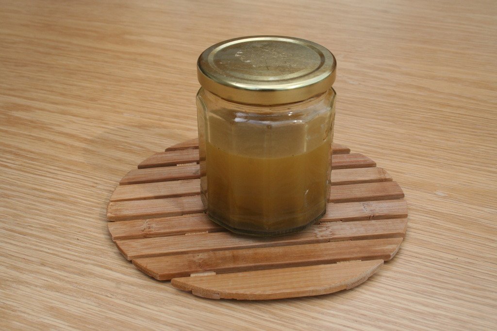
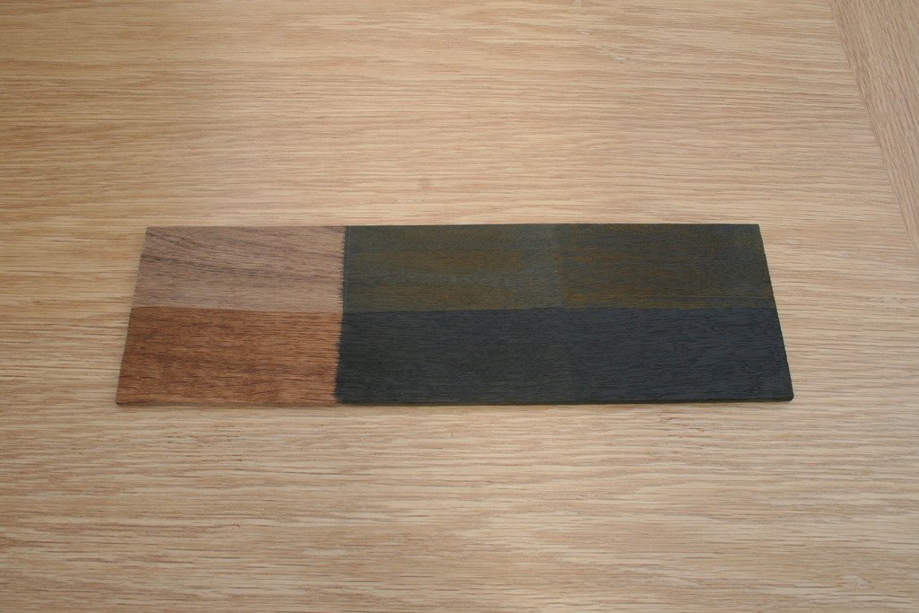
Some photographic detail …….. Driving past the old work place the other day I decided to drop in to catch up with colleagues and pick up a few more of my own bits and pieces – tools etc. Sitting at the back of a shelf in a workshop cupboard was a jar of the vinegar/ rusty iron ‘brew’ so I thought I’d produce a test piece to show the effect of the ebonising stain on wood. The vinegar and rusty iron mix ready for use. The oak sample was divided into three, the first left natural, the third area was pre-soaked with cold tea to increase the tannin content, and once this had dried the second and third areas were both coated with the ebonising fluid. Initially nothing seems to be happening but over the next hour or so the effect became more pronounced. Once the wood had dried half the sample was coated with matt varnish which further enhances the effect. As oak is not often an ideal wood for modelling purposes, this is what happened when the fluid was applied to a walnut off-cut from my Caldercraft Victory. As walnut has a lower tannin content than oak pre-soaking in tea is beneficial. I hope this is of some interest, any task that begins with brewing tea has a lot going for it, almost as good as a cold beer once a task is completed! Cheers, Graham.
-
Hi David, I'm no ICT expert but ...... I'm sure it's possible - try moving the 'flashing' cursor to the bottom right hand corner of a picture and then tap the 'return' key a couple of times to add a few line spaces. You should then be able to type in your comments there. Hope I'm not guilty of teaching you to 'suck eggs' (!) but I tend to write my text first as a word document leaving gaps for the pictures , cut and paste this into the 'reply' box and then upload the pictures into these spaces. I still struggle with the frustrations these clever tech tools throw up at me at times - and I take my hat off to those clever devils who manage to annotate their pictures with arrows, coloured text etc. Hope this helps. Cheers, Graham
-
Hi, I've been using this on the bowls and platters that I turn on a lathe for many years. Wire wool is not essential, any rusty iron will do. I personally use white vinegar. Like Captainbob explained, wiping the surface of the wood with tea (soggy teabags work too!) will make the end result darker as does applying several coats of the iron/ vinegar mix. I find this process most effective when used on oak because of it's natural tannin content. I believe that the 'ebonising' effect is due to the chemical reaction between the tannin and the acid in the vinegar. Once dry any wood finish can be applied. I like this technique because of the penetration that can be achieved compared with paints etc. that just sit on the surface. Cheers, Graham.
-
Impressive work! - especially your method of applying second planking, the sharpness of the paint finish and the quality of the copper plating. You're a couple of pages of the instruction manual ahead of me. I shall be following your progress with considerable interest. Cheers, Graham.
-
Hi, Some advice needed, please. I'm close to completing the lining of the port side gun ports but am thinking about how to deal with the upper gun ports 'with lids'. At the moment the linings that have been completed are set back the required 1 mm on the outside but are slightly proud inside and await their final trimming. Are these linings finished flush with the inside planking or should they also be slightly recessed? Secondly, and irrespective of the answer to the first question, should the edges of these linings on the inner side be finished with red ocher or yellow? Looking at the instructions, images online and exploring other Victory build logs has proved inconclusive. ....... A quick update on the Triton project (Complete) I alluded to a couple of posts ago - the local printers charge very reasonable rates and the resulting plan printed 'true' to scale, I've located a source of cherry timber just over 40 minutes away and I hope to make the trip in a couple of days if I can escape from decorating the bathroom! Just one fly in the ointment - seems the project is temporarily closed to new members .... or maybe this only applies to the cross section? In the mean time there's still plenty to be getting on with. Cheers, Graham.
-
You take model ship building to a whole new level Ed. I am totally in awe of the skills and detail your work shows - quite simply inspirational. Thank you. Graham
- 3,618 replies
-
- 4
-

-
- young america
- clipper
- (and 1 more)
-
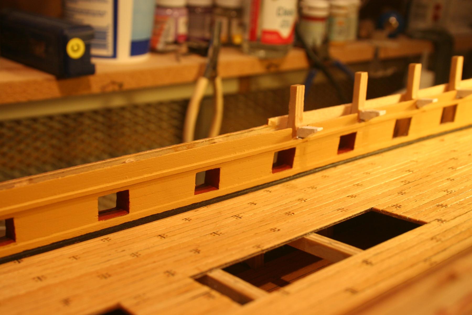
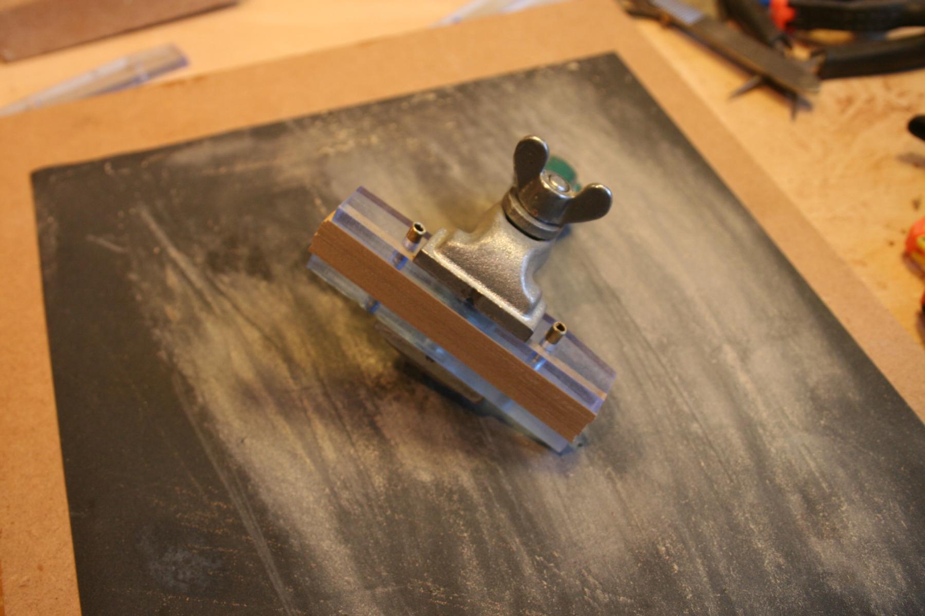
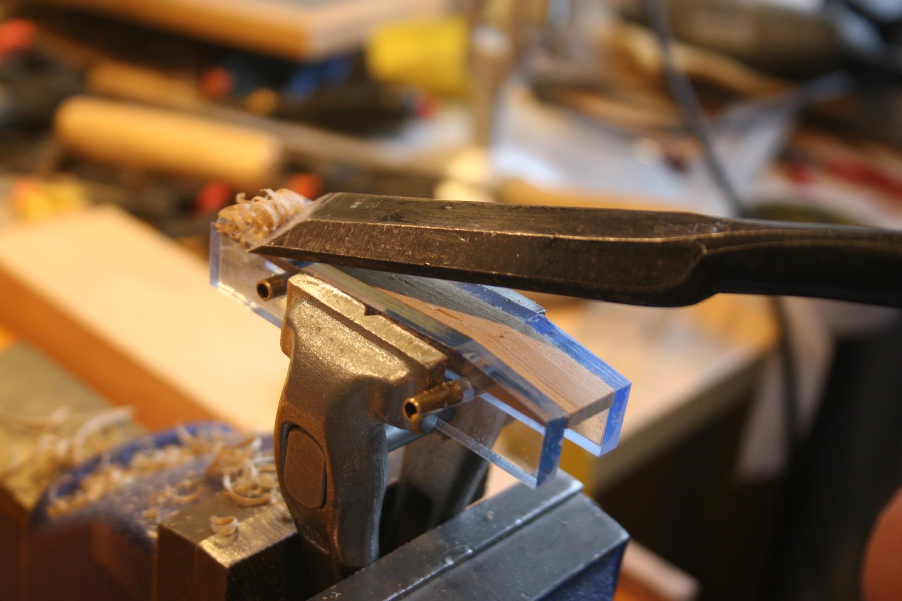
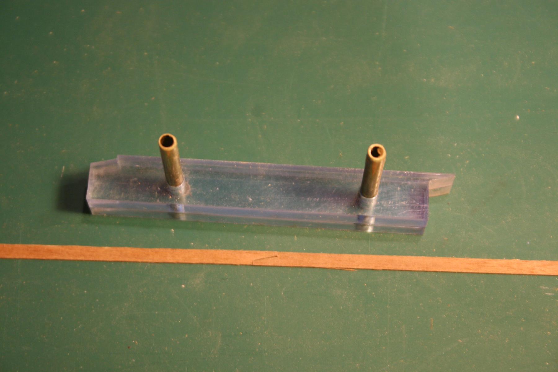
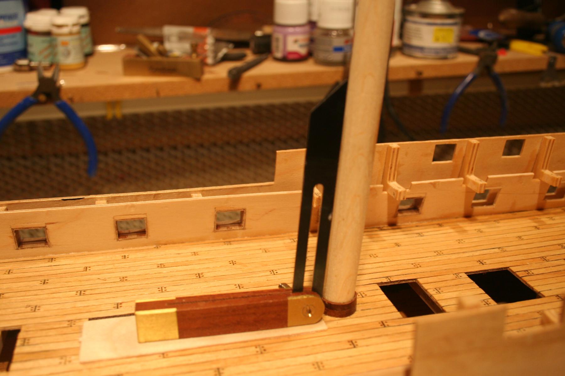
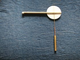
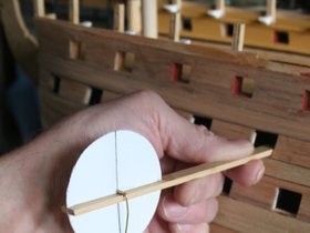
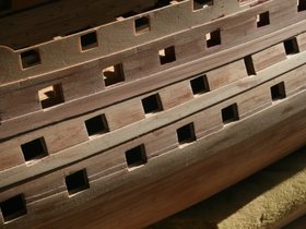
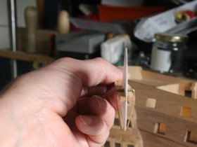
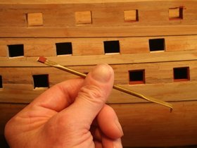
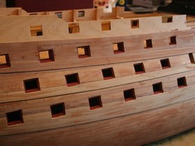
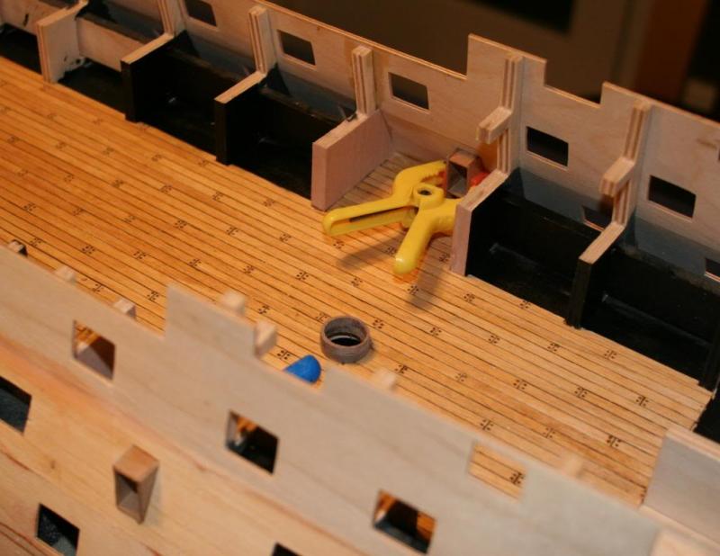
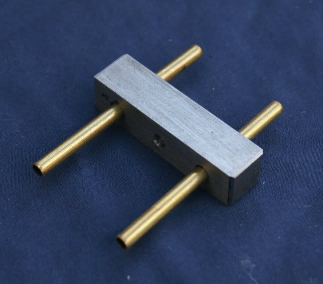
Hi, The lining of the gun ports was one task where it really paid to do some homework and invest time reviewing the excellent build logs available through this site. I would never have thought of adding balsa strips behind the edges of the ports to increase the gluing area. I went for 2 x 2 mm strips and produced this simple aid to help get them in position. It’s based on Gil’s example (thank you!) but rather than using a spirit level to ensure that horizontal pieces were correctly positioned I added a simple ‘clinometer’. With the hull leveled, when the plumb line matched the vertical line on the plastic disc the strips were correctly aligned. This device was flipped 180 degrees to deal with the strips at the top of each port. Made from whatever I could find in the workshop it’s a bit ‘Heath Robinson’ but it does the job. The lower and middle rows of gun ports were now straight forward to line with pre-painted strips. The gap between the ‘holding pins’ and the wooden strip was just right to enable this tool to be used grip and tweek the angle of the horizontal strips of walnut to their final position. A second simple and very effective tool I made was this one: Its purpose is to help manouvre the cut strips onto place and ensure that the front edge of the lining is set back the required 1 mm. Basically a 5” length of 4 mm dia. brass tube, flattened both ends. For the depth gauge a scrap of wood was glued the appropriate distance back from the end, and the 90 degree return at the other end was useful for pulling strips that were too far in back into place. Balsa strips in place. The ports on the upper gun deck were the most challenging. For the side pieces I resorted to making individual templates to the correct size and then using these to mark out the required shape onto the wood. Starboard side is now complete ….. ........ but I think a bit of tidying up of the workbench would be a good idea before tackling the other side!…. Cheers for now, Graham.
-
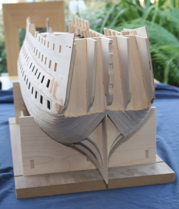
Hi, Tackling the wales proved to be fairly straight forward. After taking measurements from the plan and transferring them onto the hull, a strip of wood was pinned on these marks and, after a little ‘fine adjustment’, the curved lines were marked on. The majority of the prepared pieces fitted straight on and CA glue was used for bonding. At the bow and stern some additional shaping was required together with gentle bending with plank ‘nippers’. These photographs show the work in progress and the final results. Drifting randomly through the wide ranging posts on this site the other evening I came across many superb examples of the model makers art that reminded me of a time, back in the mid-1960s, when the ‘Birthday treat’ of choice was a trip across London to visit the Cutty Sark followed by the model ship galleries at the National Maritime Museum, Greenwich. It was these amazing models, mostly ‘plank on frame’, that sparked a lifetime’s interest. Sadly these wonderfully detailed models are no longer on display although they can be examined to some extent on-line. Why am I rambling on about this? Well – one of the sections I was exploring that started this reminiscing was the HMS Triton project. WOW! My head is telling me to keep focused, the ‘Victory’ journey has a long way still to go, my heart is saying – what a challenge! The build logs, both completed models and works in progress, are very impressive. It costs nothing to start planning… the keel plans are easily down loaded,…. and there just happens to be a very helpful and friendly print shop less than a mile away ……mmmm Meanwhile, it time to start lining the gun ports.


-
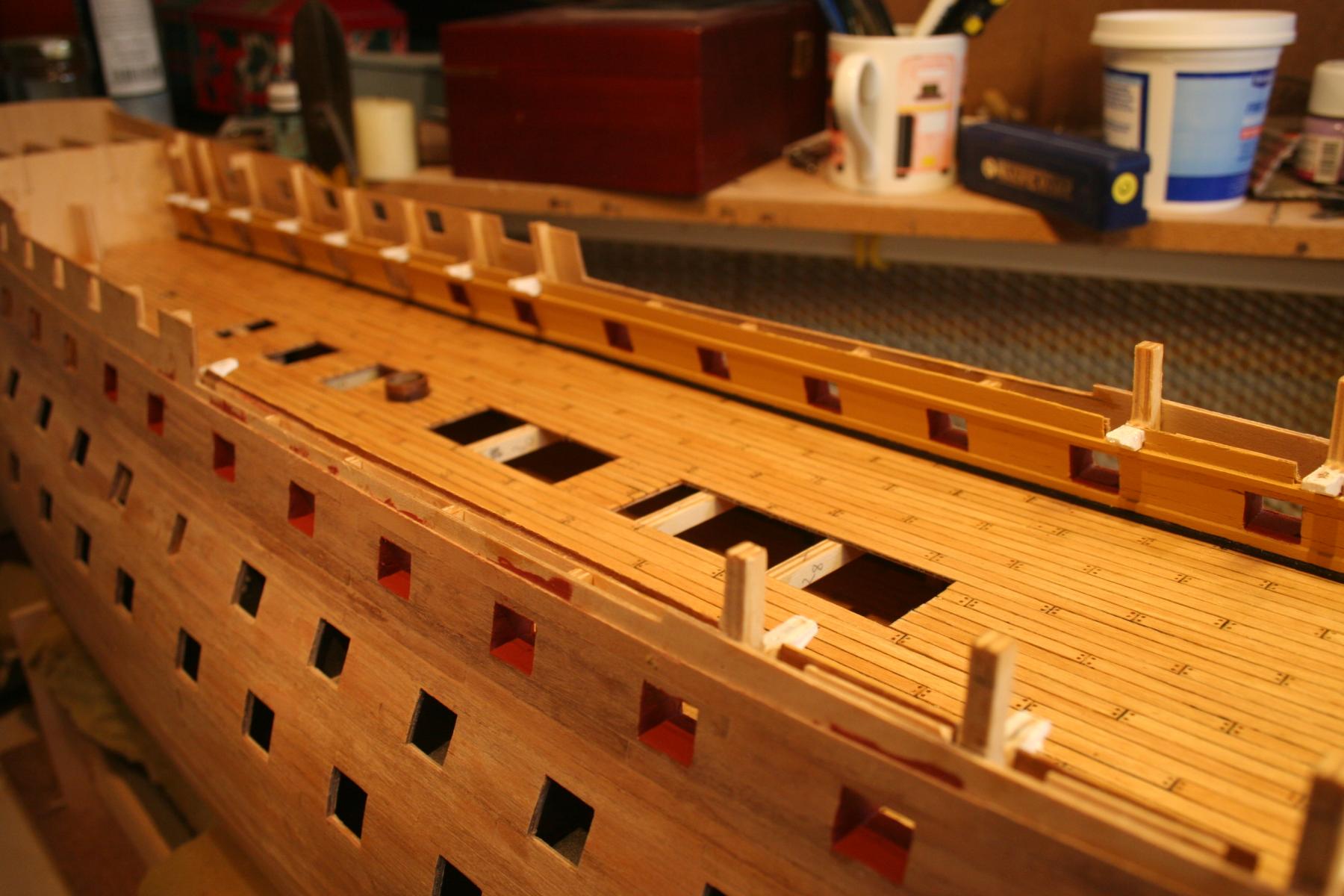
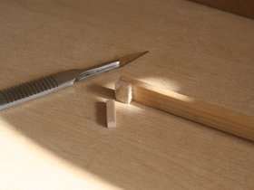
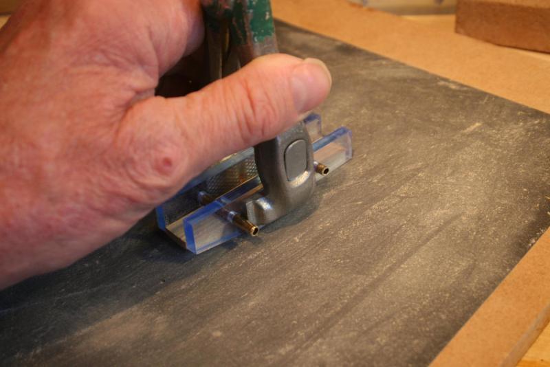
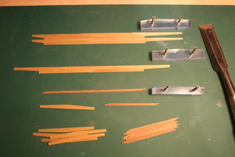
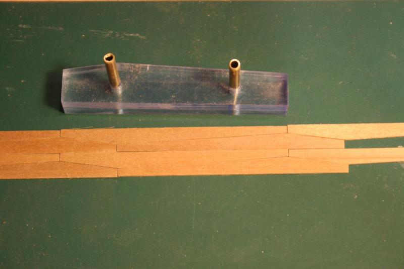
Hi Folks, I’ve finally finished planking the inner bulwarks and added the additional details I alluded to in my last post. The waterways were made from 2 x 2 mm stock walnut strip with the top corner sanded to a radius, on top of that a strip of 3 x 1mm was used for the stringer , and the beam shelf was made from 2 x 2mm stock sanded down to 2 x 1mm. All three strips were pre-painted prior to fitting and the whole lot given a second coat of yellow ochre once the glue had dried. I also did a little shaping of the deck supports with a ½” drum sander in Dremel drill before painting them white. The next challenge, and one I’ve been looking forward to, is tackling the wales. The first job was to see if the jigs I made to shape the various plank profiles would work. One length of walnut strip cuts into eleven blanks. These were stacked together and sandwiched between the sides of the jig and clamped with a hand vice. The first step was to sand one edge flat and smooth. The blanks were the flipped over and sanded to length. The hand vice was then mounted in a bench vice and a chisel was used to shave the blanks down to the final profile with a final sanding to complete the process. The three profiles, anchor stock, top and butt and simple scarf fit together well on a flat surface. I just hope they will do the same when fitted to the curved surface of the hull – time will tell!


-
Thank you for your kind and encouraging comments, Michael and Pat. Just been reading and enjoying your 'Wasa' build log, Michael - no way is a Victory Model beyond your skill set! Superb work and detail. I'll be a regular follower of your build log now that I have found it. Cheers, Graham.
-
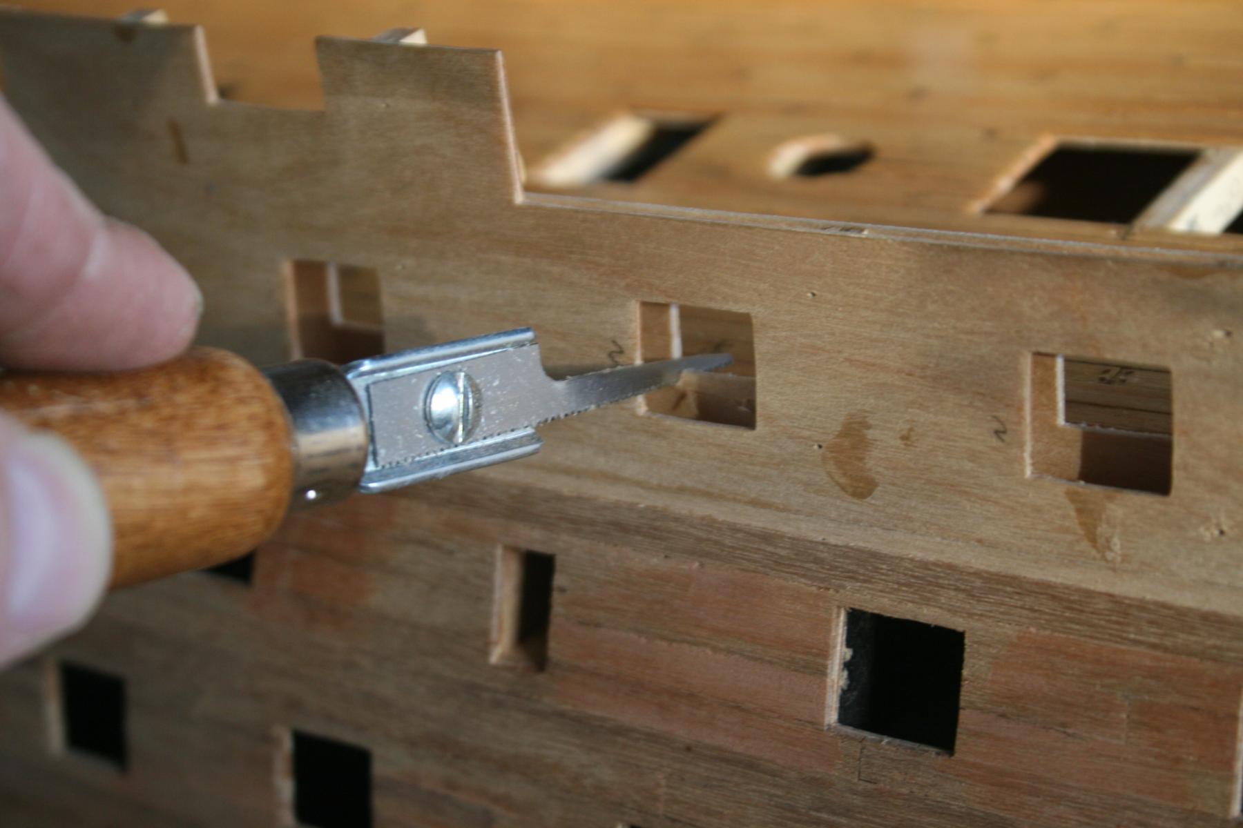
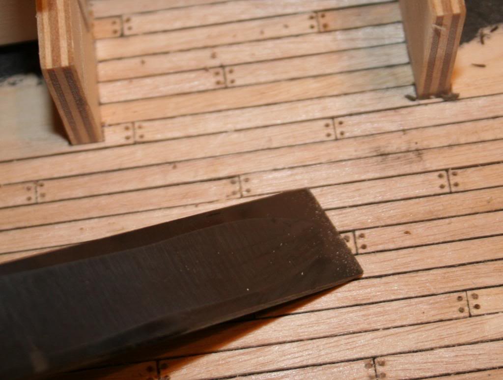
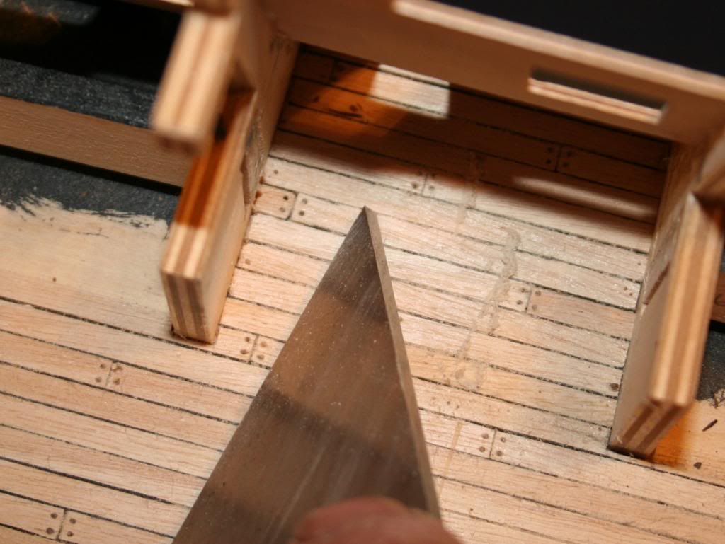
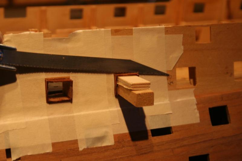
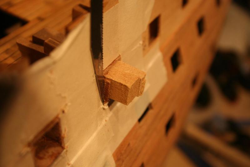
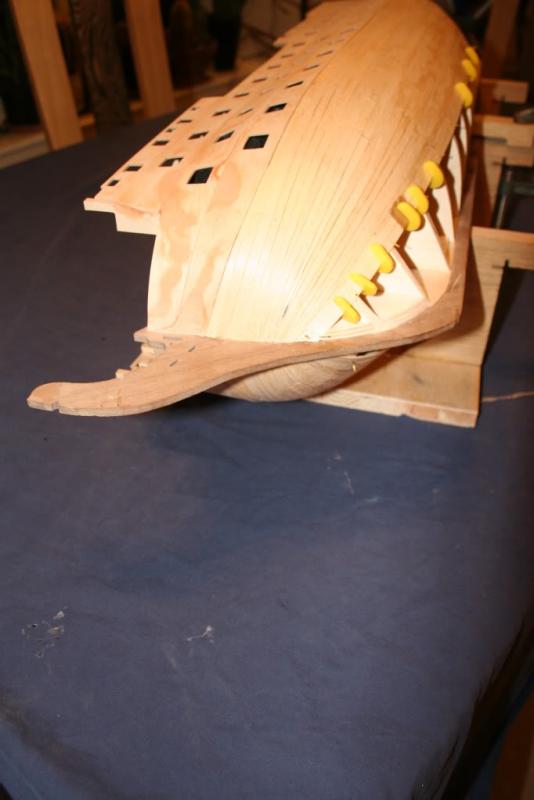
Hi, A quick up-date. Having completed the planking and varnishing of the upper gun deck the mast coats have been made, shaped and added to deck. Sounds easy but those rings are so fragile and great care was needed, especially when adjusting the internal hole on the main mast coat to allow for the angle. Lining the ‘gun ports without lids’ was fairly straight forward. To cut the lining back level with the hull I used the saber saw, the Kugihiki flush saw I used for the entry ports being; a bit too big to get into some of the more awkward internal areas, and it’s currently locked up in a secure cabinet at school awaiting my return to work, hopefully in a couple of months’ time. The saber saw blade needed to have the kerf removed from either side to prevent damaging the areas surrounding the cut, and this was quickly achieved with an oil stone. Supporting the back edge of each lining element was essential to prevent splitting or tearing the wood. I achieved this with a length of ply inserted and wedged inside the gun port for the top piece, and double wedges inserted to tackle the sides. I’m a bit of a hoarder fortunately. These MDF wedges were originally used to build ‘washout’ into the wings of an electric powered glider and came close to being binned! Masking tape around the external side of the gun ports had two purposes – firstly to further protect the surfaces from damage from the saw, and secondly to ensure the edges were sawn just proud of the hull allowing these edges to be finished flush with glass paper. After a light sanding of the inside surfaces a coat of red ocher has been applied and the next task is to plank the inside bulwark patterns. Here I hope to attempt to emulate the additional details of beam shelves, stringers and waterways as shown on ‘Maestro’ Gil Middleton’s superb build log. I’ll need to stock up on some additional walnut strip but an excuse to get out of the house and drive over to the model shop in Windsor is always welcome! Cheers, Graham.
-
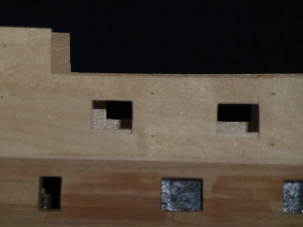
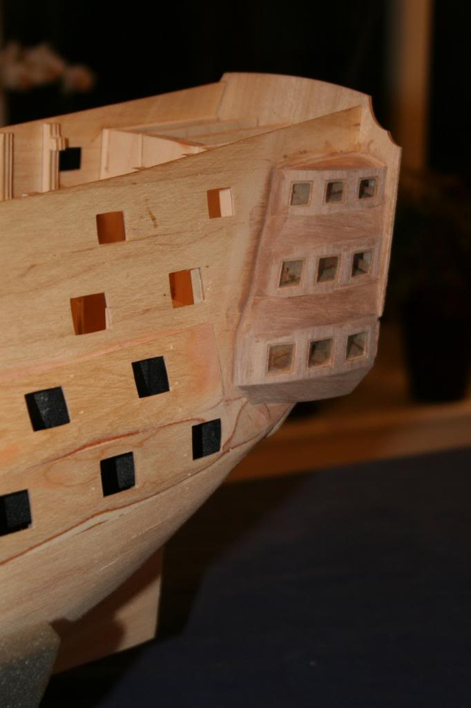
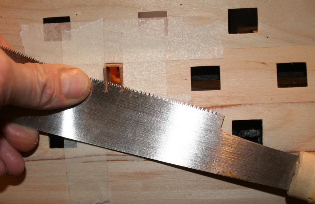
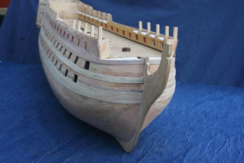
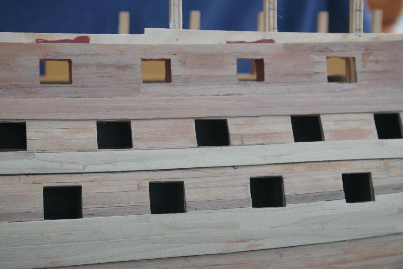
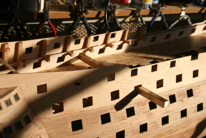
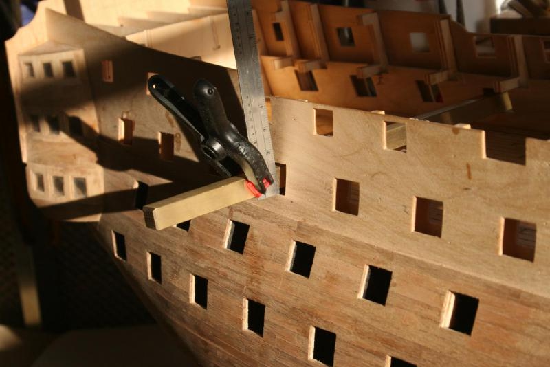
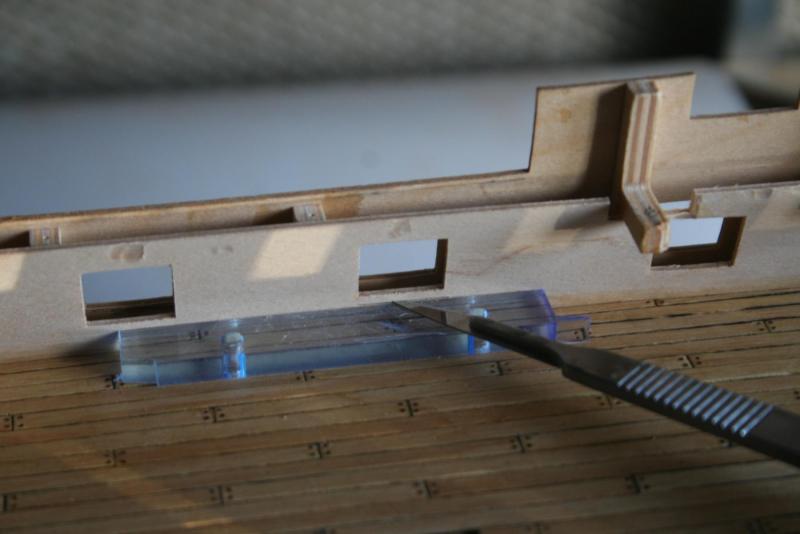
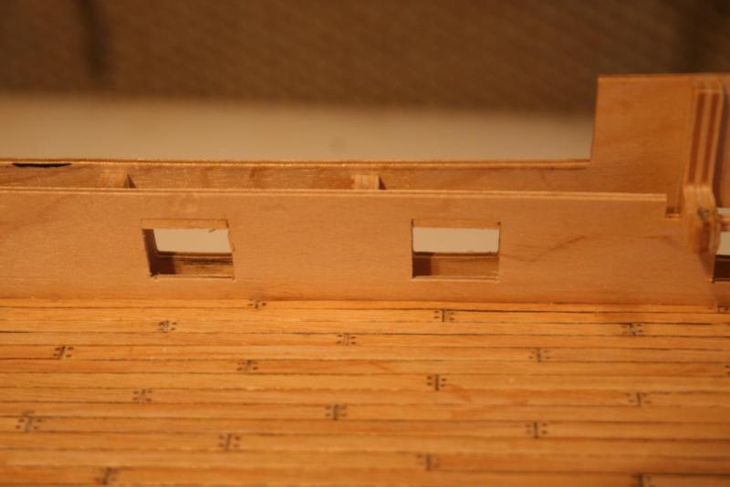
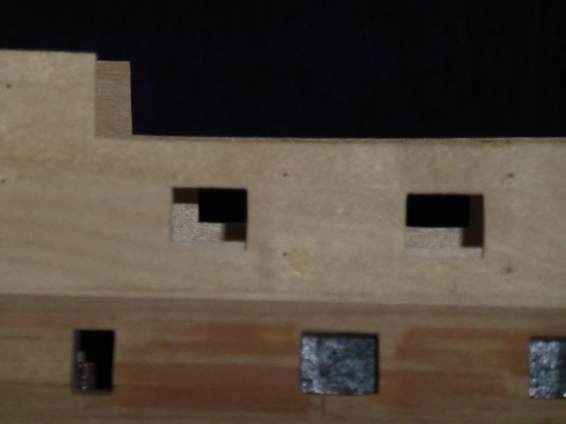
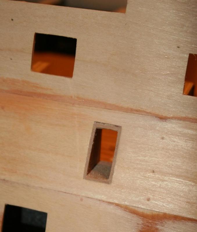
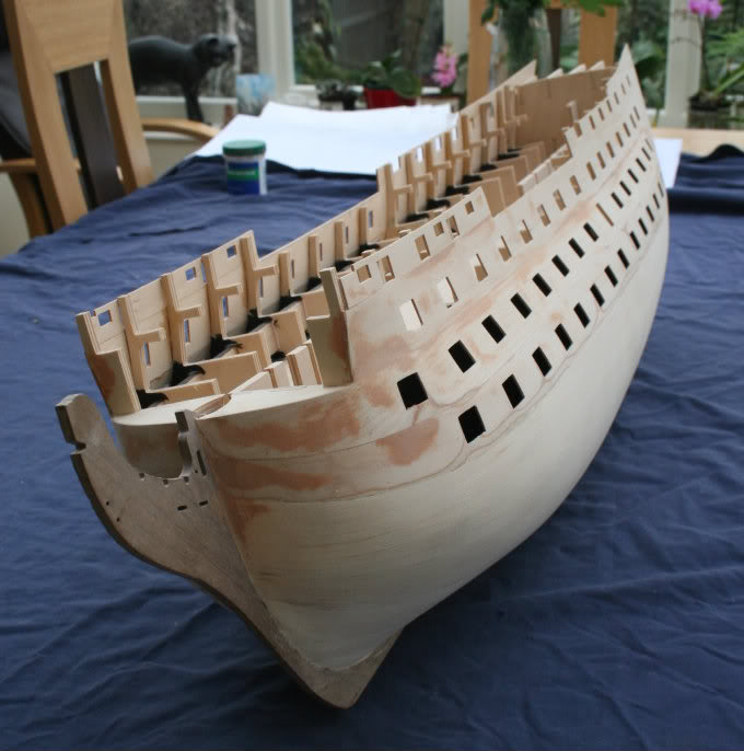
Hi Folks, To continue the story with the miss-aligned inner gun ports ……. The first step was to work out how much needed to be removed from each port. To do this a length of square bar was threaded through a pair of gun ports. The gap between the bottom of the bar and the bottom of the outer gun port was then measured. It ranged from 0.5mm to 3mm, averaging around 2mm for the majority. This measurement was then marked onto the pattern and the ply sliced with a scalpel. A ‘sabre’ saw with a reverse toothed blade (cutting on the pull stroke) was used to cut the ends. The final step was to cut and glue a strip of scrap ply into place. Not pretty, but job done and work can now progress with the lining. Cheers, Graham.

-
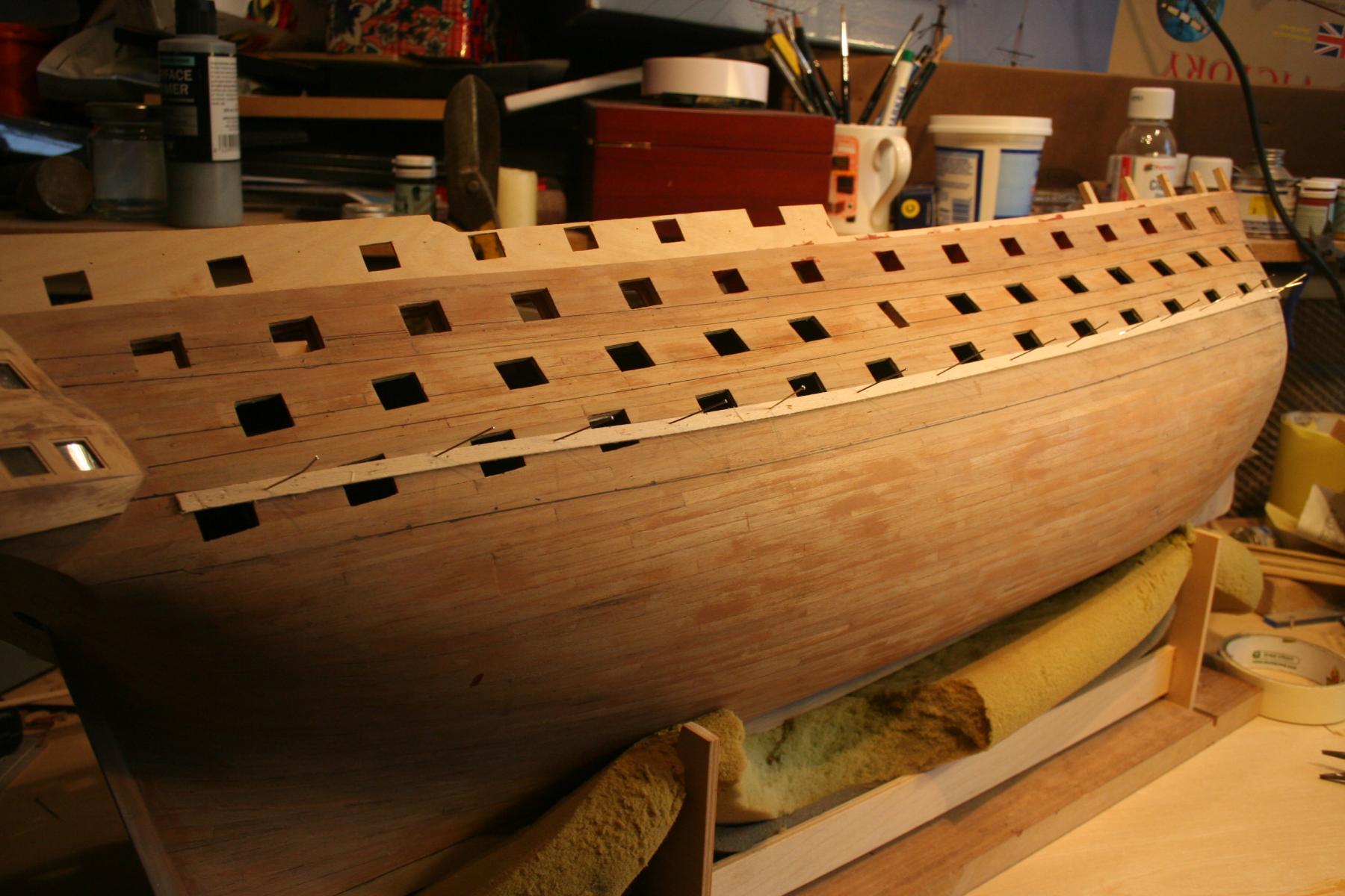
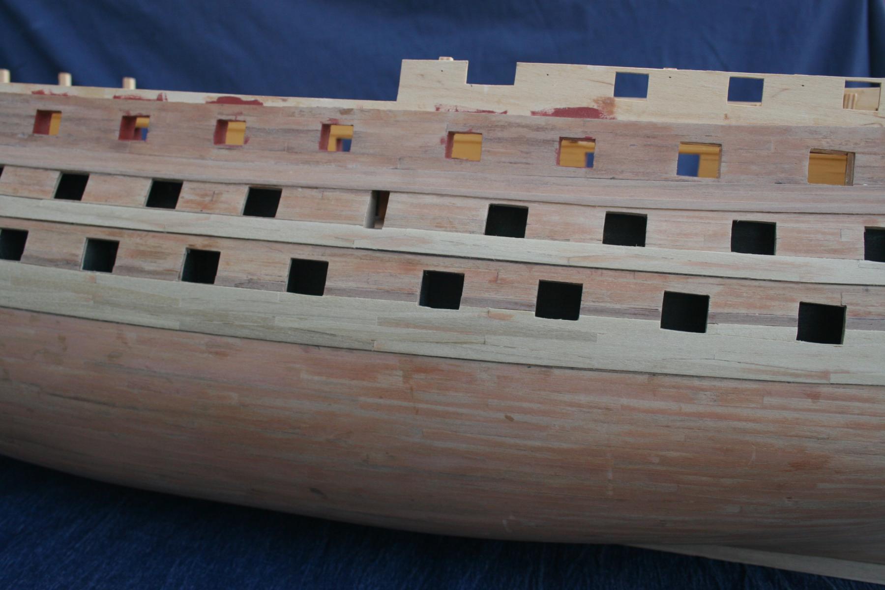
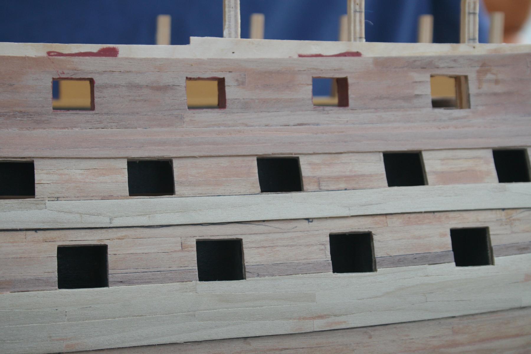
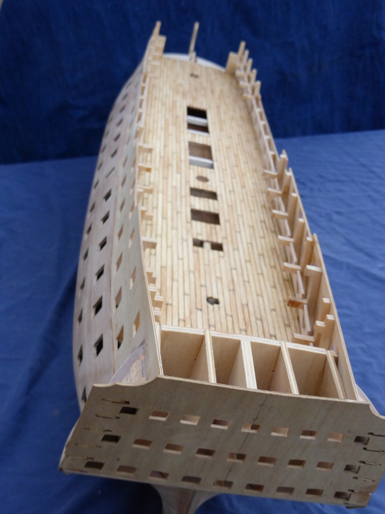
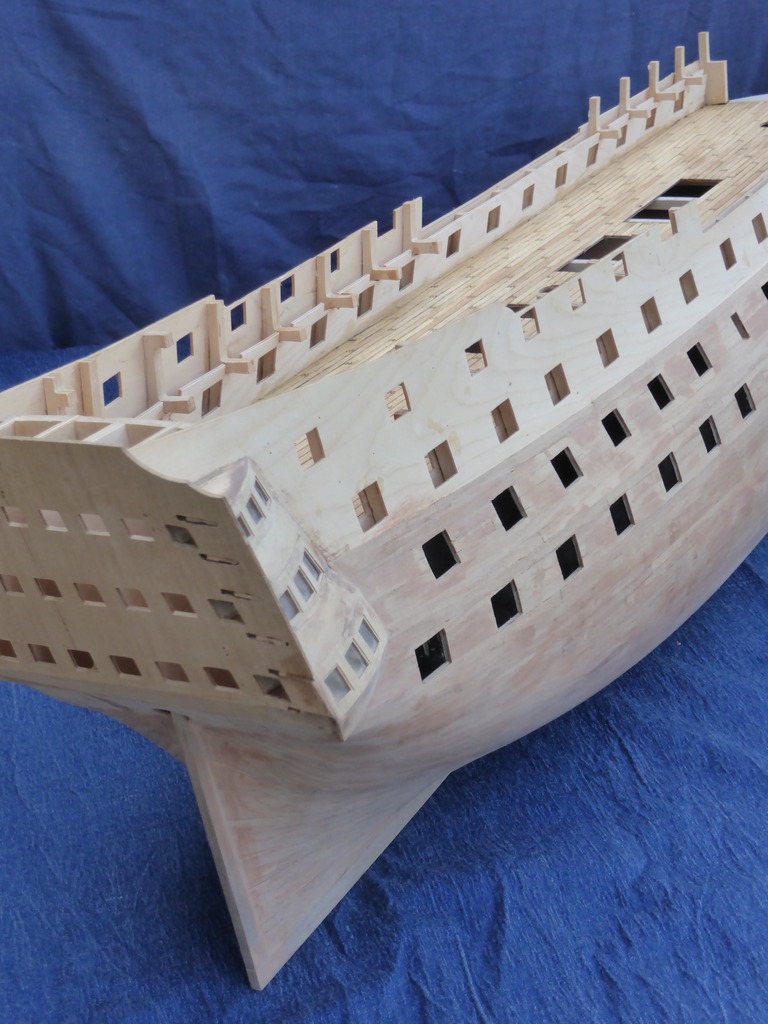
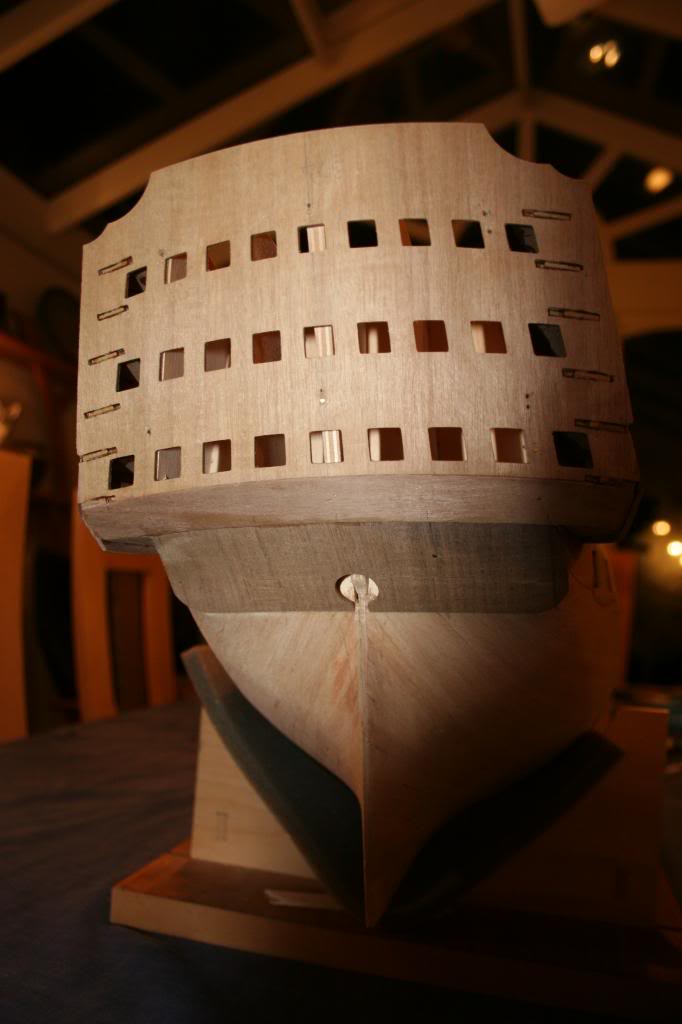
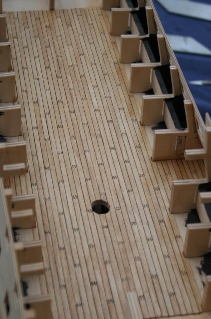
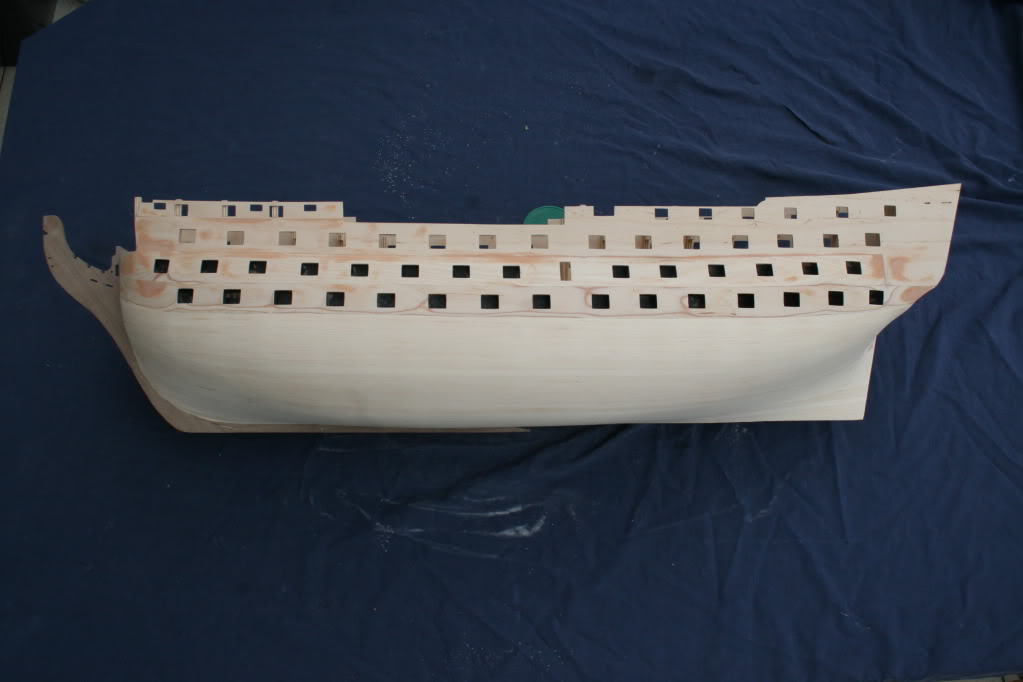
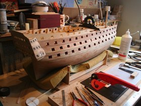
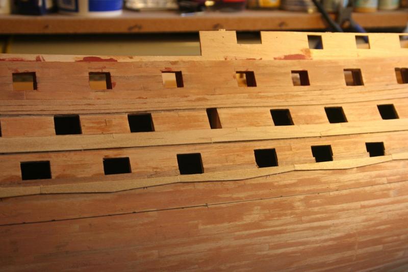
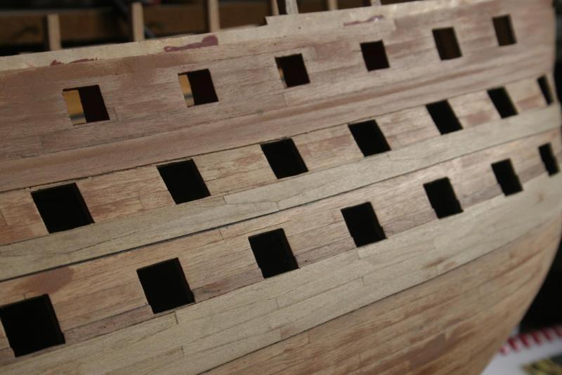
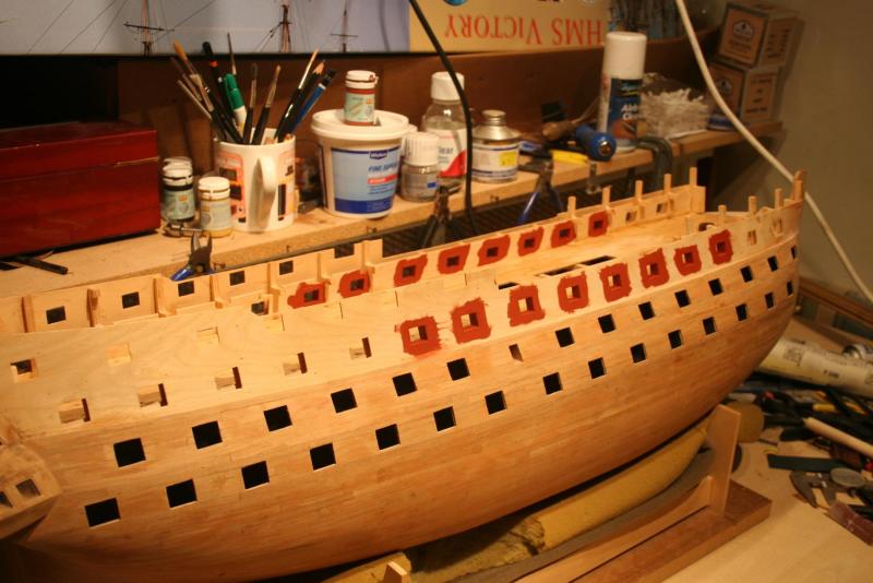
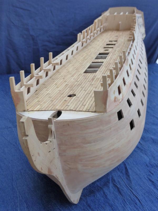
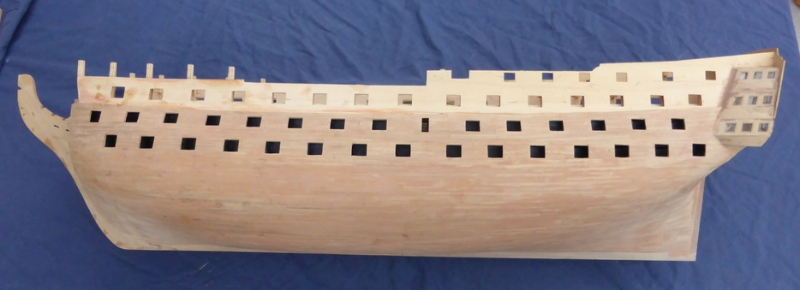
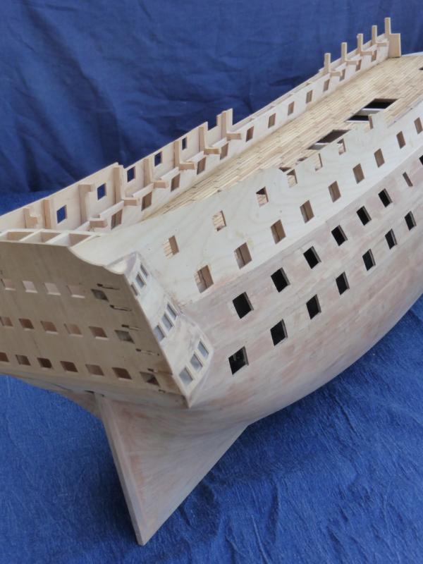
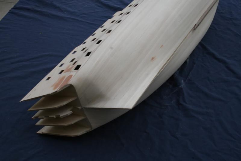
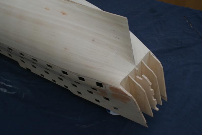
Hi folks, I set myself two short term goals a couple of weeks ago; to get this build log up to date by editing and uploading previous material, and to finish planking the upper gun deck including tree nailing. It was a close thing but both of these objectives were achieved. The planking and tree nails have now been refined to a smooth finish with a scraper and given the first of several coats of mat varnish. These photographs show the second planking of the hull. Unfortunately I omitted to photograph this work as it progressed. I decided to go the route of using short planks (127mm / 5”) as opposed to longer lengths and found this easier, gluing them in place (CA glue) and shaping the profile of any planks as required. Any minor gaps and imperfections were dealt with using a little wood filler. The hull has now been sanded to a good finish although I am expecting to have to give it a final going over once it’s been primed with grey primer once the wales have been completed. There’s plenty to do in between adding coats of varnish on the deck. Cannon barrels and carriages need assembling, plus preparing the various different styles of plank for each of the wales ( jigs made but not yet tested). This will keep me busy until the final coat of deck varnish has dried. Not until this is done can I tackle the problem of the miss-aligned inner gun port patterns. Note to self – read the excellent build logs produced by others more carefully! When I fitted the inner patterns they were carefully aligned horizontally. The patterns slipped so nicely into the spaces in the bulkheads, with the top edge level with the outer pattern that I assumed all was well ……WRONG! As these photos show, the inner patterns need to be dropped by almost 3mm before they can be lined. My plan is to cut out the excess from the bottom edge and then graft a new piece into the top. This will be easier than pulling the whole pattern out and re-fitting it, and the final planking will hide the evidence! Cheers for now, Graham.


-
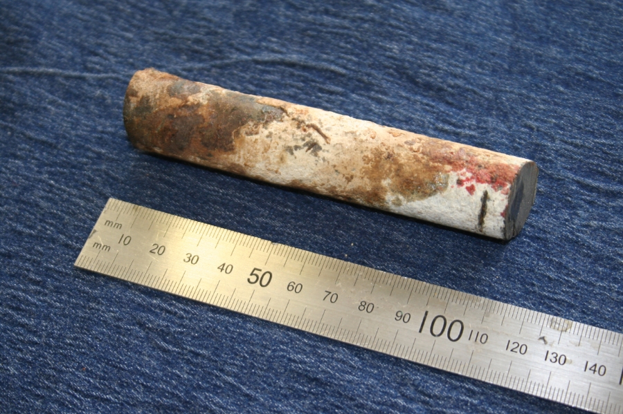
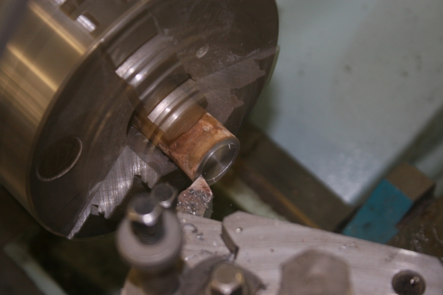
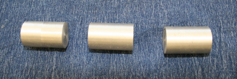
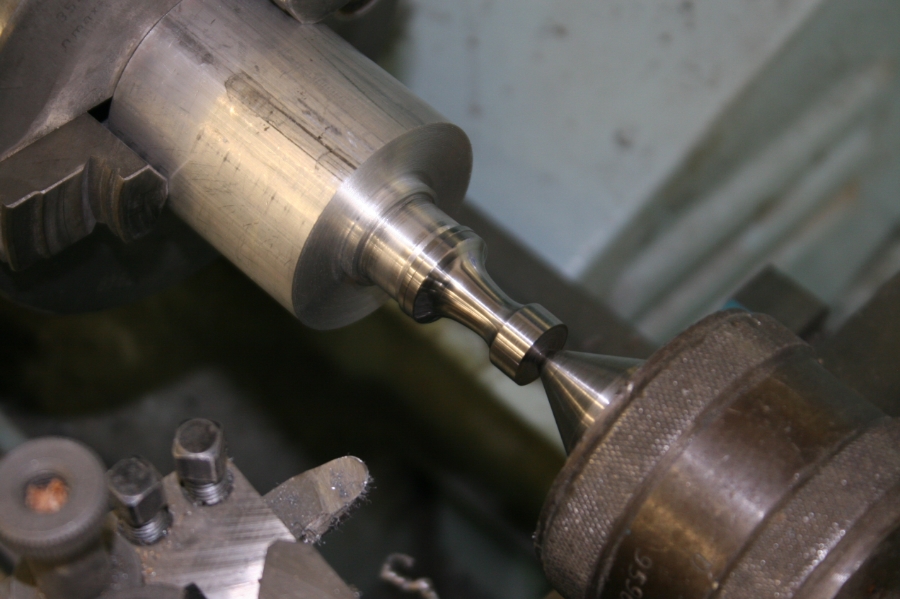
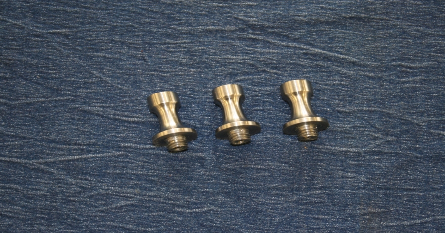
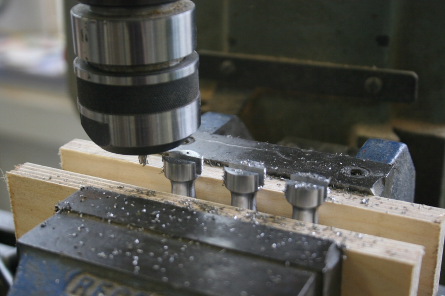
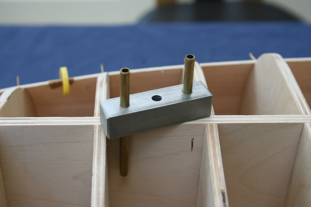
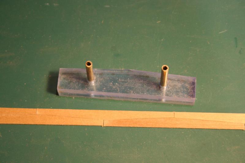
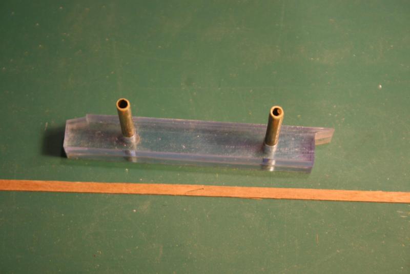
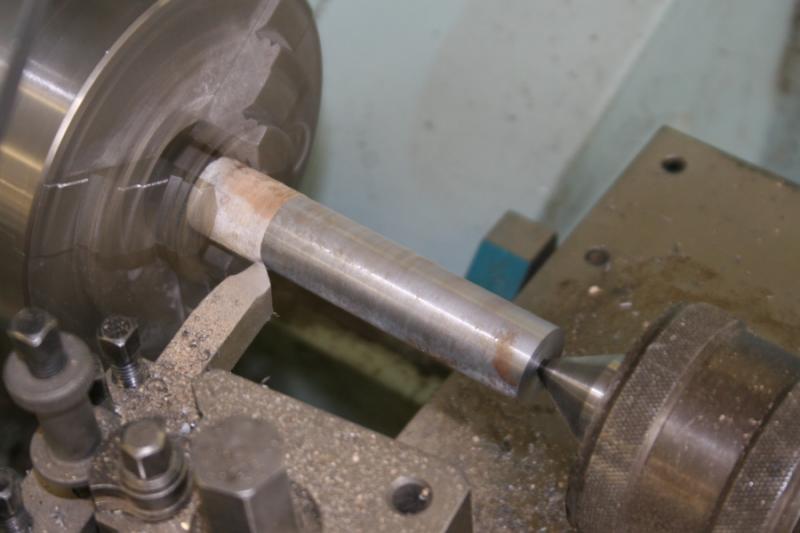
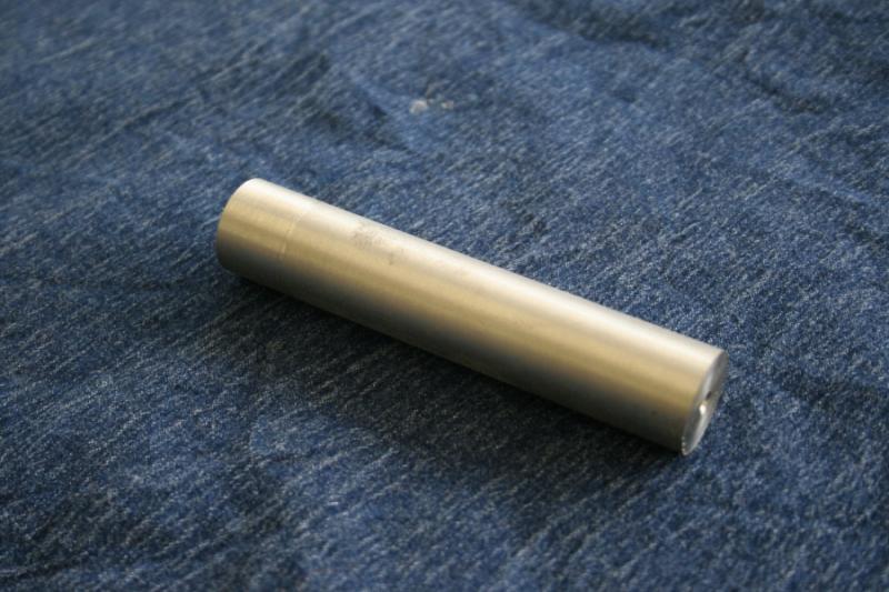
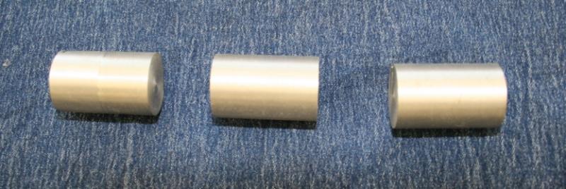
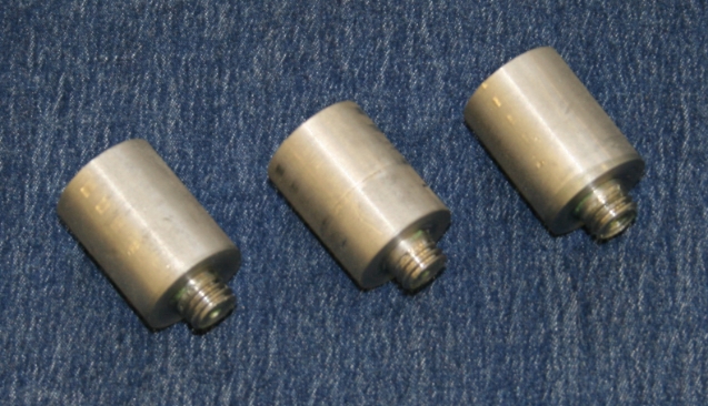
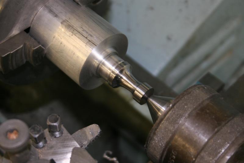
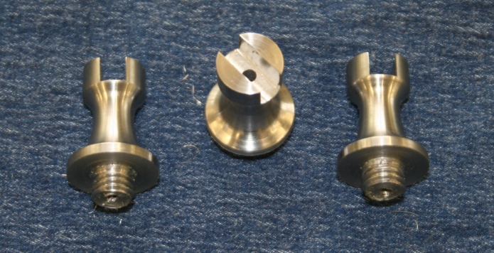
Hi Folks, The last of the three ’Victory material’ challenges is the construction of three ‘pedestals’ on which the finished model will be mounted. Final completion of the model is still a considerable way off – but retirement is probably going to strike before this and it makes sense to tackle the task while access to the workshop equipment is still possible. (well, that’s my excuse and I’m sticking to it…) There are a number of unknown factors that could affect this mini project: Will it be possible to turn the metal in the first place? – I’ve come across some metals in the past that have a skin so hard it knackers the cutting tool in seconds, and what kind of finish will it be possible to achieve? Only one way to find out. The rod as supplied…..pretty uninspiring, about four inches long and a little less than an inch in diameter. First job is to face off the ends of the bar. …..then skim the bar to remove the corrosion. First question answered – oh yes, it will machine. It cuts in a similar way to mild steel and is relatively soft …. The finished billet is then cut into three blanks… I’ve made the decision to turn the base of each column down and thread them M10 x 1.5 initially to enable each piece to be mounted on a mandrel for further machining, meaning I won’t have to hold the blank directly in the lathe’s chuck, and eventually to fix the pedestals to the wooden base. Mounted between the mandrel and a revolving centre, each blank is machined to profile with a round nosed tool. The final finish is achieved using emery cloth followed by 600 grade ‘wet and dry’, and finally the same grade of abrasive paper lubricated with a light oil. Just like turning legs for Windsor chairs, the first one is quite straight forward – its’ getting the others to match that provides the challenge! Last task is machining the slot for the keel to fit into, using a universal milling machine fitted with a 4mm slotting bit. The final slot was 6mm wide. The pedestals have been previously been drilled on the lathe to take the 1/8th” silver steel rods that will extend up into the tubes set into the hull structure (see my first ‘post’). Done and dusted…. Cheers for now, Graham


-
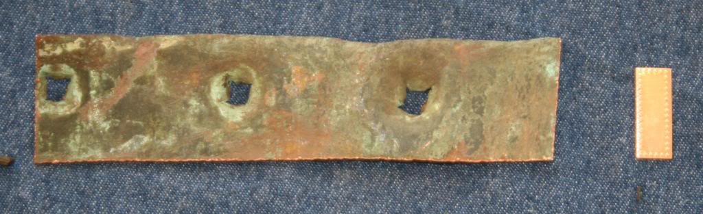
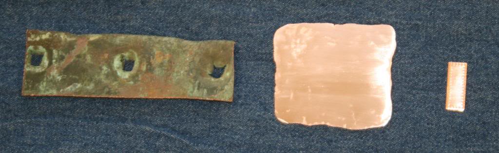
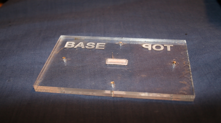
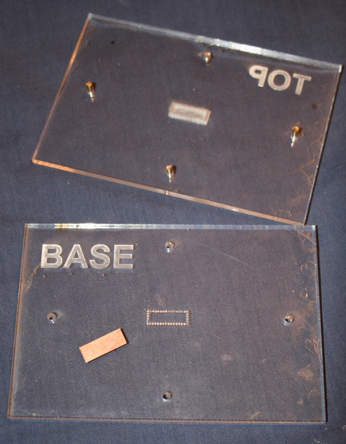
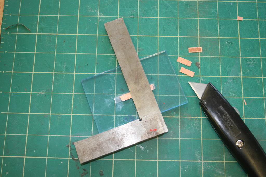
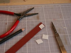
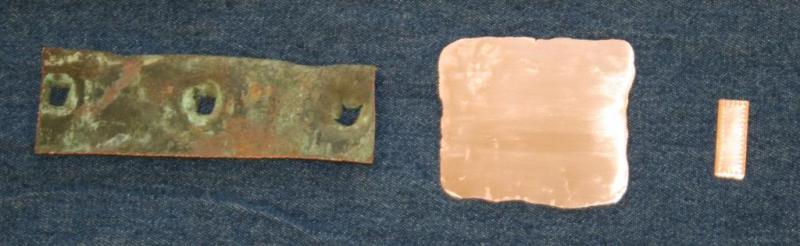
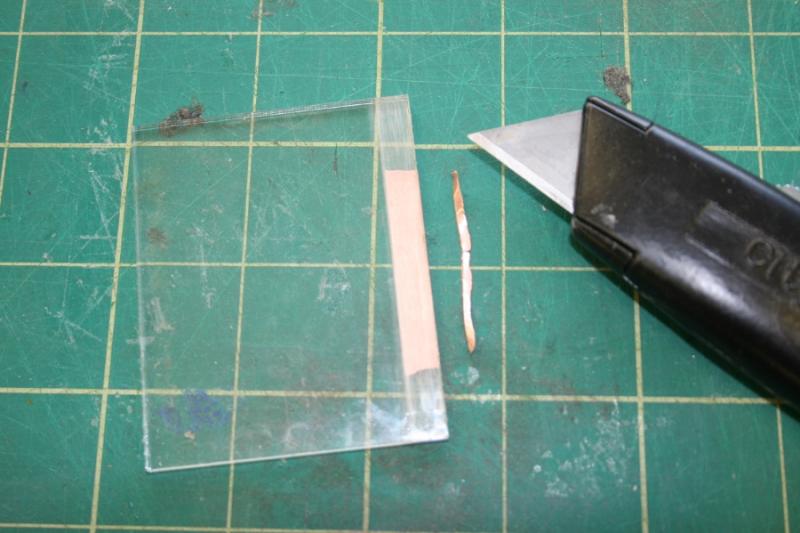
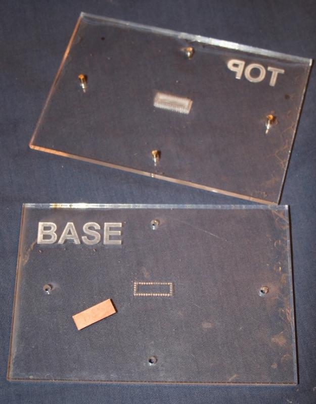
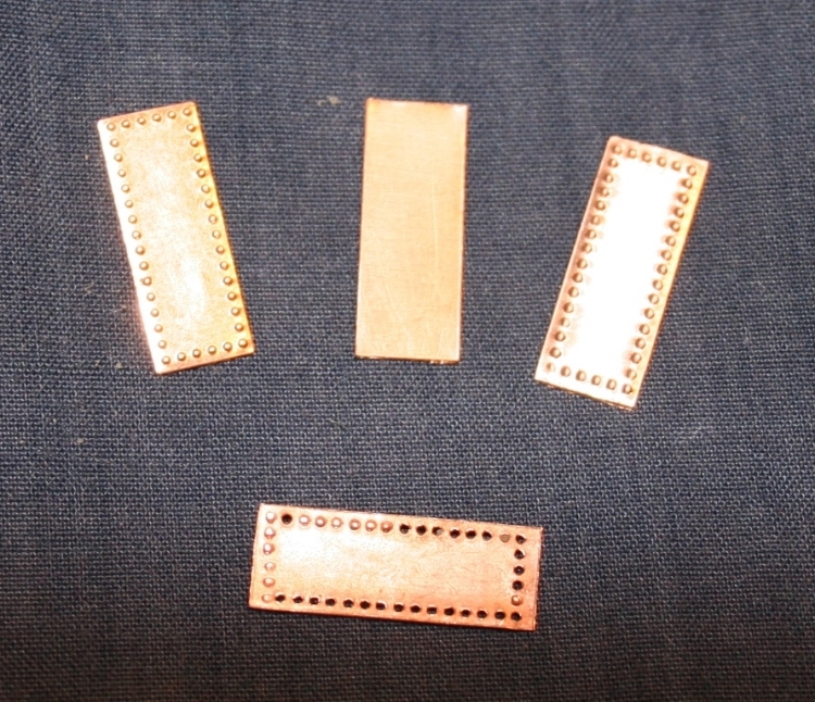
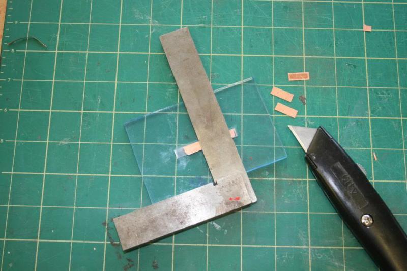
Hi Folks, The second challenge, the copper plates….. The scrap of copper I received was from the edge of a plate complete with fixing holes punched through. A small section was cut off making the remnant a bit more symmetrical. This will eventually be mounted on the display base. The off-cut was far too thick so I resorted to beating it by hand, hammering it to a closer match to the thickness of the kit’s plates. This required frequent annealing of the metal. The process resulted in a significant increase in surface area to the extent that instead of producing just a couple of plates I ended up with eight. The next step is to try and work out how to produce the simulated rivet pattern. First task was to cut the piece of copper into strips. ……this was achieved with a cutting guide and a sharp craft knife. Another guide, together with an engineers’ square, helped trim these strips to length. A jig was made to replicate the rivet pattern. Each indentation was produced by taping a short steel pin in through the top of the jig. The resulting plate is shown on the right, a blank in the centre, and an original kit’s plate on the left. The bottom plate was the first attempt where too much wellie with the hammer pushed the pin right through the copper! Cheers, Graham.


-
It all makes sense now - thank's David. I'm currently away from home, but your suggested modification will be the first thing I'll do when I get back to the 'shipyard'. Cheers Graham
-
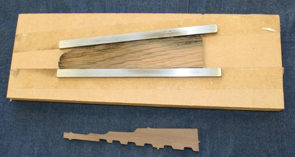
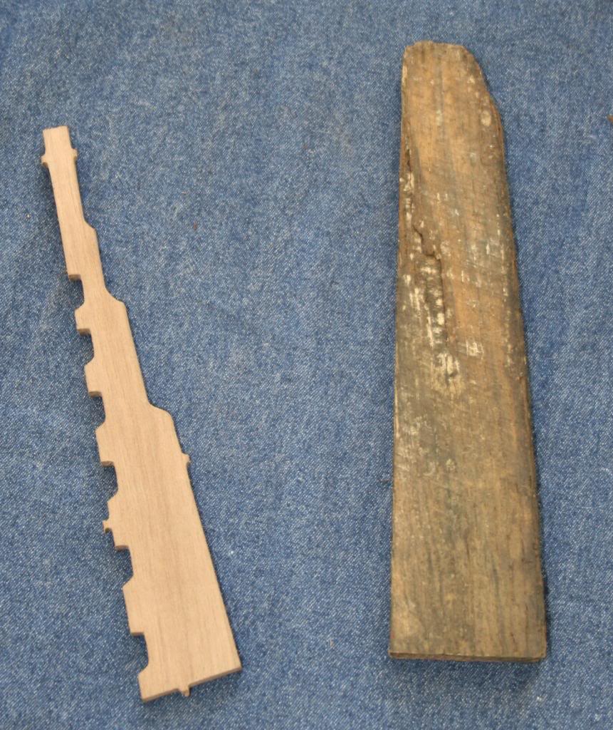
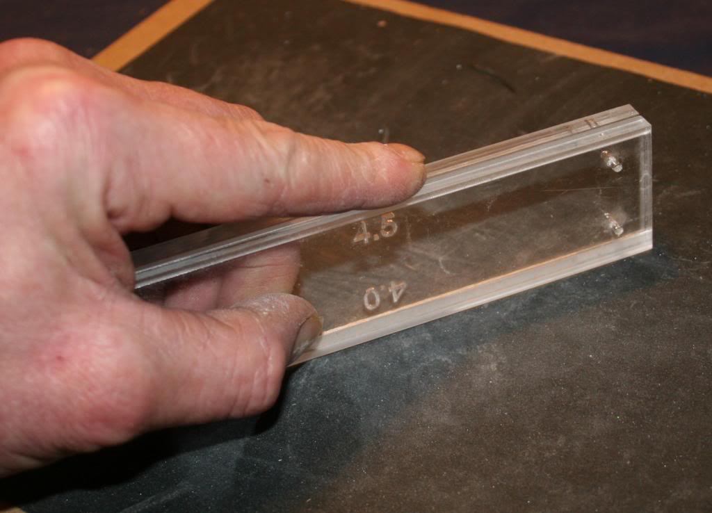
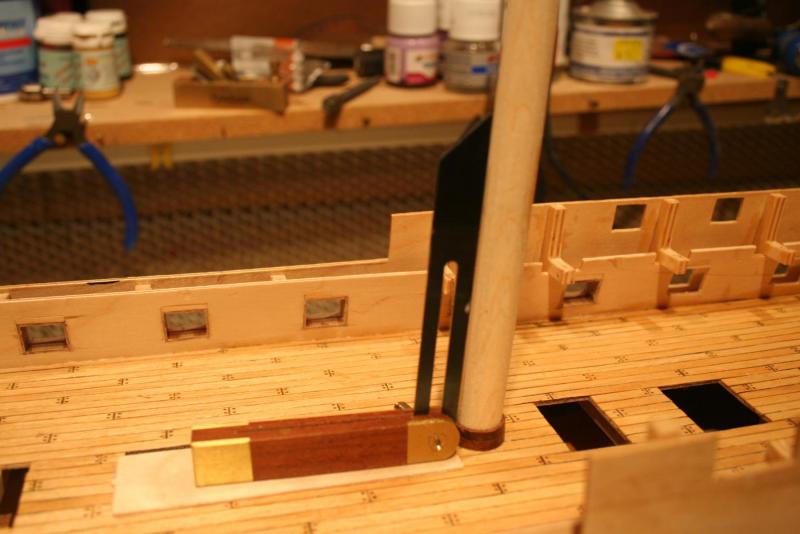
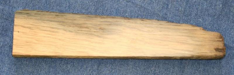
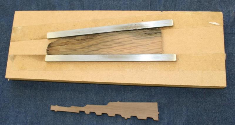
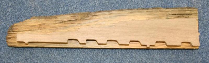
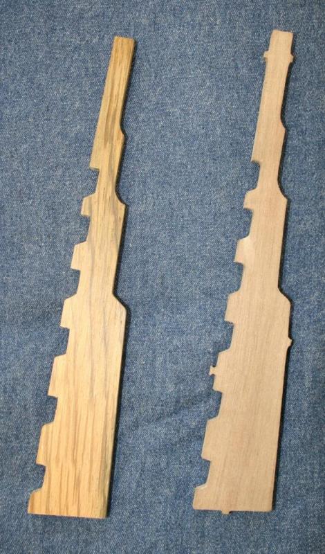
Hi Folks, The first of the challenges I chose to undertake was the rudder – to replicate the kit’s original piece, on the left, using the Victory oak. One side was cleaned up, the thickness then cut narrowly oversize with a band saw, and then the timber was sanded down to its final thickness of 5mm using the jig. The aroma of old oak (with a hint of tar?) added to the pleasure of the task. It was going to be a tight fit! After transferring the outline the shaping was done using a powered fretsaw and needle files. Job done! The finished rudder is mostly copper clad with the top section painted black – I’ll probably leave some of this upper area unpainted and just apply matt varnish; but that’s way off in the future…. Next – the copper plates. Cheers, Graham

-
Hi, Mort - the saw I went for is listed as a Zona sabre saw. I need it to sort out a gun port problem so looked for a saw with a blade that was slim, thin, had no 'back' rib and had fine teeth that will not cause the micro ply to splinter. I went for the version that is supplied with three blades, one of which has reversed teeth so cuts on the back stroke and this will probably be the one I'll use. Not an expensive option either which is always a bonus for a self confessed tool addict. I hope this does not break any site rules - if it does could someone let me know? David - thanks for your kind evaluation of my work. I'm certainly taking my time! I tried to reply to your p.m but somehow managed to delete it and lose the 'reply' button when I tried to send it. Even the link received on my phone chastised me for having the audacity for trying to use the link! (don't you just love technology!). Just to check - we're referring to parts 276? It's easy enough to remove. I'm a regular reader of Robert's build log but missed this. I fitted it as I am constructing the Trafalgar version. Looking forward to hearing the reasons as to why it's best fitted later. Cheers, Graham
-
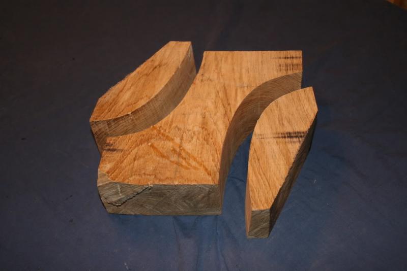
Hi, Seasons greetings to all - I hope Santa has responded to the hints you may have been dropping recently as he (she) did for me - a quality razor saw that will help me rectify a minor issue with the upper gun deck inner bulwark gun port patterns. I'll explain more when I get this build log in sync with actual progress. Meanwhile, to continue the story..... Where do I start? Ever since I began this build I’ve had a nagging thought in the back of my mind – wouldn’t it be great to find a way to incorporate a piece of the original ship into the model. Did a bit of research (hours of ‘googling’) - but to no avail… ….then ….. There I am at an ‘exhibition of Contemporary Design’ (craft fair!) playing the dutiful ‘Sherpa’ (chauffeur, guide, provider of credit card and carrier of purchases) and found myself having a chance discussion with a stallholder that culminated in an absolute RESULT! To cut a long story short I am now the proud owner of a Certified piece of oak from the good ship herself from which I aim to make the model’s rudder. It gets even better. I also have a small scrap of the original copper hull plating and a piece of iron rod also from HMS Victory. I now have three challenges- Fabricating a rudder for the model from the piece of oak. Replicating a couple of the hull plates and use them in the model’s copper cladding. Incorporating the iron as part of the three pedestals that will eventually support the completed model on its display stand. Cheers for now, Graham
-
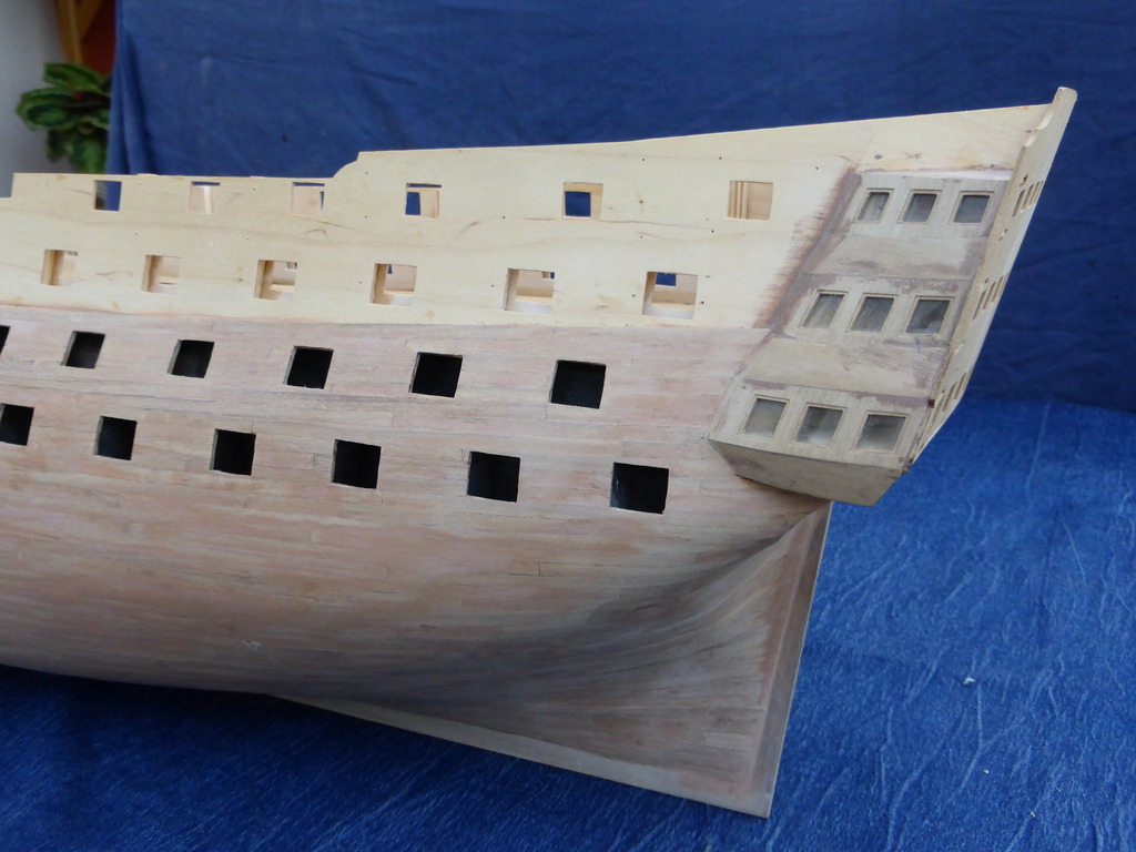
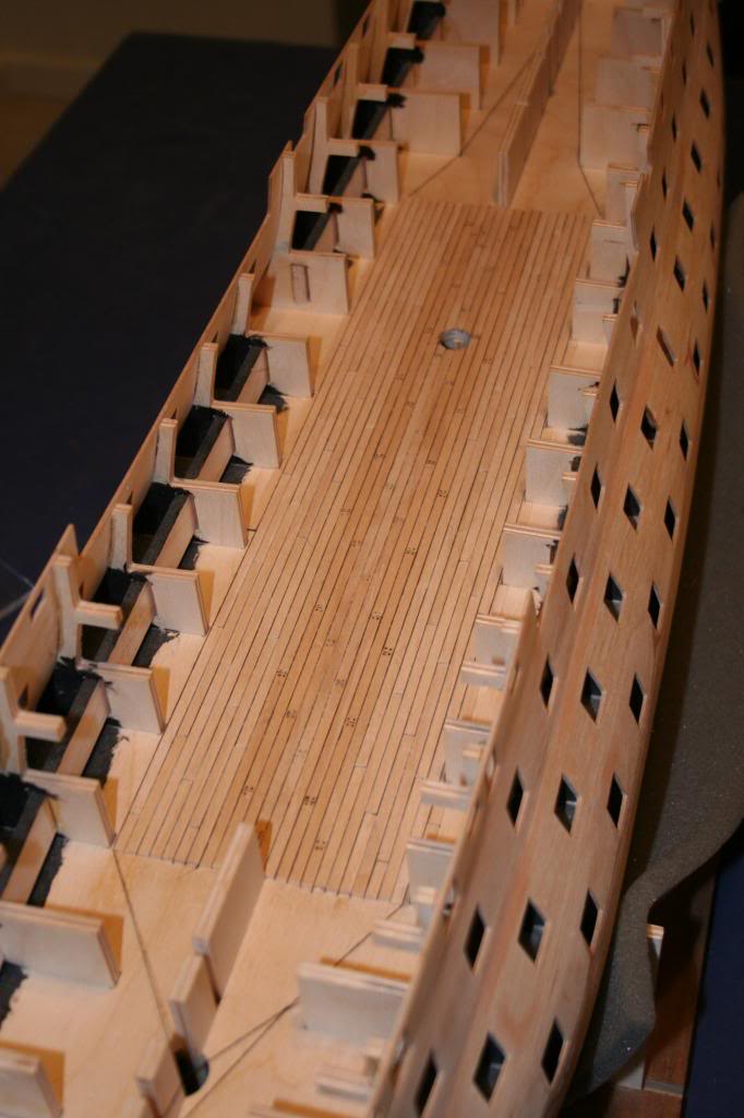
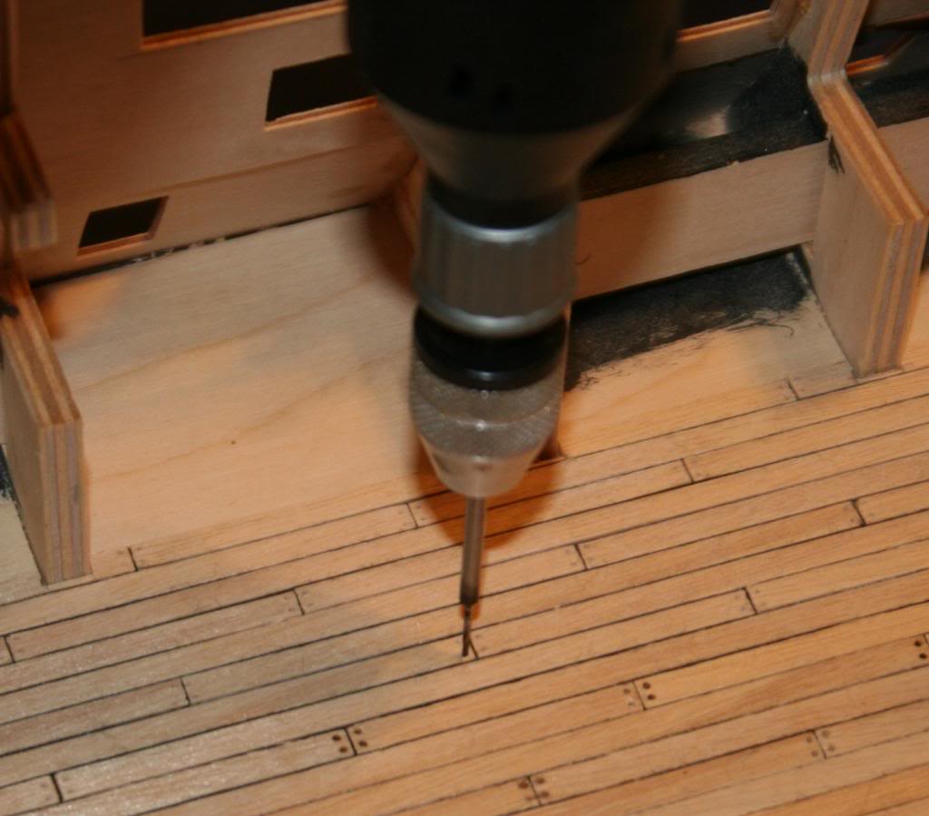
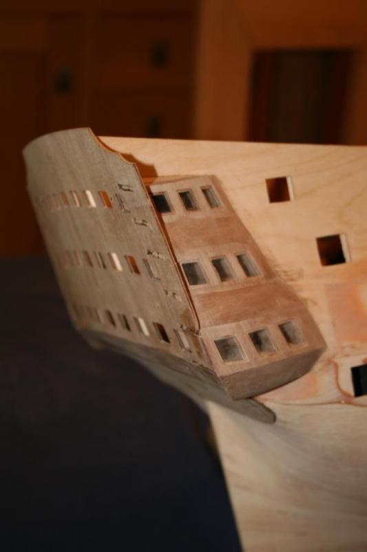
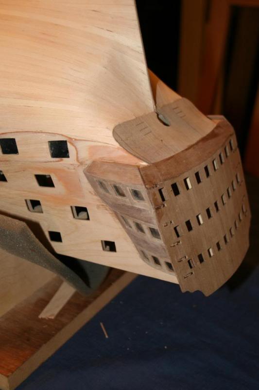
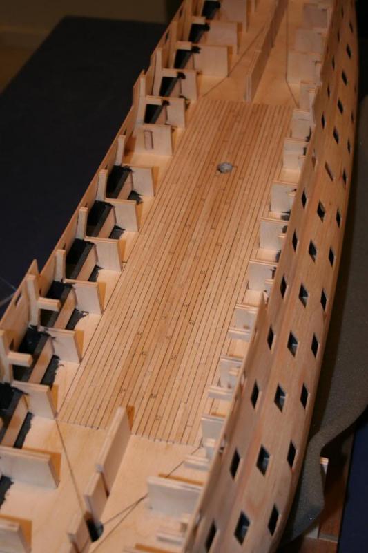
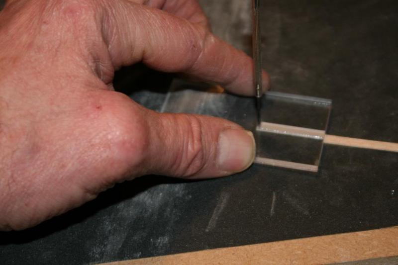
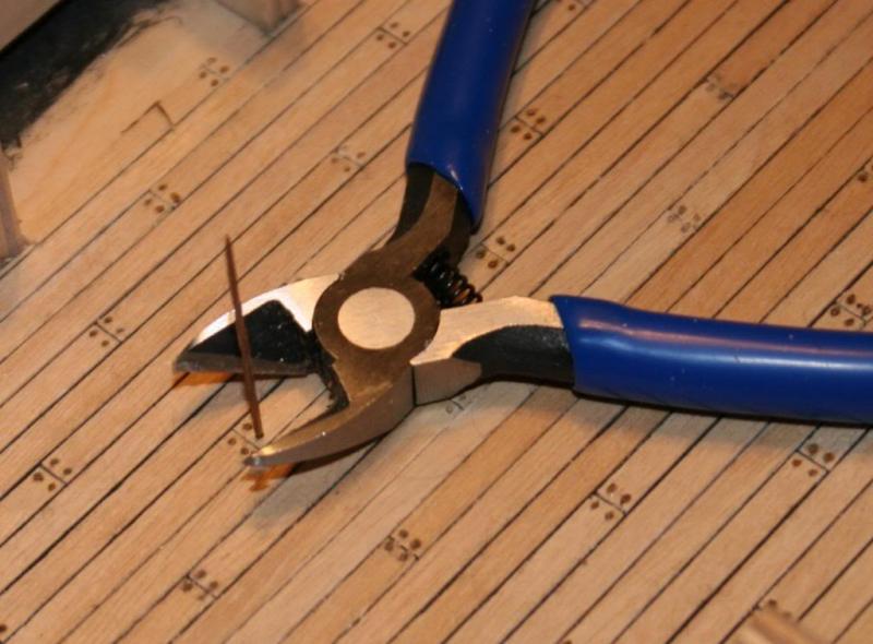
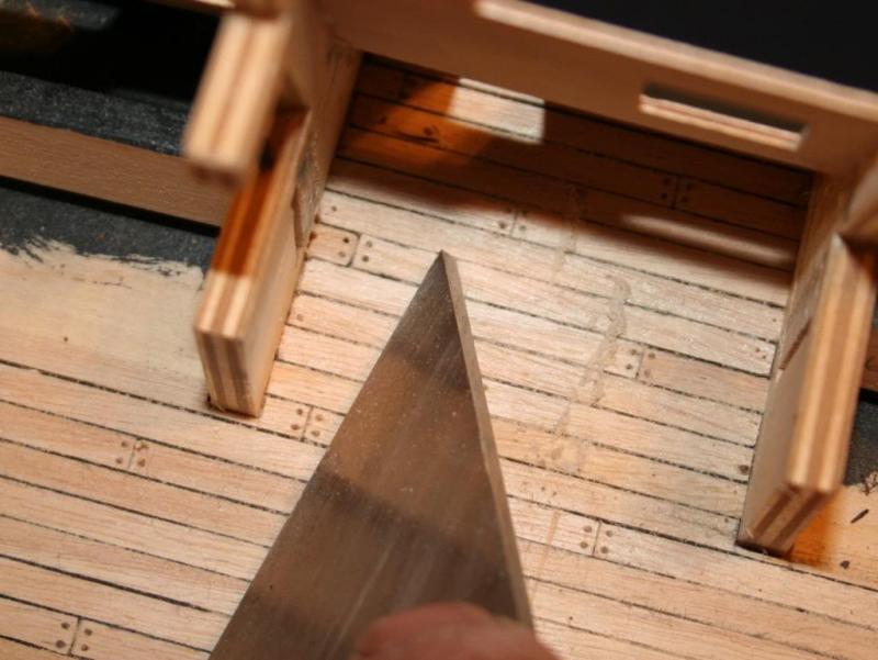
Hi, Construction of the Quarter Galleries went as per the instructions, which proved to be very accurate: ‘Time and care will be required…..’ Oh yes, and as many arms as an octopus wouldn’t go amiss! However, the effort was rewarded by the results and I must admit that that there’s much satisfaction, and a sense of relief, once the juggling of components is finished. The upper stern counter pattern fitted easily, and to achieve the slight concave curve on the lower stern counter pattern I decided to increase its pliability by wetting it and then zapping it briefly in the microwave. I then left it, suitably supported, under a cylindrical weight to cool down and fully dry out. The photos show the result. The next task was the middle gun deck planking. I wanted to simulate the treenails and the caulking between the planks. I’ve followed the various debates relating to how appropriate it is to have them on model of this scale but I like them and feel they are worth the effort. Little of this work will be visible once the hull is finished but it seemed like an ideal opportunity to try out different techniques in preparation for later in the build. For the caulking I went down the black thread route, running a line down each edge of the plank runs and also gluing a short length of thread to one end of each plank where it would butt up to the next. One minor problem was the side edges of the planks which were often slightly beveled, a bit rough or marginally wider than 4mm. Fine ‘wet and dry’ glued to a piece of MDF and a sanding aid sorted this out. The most successful method of simulating the treenails started with the marking of their positions on the ends of each plank. Another jig and a small watchmaker’s screwdriver ground to a point enabled the positions to be impressed, and these marks acted as the equivalent of centre punch marks on a piece of metal – enabling a 0.5mm PCB drill bit in a mini-drill to line up and make the hole without slipping. This drilling was done after all the planks had been glued down. The treenails themselves were made from slithers of teak veneer. These were dipped into PVA glue, then pushed into place and cut almost flush with a pair of side cutters. The adjacent photo shows the last one going in. Once the glue had had a chance to fully set any remaining protruding material was sliced off with a sharp chisel. Sanding the decking risked catching the caulking thread so a smooth surface was achieved by careful use of some scrappers. After any dust had been brushed or vacuumed the surface was sealed with a coat of matt varnish after which it proved safe enough to resort to fine glass paper between each of the subsequent two coats of varnish. The mast sleeve was fitted after the varnishing was done to make sanding the deck easier. To get the sleeve to bond to the varnished surface I resorted to rapid drying epoxy resin. These photos show the lining of the entry ports. The next stage, and one I’ve been looking forward to, is the second planking. Following the advice of other builds on this site (thanks to all!) I’m going to replicate the 30’ plank lengths. If my maths is right this makes a full plank 127mm long, with an overlap that works out at 2 inches. (apologies for mixing units of measurement – that’s just how my old brain works these days!) Cheers for now, Graham.


-
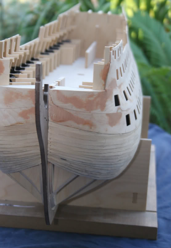
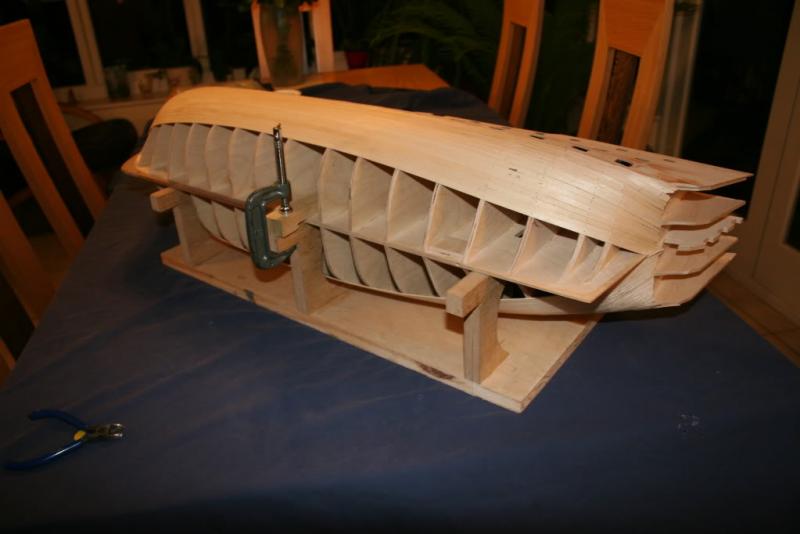
First Planking With the bulkheads set and the ply gunport patterns all glued in place the chamfering of the bulkheads were given a final ‘tweak’ prior to starting the planking. To help with this, and with the earlier shaping of the bulkheads, I put together a jig that held the model securely on its side. I found this helped with resisting the forces exerted when pushing the temporary pins in and could be used for the majority of the hull. Following the advice given on this site concerning tools I invested in a pair of plank nippers. A bit of practice quickly proved what a useful piece of equipment these are, although I wouldn’t use them on the ships boats as the inside of the first planking of these is visible and the small groves the nippers leave would show. I have to date finished the first planking of the launch and some of the second planking. The first couple of planks are laid without any need for tapering but to avoid forcing the initial planks into place I started by putting ‘stealers’ at both the bow and stern. For the most of the planking the procedure was: • Trim the plank end to match the stem • Taper the top edges (with a slight undercut as well) for the first and last four or so bulkheads by anything from 1/3rd to 2/3rds of the plank’s width as determined by offering the plank up to its position. Leave plenty of overlap at the stern for later trimming • Holding the plank in place pre-drill or bradawl (I used a map pin for this) pin holes through the plank and into a manageable number of bulkheads. (4 – 5 usually) • Apply glue to four or five bulkheads at a time where there will be contact with the plank • Apply glue to the matching length of the edge of plank • Pin plank to bulkheads, and use clips between bulkheads to ensure good edge to edge contact. Off-cuts of planking make great glue applicators! Keep telling yourself – it’ll be fine when its sanded……..it’ll be fine when it’s sanded…. A few ‘stealers’ where required, especially at the stern, but these were no problem to cut to fit the gaps. Sanding the hull to shape turned out to be more straight-forward than I anticipated but as it is a messy job the hull had to be transported to work for the task – you get some funny looks walking across the car park with one of these tucked under your arm! My only regret was filling blemishes with filler that was a bit darker than it could have been which tended to emphasize defects but as the whole lot gets covered with the second planking and subsequent painting it does not matter too much. Next installment - juggling the components that make the Quarter Galleries. Cheers for now, Graham


-
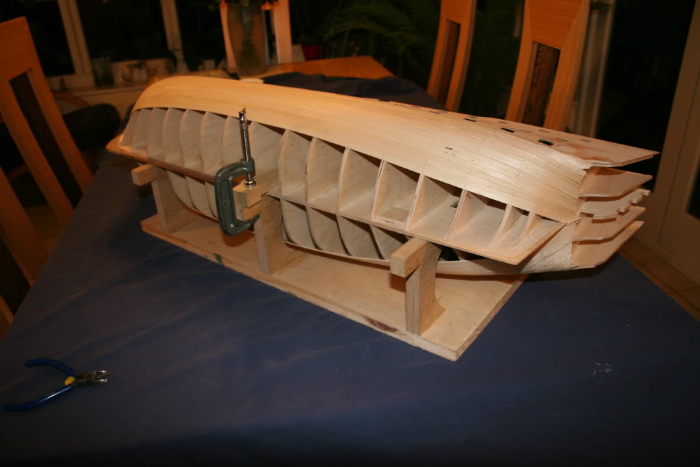
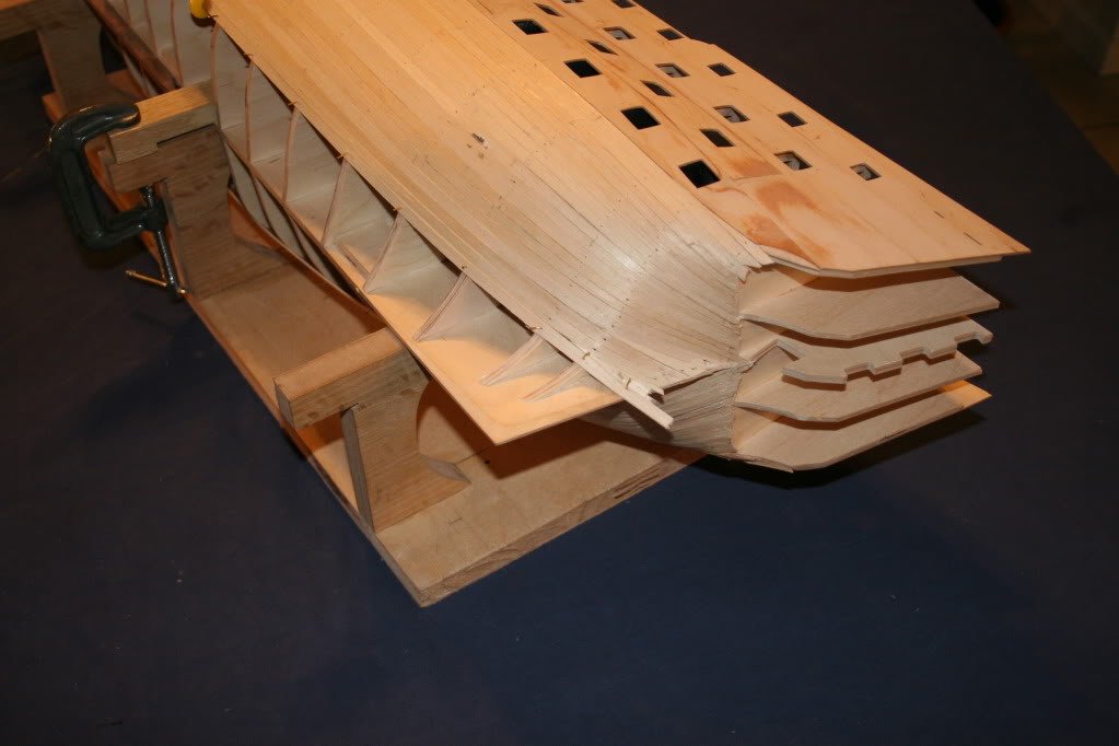
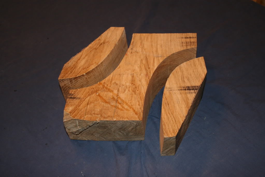
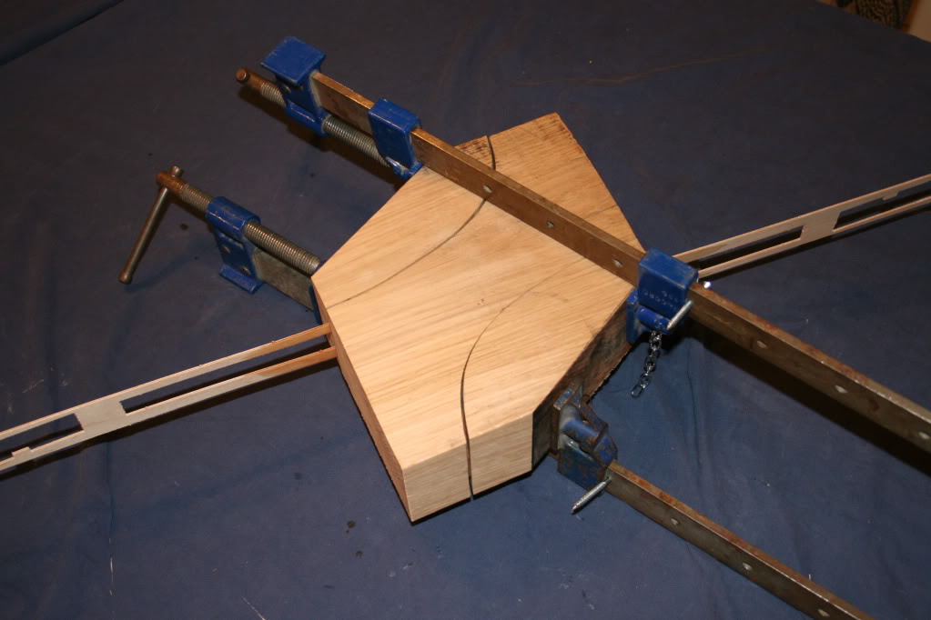
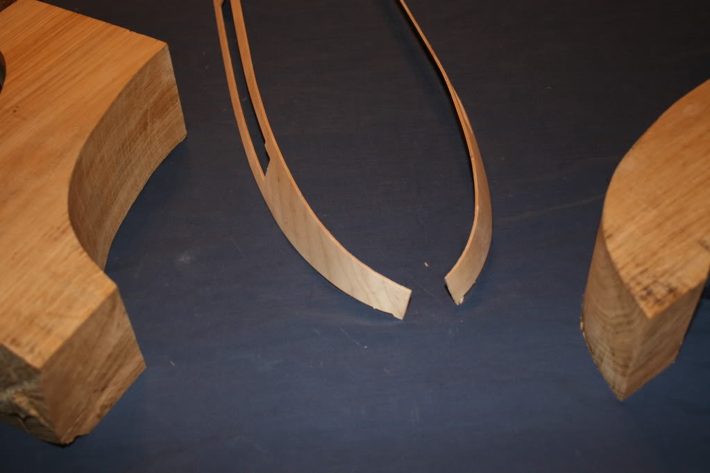
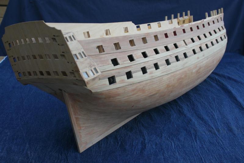
Hi Folks, Yet another Victory model under way. My kit was an anniversary present (25 years!) from ‘the Boss’. I first became aware of this model through the pre-issue information in a popular monthly magazine but had to dismiss the idea due to its cost. When it was suggested as a possible gift I didn’t need asking twice. The early stages of this build were originally shown on another website that unfortunately had to close down. I think it only fair to point this out as the rate of progress this build log will initially show will not be truly representative. Progress has been sporadic in the least. To be honest it’s taken me the best part of six years to get to where I am now (planking the upper gun deck) – life, work, other projects etc. all conspire to hold up progress. Initial construction was fairly trouble free, with the exception of an asymmetrical bulkhead 15. Dry assembly showed where the problem was so a new one was fashioned from some scrap ply I had lying around the workshop. The next challenge was drilling the holes in the keel for mounting the model later. I decided to insert 1/8th diameter brass tubes, with ply re-enforcement where needed, and to use steel pins to locate it onto a display base (one day!) To do this accurately it made a drilling jig based on a traditional design I use at work. Chamfering the bulkheads was one task I was not looking forward to, and it was at this point I discovered the value of websites such as this. Black felt pen lines on the back edge of the bulkheads that needed shaping ensured that I did not go beyond the profile. Concerned about how the lower ply gunport patterns would bend around the bow I cut a block of timber to fabricate a press forming tool. A card template was cut to match the shape of the bow and this was then transferred to the top of the block and band-sawed. The double cut design allowed both sides to be shaped at once. The ply was soaked for an hour, sandwiched between the blocks and left clamped for a day. The photo shows the result of a test run using waste from the gunport ply sheets. The strips were still slightly damp and pliable when removed from the former 24 hours later. With hind sight this was definitely ‘over kill’ and I probably wouldn’t resort to this method again, but it did the job! Details of my experiences with the first planking will follow…….. Cheers for now, Charter33.


-
Hi Robert, Your work is superb and a genuine inspiration. Your rate of progress is also most impressive. It has certainly helped encourage me with my build of this fine ship. Time, I think, to introduce myself formally on this site, and start to share my own experiences of the challenges this kit provides. Keep up the great work! Graham
-
Quite simply outstanding! Superb work, Heinz. Thank you for sharing it with us. Graham
-
Hi Rob, Yes, do it, not weird at all! I'm also building this model and through pure chance managed to get hold of a certified piece of the old girl herself and now have a complete rudder in original oak. I could smell the tar as I worked it. I am enjoying following your build - keep up the good work! Graham
- 295 replies
-
- 1
-
-
- victory
- caldercraft
- (and 1 more)