HOLIDAY DONATION DRIVE - SUPPORT MSW - DO YOUR PART TO KEEP THIS GREAT FORUM GOING! (Only 13 donations so far - C'mon guys!)
×


Charter33
-
Posts
455 -
Joined
-
Last visited
Content Type
Profiles
Forums
Gallery
Events
Everything posted by Charter33
-
Thanks' for the additional tips, Steve. The white vinegar is already in the workshop, the Birchwood Casey 'Brass Black' due for delivery early next week, as are the brass wire brushes for the Dremel which I hope will remove any traces of C.A. adhesive from the pivot rods (?) and the breach rings. Cheers, Graham
-
Thanks' Hornet - found it on ebay as you suggested and an order has been placed. I'll have a go and see how it comes out. Cheers, Graham
-
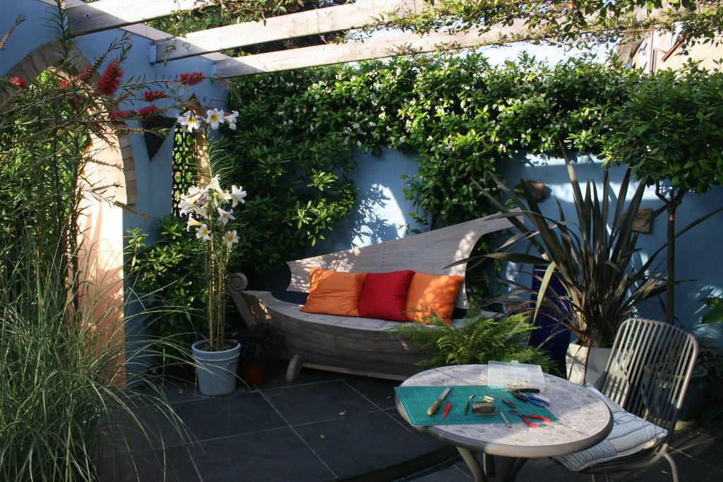
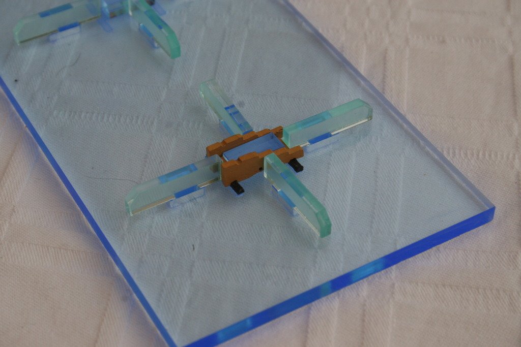
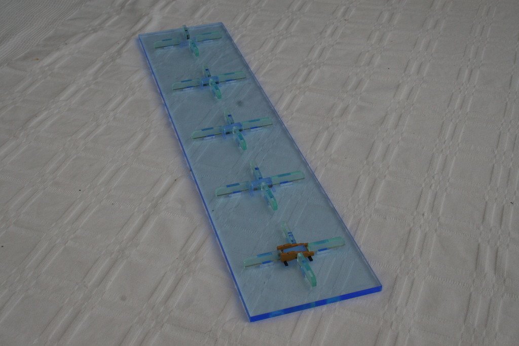
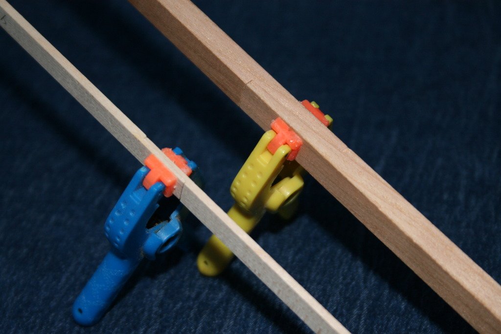
The hottest and longest day of the year. With the ‘shipyard’ inside the house uncomfortably hot a little ‘Al Fresco’ modelling was called for……. With the scent of jasmine wafting over the improvised work bench, and a cold beer, life’s good …. and this picture was taken just after 8.30pm with the temperature still in the high 20s. I came up with this jig to help me to construct the gun carriages – this is the test of the first of many to be assembled. The four elements surrounding the carriage slide up across into place and keep the parts aligned and 'square' while the glue dries. The jig will allow five to be assembled at once. Reliance on jigs has been made more necessary as recent medical treatment has left my fingers numb to the extent that I know I’m gripping something if I can see that I am. I’ve been assured that this side effect will eventually go but it’s very frustrating at times. Finally a little trick to clean up the carriage wheels – mounted two at a time on the grinding disc mandrel of a Dremel and lightly rubbed on a sheet of glass paper. Cheers for now, Graham.
-
Thanks' for the info Nick. You're right - using the airbrush can be a lot of messing about. I'll act on your advice and try hand painting first. I'm enjoying your Confederacy log - keep up the great work! Cheers, Graham
-
Hi, I'm a novice with the airbrush but am hoping to use one to apply the matt black paint to the cannons of my Caldercraft Victory. Has anyone had experience of spraying with Admiralty paints? I'm guessing that it will need to be thinned down - any suggestions as to the right mix? 20% water? 50/50? Any advice gratefully received. Cheers, Graham
-
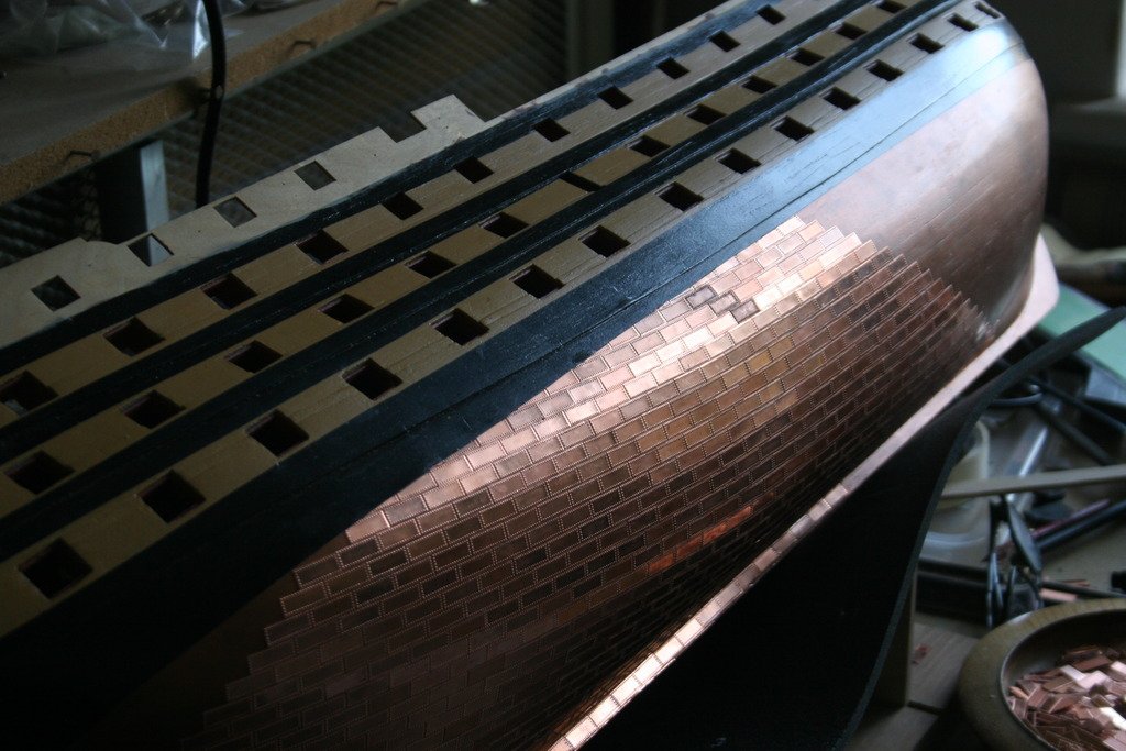
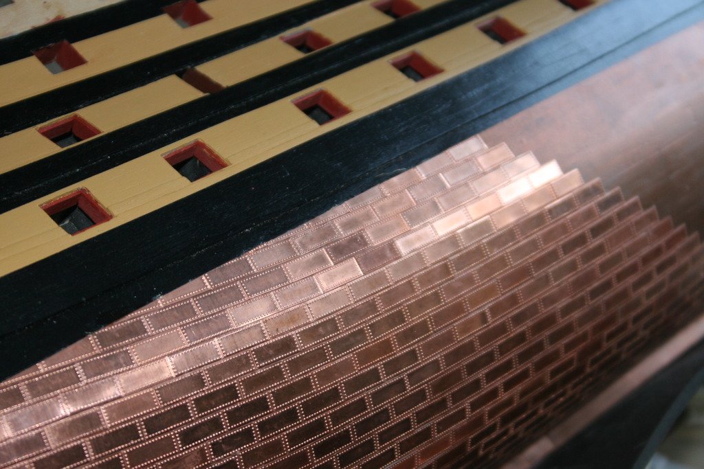
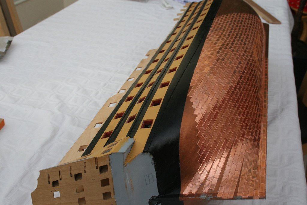
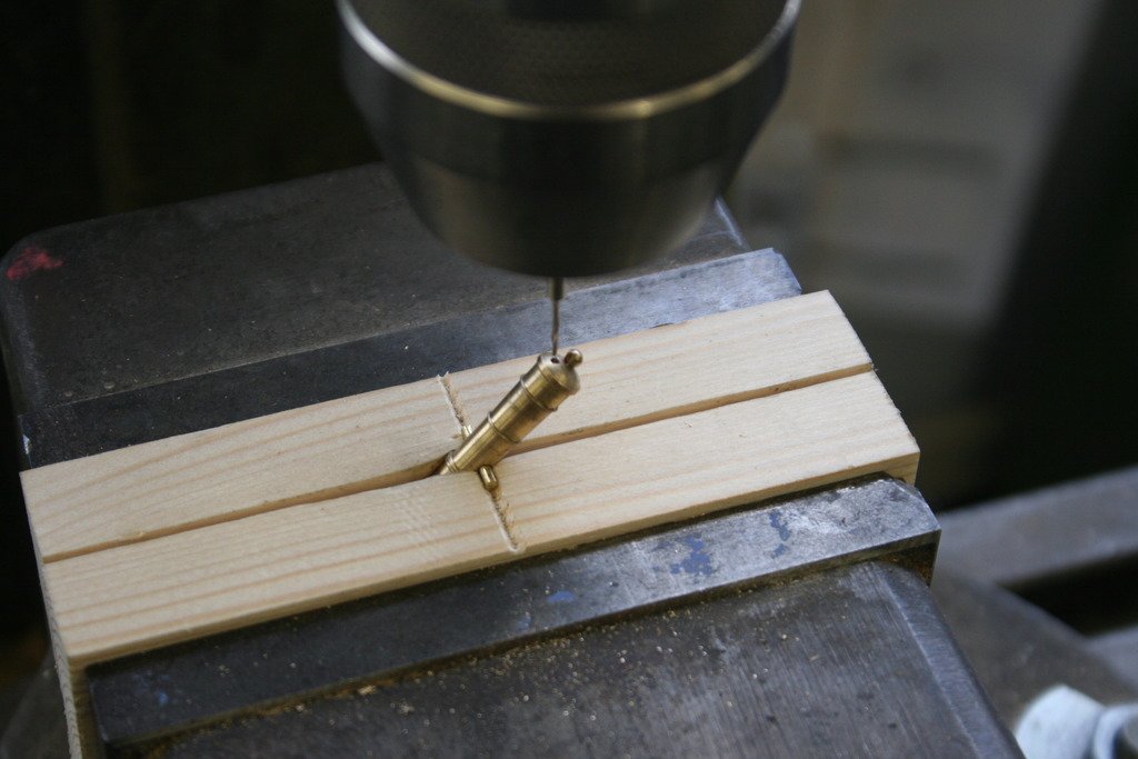
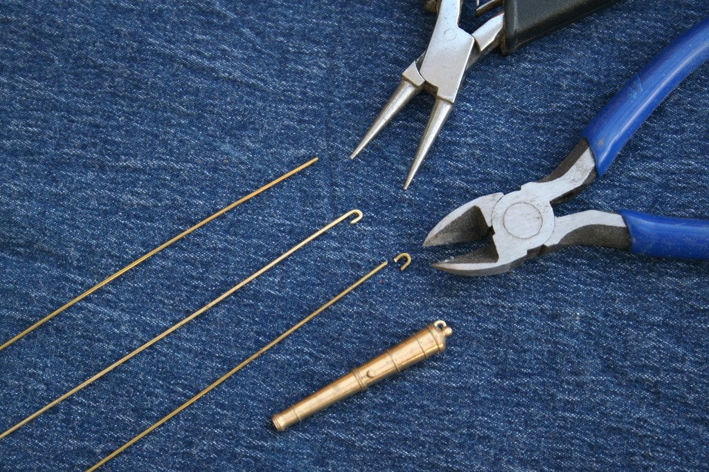
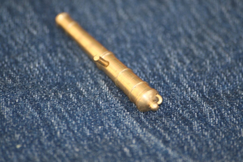
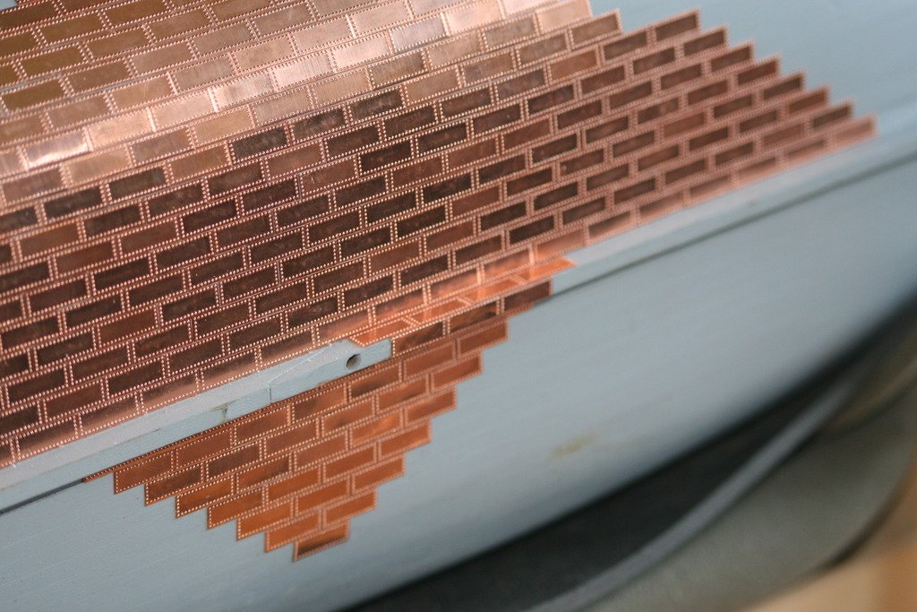
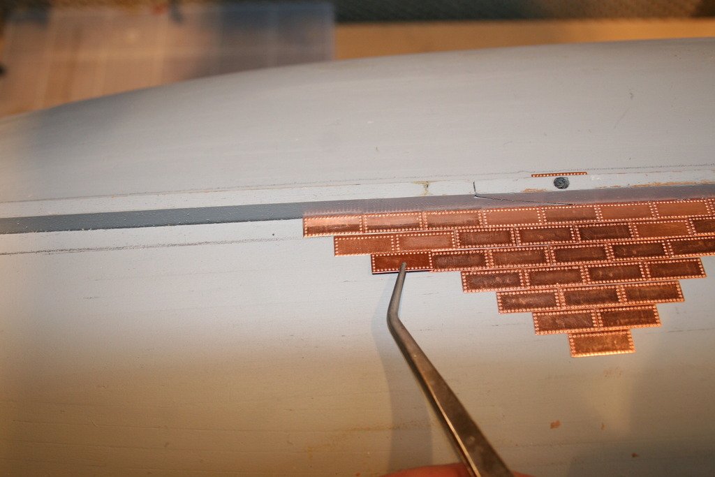
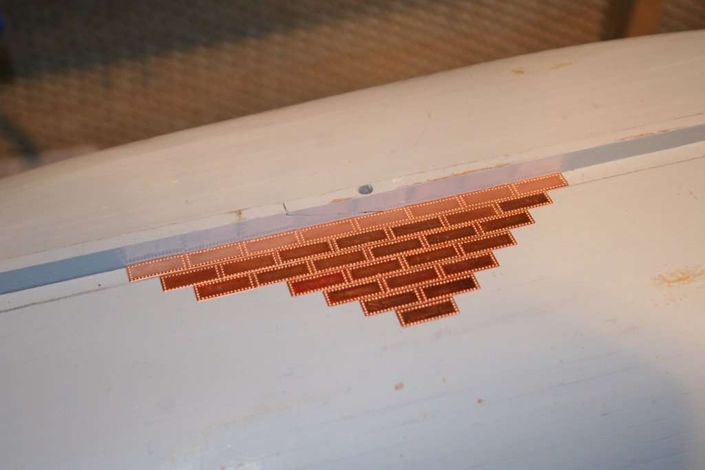
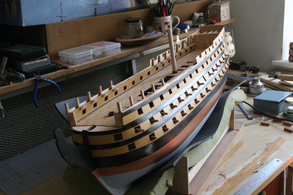
Hi, Work with the copper plates progresses steadily, although slowly at times. I must be close to having completed about a third of the hull and have got far enough to be able to include the first three of the ‘Victory plates’ on the port side, just under the entry port. They appear slightly different in colour compared with the standard plates and this effect varies depending on the way the light falls on them. I assume this must be due to differences in extraction and refining processes – 18th Century metallurgists did not have access to modern electrolysis techniques. As a break from plating I have been ‘playing’ with the cannons. I wanted add breach rings and after a couple of false starts came up with this method. The cannon was clamped in a machine vice on a milling machine that had been set up for drilling. Softwood jaws prevented any damage to the cannons, they rested on the pivot and were set at an angle of 45 degrees measured on the bottom edge. Two 1 mm holes were then drilled. For the rings themselves I decided to ‘roll my own’ from 1 mm dia. Brass rod. This was done with a pair of fine round nosed pliers. The loop was cut with side cutters and after a little tweeking the loop was pushed into place and fixed in place with CA glue. Assembling the gun carriages next! Cheers for now. Graham.
-
Firstly let me say that I am no expert and no doubt there are far more knowledgeable members out there .... but here's my 'two peneth' I've used this composite material to join R/C aircraft cowls and wing halves and to scratch build wheel spats for a 1930's style R/C model. Be warned - it's messy, smelly, you need to work quite quickly - but it's a lot of fun and very rewarding once you get the hang of it. Health and safety - you need to work in a well ventilated area and wear rubber gloves. I prefer the surgical type. Not sure how much detail you want here, so ..... Glass Reinforced Plastic (GRP) combines the tensile strength of glass strands with the properties of a plastic, usually polyester resin although epoxy is also sometimes used. The glass matting comes in three basic forms of various weights and sizes: Chopped strand - good for moulding compound curves like hulls, fuselages, cowls etc. Woven - including a woven ribbon good for joining wing halves, GRP canoe halves, cowling halves etc., and Finishing tissue - a light weight cloth and probably the most suitable for your intended purpose. The resin needs a few drops of a catalyst to make it harden. As far as colouring goes once it has cured you can spray it with primer and then a colour of your choice. You can alternatively add coloured pigments to the resin so that it is 'self coloured'. These are not too expensive, and you only need a couple of drops, but to be honest spray cans, or an airbrush, are probably a more economic option when you're getting started. You would also need plenty of acetone for cleaning up equipment. Your hull would need a coat of resin, a layer of finishing tissue and a further coat or two of resin, probably brushed on. If you really get into this stuff you will learn how to 'stipple ' resin on or, on bigger jobs, to use a roller (not to be confused with decorating rollers!) Once the resin has fully hardened you will need to rub it back with progressively finer grades of 'wet and dry' and / or rubbing compound, being very careful not to rub down to the glass layer, to get a good surface finish. The biggest issue with suppliers is buying small quantities suitable for modelling. Some of the materials have a limited shelf life. It's not particularly expensive, although it's all relative I suppose. Some model shops stock it, although changes to what can be sent through the post has impacted on the mail order route to some extent. If you want to 'have a play' you can buy a car body repair Glass Fibre kit from National retail chains such as Halfords (I checked - there are half a dozen in Belfast!) for about £15. It has the resin, hardener and chopped strand matting in it. There are some really good 'how to' video clips out there on You-tube that will help you too. Now the hard bit...... it's your build, and you are the Captain so the decisions are all yours, but if it was down to me I wouldn't use this as a finish on this beautiful boat. I'm sure that there are better methods to achieve a quality finish on your hull. At the very least have a practice go or two on something else first before deciding. Good luck! Graham.
-
Hi Steve, How are you thinking of using the fibre glass - as a layer on the outside of the hull? or as a lining inside the hull?
-
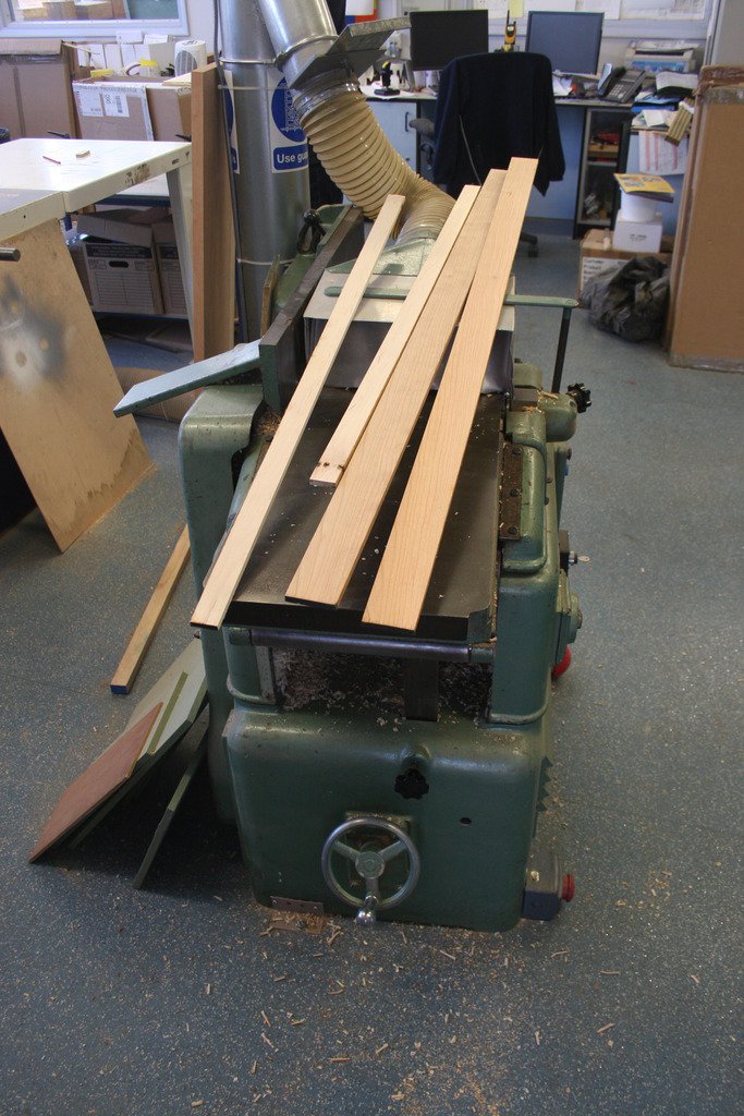
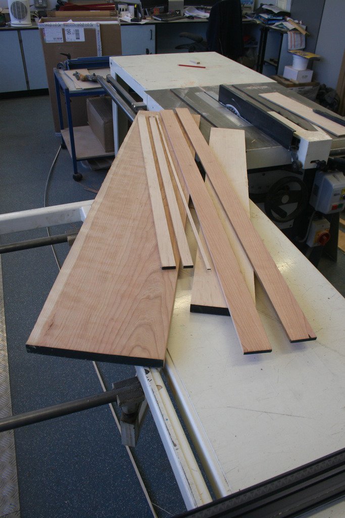
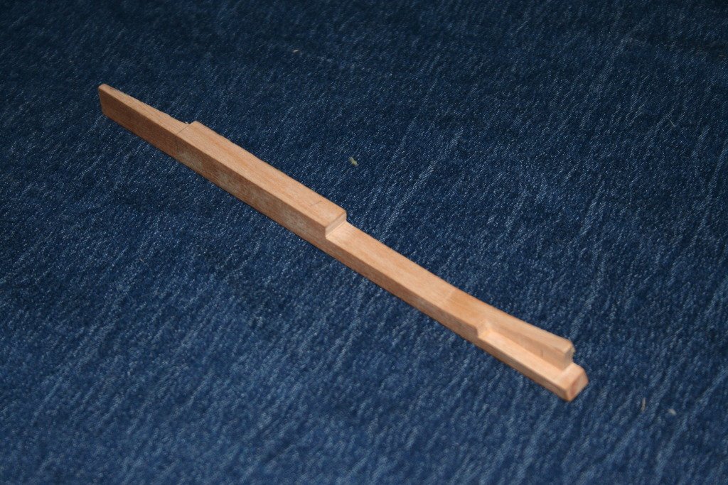
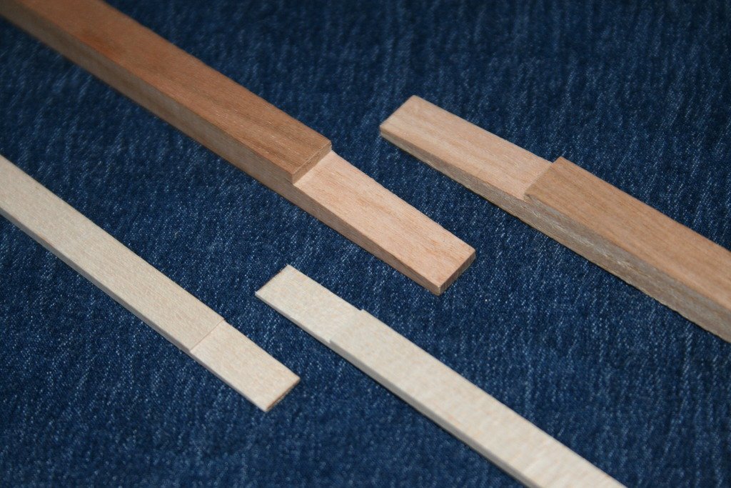
Thanks for the ‘likes’, comments and input. Always welcome and appreciated. Michael (MEDDO) – the equipment is not exactly mine, but having access to it is the next best thing. The planner / thicknesser and I go back 40 years – and I believe it was almost 20 years old when I first used it! I must have fed the equivalent of a small forest through it over that time ….. Christian – I agree that the black and the brown pens that I used on the aft deadwood are too dark. I have found a set of ‘Furniture Touch up scratch repair’ marker pens that contain lighter browns and plan to experiment with these when they arrive next week. In the mean-time the components for the bow structure are ready to be cut out. I’ve been working on the false keel and keel parts this week. All the scarf joints have been marked out and cut. I have also made a temporary filler piece for the space between the fore and aft deadwoods, where the frames will go later, to help with shaping the bottom edges of the keelson components and to aid with the alinement of the various sub-assemblies when they are glued together. I’ll be adding the tapers to the ends later. They are ready for gluing now and once dry I plan to add the treenails to the joints. Showing my inexperience here, but should these be wooden pegs or copper wire? – I’ve seen both methods used ….. Cheers for now, Graham.
- 41 replies
-
- 14
-

-
The jaws were made by injecting heat softened rubberized plastic into a metal female mould sometimes called a 'die'. Once the material has cooled it hardens and the die is opened so the product, in this case the jaw, can be removed. To help get this item out the inner polished surface of the die is first sprayed with a fine mist of 'releasing agent' that helps prevent the liquid plastic from sticking to the metal. It's the remnants of this spray that might have caused the discoloring of the wood.
-
Another thought - your clamp looks pretty new, and the jaws appear to have been injection-moulded. Another possibility could be that there is still some residue of the 'releasing agent' from this manufacturing process on the jaws. I have a feeling that the agent is silicon based, but I could be wrong. Light sanding ought to get rid of it. Good luck!
-
Just another thought - was the hull in direct sunlight while in the clamps? It's surprising how quickly some timbers change colour, lighter or darker, when exposed to daylight.
-
Hi Steve, Really enjoying following this 'retro' build - the finish on the deck is impressive, as is the rate of progress you're making! Keep up the great work. Cheers, Graham
-
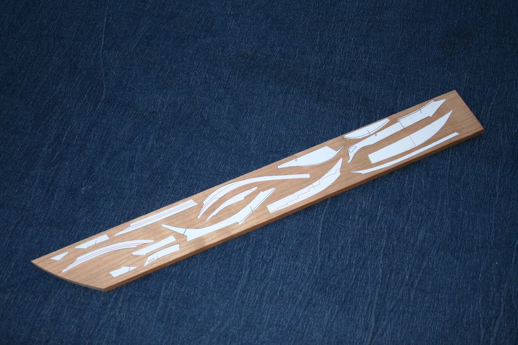
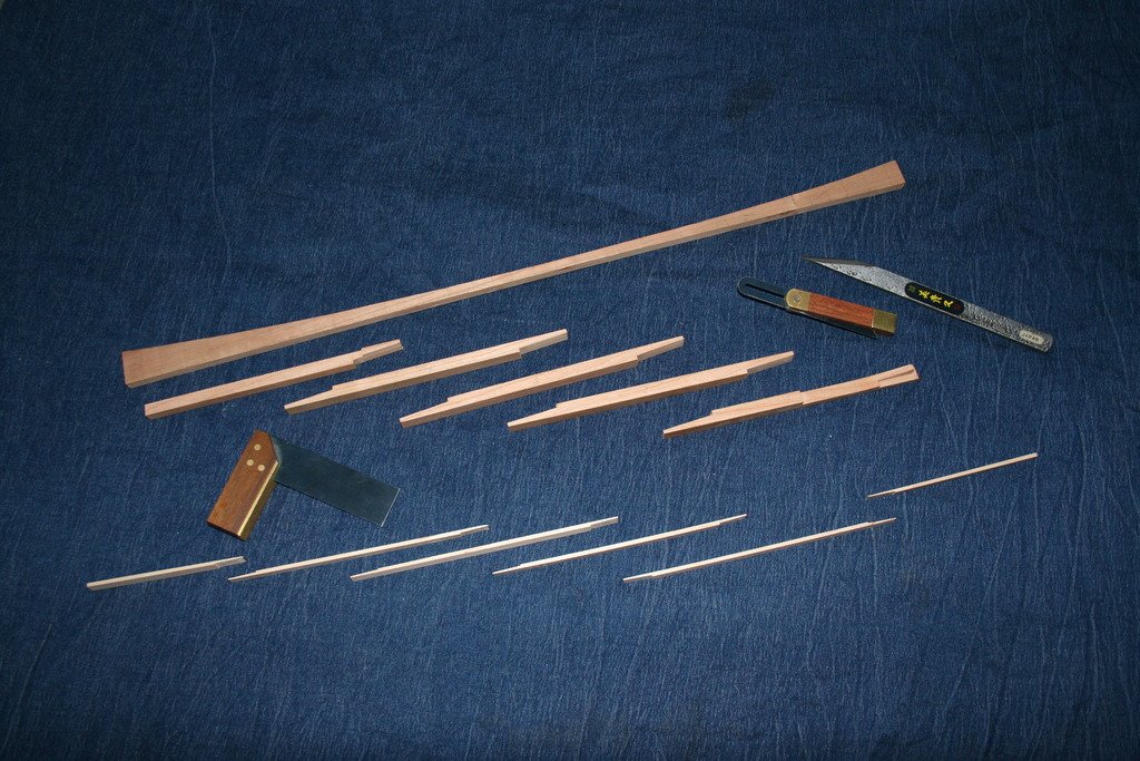
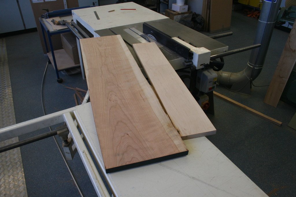
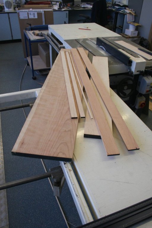
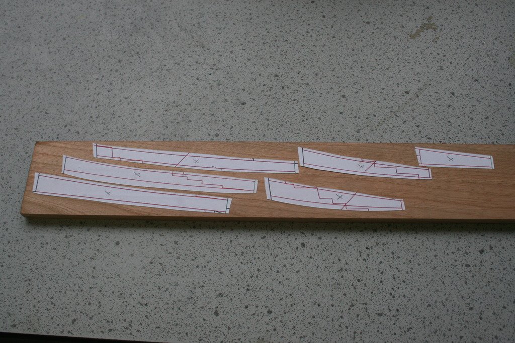
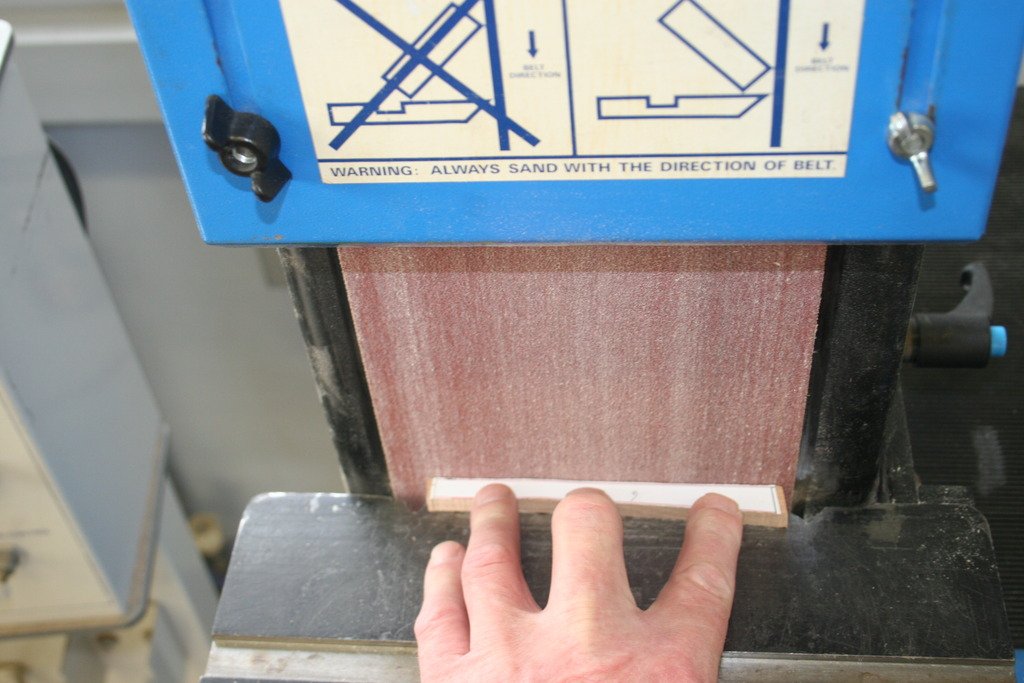
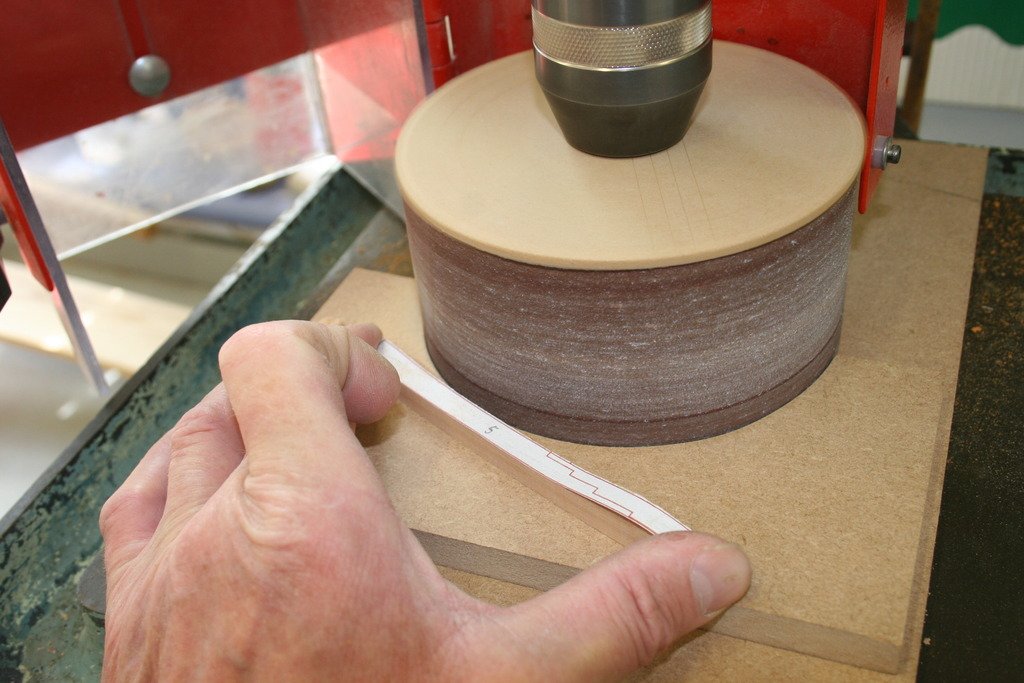
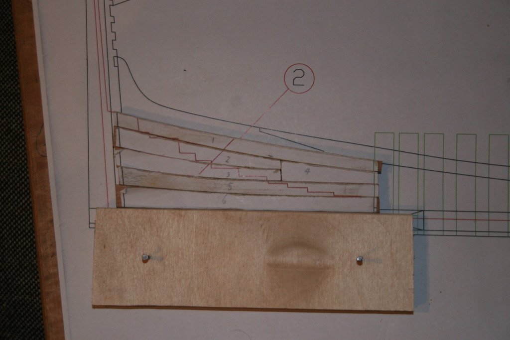
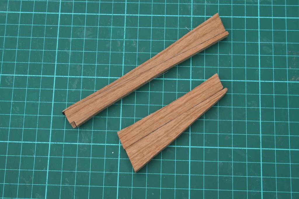
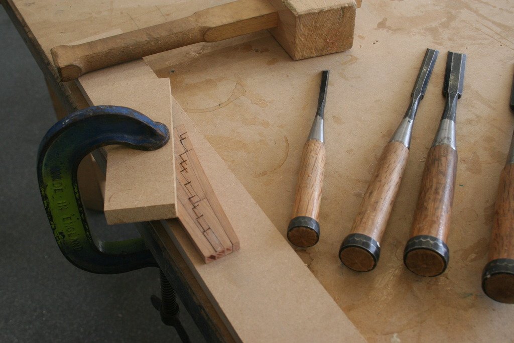
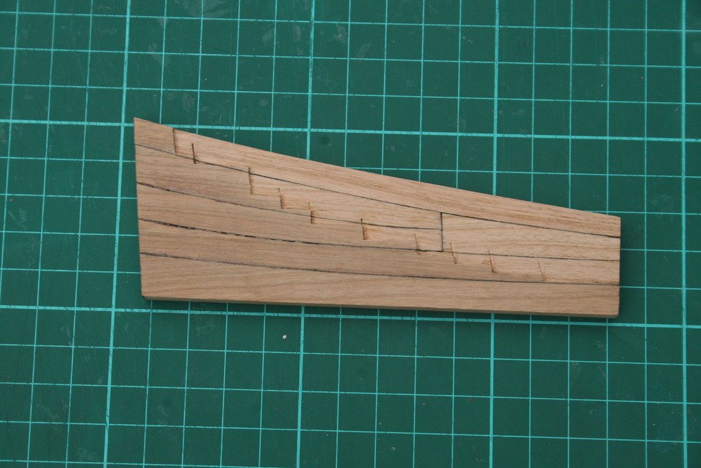
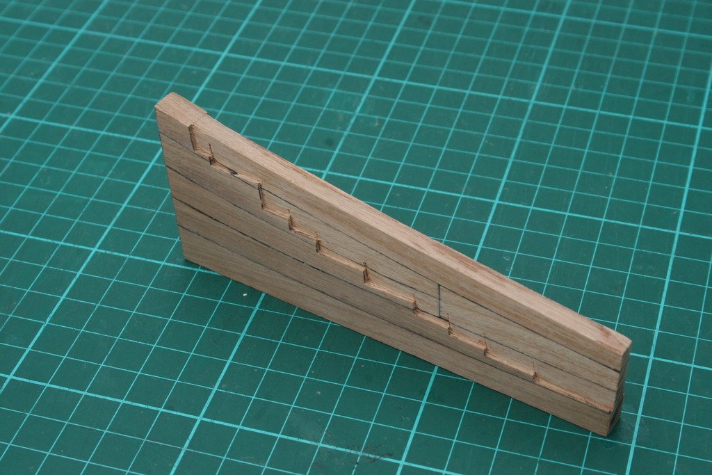
Hi, The first step is often the hardest …. I hope to undertake this challenge of building my first POF ship in order to develop my practical skills and learn new techniques - as well as ending up with a (hopefully) impressive final model. I’ve been preparing for a month or so – downloading the plans for the keel, getting them printed and sourcing the wood. My choice of timber is cherry for the keel and frames, maple for the false keel and other components further down the line and I also have some black walnut in store. The timber as purchased: A strip of each cut off, split and planed down to 8 mm. Ready to start …. The first component I decided to make was the aft deadwood. Patterns cut out and glued onto the cherry with ‘Spray Mount’. I’ve found that this holds the paper in place well enough without leaving any residue on the surface once removed. A couple of times the paper lifted while a piece was being worked but this was spotted and dealt with before errors occurred. After initial cutting out with a band saw edges were refined with a combination of a band facer and drum sander. I have read about, and liked, the technique of enhancing wood joints with permanent marker pens and decided to experiment with black and brown pens on some off-cuts. To say the difference is subtle would be a wild exaggeration! Blowed if I could tell the difference…. The pieces were glued together, cleaned up and the ‘steps’ marked prior to the waste wood being removed with chisels. My first attempt. I’m leaving the final shaping to the sides until much more of the keel has been completed in order to try and get my head around how much wood needs to be removed. I have also been working on making a building board. Before I work on progressing further could someone confirm whether or not this project has been opened to new members again, please? I’m a bit confused by the message saying that it is on the ‘Forum’ front page and the one at the top of the ‘Cross section’ thread saying it’s temporarily closed. In no way is the fact that this project has no big glossy box to smuggle through the back door while the Admiral isn’t looking, thus avoiding the inevitable questions of ‘how much?’ or ‘and where is it going to go when it’s finished’ has absolutely no bearing on my decision to get actively involved ….. honest… Cheers, Graham.

- 41 replies
-
- 17
-
-

-
I'd certainly be interested is seeing the drawing of your plate pressing tool if you can find it, Michael. My own jig is definitely a 'short run' solution. Once I'd proved to myself that the jig worked it went into storage. I'm completing these half dozen now to have them ready to integrate into the upper run of plates just under the entry ports, at least that's the plan. Thanks for ,the 'heads up' on the photo-etch benders, Paul. Never knew such things existed! Must have led a very sheltered life - the photo-etched parts in this kit are my first experience of this type of component ..... Cheers, Graham.
-
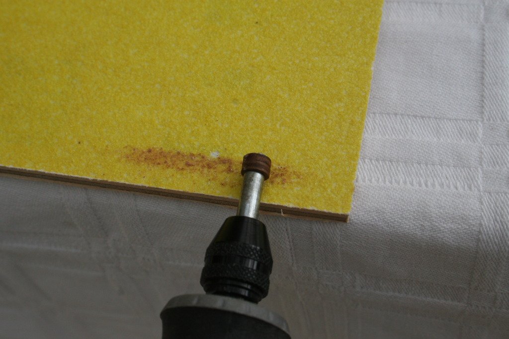
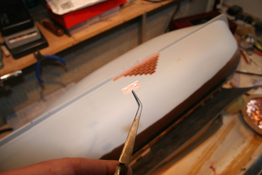
Thanks for your kind comments guys. Robert - your Victory build log is one I often refer to when I need guidance. I wish I’d found your tip on using filler blocks between the bow and stern bulkheads before I’d moved well into the first planking ….. Michael – after a day at the front of a classroom copper plating is a great way to ‘chill’! But you’re right, I do need to break away at times and am working on various jigs to help with adapting and constructing the cannons at the moment. For a really mind numbing task try making the copper plates themselves. I’m currently making half a dozen from copper reclaimed from the scale 1:1 example residing in Portsmouth. Each plate has 40 simulated rivets, each punched individually – I have managed to do two consecutively before having to resist the need to scream or hit the Scotch. …oh, and the Admiral is also adept at interrupting the work flow with numerous little diversionary tasks ….. bless her! Cheers for now, Graham.
-
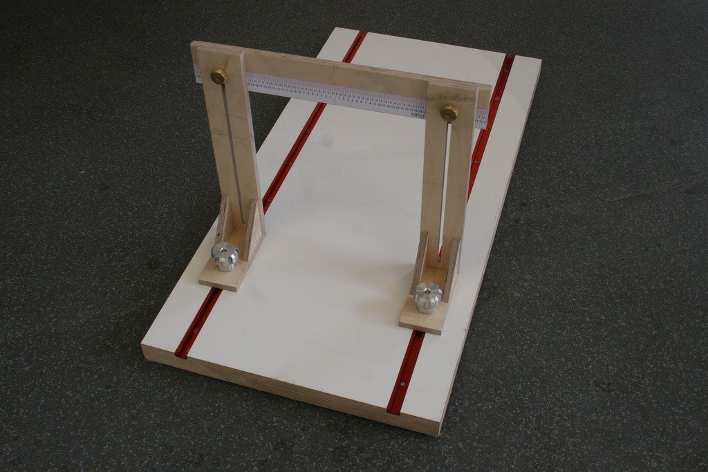
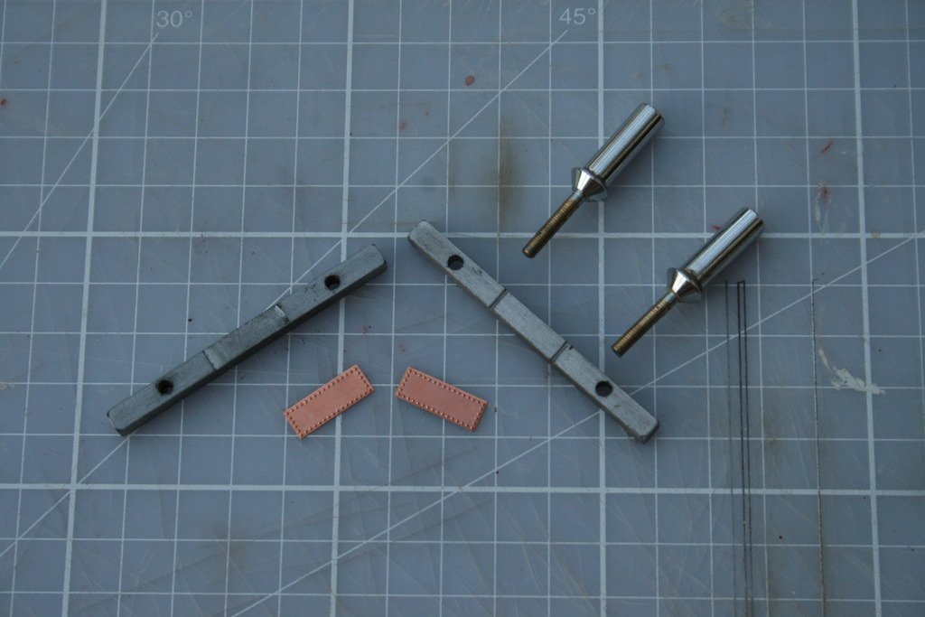
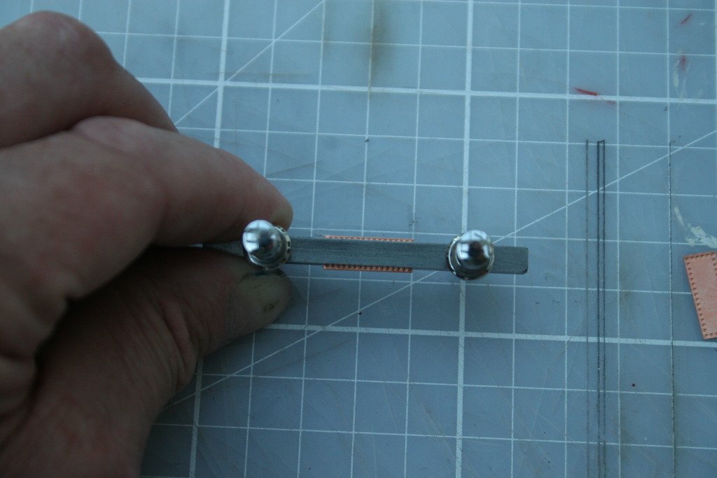
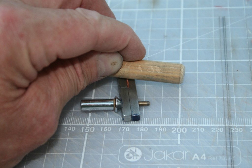
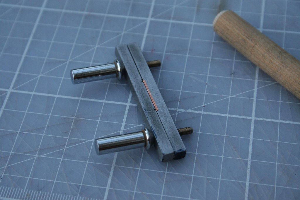
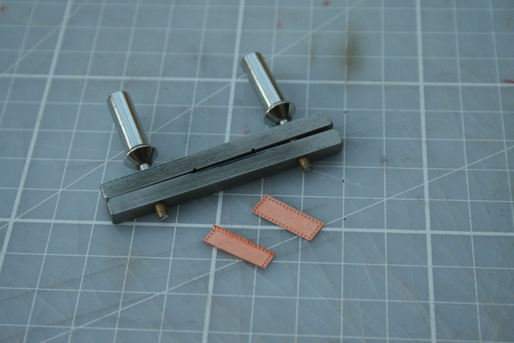
Thanks for dropping by Marc, here is yet another jig! Decision made – I’m going to stick with the approach given in the manual and work up from the keel – thanks Steve for the ‘nudge’ that finally swayed me. After several sessions I have now fitted about 10% of the copper plates. It was always going to be a long haul, but so far it’s been fairly straight forward and surprisingly therapeutic! One aspect that has been giving me food for thought was how to deal with the keel. I wanted to cover the bottom of it with plates folded evenly over the edges. With the keel 5 mm thick and the plates 6 mm wide this means a ‘return’ of 0.5 mm on the side of each plate. Early attempts with flat pliers and then brass soft jaws in a bench vice failed miserably …… With approximately 60 plates needing to be shaped some kind of simple former was going to be required. This is what I came up with: The main body consists of two 60 mm lengths of 5 mm square mild steel bar. The lower part has a shallow recess equal to the length of a copper plate filed into it while the upper bar has two grooves filed in with a ‘three square’ needle file to provide clearance for the raised rivet heads that run across the ends of the plates. I couldn’t find any small diameter socket headed machine screws to apply the clamping pressure in the workshop so resorted to cutting M3 x .5 threads on the pins of a couple of plated brass ‘push buttons’ from old 1970’s telephones that were rattling around at the back of a cupboard – knew they’d come in useful one day ….. Clearance holes in the top bar and suitably threaded holes in the lower bar finish the former. The plate is put in place, but first checked to ensure that the rows of ‘rivets’ on the side are equally spaced from the edges – this sometimes varies considerably. After clamping the protruding edges are pushed by thumb in the right direction and then a piece of softwood dowel is rolled along the edge to complete the bend. ... and the job's a goodun... I hope this will be of some use to other builders. Cheers, Graham.
-
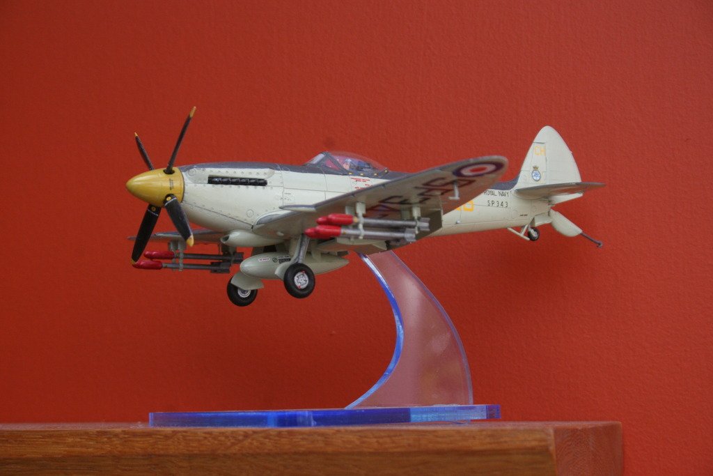
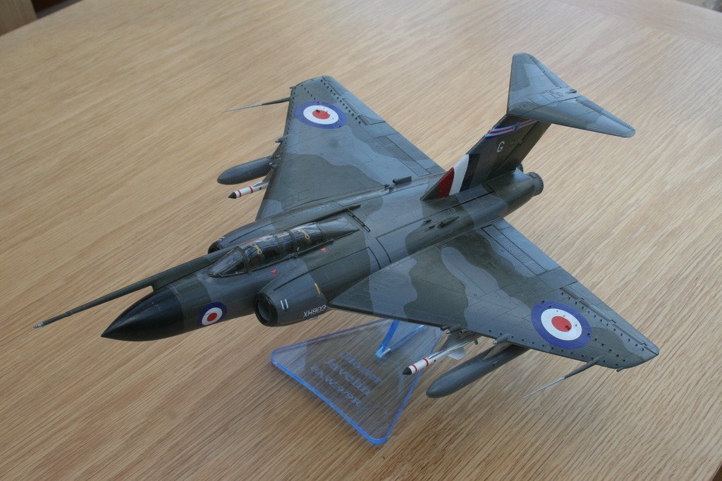
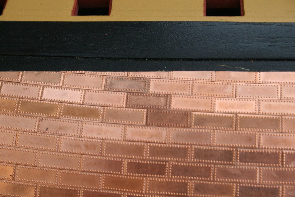
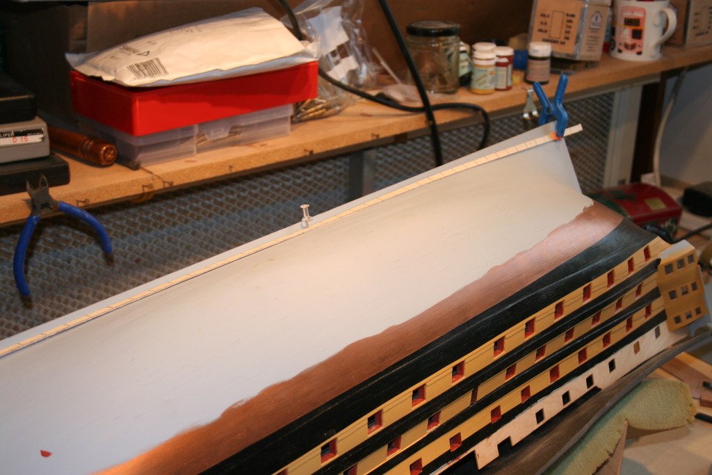
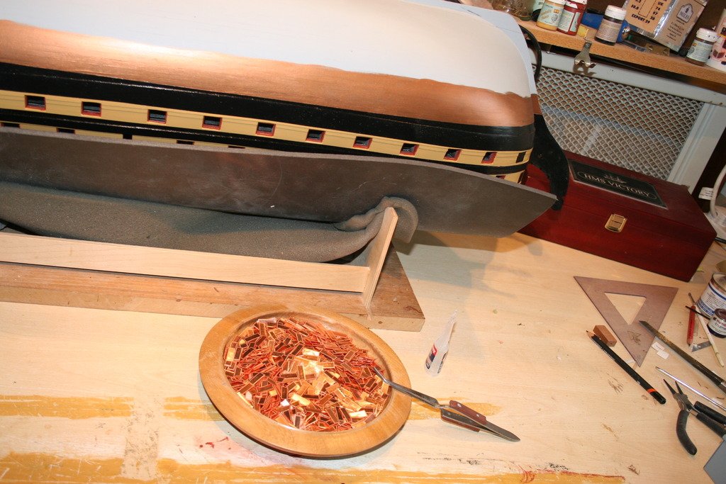
Hi, Thanks once again for the generous comments and ‘likes’ – much appreciated as always. Michael - the Gloucester Javelin has a special significance. My dad worked on their electronic systems when he was in the RAF and I have clear memories of being taken to watch pilots practicing circuits and landings in them - this is probably responsible in no small way for sparking a lifetimes interest in aviation. Meanwhile back in the marine world ,,,,, I need to start this post with an apology! Throughout my career in teaching I have always been an advocate and proponent of the old adages ‘measure twice, cut once’ and ‘never assume …’ In my previous post I referred to the spigots on the dummy cannons being under size. I have since found that this applied only to the 32 pdr cannons. Spigots on the 24 pdr cannons were bang on 2 mm. Consequently the holes in their deck have had to be re-drilled (No. series 44). At least they were under and not oversize. Progress with my Victory has been a bit slow over the last couple of weeks. I have just returned to work after an absence of over a year, all be it now on a part time basis, and to be frank I have returned home most days well and truly knackered. It’s been a long and at times difficult journey but the end is at last in sight. Modelling activity recently has inevitably been a case of quietly browsing this site (always time well spent). I have now started to add the copper plates to the hull. A strip of micro-ply as wide as the plates and marked with divisions equal to their length was pinned to the hull to help gauge the fall of the ‘part’ plates at the ends of the initial runs and to mark the width of the first line. The plates are being attached with a couple of drops of c.a. glue applied before being pressed into place. I am still thinking about whether to follow the method described in the manual ie. working up from the keel, or to plate some straight runs from the water line down as well. Thirty one plates now in place, so just 2569 to go ….. Onward and upwards! Cheers for now, Graham.
-
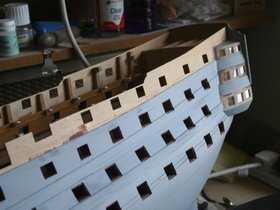
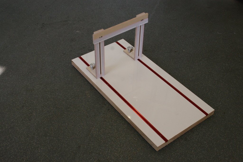
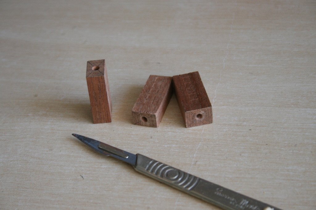
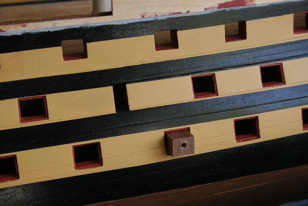
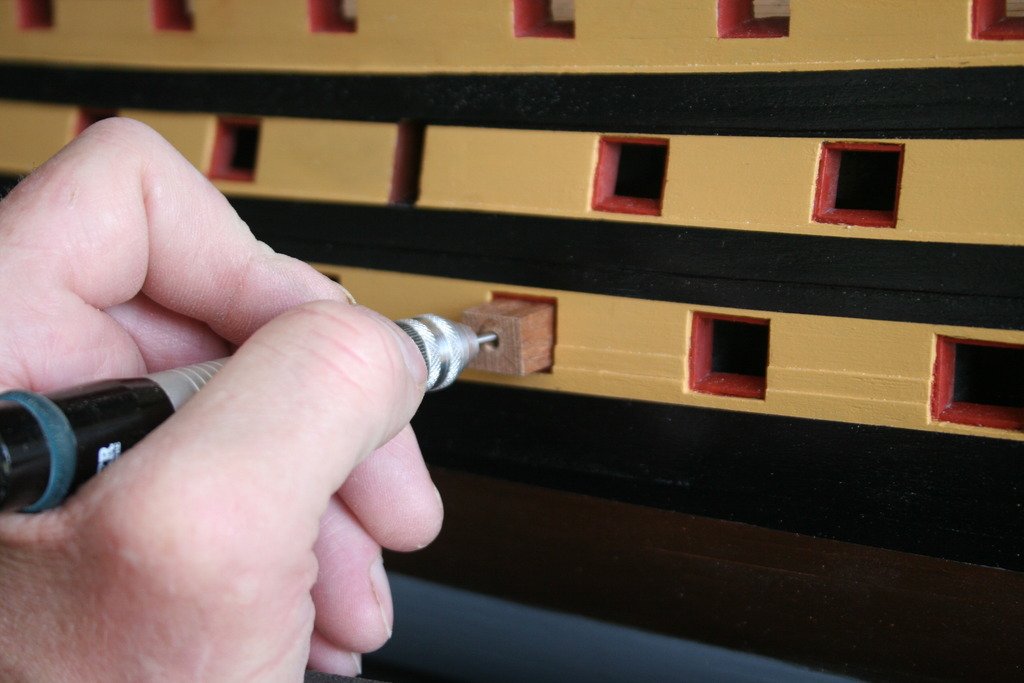
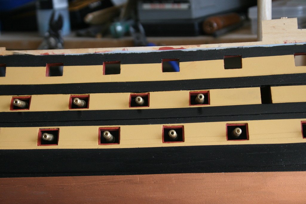
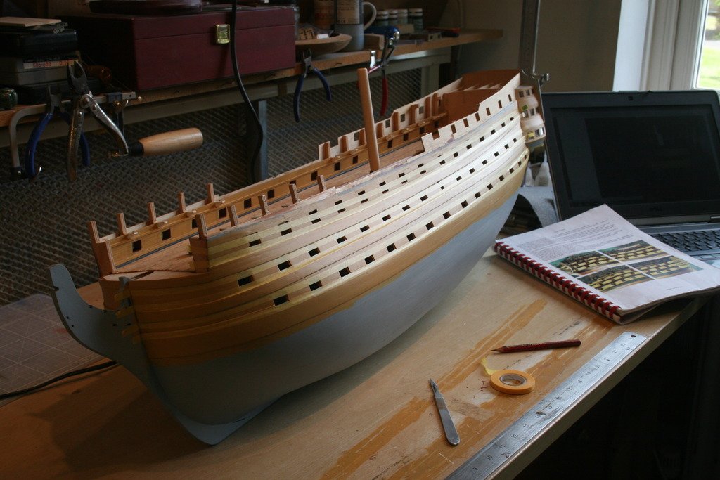
Thanks WackoWolf and mort stoll for the 'likes'. A bit of progress made this week ….. With the aid of a couple of card templates, plan sheet 2, google images and several build logs the location for the dummy gun ports was found and marked onto the hull. One of the most helpful logs was JJacobi’s – thank you! I made a comment on his build log back at the beginning of March about how his build was a few pages further on in the instruction manual compared to mine only to discover that he was still in the process of uploading pictures. In truth it transpires that he is way, way ahead! If my Victory gets anywhere close to his in terms of quality I will be well satisfied. The outlines of the ports were incised with a sharp chisel as was the division between the double doors on the middle deck. The ports were then painted. I’ll add the hinges etc. later on. To drill the holes for the spigots of the dummy cannons some simple guides were made. These were produced from some hardwood offcuts trimmed to size to fit the ports and then mounted in a four jaw chuck on a lathe for boring. The manual suggests that the drill to use should be slightly larger than 2 mm. Checking the spigots showed that they were well under this size coming out at about dia. 1.77 mm. Trial holes drilled in a spare piece of ply from the kit resulted in my selection of a Number 49 drill bit (1.85 mm). Although they still need painting I couldn’t resist pushing them temporarily into place. I’ll be spraying the cannons at the same time as the upper gun deck barrels but first I have plans to modify these. More details will follow once I’ve worked out how to achieve the results I am hoping for. As for progress with my other project - I finally found a couple of UK based suppliers of T Track. Neither have them I stock at present but at least they have been ordered. I now have the base board ready and waiting for them, the parts for the gantry prepared and the set of 1:48 scales printed. About time to start shaping some wood, I think, and another build log to begin ….. With the Victory build the next challenge is the copper plating – lots and lots of copper plating ….! Cheers for now, Graham
-
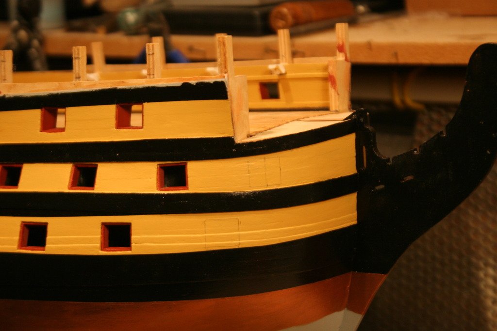
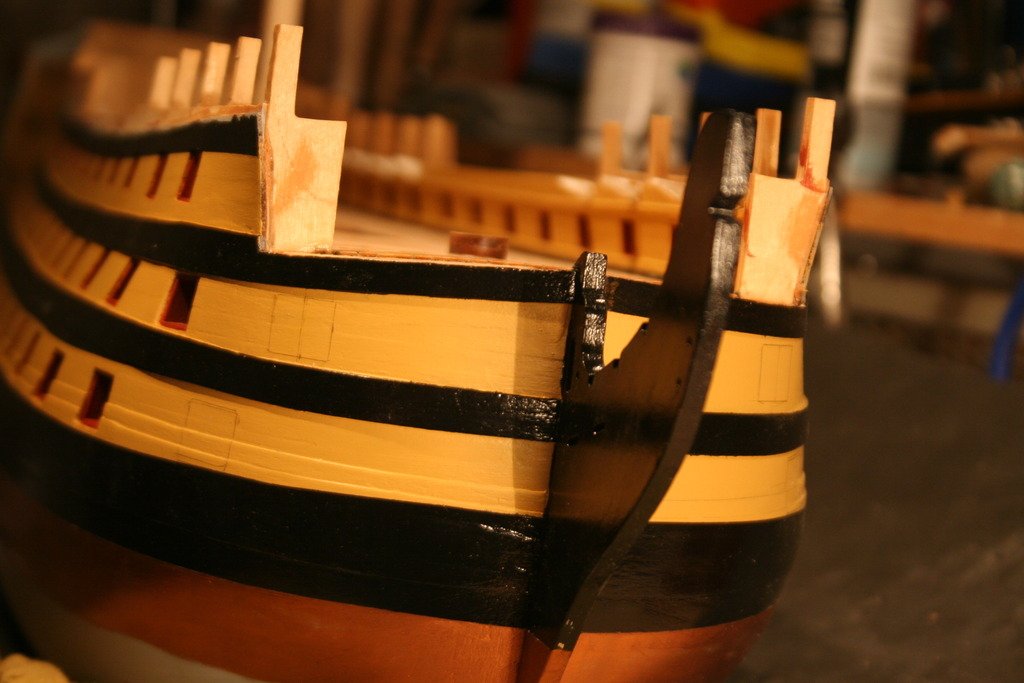
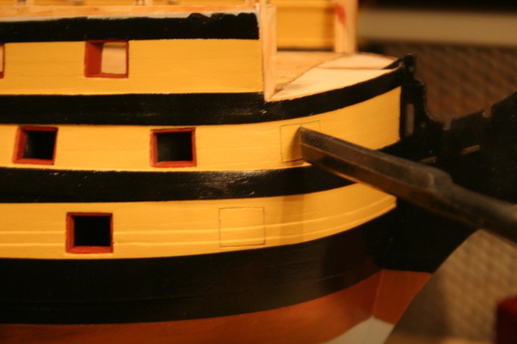
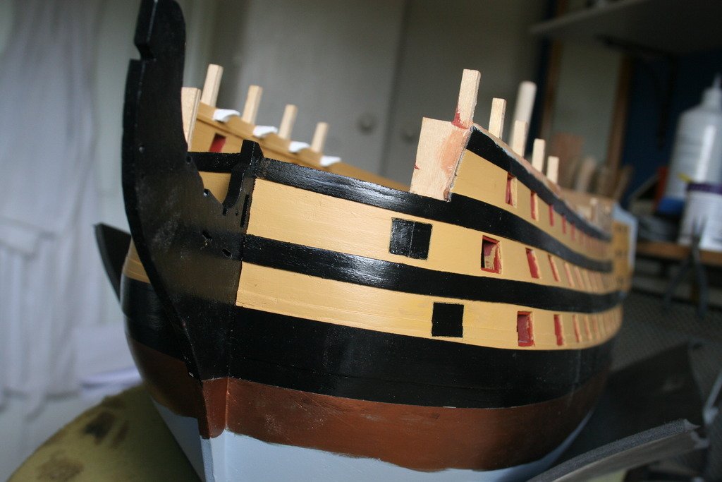
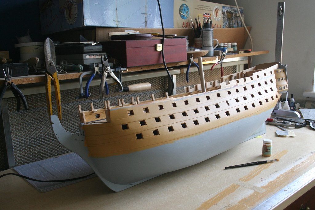
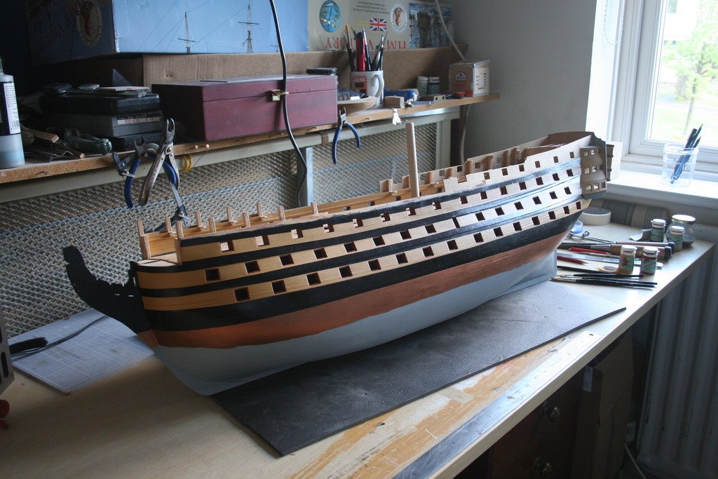
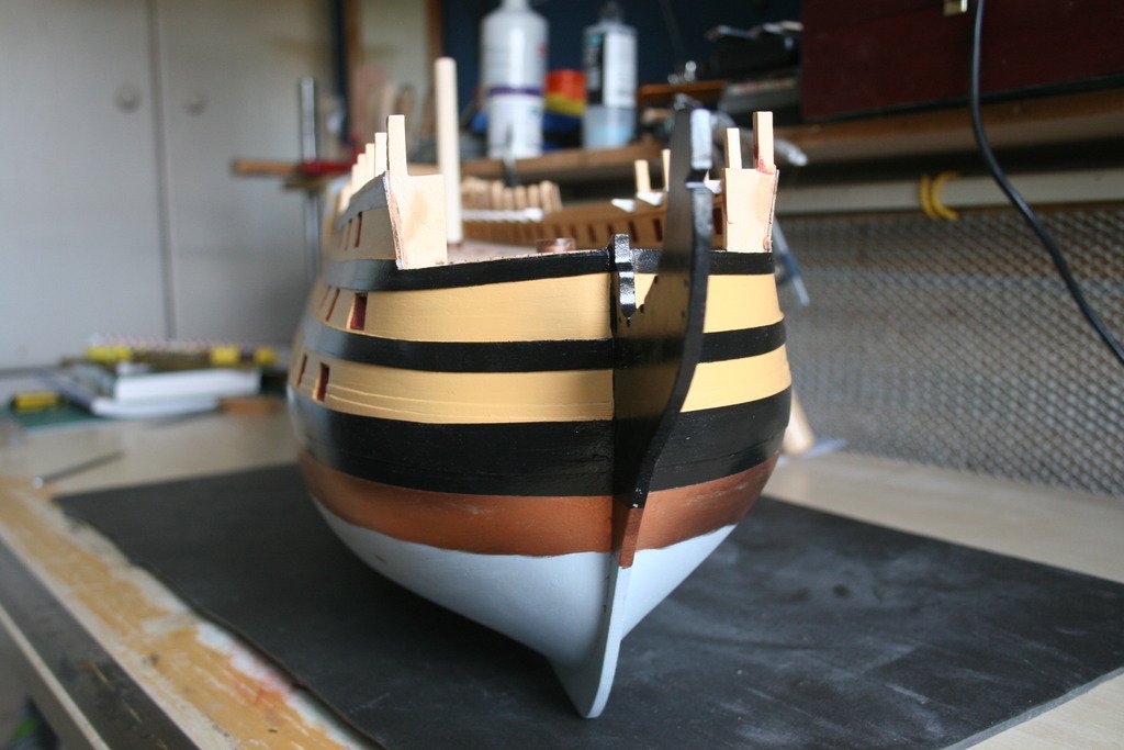
Hi, It’s been a little while since my last post – life can get a bit complicated at times! Thanks’ for all the ‘likes’, they are much appreciated and a source of motivation when tackling those more challenging tasks. Before starting to apply the paint I did a bit of improvising with the tools to hand and marked on the waterline. Two coats of yellow ocher where brushed on and once dry, after several attempts to get the lines right, the edges of the black strips were masked off using Tamiya’s fine masking tape. Two coats of black paint later the tape was removed and the gun port linings were then neatened up with red ocher and a very fine brush. My concerns that I might lose the definition of the different plank patterns on the wales proved unfounded. Finally I masked along the waterline and applied some copper paint. Next task is to mark out the additional gun ports on the bow and come up with some kind of drilling guide for the dummy guns on the lower and middle decks. Cheers, Graham.
-
Yes - it was the 'stage 4' drawing that made me think that there had been an error in the top side view. With reference to the sanding - glue the bulkhead in place, adjusting the central slot length might reduce the discrepancy at the top a little, and then once the stern extensions have been fitted wrap glass paper around a sanding block to keep it flat and carefully rub all the top edges until they are all the same height. Hope this helps:
-
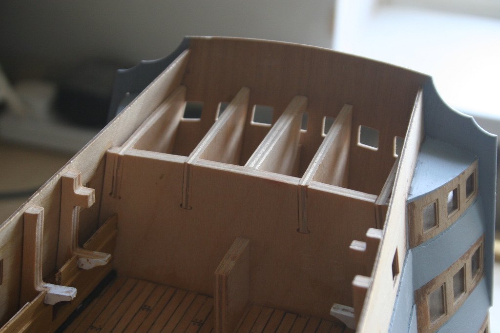
Hi Michael, Great work on the bow bulkhead fillers! Yes, the top of the last bulkhead does need to be flush with the middle support as there is a deck that sits on top. I would wait, however, until you have also fitted the stern extension pieces 105 and 106 as the whole lot can then be sorted out, ie. sanded down level, together. Just one point to watch out for in the future - the piece that sits on top of this area is shown as part 443 on plan sheet 1. I can't find this in the parts manual which skips from part 432 to 445. I think, from having a very quick look, that '443' is actually 447, the poop deck.. I'll check this again later. If any other builders have come across this they might be able to advise us. Cheers, Graham.
-
Hi Steve, Among her many talents the Boss (Admiral) is an accomplished stained glass worker. In my role of 'Chief Sharpener of tools' I've had to renew the cutting edge of a similar knife ....... Cheers, Graham
- 291 replies
-
- 2
-
-
- bounty
- billing boats
- (and 1 more)
-
Amazing work, Steve. Your rate of progress is also impressive. Like your use of the lead putty knife - very appropriate for constructing galley windows! Cheers, Graham
- 291 replies
-
- 3
-
-
- bounty
- billing boats
- (and 1 more)
-
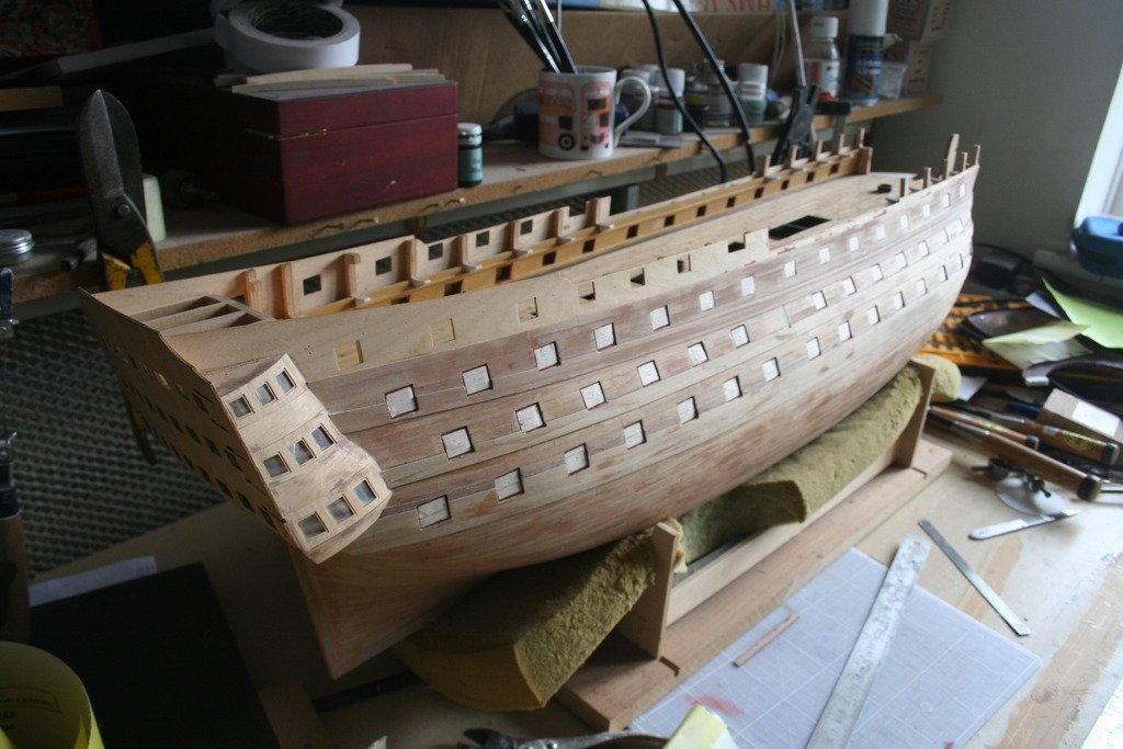
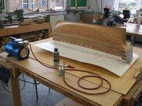
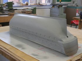
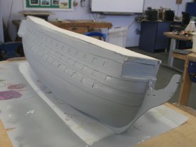
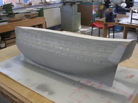
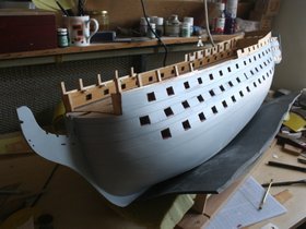
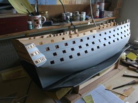
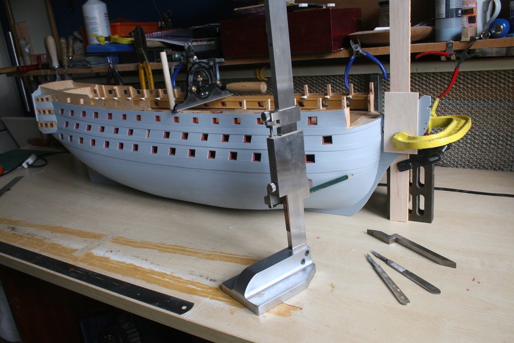
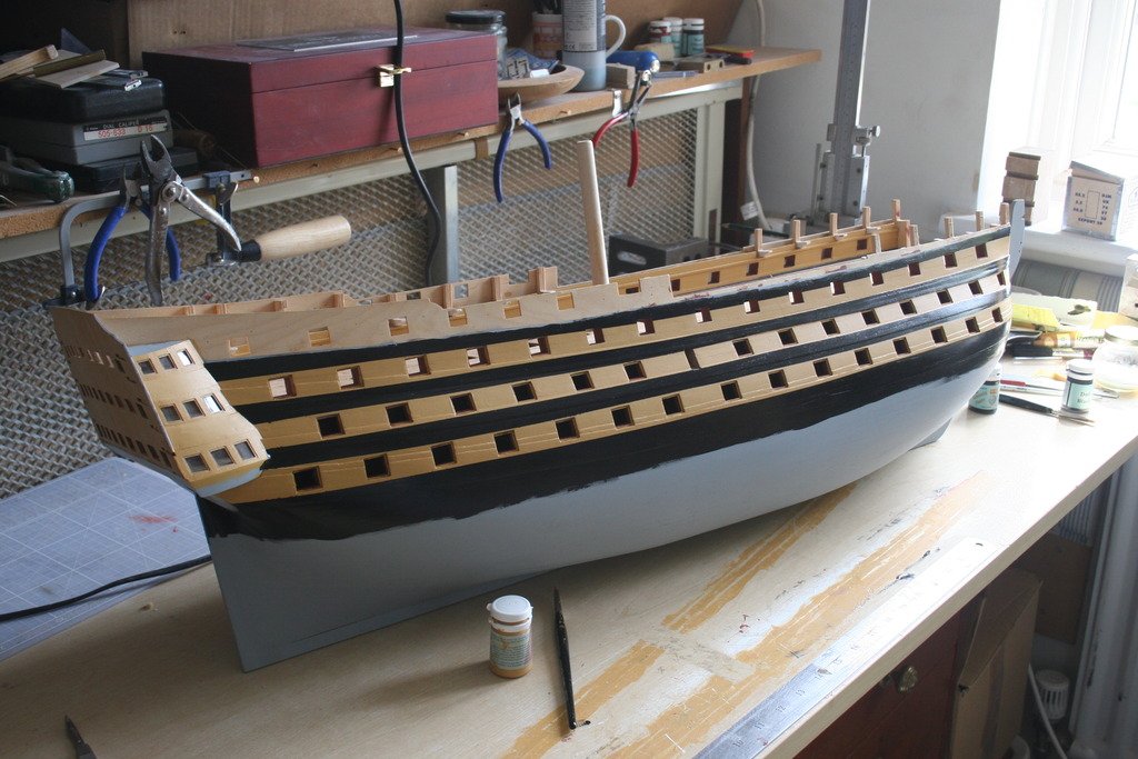
Hi, With the gun ports now lined the construction manual recommends painting the hull before undertaking the copper plating and decking out the upper gun deck. With such a large area to deal with I had already made the decision that the way forward was to use an airbrush. Problem – never used one! Always up for a challenge, and able to access the equipment, the sensible decision was to have a go on something else first. My model ‘stash’ included two plastic kits - a Seafire bought primarily as a research source for detailing an electric motor powered R/C version I was building, and a Gloster Javelin given to me by my department colleagues to keep me occupied while on extended sick leave. Haven’t built a plastic kit literally for decades and they have certainly come on in terms of complexity! These photos show the results. Both kits had the feature of two colours meeting in a similar way to the black and yellow ocher strips on the Victory. To cut a long story short using an airbrush, like any new tool, requires plenty of practice. I got the hang of applying paint to broad areas but struggled a bit with achieving crisp lines where two colours meet. I resorted to having to touch these up with a paint brush. Rather than risk this on the hull I decided to modify my plans and use the airbrush to apply primer to provide a good base surface and then to brush on the final colours. The first step was to blank off the open gun ports to stop the spray going into the hull. This was done with pieces of soft balsa sheet cut to size and pressed into place. The heal of a Swan – Morton scalpel handle proved idea for this task. The stern fascia, the quarter gallery windows and the linings of the gun ports with lids were additionally protected with masking film. Finally the top was sealed off with scraps of card and masking tape giving the hull the appearance of a prison hulk rather than a first rate ship of the line …… The Admiral objects to me spraying paint in the house for some reason, although the same rules don’t count apparently when brushing or rolling emulsion, gloss etc. to walls, doors and ceilings ….mmmmm! So, as I had to earlier with the plastic kits, a trip to the school workshops, currently empty of ‘clients’ due to the Easter holidays, was called for. The first coat of primer revealed a few gaps and blemishes that needed a little filler and a light sand before the second and final primer coat was applied. Job done! Next task – applying the colour …. HMS Triton update. Made the journey over to the timber supplier I had found on-line and picked up a piece of cherry and some maple at a good price. A genuine Aladdin’s cave with some fantastic exotic hardwoods and as a bonus they have a range of wood turning blanks. Could have spent hours there! I’ll put details of the company in ‘Wood Discussion’ section. Now to try and source aluminium T track for the building board. Cheers for now, Graham.