Charter33
-
Posts
455 -
Joined
-
Last visited
Content Type
Profiles
Forums
Gallery
Events
Everything posted by Charter33
-
Hi Alan, I thought that hull looked familiar. I'm just putting the final touches to the copper plating on my own identical one, also a present from my Admiral, and also held up for a time by significant health issues. Hope you find a way to solve those problems you've described. I am following your Triton build with interest. I'm focusing on the stern section at the moment and hope to up-date my log in the near future. Cheers, Graham.
-
Just stunning! Congratulations - it's been a real pleasure following your progress. Such incredible detail ...... Graham
- 184 replies
-
- 2
-

-
- ruby & arthur reed
- lifeboat
- (and 1 more)
-
Hi and a big welcome - it's great to see another 'complete' model of Triton get under way. That's a really impressive set up you have there in your workshop. Is that a Caldercraft HMS Victory I see resting on that shelf in the background? I look forward to following your progress. Good luck, Graham
-
A truly stunning build, Don. Craftsmanship of the highest order and impressive attention to detail - congratulations on your inspirational work. I really like your choice of colours for the hull - are they based on a particular full size example? Graham.
- 653 replies
-
- 5
-
-
- trabakul
- marisstella
- (and 1 more)
-
Hi Jim, Your talents seem to have no limit. Love your latest post - my father worked on the electronics in Shackletons when serving in the RAF - he used to refer to them as 10,000 rivets flying in loose formation ...... Cheers, Graham
-
Ropewalk
Charter33 replied to Worldway's topic in Rope Making/Ropewalks's Rope Materials and parts resources
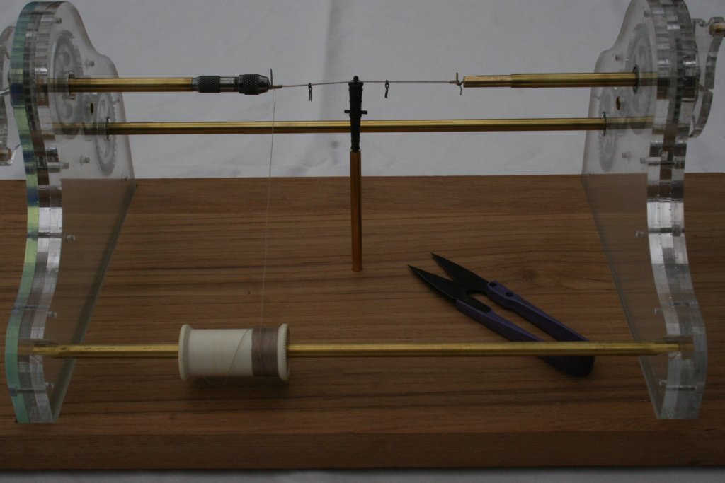
Thank's for starting this thread, Derek, and for re-posting the link to your own design, Steve. I was contemplating having a go at making a rope walk and this has given me the final nudge to get started. I recently put together my own serving machine based on modified Lego gears as little diversion from copper cladding the hull of my Victory build. There's a real sense of achievement when it all comes together and works ...... Cheers, Graham. -
Superb work Jim. I love the detail and the 'atmosphere' you instill in your work. I particularly appreciate your depiction of Bucklers Hard - one of my most favorite places in the New Forest. Thank's for sharing them. Graham.
-
Hi and a big welcome! I was not familiar with your choice for a first build so I've just looked it up on Google. I'm sure you will find that it will be a rewarding and satisfying project, especially with your previous modelling experience. I was in a similar position to you and convinced myself that I'd taken on a project far beyond my abilities. I then learned two essential lessons: firstly you never know what you can achieve unless you have a go, and secondly that this site is in a class of it's own when it comes to the support and guidance available. Best advice is to start your own build log - and if a challenge arises just ask. There are so many talented builders here keen to help others succeed. Good luck! Graham.
-
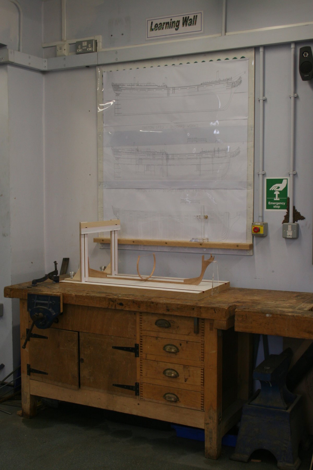
Hi, The workshop is a school workshop. On a typical day I can share it with approximately a hundred students, in groups of about twenty, ranging in age from 11 - 18. This particular corner I claim as my own, the bench is mine and will be leaving the school with me when I eventually retire, as will my Poolewood wood turning lathe which also graces the room. I will, however, need to sort out a workshop of my own, when that day comes, that will be big enough to accommodate this equipment and all the other bits and pieces that have accumulated over the years! My other project, HMS Victory, is being constructed in the 'spare' bedroom at home, much smaller and 'cosy', to put it politely. I get to work very early to avoid travel congestion - the workshop is quiet, there are no students around, for almost an hour my time is my own ........... is there a better way to start a working day? .... and at the other end of the day, when they've gone home, planning and marking is up to date and any meetings are finished ........... Thanks for the comments and 'likes', the feedback is much appreciated. Cheers, Graham
-
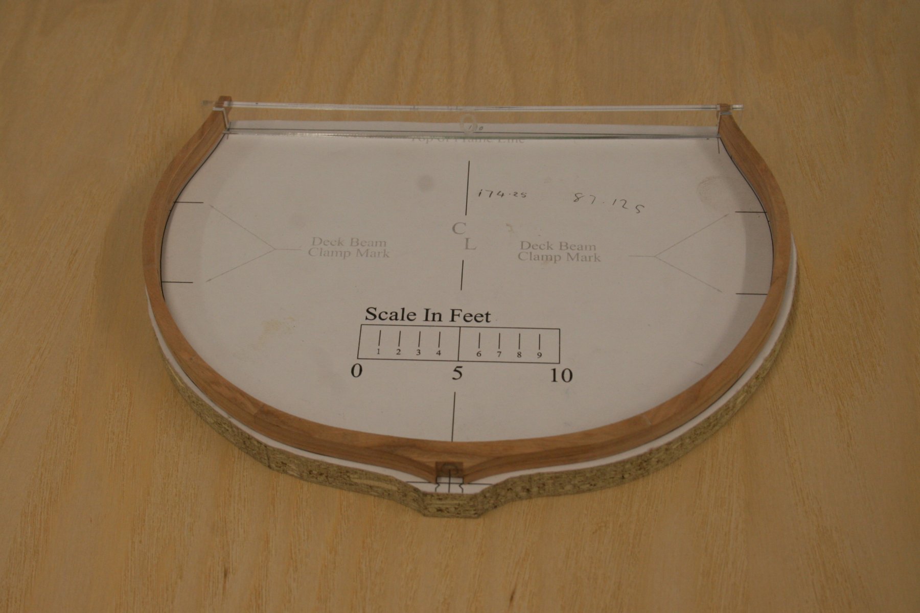
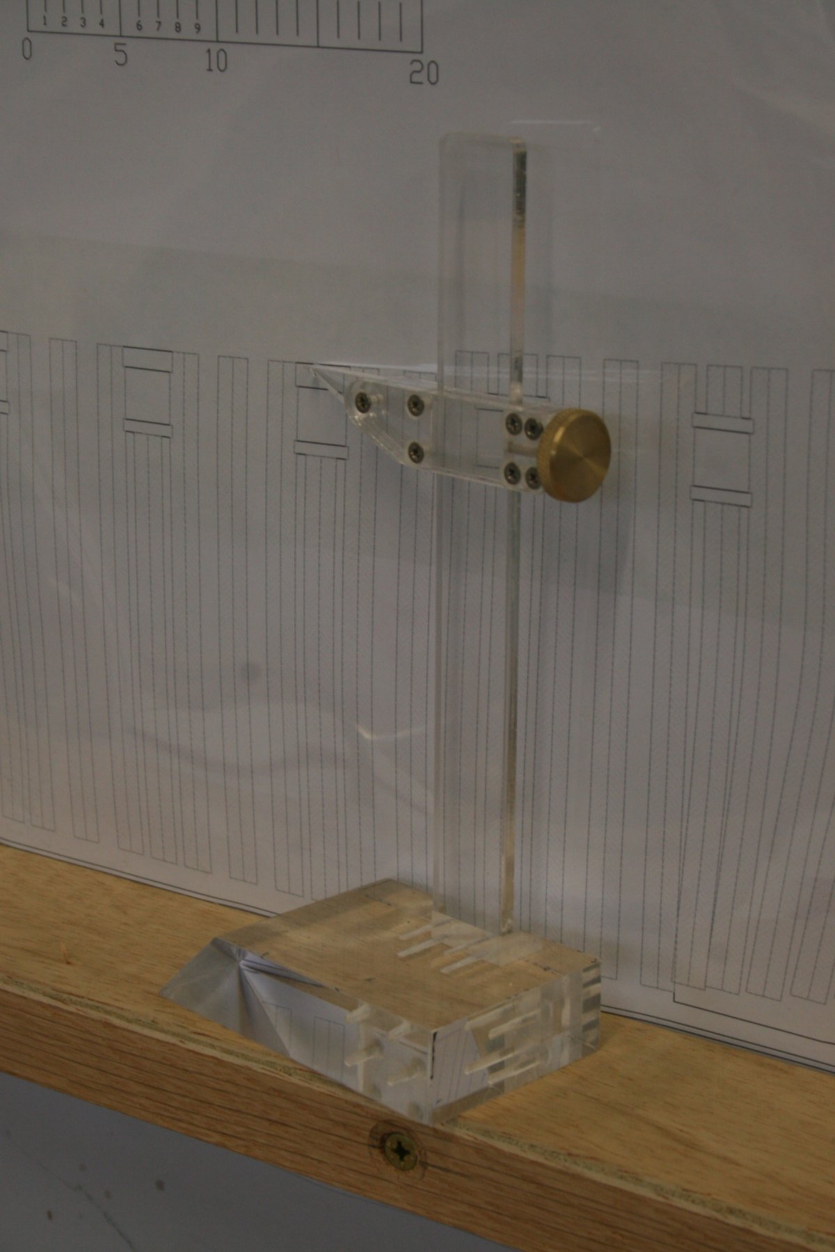
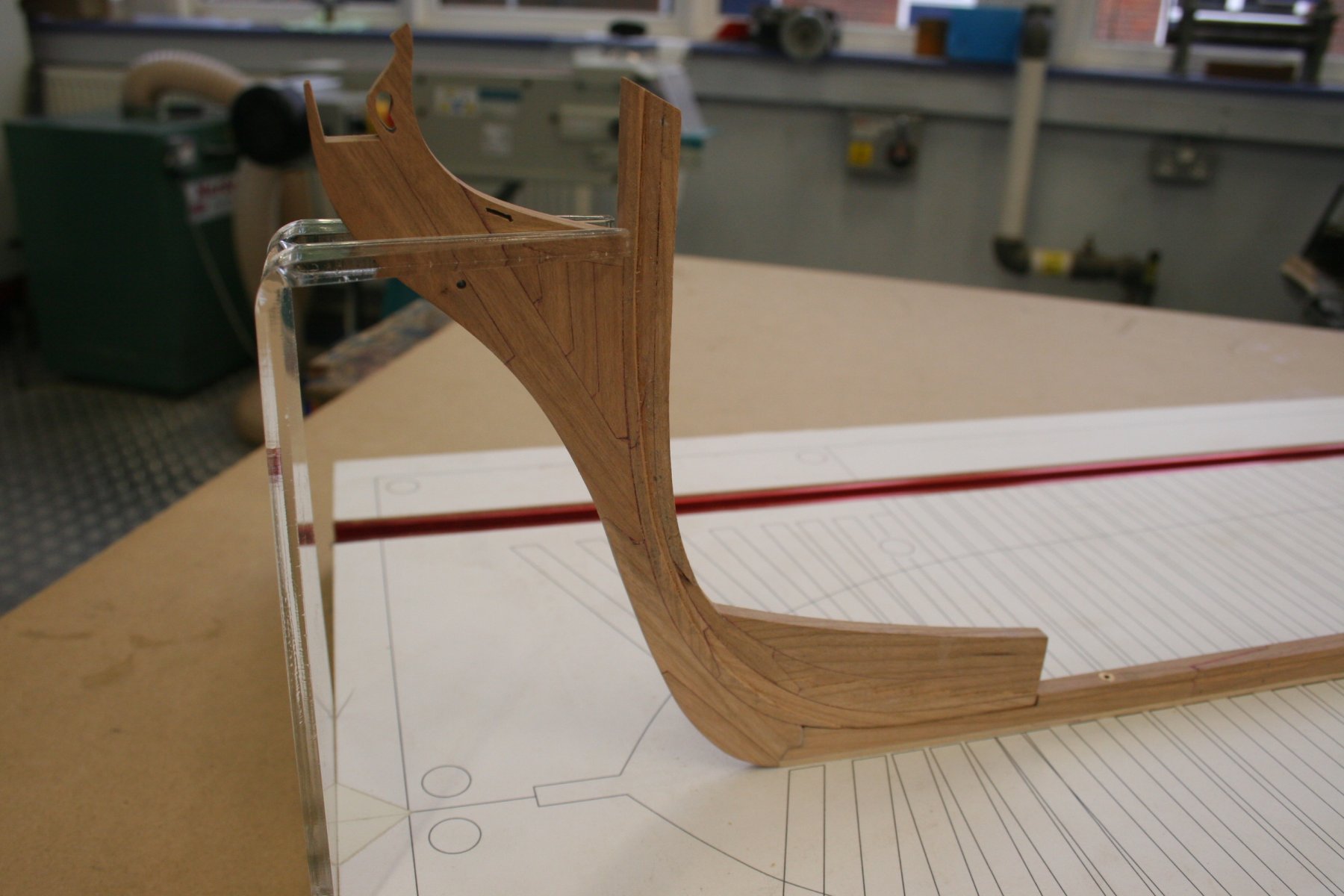
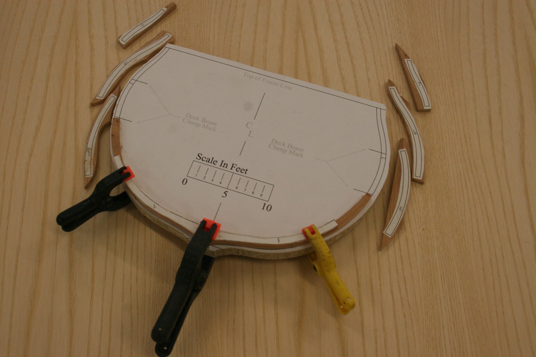
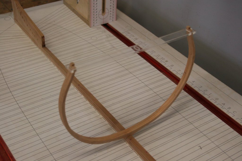
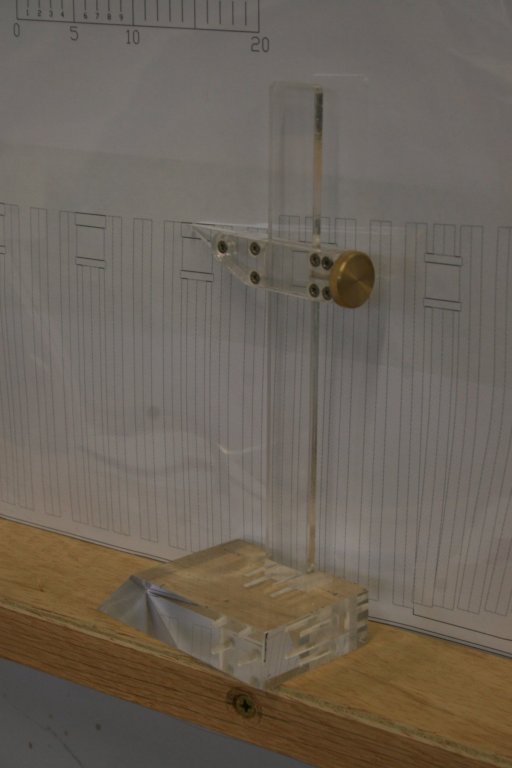
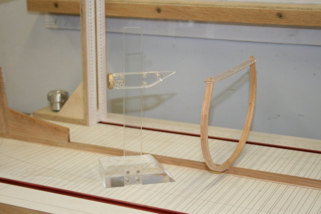
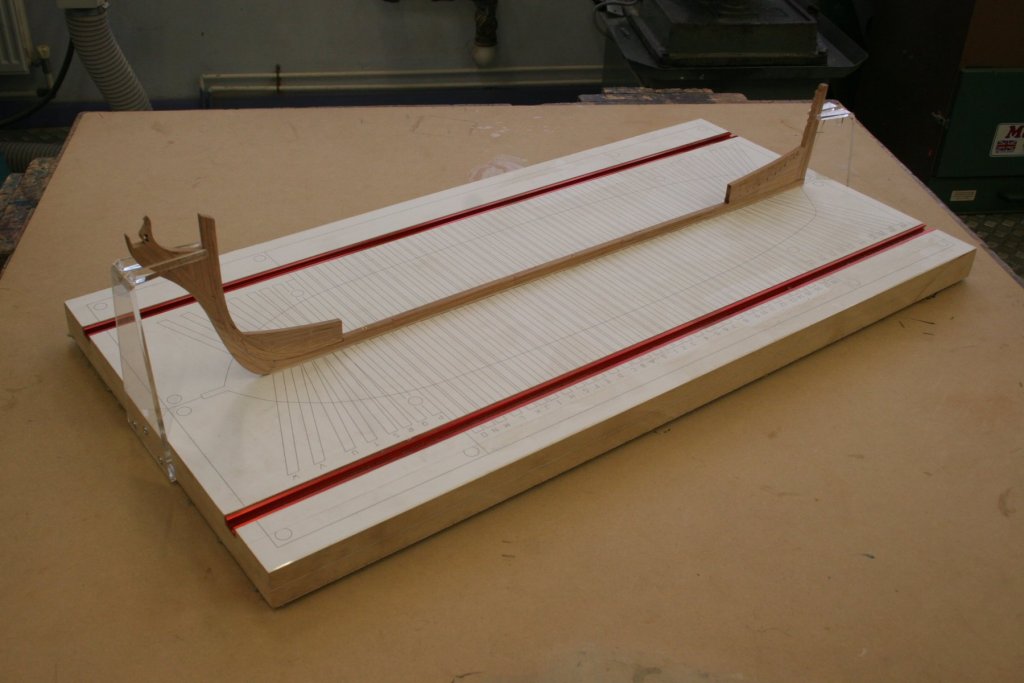
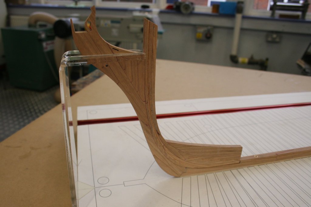
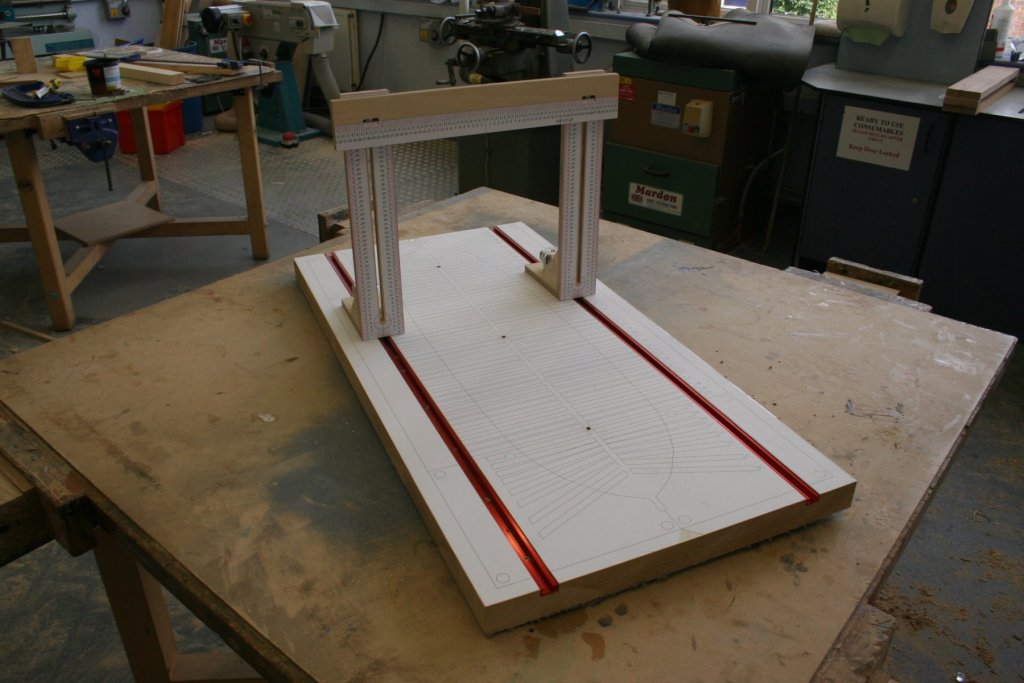
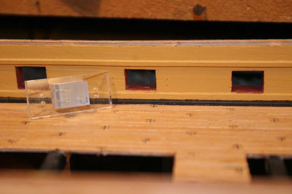
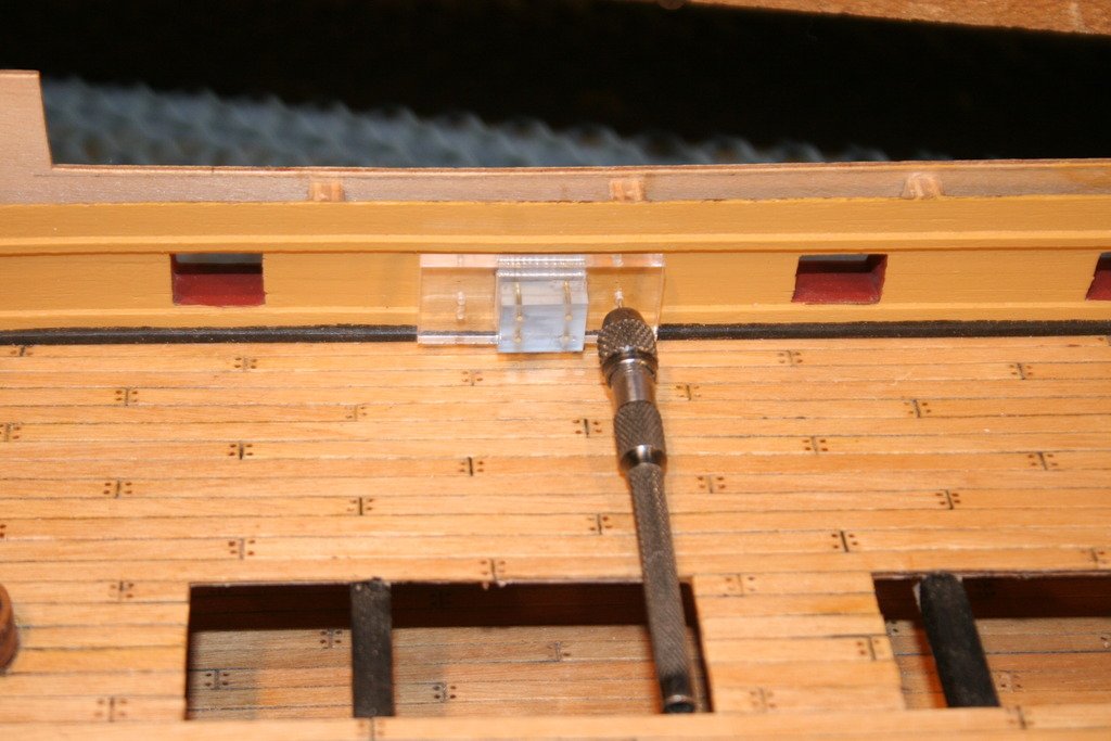
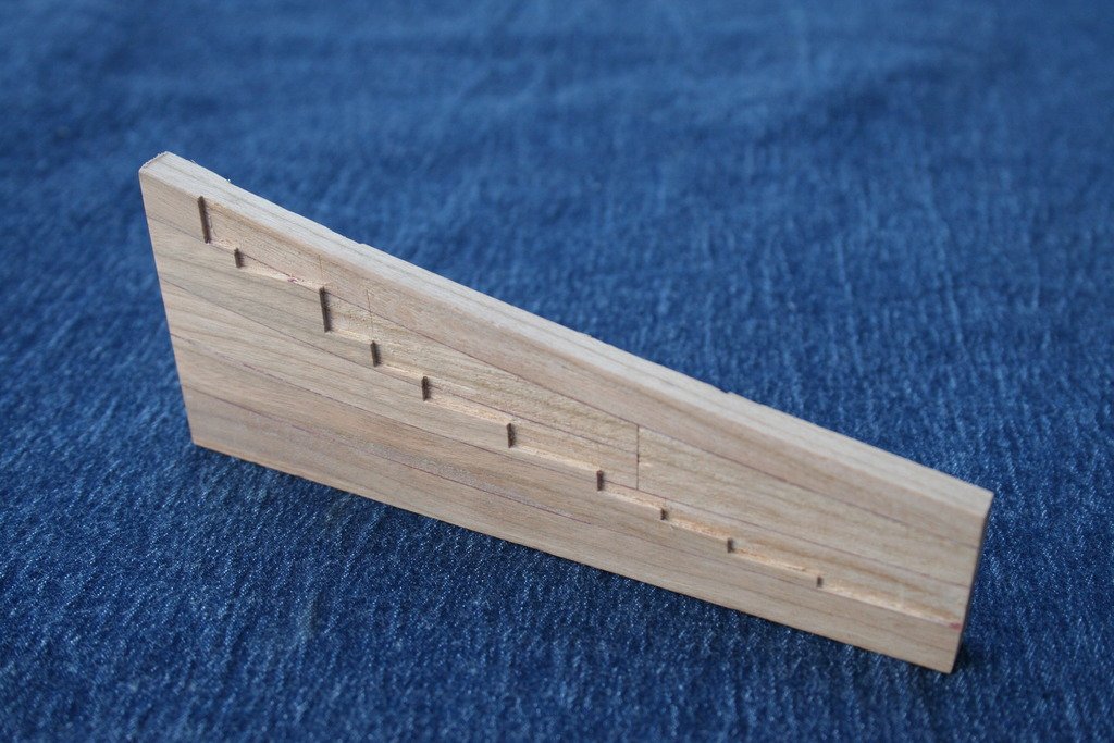
A quick up-date........ After a bit or re-organisation the workshop now has an area dedicated to the Triton build. The first frame has now been completed. I'm thinking about adding some pegs (tree nails?) Assuming that these would have been about an inch in diameter on the original my calculations come out at a gnats whisker over 0.5 mm diameter. I'll try and source some brass wire and see how it goes. I played safe and worked on a frame from the centre of the hull (0). It currently has excess material at the top which will be trimmed later, but in the meantime this provides support for the acrylic brace that I hope will prevent any movement in the wood. I've also had a go at making a height gauge for transferring vertical measurements from the plan to the model. Cheers for now, Graham.

- 41 replies
-
- 12
-
-
Pleased to have been of some help. I'll be heading over there myself sometime in the near future...... but be warned - so much beautiful timber, so much temptation ....... enjoy!
-
No apology necessary, Pav - sharing knowledge and experience is what this site is all about. I just wish I was in a position to be able to provide a fully informed answer! My initial thought when considering what to say in reply was that although I've seen it mentioned by other builders I have never come across a piece of basswood, yet alone used it. A quick 'google', however, has revealed that basswood is another name for lime (which just goes to prove that you never stop learning, even in my profession and at my advanced years!), a timber I have used in the dim and distant past for carving. Luckily we are blessed with members on this site who do know their stuff so a respectful nod to Dan and thanks for fielding your question. I am in full agreement with his reply. I'm using cherry for the first time on this model and have found it relatively easy to work and shape. I made the decision to use it based on the advice of other builders. It finishes nicely but a little care is needed when using power sanding tools, such as disc sanders, to avoid scorching and darkening especially on end grain. The same advice is true for many of the denser hardwoods. As for sourcing it - have a look at Surrey Timbers Ltd on-line site. I have mentioned them before in the 'UK Timber Suppliers' pages in the 'Wood Discussion'section. Hope this helps - and I look forward to seeing progress with your build. Cheers, Graham.
-
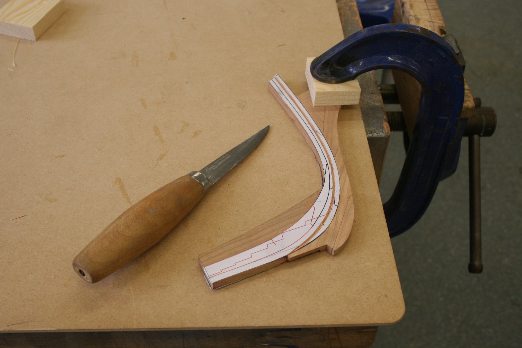
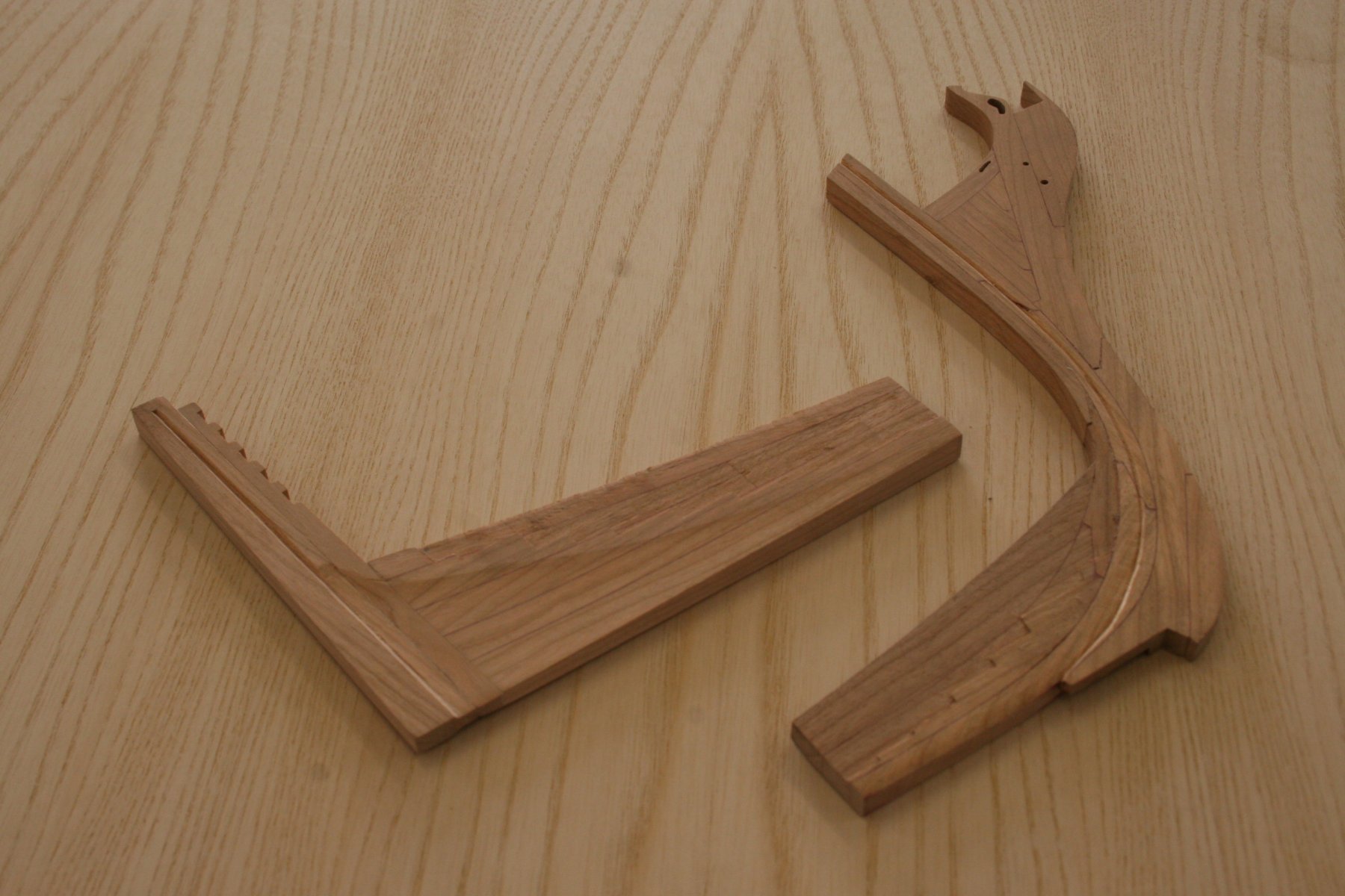
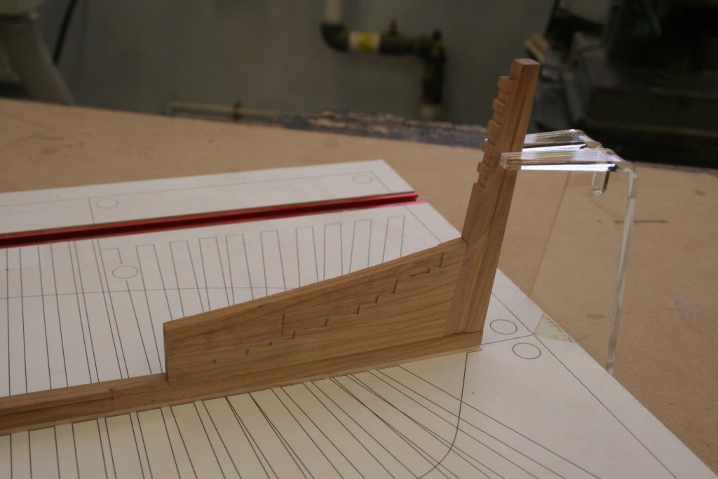
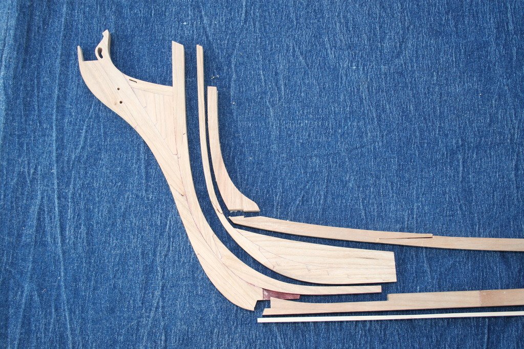
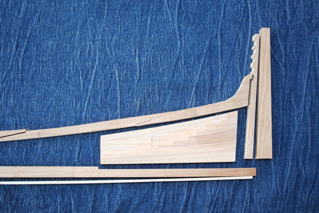
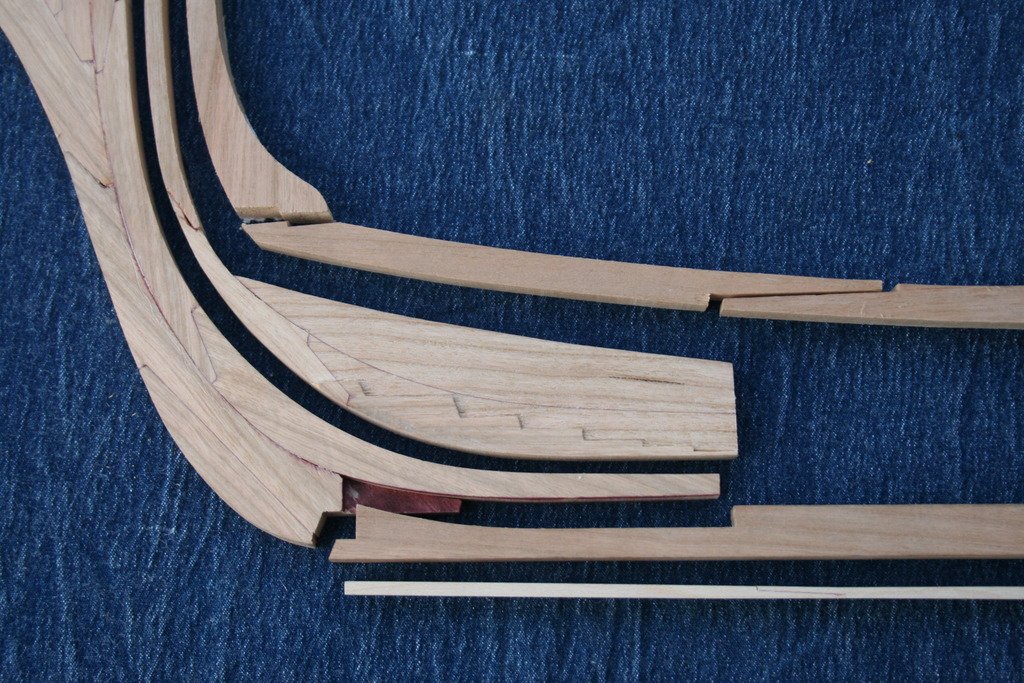
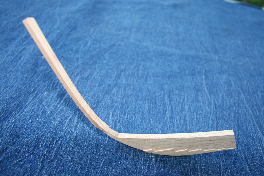
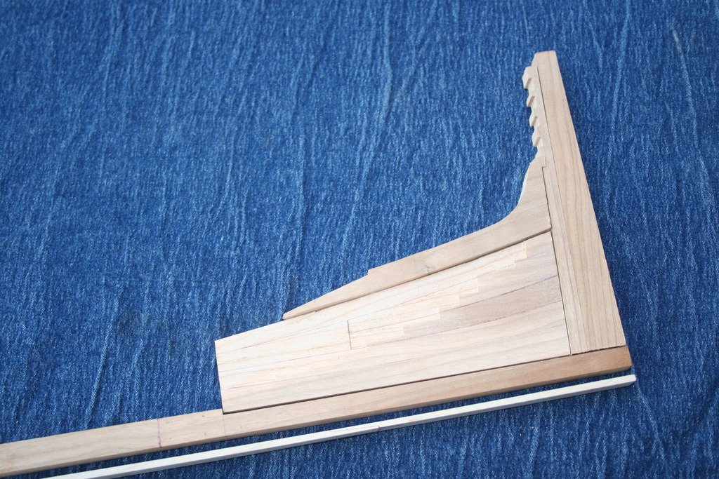
Hi, Now that the dust has settled on the start of a new school year I've managed devote a bit of time again to this project and have made some more progress ...... Shaping the fore and aft deadwoods was holding me up a bit as I tried to make sense of the various sectional profile drawings. My inexperience was evident as I tried to juggle the various profiles and much time was spent working through the other build logs in this section. They certainly helped, and then I came across and followed the link that Dan Vad mentioned in a post referring to his HMS Vulture build. This proved to be a great help and I can see myself visiting this regularly as my build continues - thank's Dan! In the end you just have to dive in and have a go... Using a combination of thin brass sheet and acrylic templates pinned to the aft deadwood the sides were reduced to the required shape. My first attempt at tapering the lower end of the inner post was not as successful as I had hoped so a second had to be made. The rebates were then cut in the stern post with a scalpel and lower area worked to match the ajoining components prior to being glued together. A carving knife proved an effective way to cut the curving rebate in the stem and subsequent shaping of the fore deadwood. I expect there will be a bit more work ahead on these later. At last we have a keel! ... and work begins on the frames ...... Cheers, Graham.


- 41 replies
-
- 14
-
-
Hi Paul - welcome back! I look forward to seeing the progress you are making. I too have given up on PB. I did find that I could download photographs from my PB 'library' onto a memory stick and then upload them from there into my build log. I did it this way originally as I was under the miss-conception that the photo files would be too big to add directly and that by putting them through the hosting site reduced the size. IT is not a strength of mine! These days I simply save the pictures straight from my camera onto my laptop and upload from there using this site's software. All very straight forward, although my aging DSLR has about half the megapixels of today's modern wonders .... Good luck! Graham.
-
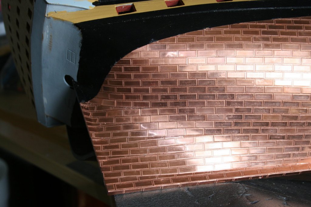
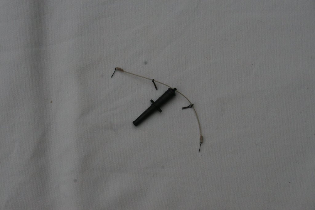
Hi, Other commitments and the odd curve ball that life can throw at you sometimes has slowed progress recently. I have, however, made a little more progress so here's an update. The starboard stern plating has now been completed and the bow is close to completion. I must admit that there have been some sessions where I seemed to be picking more plates off than I was putting on but I'm fairly happy with the result so far. Finishing along the waterline and adding the 'stealers'(?) into the pattern was challenging at times as well as time consuming. As bit of a break from this section of the build I decided to have a go at working out how to produce some of the rigging on the gun carriages. Following David's (ShipyardSid) advice to Robert(22564) I threaded the appropriate eyelets etc. onto the rope before these are later fitted to the carriage and ceiling. The ends of the rope were then bound with thread. Right ...... back to plating ..... Cheers, Graham.
-
Beautifully crisp and accurate craftsmanship as always, Robert. A genuine source of inspiration! Keep up the good work - a pleasure to follow the progress you are making. Graham
- 527 replies
-
- 2
-
-
- caldercraft
- victory
- (and 1 more)
-
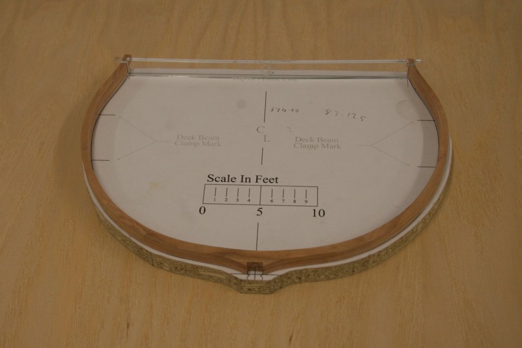
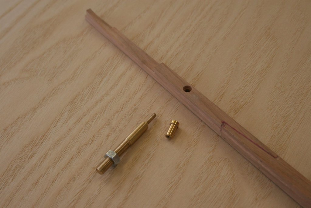
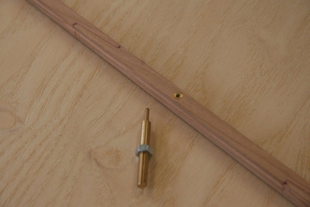
Thanks for sorting this out for me Dan. I've been a regular viewer of your IJN Amatsukaze build - incredible! I never realized that card models of this sophistication even existed... I've managed to make a little more progress with the Triton build in between the demands of a couple of other projects. The scratch stock did the job and both the keel and false keel have now also have had their ends tapered. I turned three brass screws to hold the keel in place on the building board (and later onto a display base although that's many years away!). Brass bushes where also turned and pressed home into the keel. Keel and false keel are now joined ..... ....and the building board, now complete with a print of the jig plan, has been drilled in readiness for the keel once it has been completed. Cheers, Graham.

-
Thanks Chuck - your swift response is appreciated! Graham
-
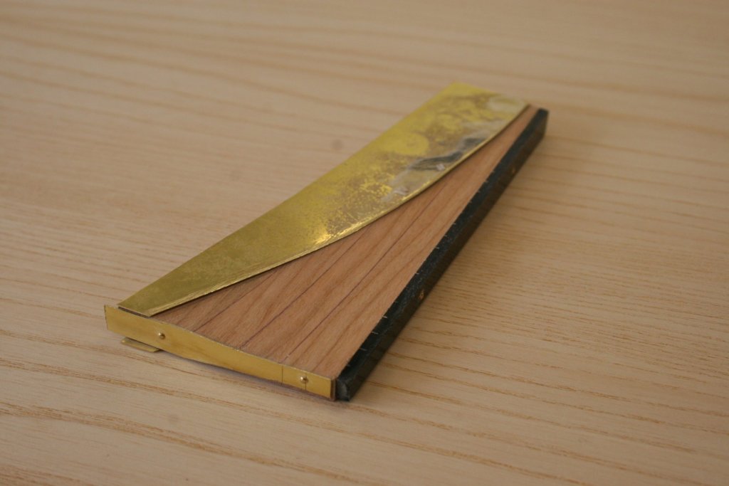
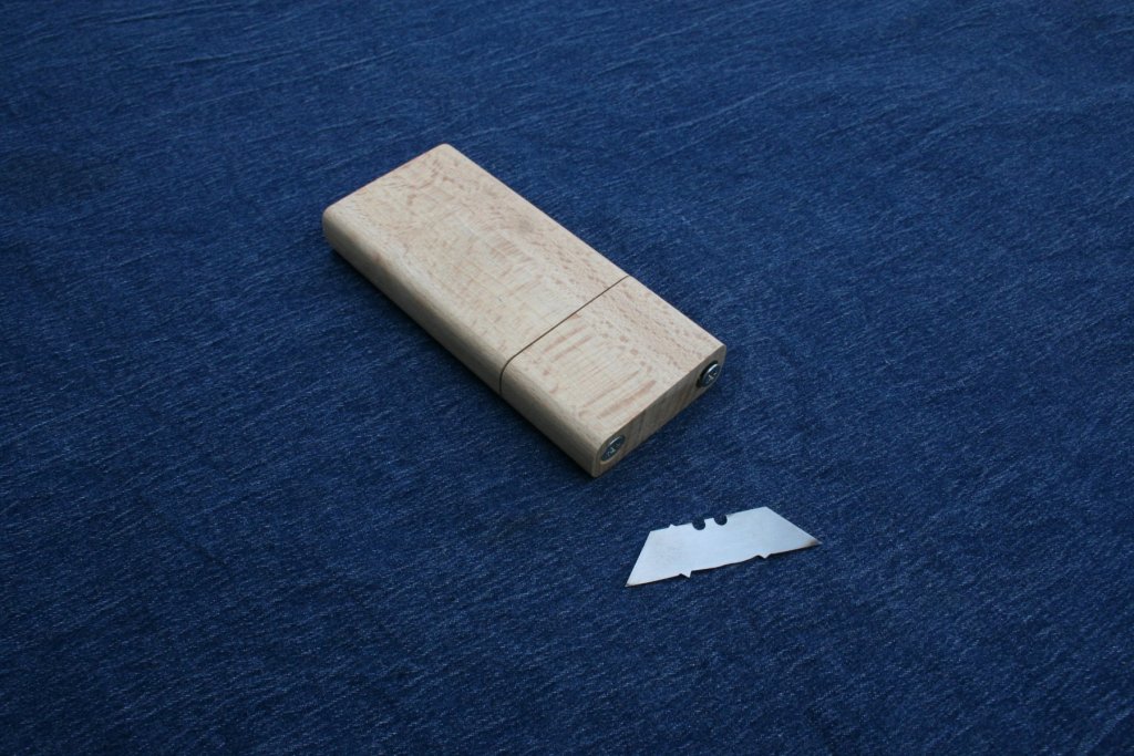
Hi, Bill – thanks for dropping in. I’m building to a scale of 1:48 as per the plans. I forgot to put this in the original thread title and was unable to find a way to edit it. I’ve now resorted to adding it as a tag label. A quick up-date:- The great news of the re-opening of the Triton build topic and the changes in how to now access the plans arrived while I was way on a family holiday. Dealing with this was the first job I did upon my return! The plans are superb – some sheets are genuine works of art. Thank you if you were involved in their production. So much time, care and effort has clearly gone into them. Very much appreciated. Today I invested in having all the AO and A1 sheets printed as I cannot do this for myself unlike the A4 sheets. I have found much information to assist with the task of shaping deadwoods, stern and inner posts etc. Looking at the grooving in the keel sides I decided to spend a bit of preparation time making a basic scratch stock to add this detail. The stock is beech and the blade was fashioned from a heavy duty craft knife blade. Three different ‘spurs’, to deal with the variations in angles shown on the plan, were initially ground to shape with a Dremel and then honed on a water-cooled grindstone. A quick trial on an offcut of cherry proved successful. I’ve been checking the list of plan files in the ‘Complete Model’ download section against the list provided further up in the download area and have found a bit of discrepancy. On the plus side there are many additional files covering areas such as Great Cabin sash lights, Hawse, Hawse and Bollard timbers. Although most of the files I initially thought were missing were actually available by looking in the 'Cross-section' build version download area, I have not yet been able to locate the following: Belfry layout Binnacle Capstan details Capstan Layout Triton stove Wheel Stem Tapered keel Starboard Stern Timbers (1-3) Tafferel Rev 1 (????) Rudder Rudder iron work Are they ‘hiding’ on other sheets perhaps? My inexperience could well have led to me overlooking them of course. Is there any way to obtain them? Any advice gratefully received. Cheers for now. Graham.

-
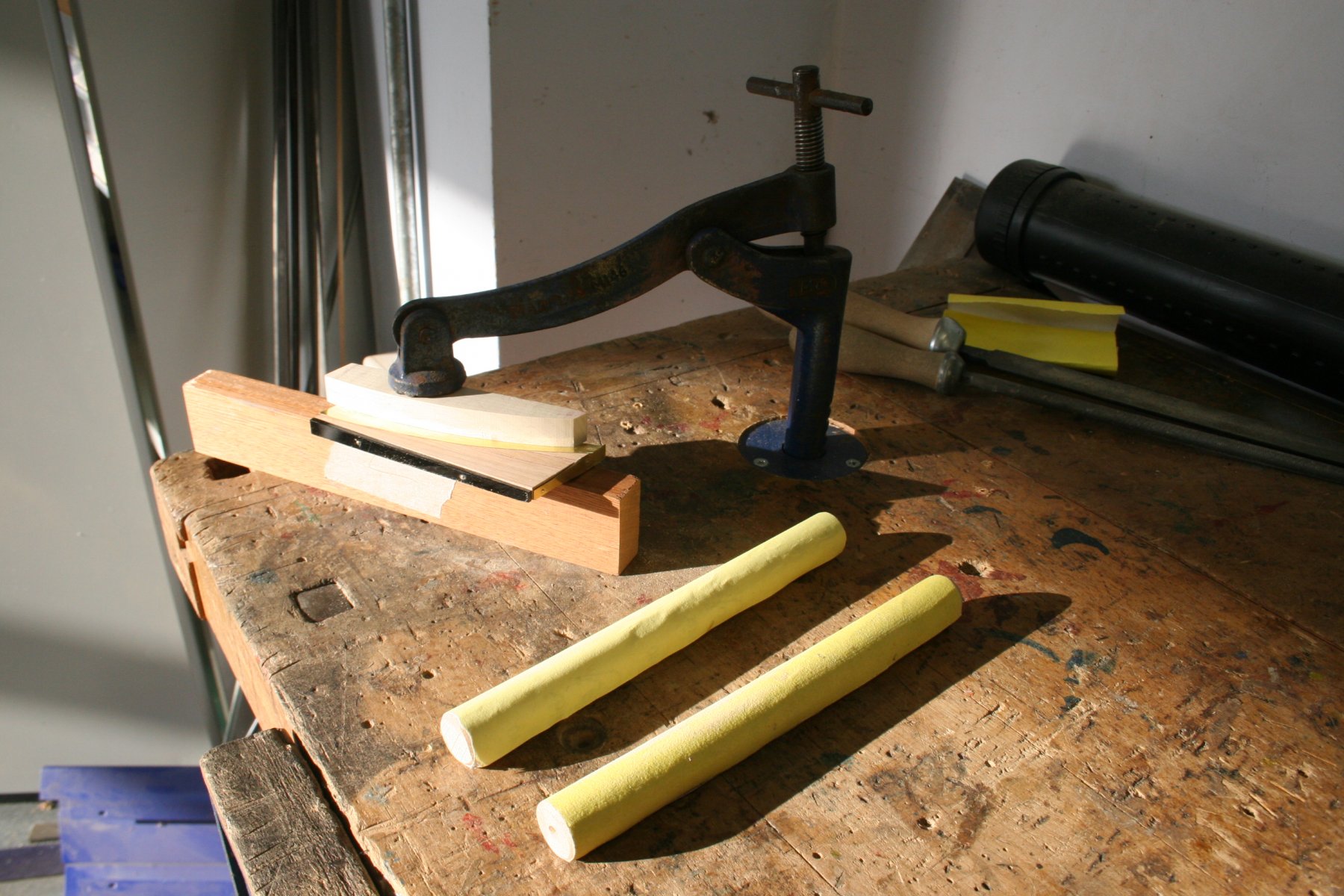
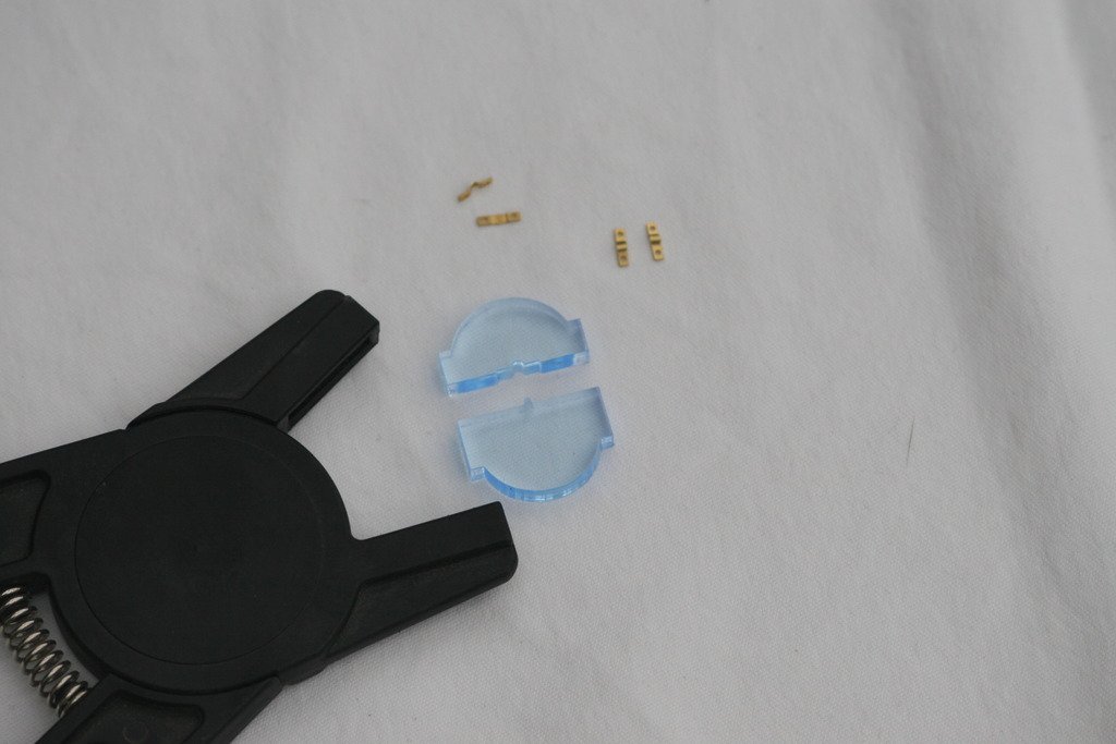
Hi, A couple of diverse reasons for this up-date ... Firstly - Robert, thank you for the compliment about my jigs and this post also includes a very simple one. I'm a regular visitor to your build and love the quality of your model and agree with your decision to leave your hull planked and copper plate free - that skillful work needs to be seen to be fully appreciated! The second purpose is the result of the dreaded PB changes to my account, third party hosting etc. and an attempt to see if I can still access and use my photos. I only use PB as a simple means to 'size' my pictures - I have found that by just up-loading pictures and then re-saving them on a memory stick, and using the latter as the source to add the photos to my posts, the pictures can be added without the need for any more adjustment to meet the required parameters. To be honest I struggle with image manipulation software at times. It appears that I can still use PB successfully, frustrating as the adverts and 'pop ups' are. Yes, I could pay to avoid them, but I'd rather be investing the money in materials and tools. This approach, however, and my reluctance to embrace change is in some ways a reflection of a phobia of the new .... time to have a go at uploading directly through the MSW route I think, after all how hard can it be? - next time... As a break from copper plating I decided to look at the mounting of the cannons and to complete the construction of a gun carriage to check out the assembly process. This jig was made to help with marking the position of the eyelets either side of the gun ports. I've added additional rings to the sides of the carriages to make the run of the ropes more like the real thing, as many other builders have done. An improvised 'draw plate' helped reduce the size of the end of the loop that then holds the guide ring. The assembly of the carriage was very straight forward and presented no major issues, but those eyelets (480) are so small! I swear that there is nothing wrong with my eyesight - but my arms must have shrunk as they are no longer long enough to be able to hold small components in focus. Time to visit the optician again .... Cheers, Graham.
-
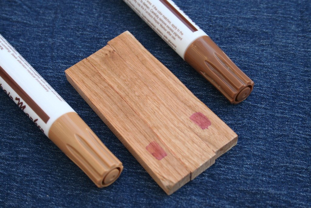
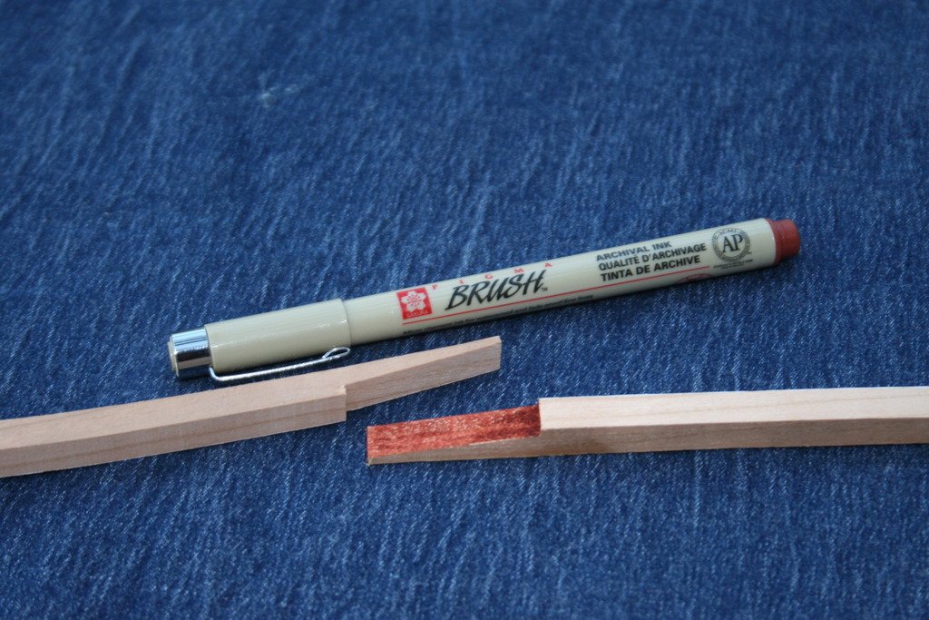
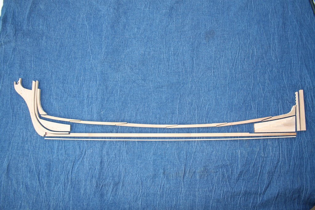
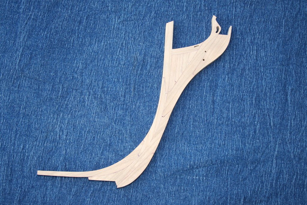
Hi, The Furniture scratch repair pens arrived .... three different browns euphemistically labeled mahogany, oak and cherry. The first was as dark as the marker pen I used previously on the aft deadwood, the other two, shown above, were very similar to each other but do not match the woods they are named after, to be honest. The cherry, on the left, was the best of the bunch and it was this that I used on the second attempt at the deadwood and various scarf joints. It would be wrong of me to criticize these pens without actually trying them for their advertised purpose, but with a working knowledge of furniture restoration and various finishing technique including French polishing there are other processes I'd use to repair scratches first. The effect of this pen was generally okay although it does have a tendency to bleed, especially on end grain. Then I came across Dan Vad's advice to Jeff (Zarcon) on his HMS Victory build log about using Pigma Brush pens and archival ink. More than twice the price of the set of three, but so much better - and worth every penny! I'll be using this for the rest of the build. I have now completed cutting out all the components for the keel etc. My next task is to add the rebates and additional tapering to the fore and aft deadwoods, referring to the first plan sheet and the other build logs in this forum - I love a challenge! Once this has been done, and the parts have been assembled, I hope to be in a position to access the full set of sheets. Cheers, Graham.
- 41 replies
-
- 17
-
-
Thank you , Steve, for pointing me in the right direction! Cheers, Graham
-
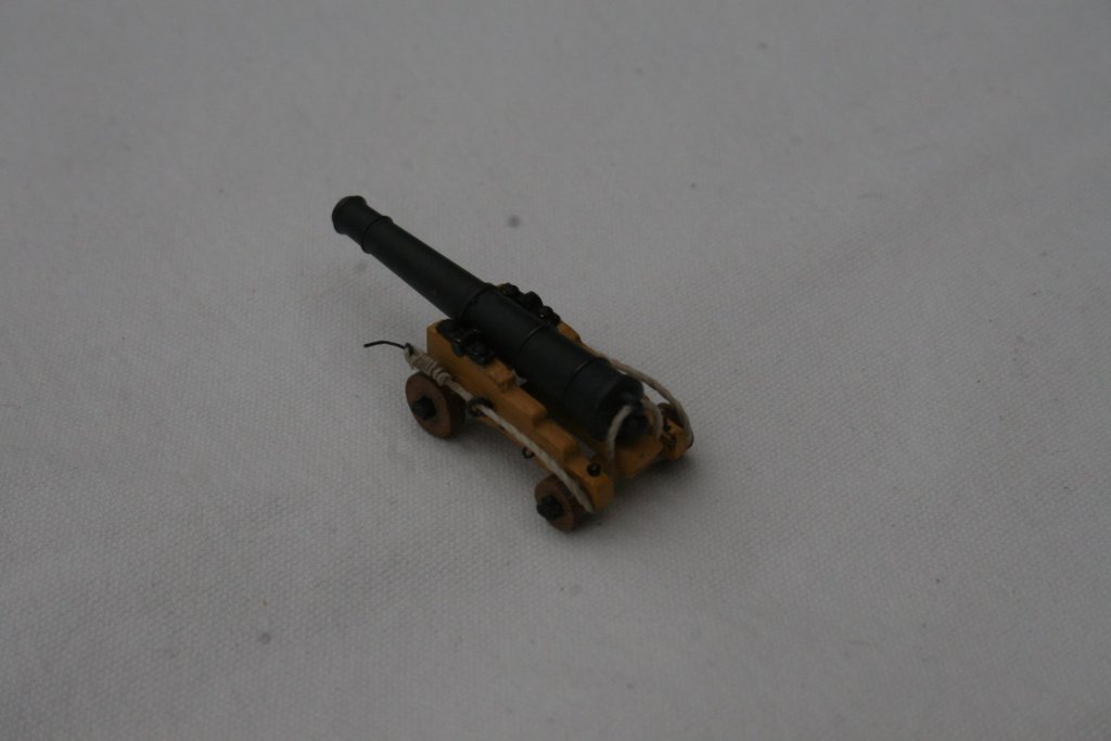
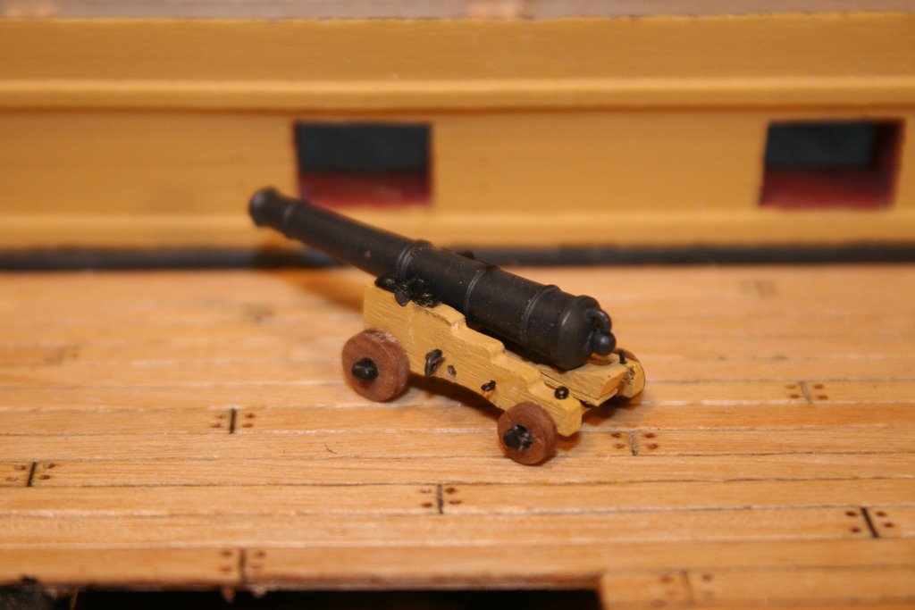
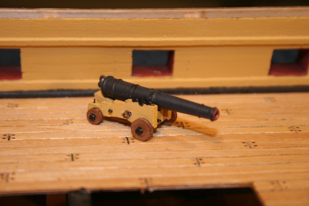
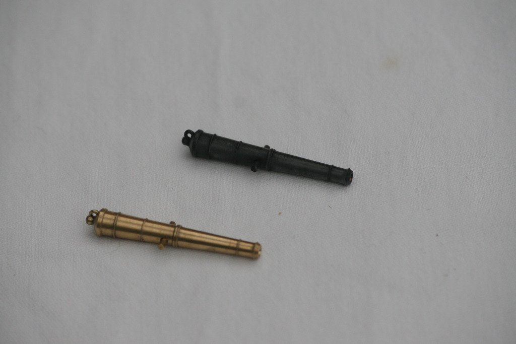
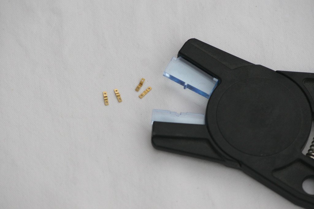
Hi, While work continues with copper plating the starboard side of the hull I've also turned my attention to the cannons and their carriages. Having found a way to assemble the carriages I started work on researching how to set about applying a painted finish to the cannons. An initial request for advice on spraying led to a whole new approach (see the thread in the 'Painting, finishes and weathering techniques and products' ) and subsequently the finish is now achieved using 'Brass Black'. To reliably form the trunnion clamps I resorted to making a new pair of jaw inserts for my Mantua plank bending pliers. With this tool I've also been able to replicate the slight left and right hand bias that these clamps need to compensate for the tapering sides of the gun carriages. Cheers, Graham.
-
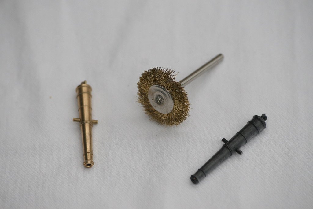
When I started this topic the other day I had no idea that it would end up going in this direction. Proof once more of the value of this forum when it comes to sharing ideas and techniques. Thank you to all those who have contributed to and followed the discussion. With the resources now in place I managed to find time do a trial run :- - before and after .... After brushing and de-greasing, two 30 second immersions in the Birchwood Casey 'Brass Black', with a rinse and dry in between, I ended up with the finish shown above. This was followed by a coat of matt lacquer. I am delighted with the result to put it mildly! Cheers, Graham.
-
Thank you for your input on this topic, Toni. The brushes I ordered are brass ones, so as not to contaminate the brass cannons, and were waiting for me at work this morning, together with the blacking solution. A quick trial with the brush shows that it actually refines and polishes the surface. I'll see if I can source the chemicals and do a trial shortly. Cheers, Graham