
MORE HANDBOOKS ARE ON THEIR WAY! We will let you know when they get here.
×

Erebus and Terror
-
Posts
410 -
Joined
-
Last visited
Reputation Activity
-

 Erebus and Terror got a reaction from kier in HMS Terror by Erebus and Terror - FINISHED - Scale 1:48 - POB - as fitted for polar service in 1845
LASER CUTTING TERROR’S BULKHEADS
I have arrived at the stage of my build where I am assembling the bulkheads that will give shape to the ship’s hull. I have already created bulkheads for this model using the traditional method – gluing the plans to plywood and cutting them out using a scroll saw.
The old bulkheads - cut using a scroll saw (prior to sanding).
However, I recently decided to change the way I will construct the bow of the model. I had originally modified the forward stations to account for the extra bolsters and planking at the bow, but I've recently decided to try to build these fittings (as a means to determine how Rice actually reinforced Terror against the ice). This necessitated rebuilding the two most forward station bulkheads.
And this gave me an excuse for a whole new mini-project.
Following a current trend, my local public library recently opened a prototyping studio, which includes design software, 3D printers, and an Epilogue Mini 24 Laser Cutter. The library allows you to book the equipment for several hours each month - for free. I've wanted to experiment with a laser cutter for some time, and since I needed to make new bulkheads anyway, I decided to recut all of them. My hope was that it would result in a more accurate build.
The Epilogue Mini 24 Laser Cutter. The bed capacity is 12" x 24".
The cutter works very much like a traditional printer and will engrave (raster) or cut (vector) based on the thickness of the lines shown in the image file (I used high resolution PDFs for this). My first attempt, using factory recommended settings, was somewhat of a disaster, resulting in charred and smoldering wood and unusable pieces (plywood is notoriously difficult to cut because of its inconsistent composition).
My first disastrous attempt. Note the burned and charred edges.
For my second attempt, I conducted some tests and determined the proper power settings needed to cut 5mm plywood with the thinnest, most accurate, cuts and a minimum of charring and burning [1].
As a test, I cut a series of discs with different power settings.
The appearance of the cut edge with the proper settings (no charring).
I engraved the station markings on each bulkhead. The machine automatically engraves before cutting.
The bulkheads being cut.
You can tell the cut was successful if the part drops away from the sheet.
A finished sheet.
Each bulkhead fits into slots on the false keel.
The bulkheads slide snugly into place.
Test assembly proceeds. This is just a dry -fit.
The bulkheads dry-fitted in place. They need to be properly aligned, but I'm
happy with the run already. Mini-Crozier allows us to visualize how large
Terror actually was (quite small for a Royal Navy vessel).
A view from the bow.
This view shows the run of the ice channels very nicely.
A top-side view from the stern. The bulkheads are just dry-fitted
here and will need to be aligned properly before gluing.
I am very pleased with my experience using the laser cutter. The bulkheads are much more accurate than I could have produced by hand, and the process took about a tenth of the time normally required to cut and sand these parts. I will certainly be using it again when I need to cut more complex shapes and components for my build.
Footnotes:
[1] For those interested, low speed, power, and PPI settings are a must, and the recommended wood settings for the Epilogue Laser will not work on plywood. Your goal should be a setting that will just barely cut completely through the wood, as this results in the thinnest cuts and edges that are browned, but not charred. My settings for good quality 5mm birch plywood were: Speed = 10, Power = 38, and PPI(Frequency) = 150.
-
 Erebus and Terror reacted to archjofo in La Créole 1827 by archjofo - Scale 1/48 - French corvette
Hello,
many thanks for your nice comments.
By the way, that's not a 18 pounder, but a 30 pound carronade.
After burnishing is the "Baille à Drisse" completed.
Equipped with a coil of rope, it looks like this:
-
Erebus and Terror reacted to AntonyUK in HMS Terror by Erebus and Terror - FINISHED - Scale 1:48 - POB - as fitted for polar service in 1845
Hi E&T.
Nice to you back at the tools again.
That's some very nice modeling skills you got going there
WOW. Wish our library had resources like that... But that's the UK for you. Back to the stone age.
I love the way you take photos of the stages you are on..
Looking forward to your next post.
Regards Antony.
-
 Erebus and Terror got a reaction from Jorge Diaz O in HMS Terror by Erebus and Terror - FINISHED - Scale 1:48 - POB - as fitted for polar service in 1845
LASER CUTTING TERROR’S BULKHEADS
I have arrived at the stage of my build where I am assembling the bulkheads that will give shape to the ship’s hull. I have already created bulkheads for this model using the traditional method – gluing the plans to plywood and cutting them out using a scroll saw.
The old bulkheads - cut using a scroll saw (prior to sanding).
However, I recently decided to change the way I will construct the bow of the model. I had originally modified the forward stations to account for the extra bolsters and planking at the bow, but I've recently decided to try to build these fittings (as a means to determine how Rice actually reinforced Terror against the ice). This necessitated rebuilding the two most forward station bulkheads.
And this gave me an excuse for a whole new mini-project.
Following a current trend, my local public library recently opened a prototyping studio, which includes design software, 3D printers, and an Epilogue Mini 24 Laser Cutter. The library allows you to book the equipment for several hours each month - for free. I've wanted to experiment with a laser cutter for some time, and since I needed to make new bulkheads anyway, I decided to recut all of them. My hope was that it would result in a more accurate build.
The Epilogue Mini 24 Laser Cutter. The bed capacity is 12" x 24".
The cutter works very much like a traditional printer and will engrave (raster) or cut (vector) based on the thickness of the lines shown in the image file (I used high resolution PDFs for this). My first attempt, using factory recommended settings, was somewhat of a disaster, resulting in charred and smoldering wood and unusable pieces (plywood is notoriously difficult to cut because of its inconsistent composition).
My first disastrous attempt. Note the burned and charred edges.
For my second attempt, I conducted some tests and determined the proper power settings needed to cut 5mm plywood with the thinnest, most accurate, cuts and a minimum of charring and burning [1].
As a test, I cut a series of discs with different power settings.
The appearance of the cut edge with the proper settings (no charring).
I engraved the station markings on each bulkhead. The machine automatically engraves before cutting.
The bulkheads being cut.
You can tell the cut was successful if the part drops away from the sheet.
A finished sheet.
Each bulkhead fits into slots on the false keel.
The bulkheads slide snugly into place.
Test assembly proceeds. This is just a dry -fit.
The bulkheads dry-fitted in place. They need to be properly aligned, but I'm
happy with the run already. Mini-Crozier allows us to visualize how large
Terror actually was (quite small for a Royal Navy vessel).
A view from the bow.
This view shows the run of the ice channels very nicely.
A top-side view from the stern. The bulkheads are just dry-fitted
here and will need to be aligned properly before gluing.
I am very pleased with my experience using the laser cutter. The bulkheads are much more accurate than I could have produced by hand, and the process took about a tenth of the time normally required to cut and sand these parts. I will certainly be using it again when I need to cut more complex shapes and components for my build.
Footnotes:
[1] For those interested, low speed, power, and PPI settings are a must, and the recommended wood settings for the Epilogue Laser will not work on plywood. Your goal should be a setting that will just barely cut completely through the wood, as this results in the thinnest cuts and edges that are browned, but not charred. My settings for good quality 5mm birch plywood were: Speed = 10, Power = 38, and PPI(Frequency) = 150.
-
 Erebus and Terror got a reaction from popeye the sailor in HMS Terror by Erebus and Terror - FINISHED - Scale 1:48 - POB - as fitted for polar service in 1845
ASSEMBLING TERROR’S STERN
(Or, finally some sawdust!!!)
I haven't posted an update regarding my model in several months. While I've kept busy with side projects, the real reason for my delay is that I had reached an impasse with Terror’s stern.
As I've discussed in previous posts, the sterns of Franklin’s ships were modified in 1845 to accommodate a new auxiliary screw propulsion system – to be used as a time saving device “providing the wind should prove contrary or a dead calm”. There are two sources of data on these modifications: Oliver Lang’s original design plan, and its counterpart, a contemporary model of the design. I had purchased full resolution copies of the plan many months ago, but unfortunately Lang did not include a cross section in his draught. That information could only be gleaned from the contemporary model held at the National Maritime Museum’s storage facility in Chatham.
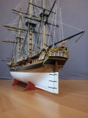
The contemporary model of Oliver Lang's 1845 design.
National Maritime Museum, Greenwich, London (SLR2253 [L2251-001]).
Used under Creative Commons Attribution-Non-Commercial-ShareAlike (CC BY-NC-SA) license
Fortunately, I recently had an opportunity to visit the Chatham model ship facility. Assisted by the expert curators, I was able to study the stern model in detail. It is quite unique, being constructed using a series of carved blocks arranged to conform to the position of major structural and engineering elements of Lang’s design. The information I gathered has allowed me to complete my construction of the stern; below, I’ll reveal the new information I've learned from the contemporary model, while documenting my final assembly of Terror’s stern:
1) The propeller well used to raise and lower the screw was rectangular, almost square-sided, with the sternpost and rudderpost forming the fore and aft sides of the well, respectively. To accomplish this, thick timbers were bolted to the sides of the rudderpost and sternpost. The rudderpost bolsters were much more complex than I originally assumed and were each constructed of at least two pieces, with the lower portions tapering gently to the width of the rudderpost, following the lines of the body plan (see here for my original conceptualization of the design).
The stern pieces prior to assembly. The bolster on the left is the old design I intended to use,
which was incorrect.
The overkill method I used to glue the bolsters to the stern and rudderposts.
Thankfully this was just a dry-run (note the older bolster design).
The new bolster timbers glued on the rudderpost. Note the groove for the "Lihou" rudder on the
rudderpost. I may need to sand the bolsters somewhat to match the run of the planking as they
may be slightly oversized - but no by much.
Another angle showing the bolster timbers on the sternpost.
The NMM model shows that the bolsters on the rudderpost are
longer than those on the sternpost.
2) The rudderpost and sternpost were each tenoned into the keel extension, as was typical, but each was secured with a single bolt, which was not indicated on Lang’s plan.
Marking the precise position of the tenon bolts.
The bolts were simulated with 20 gauge copper wire, precisely the
same as that used on the keel scarphs.
3) The propeller well was framed on the port and starboard sides in three distinct sections. The upper section included stout rectangular framing fayed to the deck beams, which formed a ledge for a scuttle on the upper deck. Below this, the well was probably enclosed by watertight planking down to the height of the stern timbers. Because of the construction of the contemporary NMM model, such planking was not shown, but it is unlikely that solid timber pieces would have been used, as these aren’t shown in contemporary models.
The heavy framing used to form the top of the propeller well.
The upper part of these timbers formed a lip for a scuttle to the well.
Planking on the upper section of the well. I've estimated a width of 12 inches.
The actual width is unknown. Note that this section of the model will be covered
so I haven't simulated bolts or spikes here.
A view of the topside of the well. The upper pieces of the sternpost
and rudderpost bolsters will be trimmed at a later stage of the build,
but are useful for alignment at this stage.
4) A new section, clearly visible in the well of the model, started at the position of the stern timbers. This suggests the stern timbers were bolted to the sides of the rudderpost and sternposts to provide major structural support to the new rudderpost and well. This makes good sense, and Lang’s 1845 stern plan clearly shows the stern timbers as a major element of the design. In fact, these new timbers are substantially more robust than Terror’s original stern timbers, suggesting they were an integral part of the strength of the new structure. Again, this type of structure is supported by contemporary models.
The bottom portion of the framing planks were trimmed to match the run
of the stern timbers. Note the rabbet on the rudderpost on the right.
5) The lower section of the propeller well was composed of the second layer of hull planking where it ran aft, horizontally. Eventually, the run of the higher planks would have veered away from the straight-sided wall of the well. At this point, straight horizontal planking would have been used to frame the sides of the well. The position where this occurs is marked by a block seam on the contemporary NMM model.
Unfortunately, Lang’s contemporary model does not include any of the ironwork used to strengthen the stern, nor does it include the propeller rail/track mechanism. I've based these portions of the model on Lang’s plans and extensive research on other contemporary models and designs. This research is outlined in several blog posts (and here, here, and here).
Oliver Lag's stern design. Note the extensive ironwork and the propeller systems.
National Maritime Museum, Greenwich, London (ZAZ5683 [J1529]).
Used under Creative Commons Attribution-Non-Commercial-ShareAlike (CC BY-NC-SA) license.
The iron staple knee glued in place. The knee provided essential support for the rudderpost.
Mini-Crozier inspects the staple knee in dry dock.
Lang used iron strapping to further reinforce the stern structure. Here they are made from
chemically blackened copper.
Each strap was glued in place and then the bolt holes were drilled out by hand.
Bolts glued in place. These were simulated using blackened brass.
Another view of the completed iron work.
Mini-Crozier frets over the modifications.
The staple knee was protected by a fitted chock bolted to the keel section.
I carved this using a simple chisel blade.
The finished chock compared to the plans.
Image showing how the chock fits over the knee. Unfortunately it had to
be glued in place to permit the propeller rails/tracks to be installed.
At least I know the knee is there.
The chock glued in place.
The propeller was raised and lowered using rails or "tracks". These have been
modified slightly from my original versions based on new data. Copper bolts
were simulated using wire.
The rails glued in final position. Note the rabbet on the rudderpost
for the second layer of hull planking. The rabbet will be modified to
accommodate the precise run of planking when it is installed.
View of the rails installed on the sternpost.
View of the rails installed on the rudderpost.
Another view.
Wooden bolt plugs added to the chock. The bolts were "counterbored and plugged".
The staple knee was bolted to the rudderpost; these bolts were also counterbored
and plugged. I'm not entirely happy with the contrast here and may redo them at a later date.
The completed stern assembly.
Lowering the screw propeller in place (it raise and lowers - and the propeller spins).
The propeller in position. Unfortunately the angle of the photo makes it
look slightly crooked, but it is not - is spins freely, with very small
tolerances as shown on Lang's original plans.
A view from the stern.
Another angle showing how the propeller was seated.
Looking down the well from the position of the upper deck .
Mini-Crozier contemplates how the stern will fare in the ice.
How successful was Lang’s stern at protecting the ship from the pack ice? Parks Canada divers are assessing that currently, and with luck they’ll find the answers soon. We know from historical sources that the Admiralty was concerned about the strength of the design, and that while Lang believed the “sternposts” (sternposts and rudderposts) were as strong as those on other ships, he would not certify that the strength of the filling chocks was sufficient to protect the Erebus and Terror [4].
No matter how vulnerable it made the ship, we can suspect that Lang’s radical redesign also altered the sailing qualities of Terror. Contemporary sailing reports indicate that Vesuvius class bomb vessels were rather lumbering and could not carry sail well, and Ross reported that Terror was constantly falling behind Erebus during his Antarctic voyage, delaying and endangering the expedition.
Recently, Regina Koellner, assisted by William Battersby, transcribed a letter from Francis Crozier to his friend John Henderson, written shortly after the ships arrived at Whalefish Islands in Greenland. In the letter, Crozier provides a brief report of Terror’s sailing qualities: "Our steering is decidedly improved by the alterations on the counter we now sail much more evenly with Erebus which is advantageous to us in many ways." I suspect that the effective lengthening of the keel to accommodate the propeller allowed Terror to sail closer to the wind, finally permitting her to keep up with the more nimble Erebus. It seems the final conversion of Terror to screw propulsion made her a more capable vessel under sail, an irony certainly not lost on Crozier.
-
Erebus and Terror reacted to IgorSky in Colin Archer by IgorSky - FINISHED - scale 1/230 - BOTTLE - Lifeboat RS1
After lot of attempts to make running lights...
-
Erebus and Terror reacted to IgorSky in Colin Archer by IgorSky - FINISHED - scale 1/230 - BOTTLE - Lifeboat RS1
Thanks Pete and all who put on the button Like for your interest to this project!
The smal, very smal today's progress:
Best Regards!
Igor.
-
Erebus and Terror reacted to IgorSky in Colin Archer by IgorSky - FINISHED - scale 1/230 - BOTTLE - Lifeboat RS1
Next small update - I try to make the light windows in the deck
-
Erebus and Terror reacted to mikegerber in Colin Archer by IgorSky - FINISHED - scale 1/230 - BOTTLE - Lifeboat RS1
Hi Igor
... here is a great model photo (RS1, Norsk Maritime Museum, Oslo) - perhaps helpful for the deck layout.
best regards.
Mike
-
Erebus and Terror reacted to mikegerber in Colin Archer by IgorSky - FINISHED - scale 1/230 - BOTTLE - Lifeboat RS1
... It is the chimney of the furnace.
-
Erebus and Terror reacted to IgorSky in Colin Archer by IgorSky - FINISHED - scale 1/230 - BOTTLE - Lifeboat RS1
Hi Mike!
A lot of thanks for these photos! Yes, it seems my winch a little bit similar on real winch ... I think to try to blacken her tomorrow. And I can not figure out what it is (see photo) This is reminiscent to me of the exhaust pipe. O, it seems the winch is behind the mast?
-
Erebus and Terror reacted to mikegerber in Colin Archer by IgorSky - FINISHED - scale 1/230 - BOTTLE - Lifeboat RS1
Hi Igor
I'm sorry, I'm late with my support. Unfortunately I have created up to now still no plans to this topic, but here I send you a few pictures of "Stavanger's" winch, which is almost similar to "Colin Archers's" winch.
As you have already surmised, she is probably slightly too big (but little, appreciated 10 to 15%), but let me say, that I like your small winch - top craftsmanship!
Best regards.
Mike
-
Erebus and Terror reacted to IgorSky in Colin Archer by IgorSky - FINISHED - scale 1/230 - BOTTLE - Lifeboat RS1
Hi everyone!
Many thanks for support and your interest to this project.
Today's morning update - one more winch. Now for the RS-1
Unfortunately I do not have the reliable drawing of this winch, so I trying to do something similar and appropriate size. I have some doubts about the size. It seems it's a bit big for this boat.
Best Regards!
Igor.
-
Erebus and Terror reacted to IgorSky in Colin Archer by IgorSky - FINISHED - scale 1/230 - BOTTLE - Lifeboat RS1
Hi everyone,
Many thanks for good word and Likes!
Today's update:
Best Regards!
Igor.
P.S. Mike, long weekends and non-flying weather provide an essential increase in the rate of construction
-
Erebus and Terror reacted to IgorSky in Colin Archer by IgorSky - FINISHED - scale 1/230 - BOTTLE - Lifeboat RS1
The planking of the deck
-
Erebus and Terror reacted to IgorSky in Colin Archer by IgorSky - FINISHED - scale 1/230 - BOTTLE - Lifeboat RS1
Today's morning small update
-
Erebus and Terror reacted to IgorSky in Colin Archer by IgorSky - FINISHED - scale 1/230 - BOTTLE - Lifeboat RS1
My next small project - lifeboat RS1 Colin Archer
Best Regards!
Igor.
-
Erebus and Terror reacted to BNoah in Fram by BNoah - FINISHED - Scale 1:100 - as she appeared for Amundsen's 1910-1912 South Pole Expedition
April 2, 2015
DECK BITS
My pace has slowed as I concentrate on crafting various parts of the deck furniture. Pictured are the articulated smoke stack, companionways, gratings (about the size of a US Quarter) ladders, ships wheel and rudder gearing. etc. I put each aside so that when they are all completed I can assemble at one time. The second picture is of the components which will make up the bridge which will span the afterdeck and surround the mizzen mast. I will not assemble it until after all of the deck bits have been placed as it has a winch and davits under it.
Next I will work on the ship's boats. I have been dreading these because they seem complicated for me and they are SO small. Now I have to suck it up and face the hurdle.
-
Erebus and Terror reacted to robnbill in Brig Eagle by robnbill - 1:48
I was able to get the bow cant frames installed. Now I can work on the square frames. Yeah! I am happy to have all the half frames/Cant frames behind me. I still need to do a bunch of sanding cleanup on the inside and outside of the cant frames. I left more meat on the bones of these. I found it easier to sand them down than to recut them if I beveled them incorrectly when off the ship.
Anyway, here are a couple of photos on the ship where it stands today. The darker frame is the test frame I built before starting the frames. It is standing where my frame X will be.
-
Erebus and Terror got a reaction from popeye the sailor in HMS Terror by Erebus and Terror - FINISHED - Scale 1:48 - POB - as fitted for polar service in 1845
LASER CUTTING TERROR’S BULKHEADS
I have arrived at the stage of my build where I am assembling the bulkheads that will give shape to the ship’s hull. I have already created bulkheads for this model using the traditional method – gluing the plans to plywood and cutting them out using a scroll saw.
The old bulkheads - cut using a scroll saw (prior to sanding).
However, I recently decided to change the way I will construct the bow of the model. I had originally modified the forward stations to account for the extra bolsters and planking at the bow, but I've recently decided to try to build these fittings (as a means to determine how Rice actually reinforced Terror against the ice). This necessitated rebuilding the two most forward station bulkheads.
And this gave me an excuse for a whole new mini-project.
Following a current trend, my local public library recently opened a prototyping studio, which includes design software, 3D printers, and an Epilogue Mini 24 Laser Cutter. The library allows you to book the equipment for several hours each month - for free. I've wanted to experiment with a laser cutter for some time, and since I needed to make new bulkheads anyway, I decided to recut all of them. My hope was that it would result in a more accurate build.
The Epilogue Mini 24 Laser Cutter. The bed capacity is 12" x 24".
The cutter works very much like a traditional printer and will engrave (raster) or cut (vector) based on the thickness of the lines shown in the image file (I used high resolution PDFs for this). My first attempt, using factory recommended settings, was somewhat of a disaster, resulting in charred and smoldering wood and unusable pieces (plywood is notoriously difficult to cut because of its inconsistent composition).
My first disastrous attempt. Note the burned and charred edges.
For my second attempt, I conducted some tests and determined the proper power settings needed to cut 5mm plywood with the thinnest, most accurate, cuts and a minimum of charring and burning [1].
As a test, I cut a series of discs with different power settings.
The appearance of the cut edge with the proper settings (no charring).
I engraved the station markings on each bulkhead. The machine automatically engraves before cutting.
The bulkheads being cut.
You can tell the cut was successful if the part drops away from the sheet.
A finished sheet.
Each bulkhead fits into slots on the false keel.
The bulkheads slide snugly into place.
Test assembly proceeds. This is just a dry -fit.
The bulkheads dry-fitted in place. They need to be properly aligned, but I'm
happy with the run already. Mini-Crozier allows us to visualize how large
Terror actually was (quite small for a Royal Navy vessel).
A view from the bow.
This view shows the run of the ice channels very nicely.
A top-side view from the stern. The bulkheads are just dry-fitted
here and will need to be aligned properly before gluing.
I am very pleased with my experience using the laser cutter. The bulkheads are much more accurate than I could have produced by hand, and the process took about a tenth of the time normally required to cut and sand these parts. I will certainly be using it again when I need to cut more complex shapes and components for my build.
Footnotes:
[1] For those interested, low speed, power, and PPI settings are a must, and the recommended wood settings for the Epilogue Laser will not work on plywood. Your goal should be a setting that will just barely cut completely through the wood, as this results in the thinnest cuts and edges that are browned, but not charred. My settings for good quality 5mm birch plywood were: Speed = 10, Power = 38, and PPI(Frequency) = 150.
-
 Erebus and Terror got a reaction from MD11pilot in HMS Terror by Erebus and Terror - FINISHED - Scale 1:48 - POB - as fitted for polar service in 1845
ASSEMBLING TERROR’S STERN
(Or, finally some sawdust!!!)
I haven't posted an update regarding my model in several months. While I've kept busy with side projects, the real reason for my delay is that I had reached an impasse with Terror’s stern.
As I've discussed in previous posts, the sterns of Franklin’s ships were modified in 1845 to accommodate a new auxiliary screw propulsion system – to be used as a time saving device “providing the wind should prove contrary or a dead calm”. There are two sources of data on these modifications: Oliver Lang’s original design plan, and its counterpart, a contemporary model of the design. I had purchased full resolution copies of the plan many months ago, but unfortunately Lang did not include a cross section in his draught. That information could only be gleaned from the contemporary model held at the National Maritime Museum’s storage facility in Chatham.
The contemporary model of Oliver Lang's 1845 design.
National Maritime Museum, Greenwich, London (SLR2253 [L2251-001]).
Used under Creative Commons Attribution-Non-Commercial-ShareAlike (CC BY-NC-SA) license
Fortunately, I recently had an opportunity to visit the Chatham model ship facility. Assisted by the expert curators, I was able to study the stern model in detail. It is quite unique, being constructed using a series of carved blocks arranged to conform to the position of major structural and engineering elements of Lang’s design. The information I gathered has allowed me to complete my construction of the stern; below, I’ll reveal the new information I've learned from the contemporary model, while documenting my final assembly of Terror’s stern:
1) The propeller well used to raise and lower the screw was rectangular, almost square-sided, with the sternpost and rudderpost forming the fore and aft sides of the well, respectively. To accomplish this, thick timbers were bolted to the sides of the rudderpost and sternpost. The rudderpost bolsters were much more complex than I originally assumed and were each constructed of at least two pieces, with the lower portions tapering gently to the width of the rudderpost, following the lines of the body plan (see here for my original conceptualization of the design).
The stern pieces prior to assembly. The bolster on the left is the old design I intended to use,
which was incorrect.
The overkill method I used to glue the bolsters to the stern and rudderposts.
Thankfully this was just a dry-run (note the older bolster design).
The new bolster timbers glued on the rudderpost. Note the groove for the "Lihou" rudder on the
rudderpost. I may need to sand the bolsters somewhat to match the run of the planking as they
may be slightly oversized - but no by much.
Another angle showing the bolster timbers on the sternpost.
The NMM model shows that the bolsters on the rudderpost are
longer than those on the sternpost.
2) The rudderpost and sternpost were each tenoned into the keel extension, as was typical, but each was secured with a single bolt, which was not indicated on Lang’s plan.
Marking the precise position of the tenon bolts.
The bolts were simulated with 20 gauge copper wire, precisely the
same as that used on the keel scarphs.
3) The propeller well was framed on the port and starboard sides in three distinct sections. The upper section included stout rectangular framing fayed to the deck beams, which formed a ledge for a scuttle on the upper deck. Below this, the well was probably enclosed by watertight planking down to the height of the stern timbers. Because of the construction of the contemporary NMM model, such planking was not shown, but it is unlikely that solid timber pieces would have been used, as these aren’t shown in contemporary models.
The heavy framing used to form the top of the propeller well.
The upper part of these timbers formed a lip for a scuttle to the well.
Planking on the upper section of the well. I've estimated a width of 12 inches.
The actual width is unknown. Note that this section of the model will be covered
so I haven't simulated bolts or spikes here.
A view of the topside of the well. The upper pieces of the sternpost
and rudderpost bolsters will be trimmed at a later stage of the build,
but are useful for alignment at this stage.
4) A new section, clearly visible in the well of the model, started at the position of the stern timbers. This suggests the stern timbers were bolted to the sides of the rudderpost and sternposts to provide major structural support to the new rudderpost and well. This makes good sense, and Lang’s 1845 stern plan clearly shows the stern timbers as a major element of the design. In fact, these new timbers are substantially more robust than Terror’s original stern timbers, suggesting they were an integral part of the strength of the new structure. Again, this type of structure is supported by contemporary models.
The bottom portion of the framing planks were trimmed to match the run
of the stern timbers. Note the rabbet on the rudderpost on the right.
5) The lower section of the propeller well was composed of the second layer of hull planking where it ran aft, horizontally. Eventually, the run of the higher planks would have veered away from the straight-sided wall of the well. At this point, straight horizontal planking would have been used to frame the sides of the well. The position where this occurs is marked by a block seam on the contemporary NMM model.
Unfortunately, Lang’s contemporary model does not include any of the ironwork used to strengthen the stern, nor does it include the propeller rail/track mechanism. I've based these portions of the model on Lang’s plans and extensive research on other contemporary models and designs. This research is outlined in several blog posts (and here, here, and here).
Oliver Lag's stern design. Note the extensive ironwork and the propeller systems.
National Maritime Museum, Greenwich, London (ZAZ5683 [J1529]).
Used under Creative Commons Attribution-Non-Commercial-ShareAlike (CC BY-NC-SA) license.
The iron staple knee glued in place. The knee provided essential support for the rudderpost.
Mini-Crozier inspects the staple knee in dry dock.
Lang used iron strapping to further reinforce the stern structure. Here they are made from
chemically blackened copper.
Each strap was glued in place and then the bolt holes were drilled out by hand.
Bolts glued in place. These were simulated using blackened brass.
Another view of the completed iron work.
Mini-Crozier frets over the modifications.
The staple knee was protected by a fitted chock bolted to the keel section.
I carved this using a simple chisel blade.
The finished chock compared to the plans.
Image showing how the chock fits over the knee. Unfortunately it had to
be glued in place to permit the propeller rails/tracks to be installed.
At least I know the knee is there.
The chock glued in place.
The propeller was raised and lowered using rails or "tracks". These have been
modified slightly from my original versions based on new data. Copper bolts
were simulated using wire.
The rails glued in final position. Note the rabbet on the rudderpost
for the second layer of hull planking. The rabbet will be modified to
accommodate the precise run of planking when it is installed.
View of the rails installed on the sternpost.
View of the rails installed on the rudderpost.
Another view.
Wooden bolt plugs added to the chock. The bolts were "counterbored and plugged".
The staple knee was bolted to the rudderpost; these bolts were also counterbored
and plugged. I'm not entirely happy with the contrast here and may redo them at a later date.
The completed stern assembly.
Lowering the screw propeller in place (it raise and lowers - and the propeller spins).
The propeller in position. Unfortunately the angle of the photo makes it
look slightly crooked, but it is not - is spins freely, with very small
tolerances as shown on Lang's original plans.
A view from the stern.
Another angle showing how the propeller was seated.
Looking down the well from the position of the upper deck .
Mini-Crozier contemplates how the stern will fare in the ice.
How successful was Lang’s stern at protecting the ship from the pack ice? Parks Canada divers are assessing that currently, and with luck they’ll find the answers soon. We know from historical sources that the Admiralty was concerned about the strength of the design, and that while Lang believed the “sternposts” (sternposts and rudderposts) were as strong as those on other ships, he would not certify that the strength of the filling chocks was sufficient to protect the Erebus and Terror [4].
No matter how vulnerable it made the ship, we can suspect that Lang’s radical redesign also altered the sailing qualities of Terror. Contemporary sailing reports indicate that Vesuvius class bomb vessels were rather lumbering and could not carry sail well, and Ross reported that Terror was constantly falling behind Erebus during his Antarctic voyage, delaying and endangering the expedition.
Recently, Regina Koellner, assisted by William Battersby, transcribed a letter from Francis Crozier to his friend John Henderson, written shortly after the ships arrived at Whalefish Islands in Greenland. In the letter, Crozier provides a brief report of Terror’s sailing qualities: "Our steering is decidedly improved by the alterations on the counter we now sail much more evenly with Erebus which is advantageous to us in many ways." I suspect that the effective lengthening of the keel to accommodate the propeller allowed Terror to sail closer to the wind, finally permitting her to keep up with the more nimble Erebus. It seems the final conversion of Terror to screw propulsion made her a more capable vessel under sail, an irony certainly not lost on Crozier.
-
 Erebus and Terror got a reaction from IgorSky in Fram by BNoah - FINISHED - Scale 1:100 - as she appeared for Amundsen's 1910-1912 South Pole Expedition
Hello Noah,
This is a wonderful idea for a build. You're setting a blistering pace!
Looking forward to following along.
E&T
-
Erebus and Terror reacted to jablackwell in Method of whaleboat davit attachment outside of bulwark
All, I am posting this topic here as well as in my build log for the Kate Cory:
A question all:
The Kate Cory has a port-side fore whaleboat. As with all the whaleboats, there are two davits to hoist the boat up and out of the water or to lower it down. The stern davit for this whaleboat is inboard of the bulwark, like all the rest. The forward davit for this whaleboat is on the outside of the bulwark, actually in a location intermingled with the forward shrouds and between chainplates. I am ok with the location. What is not clear to me from the plans or instructions is the method by which this davit is attached to the outer hull of the ship. Ideas anyone? Images? I would imagine not only does it have to be attached firmly but also maybe to swivel? Maybe not? Maybe it's rigid? All help on this one greatly appreciated.
Thanks,
~john
-
Erebus and Terror reacted to BNoah in Fram by BNoah - FINISHED - Scale 1:100 - as she appeared for Amundsen's 1910-1912 South Pole Expedition
January 15, 2015
HULL PAINTING COMPLETE
All of the historic pictures of Fram available to me are black and white of course. So I used the color scheme of the ship as she appears in her museum. I'm done with the hull for awhile. I'll be working on the deck furniture and so will have a change of pace.
I should mention at this point that I was disappointed in the use of copper foil to represent the armour of the bow and stern. When painted, even through the strips were overlapped, it lost much of its definition. I would recommend using heavier copper ribbon or any material for that matter, suitable in size and which can be successfully painted. I usually experiment before hand but neglected to do so with the foil. It accepted the paint, but lost need visible relief. Yet another lesson learned. The second picture below of the Fram itself shows what is needed.
-
Erebus and Terror reacted to BNoah in Fram by BNoah - FINISHED - Scale 1:100 - as she appeared for Amundsen's 1910-1912 South Pole Expedition
December 17, 2014 -- Continued
THE RUDDER
I neglected to speak to the rudder in my previous post. When possible I like to repurpose found items. The picture below shows a wooden skewer as it appeared in a chicken wrap I had at a local restaurant. I was struck by its resemblance to the rudder I was going to prepare for the Fram, so I kept it when my wife and I left. As you can see in the picture, it didn't take much work to prepare a rudder blank, just a little sanding and facing. I carved the propeller from the unused portion.
I should mention that the rudder and propeller in the Fram, like many polar ships, has a mechanism which allows them to be lifted into the hull to protect them from the ice. I did not attempt to replicate the mechanism, although it is drawn on the line drawings I obtained.