

catopower
-
Posts
1,891 -
Joined
-
Last visited
Content Type
Profiles
Forums
Gallery
Events
Posts posted by catopower
-
-
Hi Druxey, no I didn't, but I should have. I'd try to do it now, but I'm afraid of just messing it up. 😕
- king derelict, druxey and Canute
-
 3
3
-
Assembling the screws is one of those things that makes me nervous, so just stare at the parts, and set it aside to do something else. But, it isn't so bad. I used a little CA on the ends of the hubs, so I could sand them smooth, the I added the blades. The paper hub pieces are marked, which makes adding the blades pretty straight forward.
After adding the blades, I also used a little of the sparkling compound to fill gaps and help smooth things out. I rubbed off any excess with my fingers. After that dried, I brushed on a little more thinned Aleene's and let it set.
When that was all dry, I brushed the yellow parts with Humbrol's Matte Bronze.
They're not perfect, but I'm pretty happy with them. On one blade, you'll notice a slight creasing of the paper material.
Now, to finish the parts that hold the shafts. The kit includes a paper part for the shafts themselves, but I'm replacing them with stainless steel rod.
-
Hi GrandpaPhil,
Thanks for the nice comments!
I'm afraid I don't know anything about Mont Marte. Aleene's is like a very thick Elmer's glue. It's thick enough that it will hold pieces in place while it sets up. It dries fairly fast, but as Chris pointed out, it's easy to thin it down with water, and it dries clear. I often apply it with a brush, loading the brush from a small button of glue on the back of my left hand while I'm using it, keeping a cup of water nearby to keep brush and the glue reservoir from drying out.
- king derelict, Canute and GrandpaPhil
-
3
-
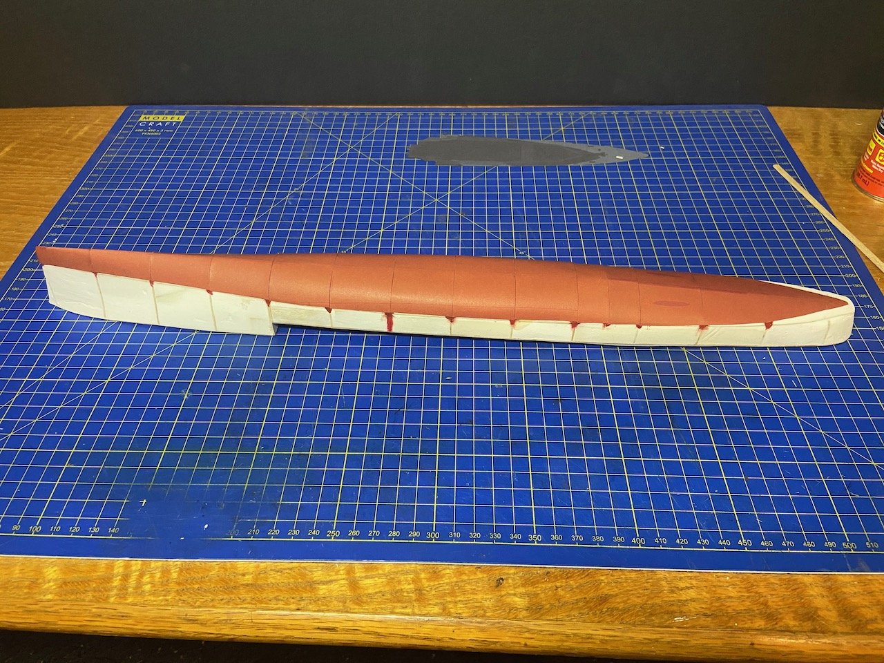
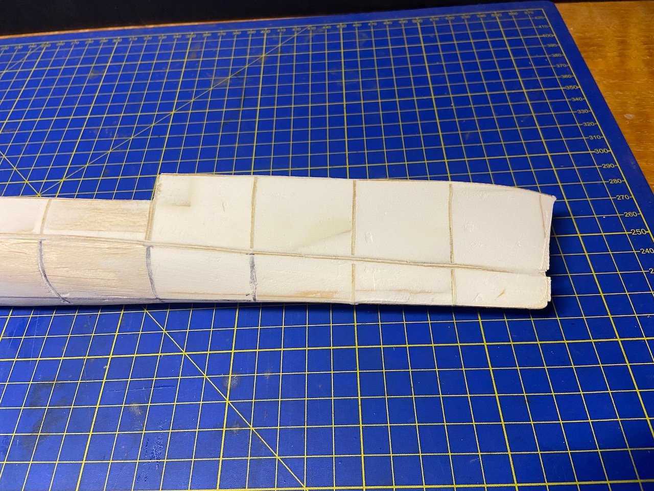
Over the weekend, I realized that first assembly had to wait until I get some of the details added to the underside of the hull. So, I worked on making the skeg and adding the bilge keels.
The skeg is provided as a folded over piece of card stock, with a hollow space inside. Figuring I'd damage that pretty quickly, I measured the hollow, a nice 1/16" wide space, and cut a piece of wood to fit inside. The only issue I ran into was getting the skeg assembly to fit flush against the hull. I had to do a little sanding, but I still had some thin gaps that would let light through if you backlit the model.
I didn't want to mess with the keg much more, so I just made sure to glue it securely in place on the hull. Then, I went back and took a tiny amount of the spackling compound I used to fill the hull, and I spread a tiny amount along the seams. Using a brush to press some of the material into any cracks, I then took a lightly dampened brush and cleaned up the surface.
Once, this had dried, I took a small amount of the acrylic paint I mixed earlier, thinned it well, and applied it along the seam. I then cleaned up any excess paint first by wiping with a piece of paper towel, then took a damp brush and blended any remaining excess, so it's no noticeable.
Note that I think using a damp brush on the hull of a paper model only worked, because the parts were "press" printed (what's the term I'm looking for here?) and not printed on my inkjet printer.
 \
\
What I did seemed to work pretty well. Also, the paint mix looks to be a pretty good match. It's actually a little dark, but I serves doubly as shading. I'm thinking that in the future, I may just fill any cracks between the lower hull plates with spackling compound and then just painting all the red areas.
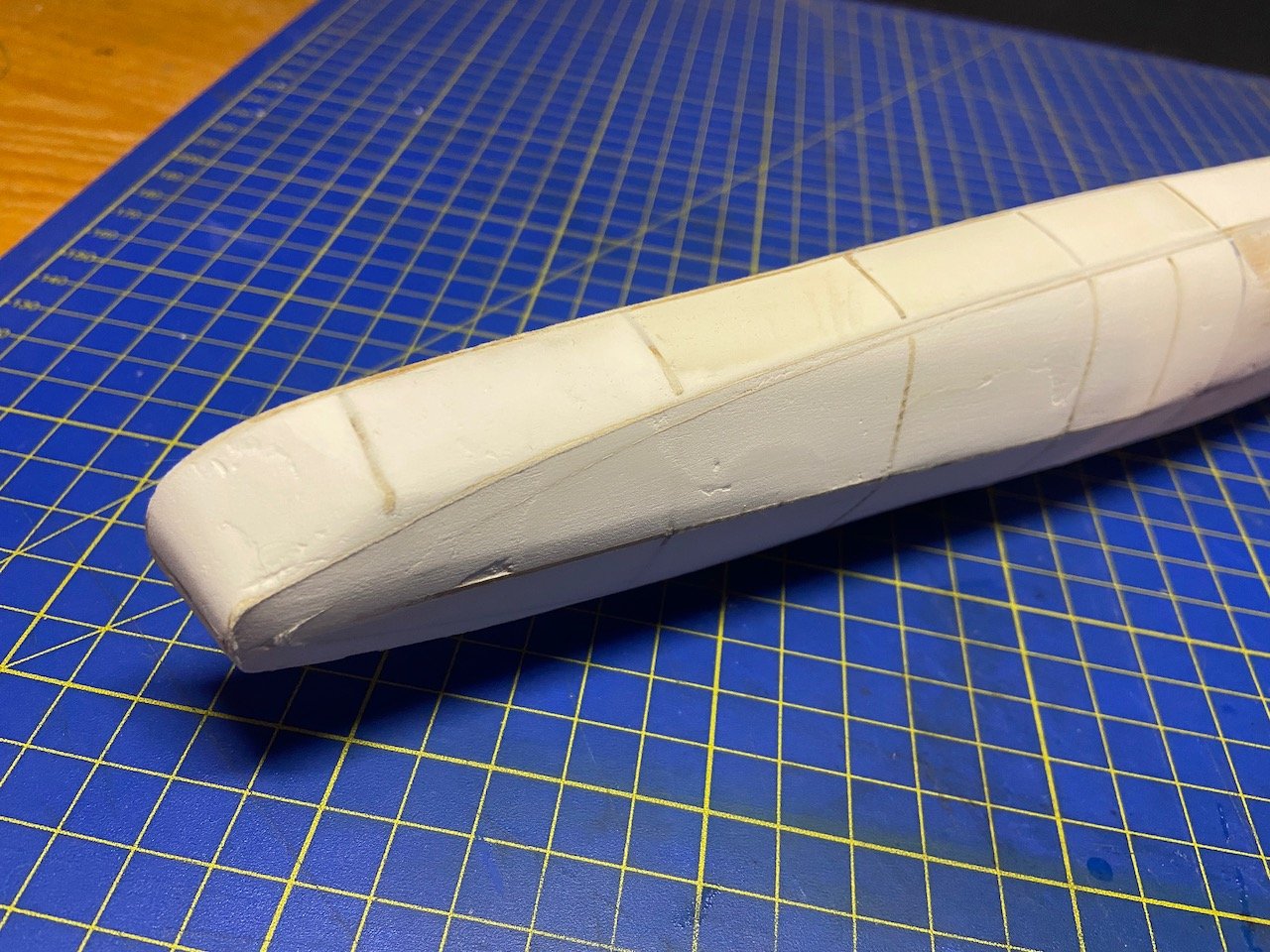
Next came the bilge keels. This wasn't difficult, especially given how well the gluing and painting worked on the skeg. For these, I glued them into place using Aleene's Tacky Glue, just like with most of the other paper parts on this model, but by the time I positioned the keel, it kind of dried out. So, I ended up applying a dilute coat of glue along the connecting seam. The glue dries clear, and you really can't see any residue after wiping the excess.
To be honest, I don't even recall if I applied paint like I did with the skeg. I was kind of flying by the seat of my pants here. Mostly, my attention was on keeping the curvature of the bilge keels nice and smooth, as it was easy to introduce some wobbliness while trying to glue it into place.
It seemed a little odd to me that the keels rise up at the bow end so much, but I followed the fine, printed guide lines exactly. Being primarily a wooden sailing ship modeler, this is the first model I've ever built where I had to add bilge keels, so I'm just trusting Avangard on this.
You'll note in both pics, I've drilled out a couple mounting holes and inserted temporary brass pins. These allow me to set the model on the pedestals and to keep it from falling off them. Again, this is only temporary. I'll either mount the model directly on longer pins and into a display base, or I'll use the brass pedestals and replace these pins with mounting screws. That's not going to happen until the work on the underwater part of the hull is done.
For now, this is how I set the model up...
Next, I'm working on the shafts and screws...
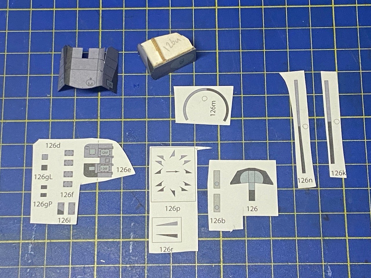
With the Avangard kits (I know nothing about any other kits yet), any rolled parts don't have any overlap. The rolled edges are glued, edge to edge. So, for these, I've used a paper shim to support the seam from the inside. You can see a little bit sticking out of the rolled part in the upper right corner.
Once the blades are glued in place, I will probably paint them and the hubs bronze. That's what I did with the V108, and I was happy enough with how that turned out.
Anyway, a little post-Christmas progress.
- king derelict, Canute, yvesvidal and 3 others
-
6
-
Merry Christmas, All!
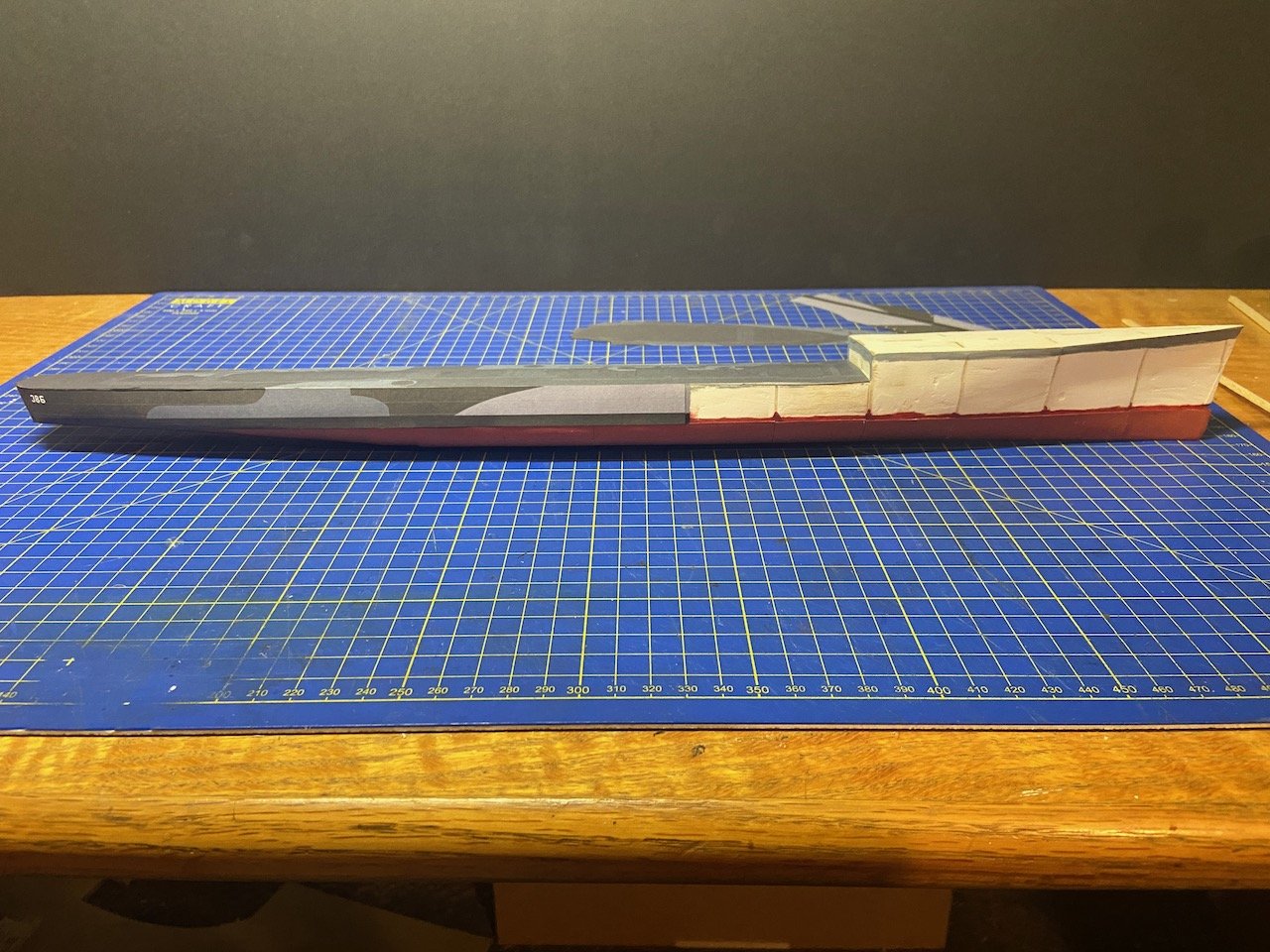
Not much to report today, but I started looking at how I'm going to mount the model, since I'm going to have to drill holes in the bottom before too long. I had some standard brass pedestals for ship models, the kind with the keel slot in them. Since the steel navy ships don't have an external keel, I went ahead and used a chop saw to carefully cut them down and ground and filed them clean, so the tops are flat.
Then, I realized that the bottom of the hull isn't THAT flat, so I went back and ground a very slight "V" into the pedestal tops. The proposed mounting of the model will then look like this:
The base is just one I have laying around. I actually think I prefer cherry wood. Also, I think I may opt for a 24" long base, which only extends about 1-1/4" beyond each end.
Meanwhile, I've gathered the parts for the first assembly, which I need to go on deck, just behind the forecastle. I'll need this in place before I can add the forecastle deck and the remaining hull coverings. But, I might need to deal with the underwater details first, while I can still freely turn the whole thing upside down.
- druxey, ccoyle, GrandpaPhil and 3 others
-
6
-
Oops! Thanks Johnny, Chris!
Your comments must have come in while I was sending my last post... 🤔
I appreciate the supportive comments. So far, things have turned out better than I thought they might.
Once the deck was mounted, there was a little overhang that I ended up carefully sanding away, but that seemed to work. It means that the deck is a tad narrower, 1/32" or so. I don't think this will cause any issues. There is only one assembly which spans the full width of the hull, and that's coming up in the next step or so. It's the rear bulkhead section of the forecastle, and I should be able to compensate during construction.
That assembly, by the way, was probably the most confusing part of the instructions. For the longest time, I had no idea what I was looking at or where it was supposed to go.
Now, it looks like I will be an interesting assembly to work on.
- ccoyle, sheepsail, king derelict and 2 others
-
5
-
Impressive work GrandpaPhil!
- GrandpaPhil, Canute and vvvjames
-
2
-
 1
1
-
-
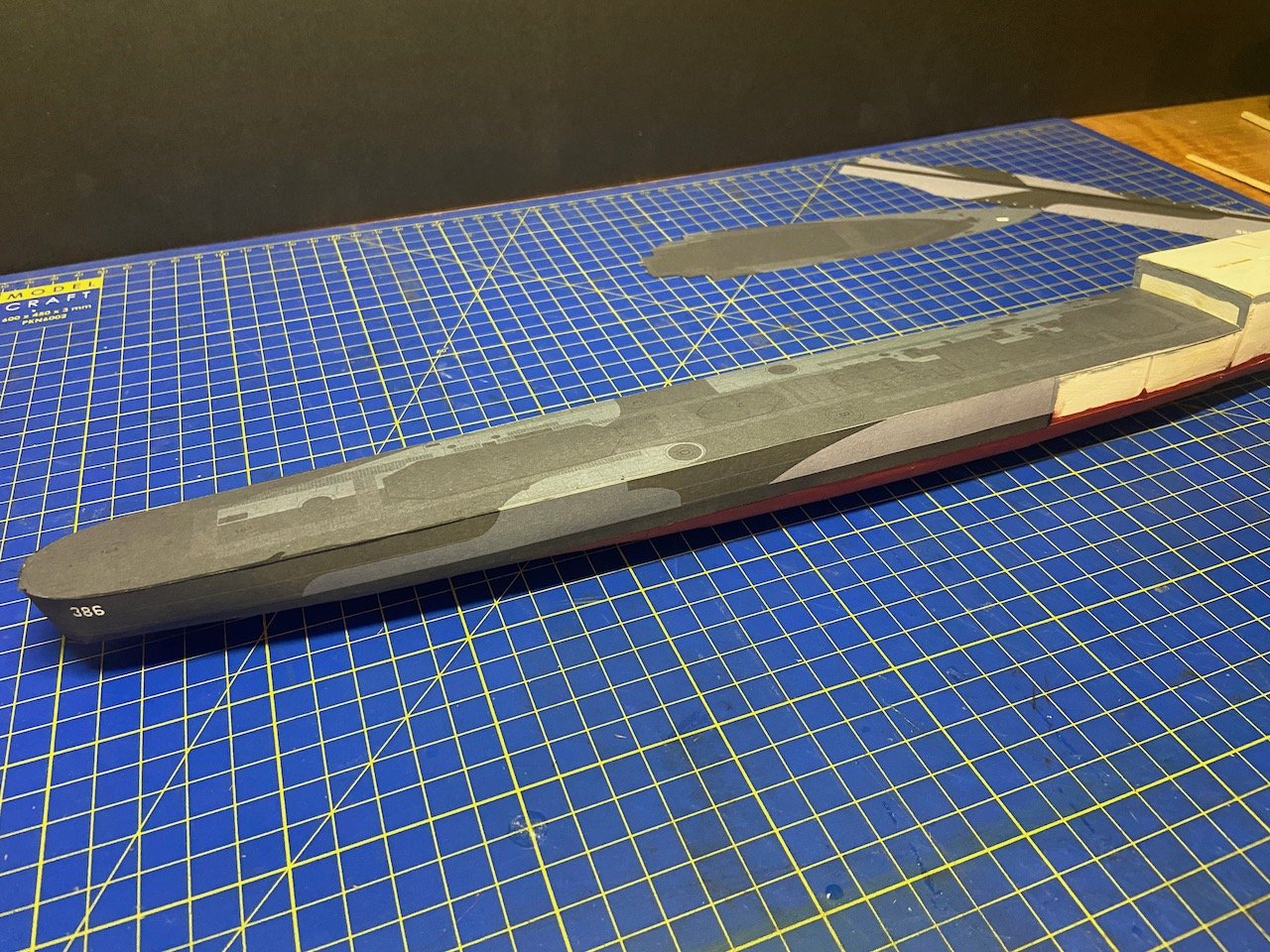
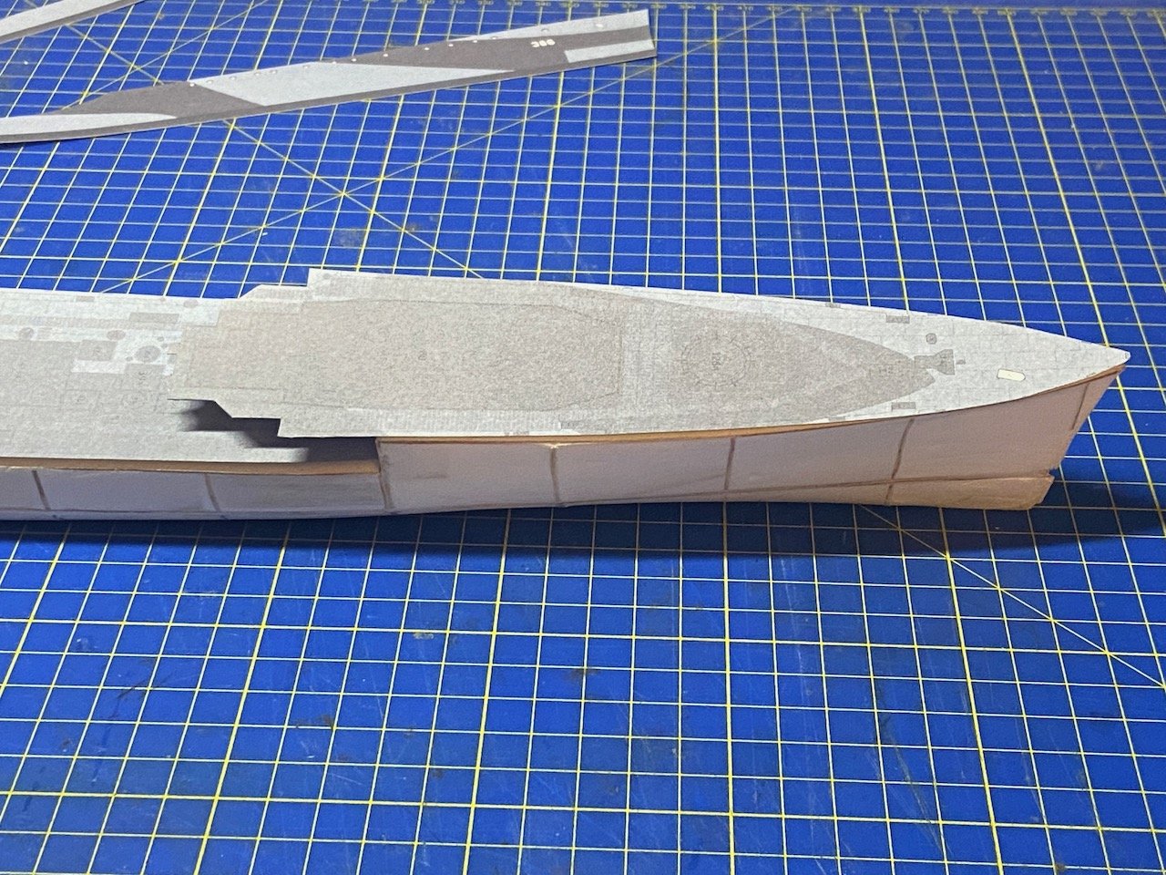
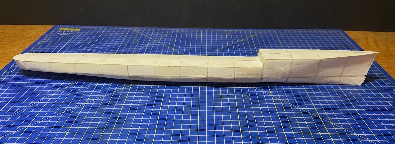
And pressing on a little more to make progress while I have some time before Christmas, I decided to add some of the hull parts.
The only ones I can do at this point are the parts of the aft deck and hull.
I can't add the forward hull skin until after I get the forecastle deck mounted. And, I can't add the forecastle deck yet because it overhangs the main deck, and I need to fit some details underneath the overhang.
Still not really being used to how paper models are supposed to handle curves, I'm not really sure if the underside of the hull at the stern looks okay. Not sure, but I think it does.
I test fit the forecastle deck and forward hull skins. I think everything should fit okay.
-
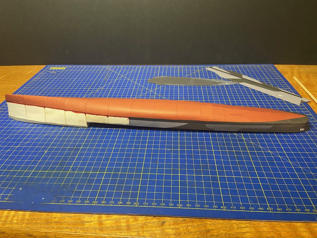
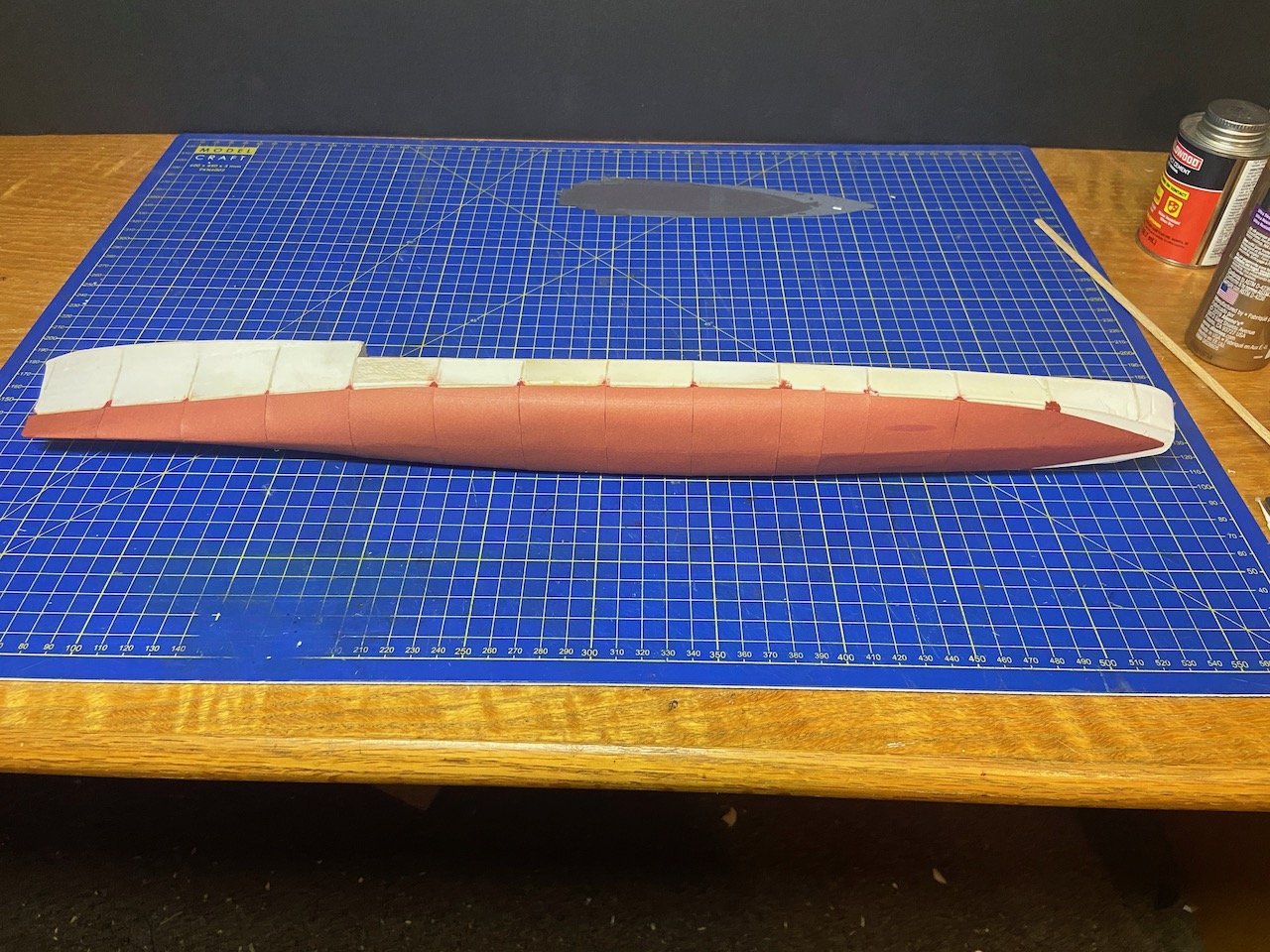
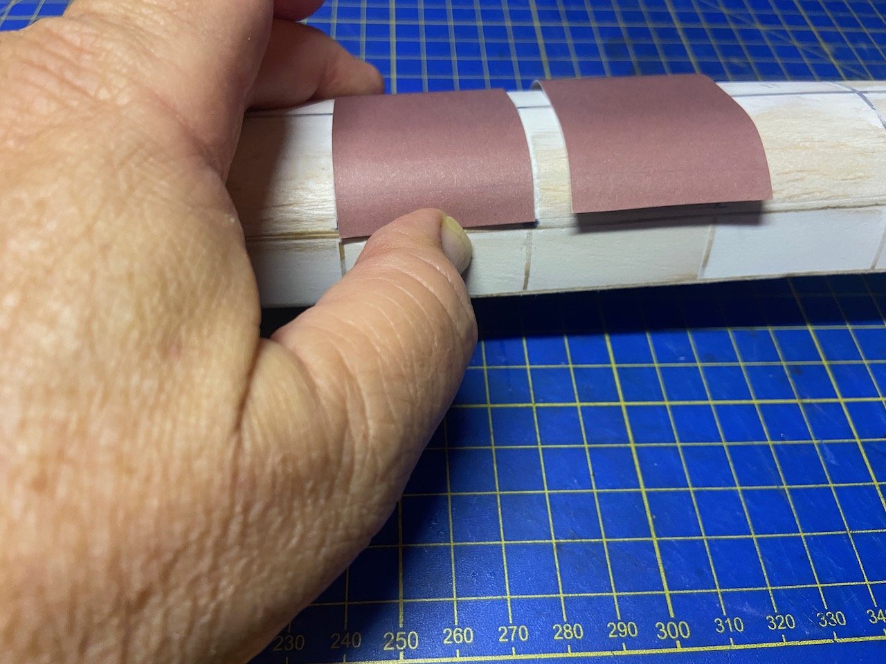
After staring at the hull for a few day, I decided to jump in and start the lower hull plating process.
Hmmm... not excited by the results, but then, I've got a lot to learn. This is just a step on a path.
After all the filling and sanding, I'm kind of wondering how much different things would have turned out if I hadn't done that. Well, certainly in the future, it will be easier to handle the model without accidentally caving in the hull.
However, in the process of sanding smooth the wood/filler, the hull may have narrowed a bit, meaning that the deck is now just a bit too narrow. Not sure how well this will work, considering the structure that has to fit across the deck, just under the forecastle. May need to do a little squeezing later...
I'll probably be able to adjust. I think I need the cover the sides of the upper hull to continue, though I have more that needs to go on the underside of the hull, including skeg, propeller shafts, screws, rudder, and bilge keels. I also will need to work out how the model will be mounted.
I went back over the steps on my V108 build, and I'm trying to follow the approximate build order.
-
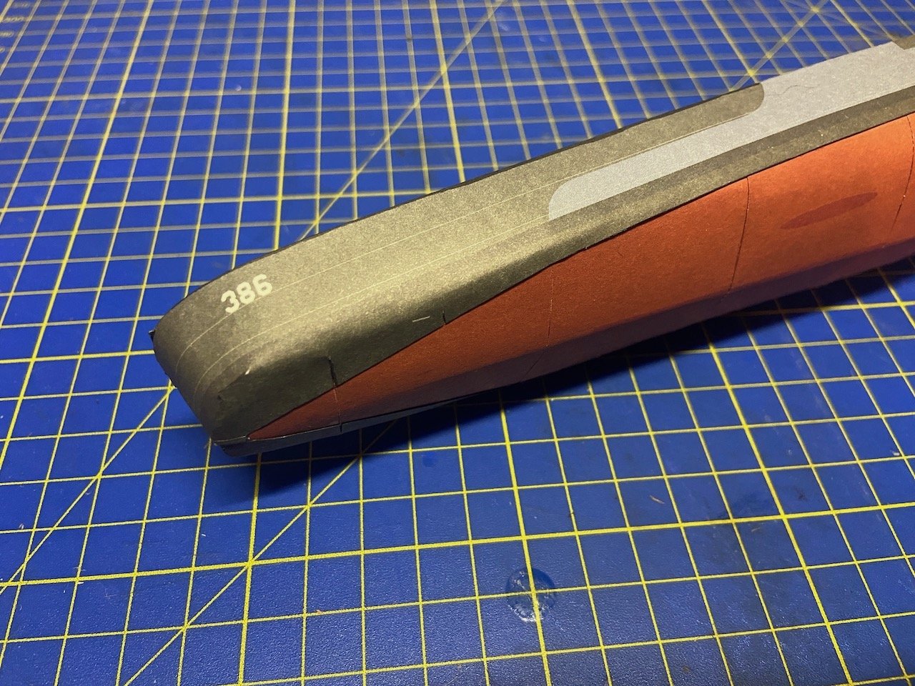
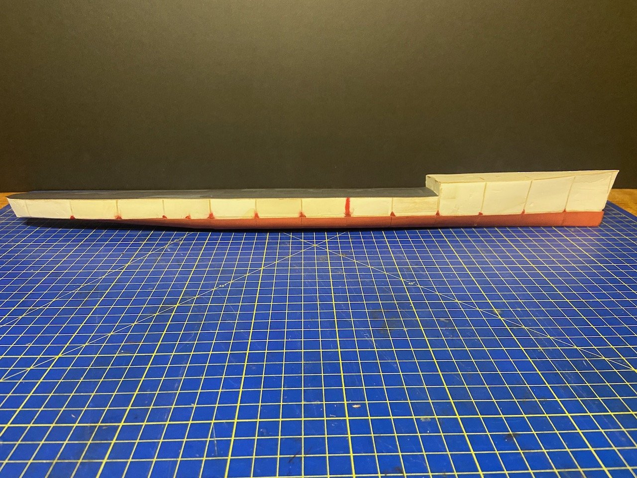
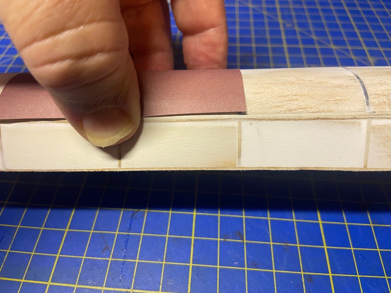
After staring at the model parts and contemplating the build, I finally moved forward a little. I decided to paint the edges of the hull plates, so I made up a red-brown mix, cut all the pieces, and painted the edges. I also decided to paint the seam areas of the hull, so if there is any gap between any plates, you won't see just white paper through the gap.
The painting made it easier to spot gaps in the filler, but also created some gaps where the filler was too thin, and when moistened with paint, just caved. This happened in a couple spots because I used wood blocks first, which didn't quite fill the space between bulkheads, and there wasn't much filler in the remaining gap. So, I went back and refilled spots, which is what you're seeing in the photo below.
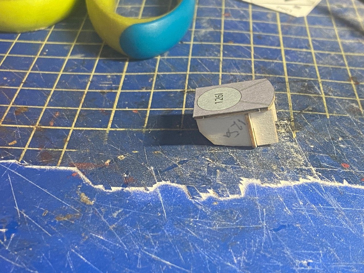
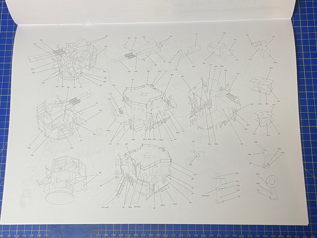
The, I finally got up the courage to add the first paper parts, but not to the hull yet. I figured I'd start with the 5"/38cal gun turrets, because if I screw those up or have too much trouble, I could always get some 3D printed ones, which I was considering for this kit anyway, particularly if things get a little too much with the twin 40mm or 20mm mounts. The enclosed gun turrets would be an interesting test, and should be fun to build.
So, I added the base pieces.
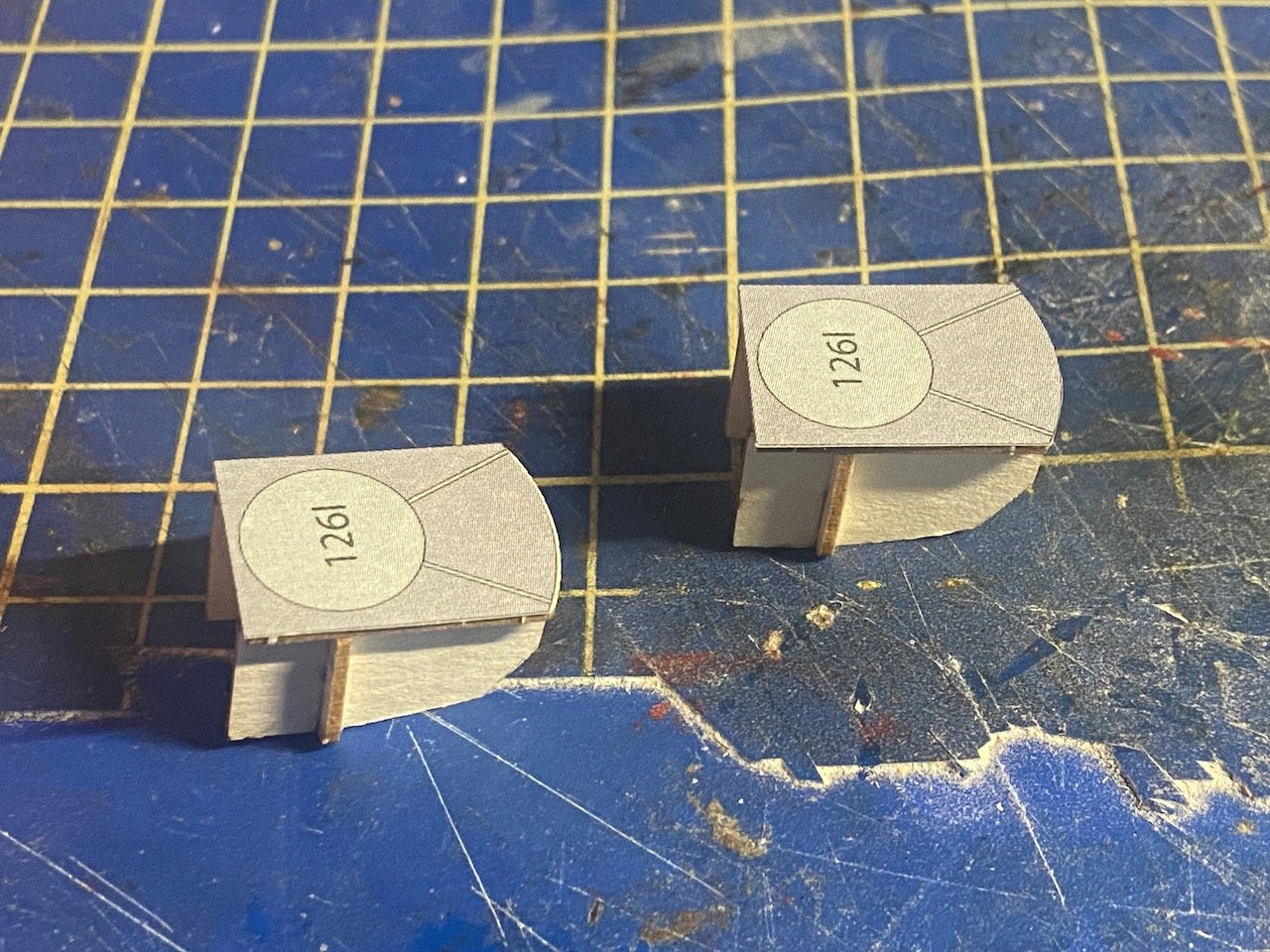
So far, so good...only to find my first screw up! The bases are backwards!
When assembling the laser-cut pieces for the turrets, I managed to get them on backwards... 😡
Took a bit of surgery with the scalpel and some careful handling, but I managed to correct the issue. I think I'll be okay now...
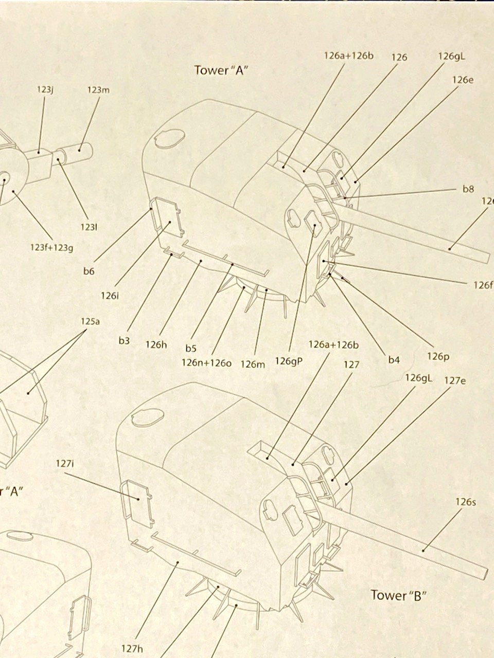
After that, I got a bit brave, but also very curious how the turrets were going to turn out. The assembly is complex, and I've studied the drawings. It took me quite some time to figure out where all the parts were going to go, or where to really begin, as I realized that some of the parts have to be put on before others.
Anyway, I figured a test fit would be safe...
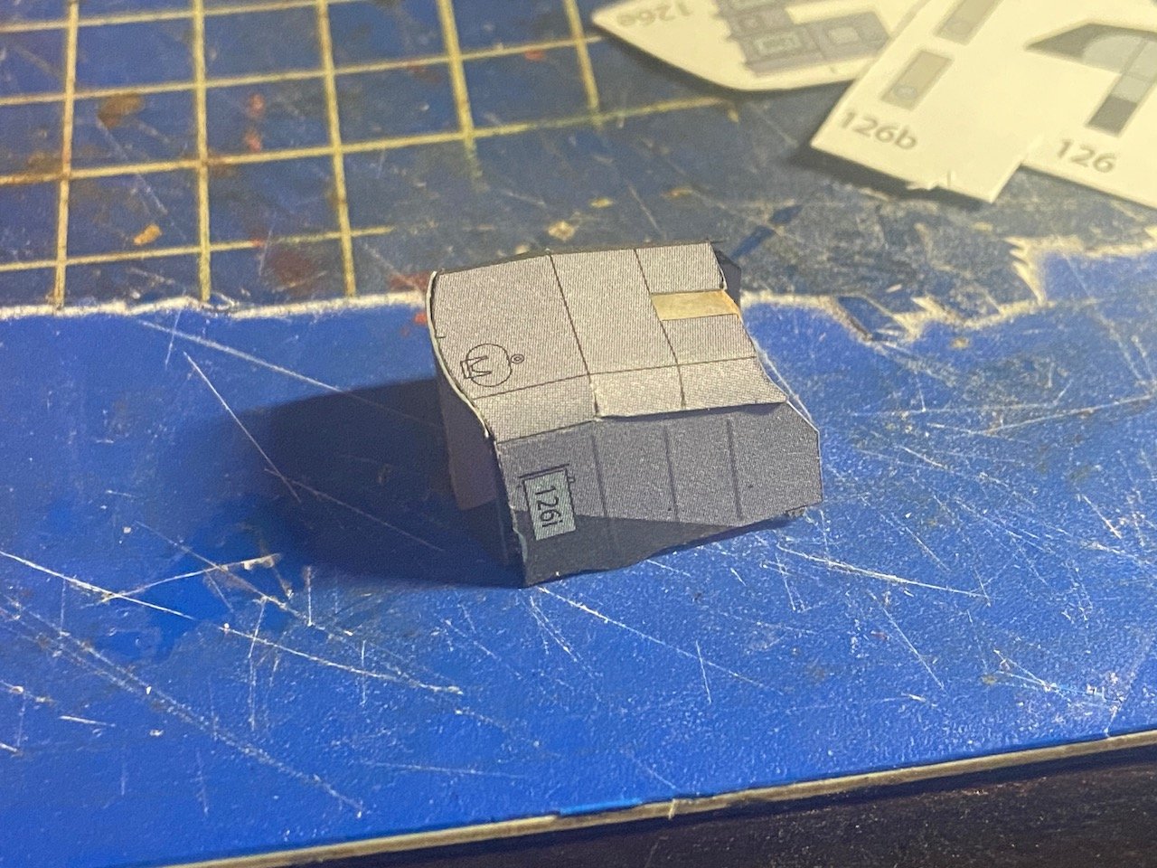 It was clear that the upper edges needed to be rounded, but getting this all to look clean is going to be a real challenge. I'm now recalling that exposed edges probably need to be hidden from a top view, so that back panel may be placed too high, and the turret top needs to mounted first... 🤔
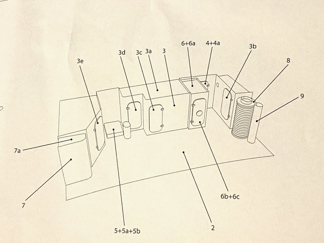
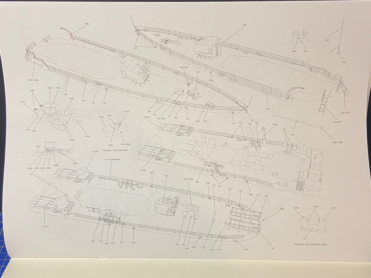
Here are the instructions in full:
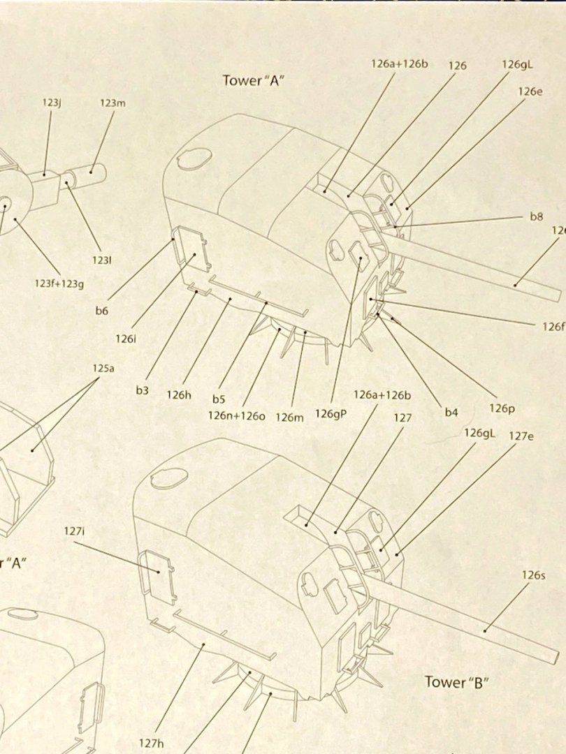
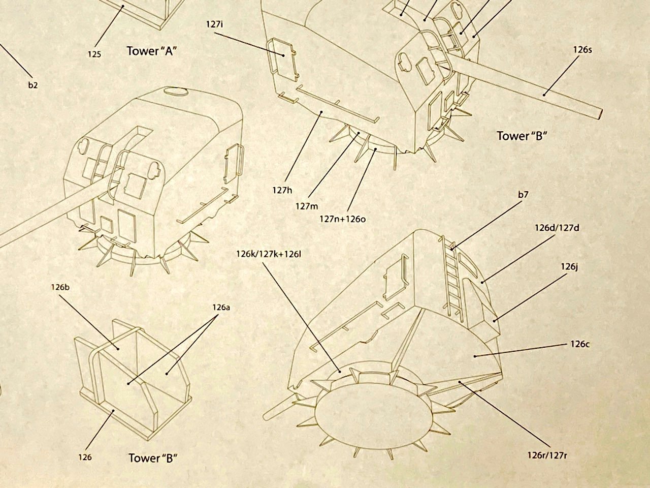
... And all the parts for the turret the kit calls Tower "A":
- druxey, GrandpaPhil, ccoyle and 2 others
-
5
-
Hi ddp, thanks for those links, the pics should prove very helpful!
Sorry for misspelling your screen name earlier. I realized today that it happened again because modern computing has apparently made things a little worse in many ways, including changing what I type because my computer think I misspelled something...😡
-
Julie, is there no end to the breadth and depth of your fascinating digressions??? 😀
I get what you're talking about, am somewhat familiar with about half of it, and completely understand maybe a quarter of it. But, it's always interesting, none the less!
I also have been thinking about the Saginaw again, now that our ship modeling group is maturing (not just in terms of age of the members). I feel our group's local connections growing, including Mare Island connections, and I'm trying to stave off a sudden strong interest in modeling the 1891 monitor USS Monterey, after seeing the photo on the recent cover of the National Maritime Historic Park Association's Sea Letter magazine!
-
10 hours ago, Snug Harbor Johnny said:
This gives me an idea ... since the hull below the waterline has the most 3-D shaping the paper has to conform to, on a completely filled hull like catopower's, one could forgo papering that area (least seen anyway) - simply seal and paint the color of antifouling paint (typically a rust red). From the waterline up the paper would be used (excepting some features like optional metal gun barrels and metal railings). Most stuff topside come in flat planes or simple curves (there are some exceptions) .. so once past the underbelly, Bob's your Uncle !
Hi Snug, was thinking about that possibility. I've seen some paper models where the lower hull seems to be devoid of seams, and I'm wondering if they did just as you mentioned.
In my case, at least for this build, I think I'll stick with the kit's hull plates, with the filler providing the backing support.
-
-
Hi Chris, yes, that's what I was expecting, plates that butt up against one another, like they did with my V108 build.
I prefer a full-hull model myself, except if I'm maybe doing a waterline diorama, which I have to try sometime.
Anyway, I'm using the original kit parts now, and it looks like they'll work as expected. I'm now looking at either ordering paint markers for edging the red underwater hull, or I'll end up going back to what I originally did with the V108, which was to just carefully use paint.
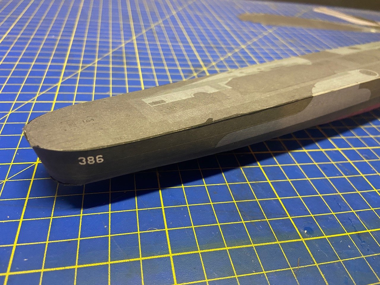
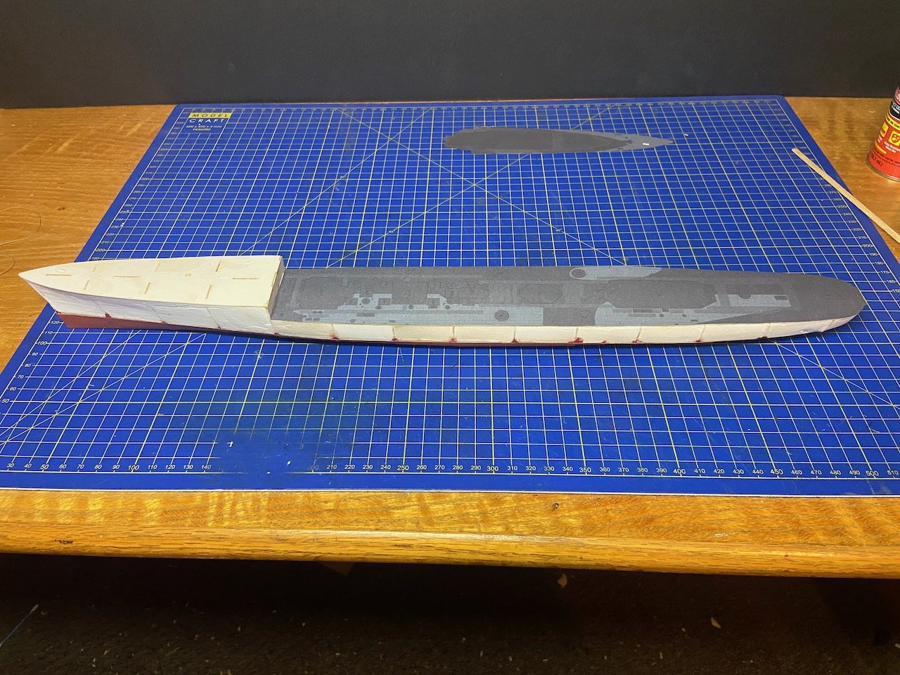
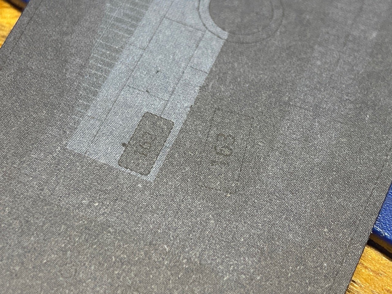
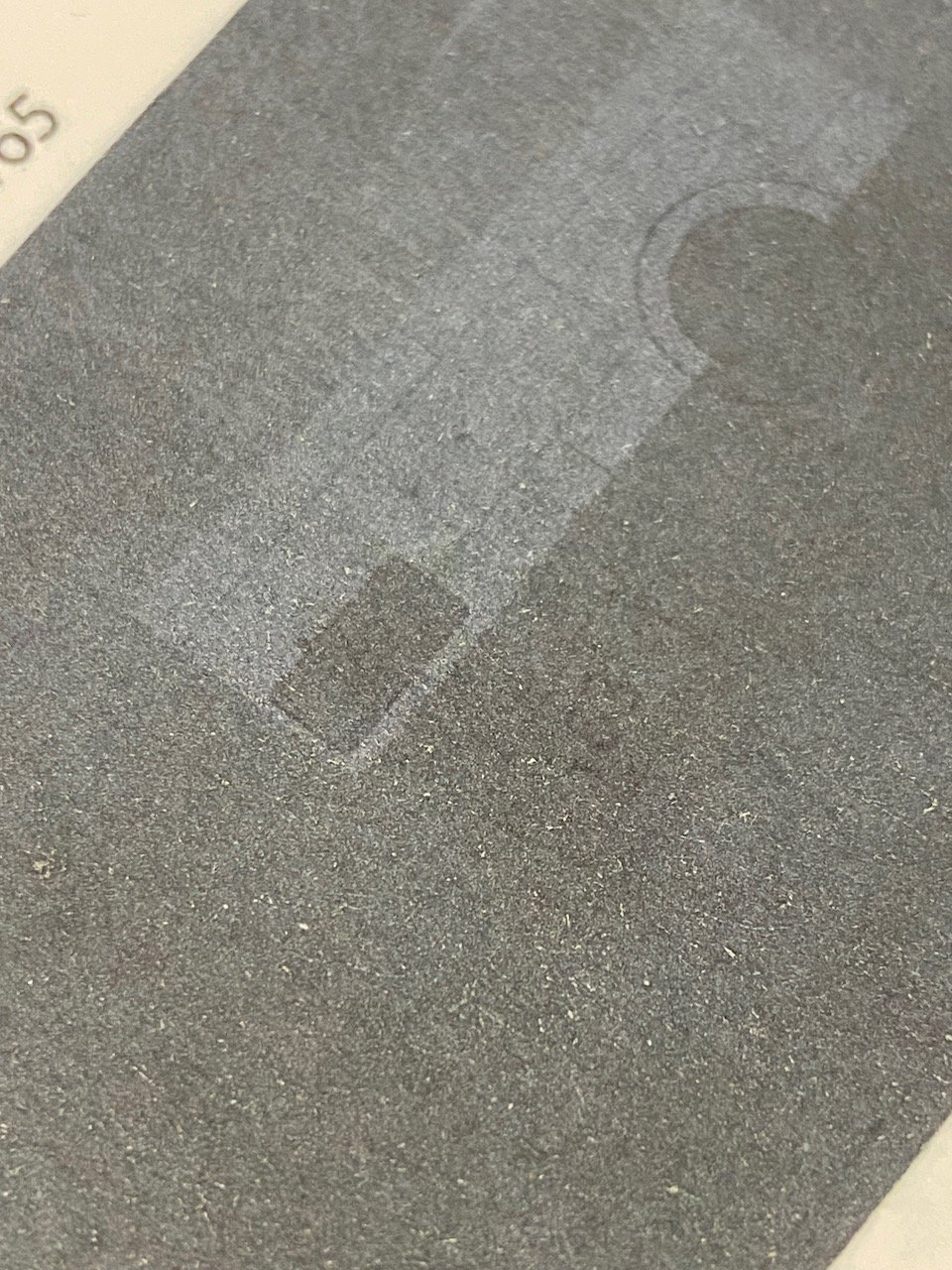
Big advantage of using the original parts is that there's no color distortion or detail loss that comes from scanning and then re-printing. As I mentioned before, the colors on the deck in particular are a bit muddy, and with the light shining just right, I can just read the number labels on the deck. That's not possible with the scanned and reprinted parts.
Here's the kit part...
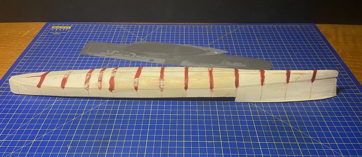
And, here's the scanned and re-printed version...

Honestly, even with the kit part, the numbers are so hard to see that I didn't even know there were any. However, I'll make it work.
Anyway, I found the company had posted a jpeg on their Facebook page of this same parts sheet these came from, and the writing on it is nice and clear. And, yes, I thought about using that file, but it's only the one page, and I've had enough issues with sizing and color adjusting the printed output. So, I'm making due now with building the kit as it comes...
- king derelict, GrandpaPhil, Canute and 3 others
-
6
-
A bit of an update here.
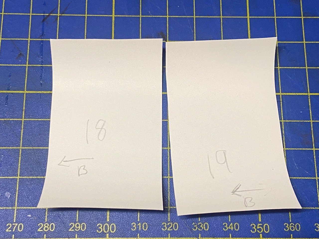
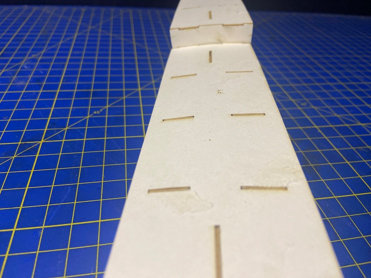
So, I took one of my early printed parts sheets to use to test fit parts on this hull I'm making (Printed parts sheets started as a scan of the kit parts pages, which I then printed out on my own printer). This turned out to be a very useful test, and gave me more confidence going forward.
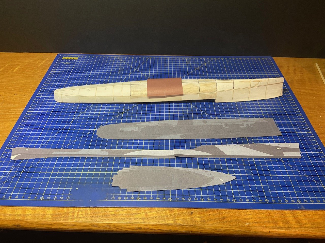
The most important thing this showed me, was first, to make sure to write the part number number on the back side of the part, AND to indicate which way the part is supposed to go on. In this case, I simply added an arrow to show the direction of the ship's bow.
The next thing I discovered is that these hull "plates" extend over each the bulkheads. This means in order to use them, I'll have to trim them down or to overlap them. Neither solution seems ideal.
Then, I got to thinking... I checked these pieces against the original parts sheets – I could do that now, since I had these parts cut out and could easily lay them on top of the originals. Sure enough, my printed parts are slightly oversized!
Now, I could try to figure out what percentage I would need to reprint these at... Or, I could just use the original kit parts, and maybe see about getting a second kit in case I mess up a part, a strong possibility. I could also just figure on reprinting a parts sheet when and if I actually end up needing it. I suppose I could also hold off purchasing a spare kit until I actually need it. Then again, I don't know if that will be possible when the time comes, so I might just look into it now.
- yvesvidal, GrandpaPhil, druxey and 2 others
-
5
-
Snug Harbor Johnny,
on digital downloads, I thought about asking Avangard about the possibility. It would certainly bypass any printing issues they have, cause by them being forced to use a less desirable paper. But, I really wanted the laser-cut frames and details sets, so I needed to place a physical product order anyway.
I scanned their kit pages and did do some color adjustments, but only using the Preview app that comes native on Macs. The result is okay, but not as good as it would be if I could get the digital files from them. For now, I'm just going to use the product that they sell. If I do have any problems with it, it's likely going to be due to my inexperience/mistakes rather than their product.
- Canute, druxey, GrandpaPhil and 1 other
-
4
-
6 hours ago, ccoyle said:
I'm really keen to see how this turns out.
Me too!
I don't know if I'd do it again. It makes the hull pretty heavy. I've seen other using carved styrofoam or insulating foam, which I might try out in the future. I do however like to use wood reinforcement in specific areas, particularly where I expect to add mounting pins or screws. I did that with the V108, and I think it helped a lot when I went to mount it using brass rods. But, in that case, I'd used small basswood blocks, and they don't extend out to the surface of the hull, but are just for internal support.
Chris, Johnny, I see what you're saying about perfectly filling out the hull. I was just never concerned with anything other than avoiding the distended ribcage look, and I don't think that'll be a problem now. The gaps I'm talking about in my hull, I don't expect to be a problem. But, perhaps you're right. I'll go over it one more time to get rid of what are kind of like 'nicks' in the spackle.
My main concern now is that I've done a lot of sanding, and I'm concerned that this inner core of the ship will have shrunk too much. I was considering taking one of the reject sheets I printed out to test fit a few of the main hull parts to see if I've messed anything up yet.
Also, the stern on this model is a bit funky. The aft most frame kind of hangs out, and I have no way to judge how the paper is supposed to create the proper curve without trying it out. This also affects the shape of the filler, which at this point, is shaped based on a "best guess".
- ccoyle, king derelict, GrandpaPhil and 3 others
-
6
-
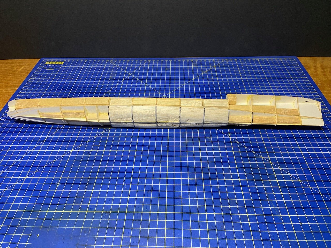
Good news, I don't think I've ruined my model yet!
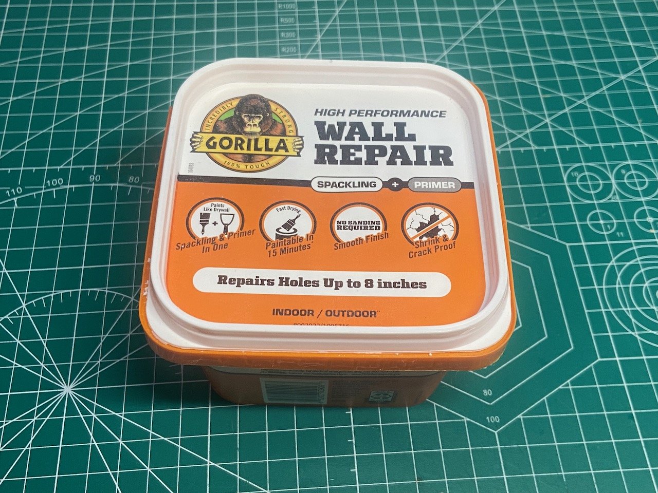
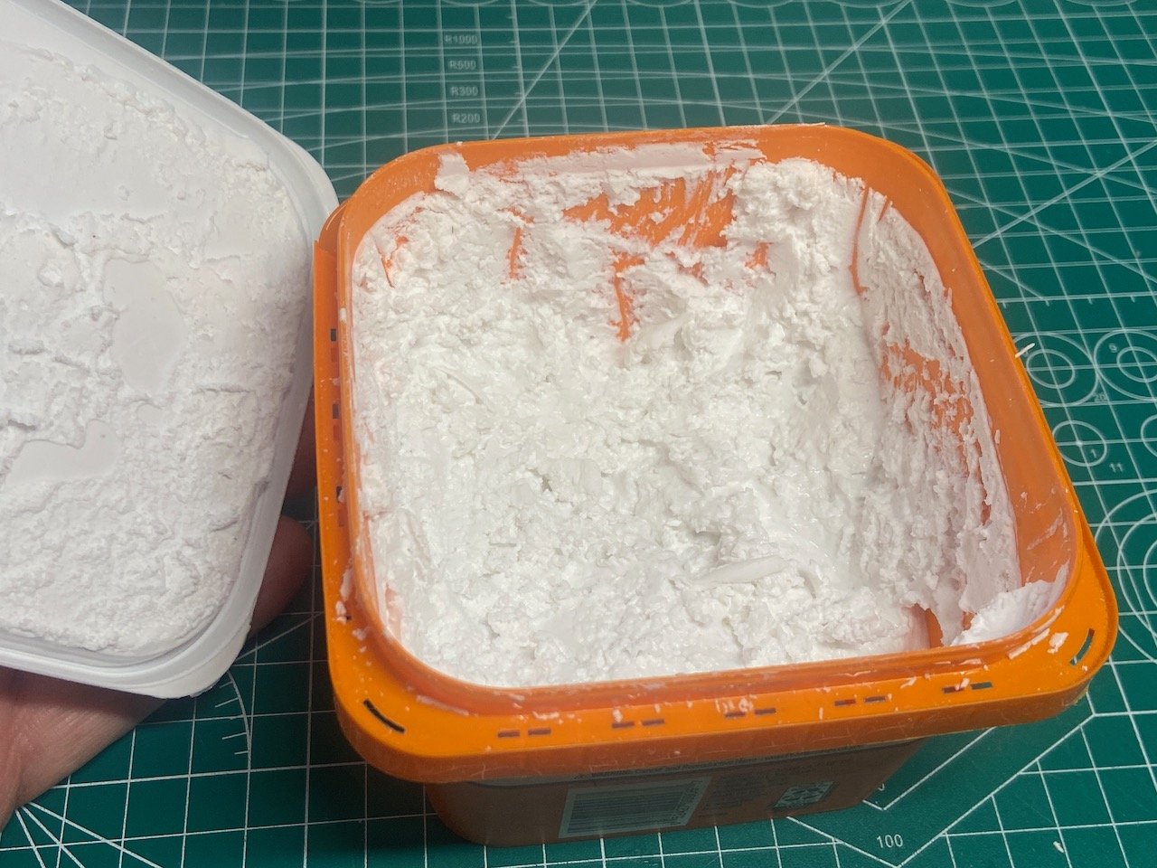
I ended up using Gorilla brand wall repair spackling. The stuff is fairly soft and kind of fluffy going on, or 'in' as with the case of the framework of the paper model.
Doesn't look very good right after applying the stuff...
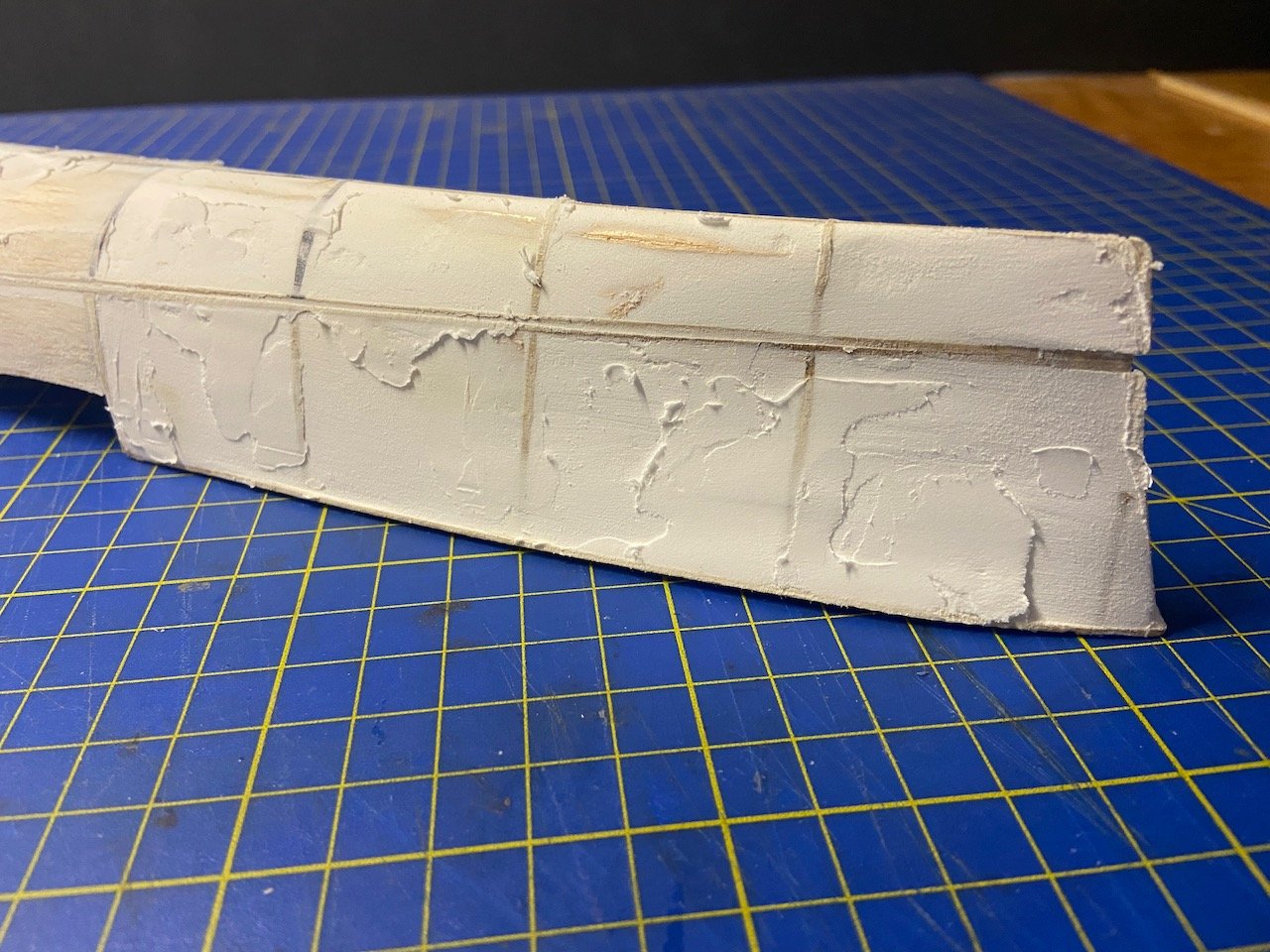
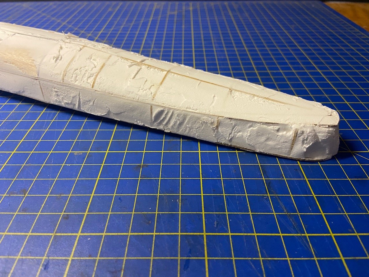
But, once dried, it was easy to sand it smooth, though I ended up having to re-apply it in a few spots. Eventually, got it as good as I think it needs to be.
There are still a couple gaps, but that really doesn't matter. The filler is mostly to give the hull more strength, and to provide even out the framing, so that the exterior hull pieces will lay nicely. A few small gaps won't make a difference.
I did notice that the deck had a slight bulging in areas. Probably, when I pushed the spackling into the framing, the pressure caused a little unevenness in the deck in a few spots. The result was also that there might have been a very slight apparent twist int the hull.
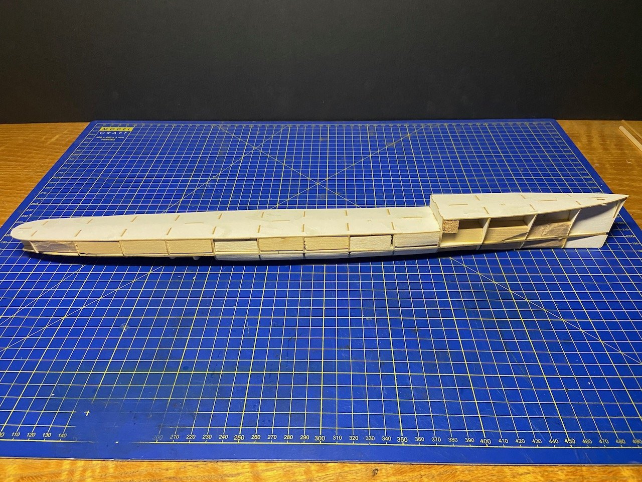
I found I could actually sand the heavy cardstock deck, leveling out the bulges pretty well. I was surprised at how well the card took the sanding.
Next step will be to start adding the hull pieces, starting with the lower hull.
I already went back and re-printed my scanned parts one more time, this time in "normal" output quality (according to my computer's printer settings), rather than in "best" output quality. The result was print that wasn't quite so dark, and the gray part were slightly bluer, and maybe a little less muddy. Finally, I sprayed the printed sheets with some Winsor & Newton matte varnish to help seal the paper and to protect the ink. I don't know that it really needs it, but I've followed a number of paper model builds where something similar was used.
No photos of this step, but I'll take more when I start adding the lower hull coverings.
- Ryland Craze, druxey, king derelict and 3 others
-
6
-
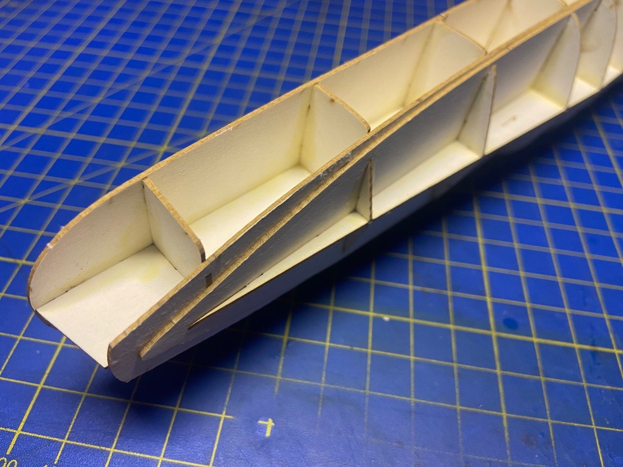
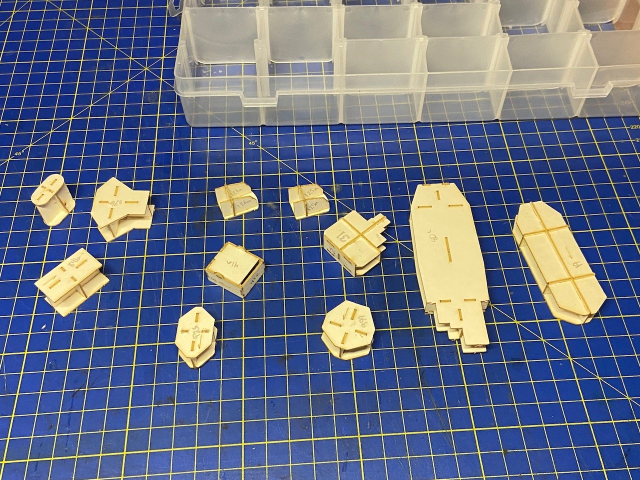
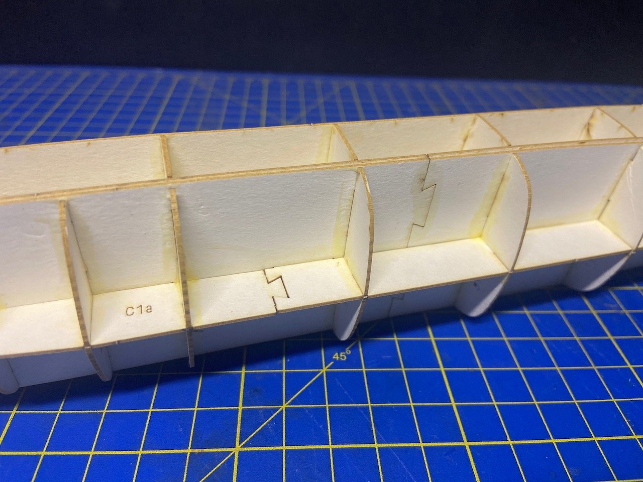
So far, I've really enjoyed doing the easy part. Started making the structures for the subassemblies using the laser-cut frames set.
Since most of the part labels were next to the parts themselves, I made sure to write the numbers on the faces of the parts, so I wouldn't screw things up... or at least reduce the chances of me screwing things up. I'm sure I can still do it...
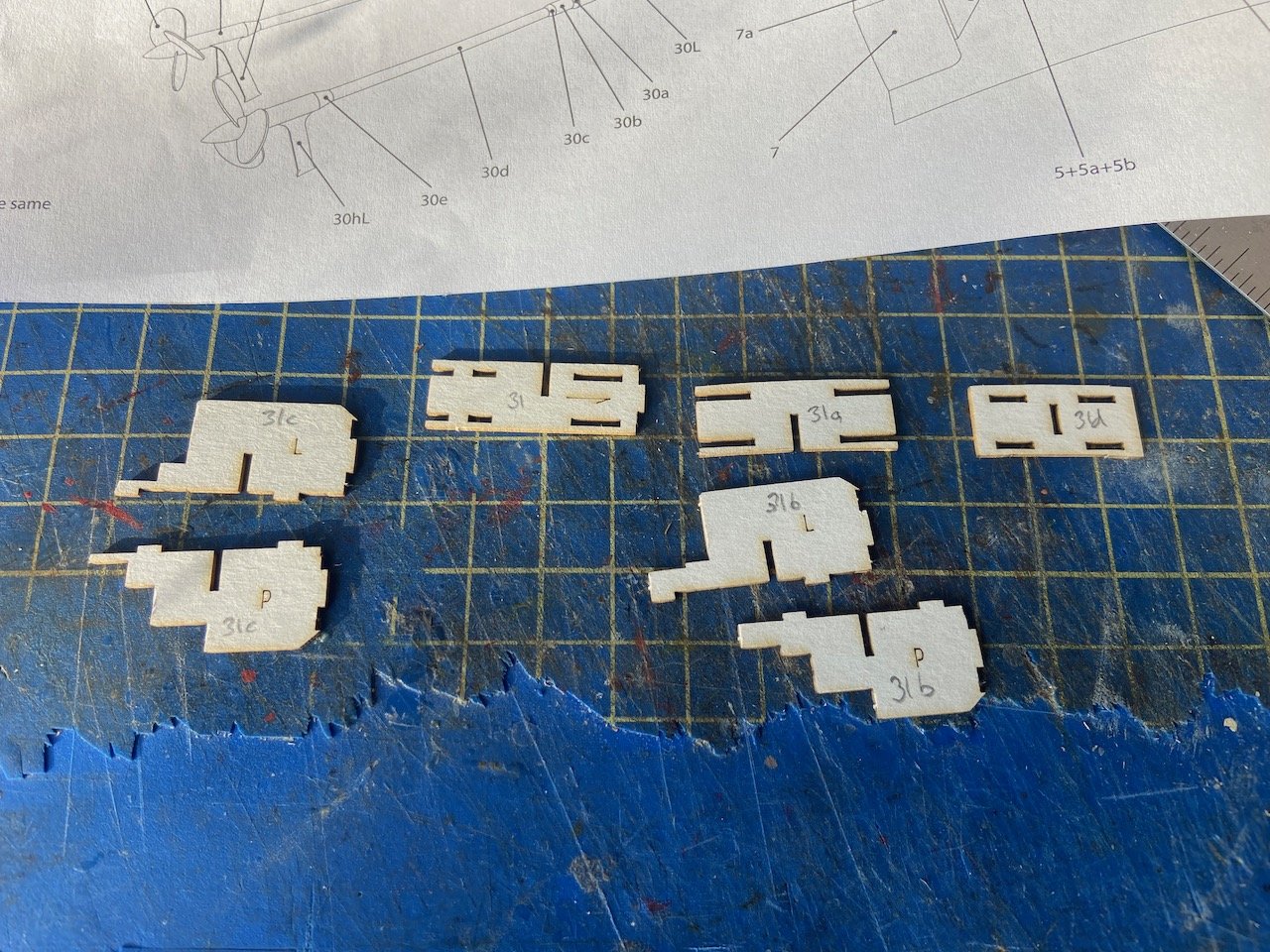
And, here are the substructure of many of the subassemblies.
Meanwhile, I added some wooden blocks to help stiffen the hull framing. The larger filer blocks are balsa, but I started running out, so I just reinforced sections with some basswood pieces. This should also help to support mounting rods at a later stage. That's what I've done with other paper models, though they mostly been a lot smaller than this one.
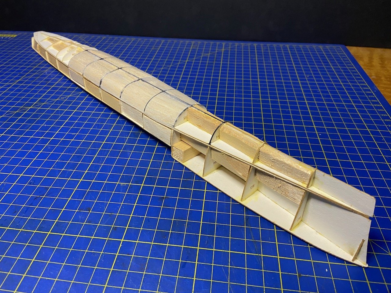
I'm going to experiment with using some filler to fill and smooth out the hull shape. I've seen some models where the builder used styrofoam instead of the wood blocks or filler. Just never been keen working with that stuff.
Worst case with my model hull, I'll ruin it and I'll need another laser-cut frame set. Anyway, I'm considering getting a second kit, because I know I'm going to lose or mess up parts. I've scanned and printed the parts sheets, but the color is off from the original, and the color and part numbers printed on the deck pieces are pretty muddy in the original and hard to read, and even worse in the printed scan.
- ccoyle, GrandpaPhil, yvesvidal and 3 others
-
6
-
Thanks Chris, I think that's basically what the Avangard instructions are showing. What's a little confusing is that it's hard to tell the placement of the assemblies. There's no master diagram that shows all the structures in place (with numbers), and It's difficult to see any numbers on the printed decks, but I can tell they're there.
I'm sure I'll figure it out, but it's a bit confusing at first. I guess that's one reason they call this an "advanced" kit...
- Canute, GrandpaPhil, druxey and 1 other
-
4
-
These steel navy ships in paper are interesting. I'm used to building sailing ships, but with these steel vessels, there seem to be a lot more sub-assemblies. Construction seems to be, at least looking at is all at this stage, less linear. For the most part, it seems I could work on the various superstructures off the model. Then, when they're all done, just glue them to the deck.
I have a lot to learn about these builds, and experienced builders clearly have developed techniques to make their models superior. I suppose that's true about any type of modeling. I'm clearly a newbie here, so I'll just learn what I can and do my best.
- Ryland Craze, king derelict, Canute and 1 other
-
4
-
Having just finished my first steel navy paper model, the German WWI torpedo boat V108, it seems appropriate to start a blog on this new paper model project, USS Bagley on Pearl Harbor Day.
I say appropriate, because the destroyer Bagley operated in the Pacific and was moored at Pearl Harbor on the day of the Japanese attack. Bagley's crew manned her .50cal machine guns and claimed to down a number of Japanese aircraft, though this couldn't be substantiated with all the anti-aircraft gunfire taking place. By mid-morning, she headed up the channel and out to the open sea under the command of a junior officer, as her captain, XO, and gunnery officer were still ashore at the time.
The ship was the lead ship of her class, built in 1937, as a "Treaty Era" destroyer, which limited her displacement to 1500 tons. She had an active wartime career and earned 12 battle stars. The ship survived the war and was decommissioned in 1946.
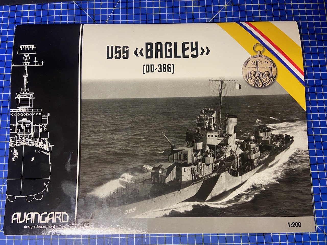
The Kit
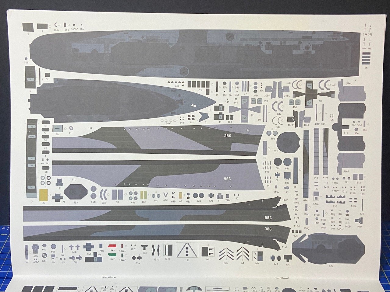
This kit is published by the Ukrainian company Avangard, and depicts the ship in her 1944 configuration, with camouflage. She was armed at this time with 4x 5"/38cal guns in single-gun turrets, 6x 20mm anti-aircraft mounts, a twin 40mm mount, 16x 21" torpedo tubes in four quad mounts, and 2x depth charge racks.
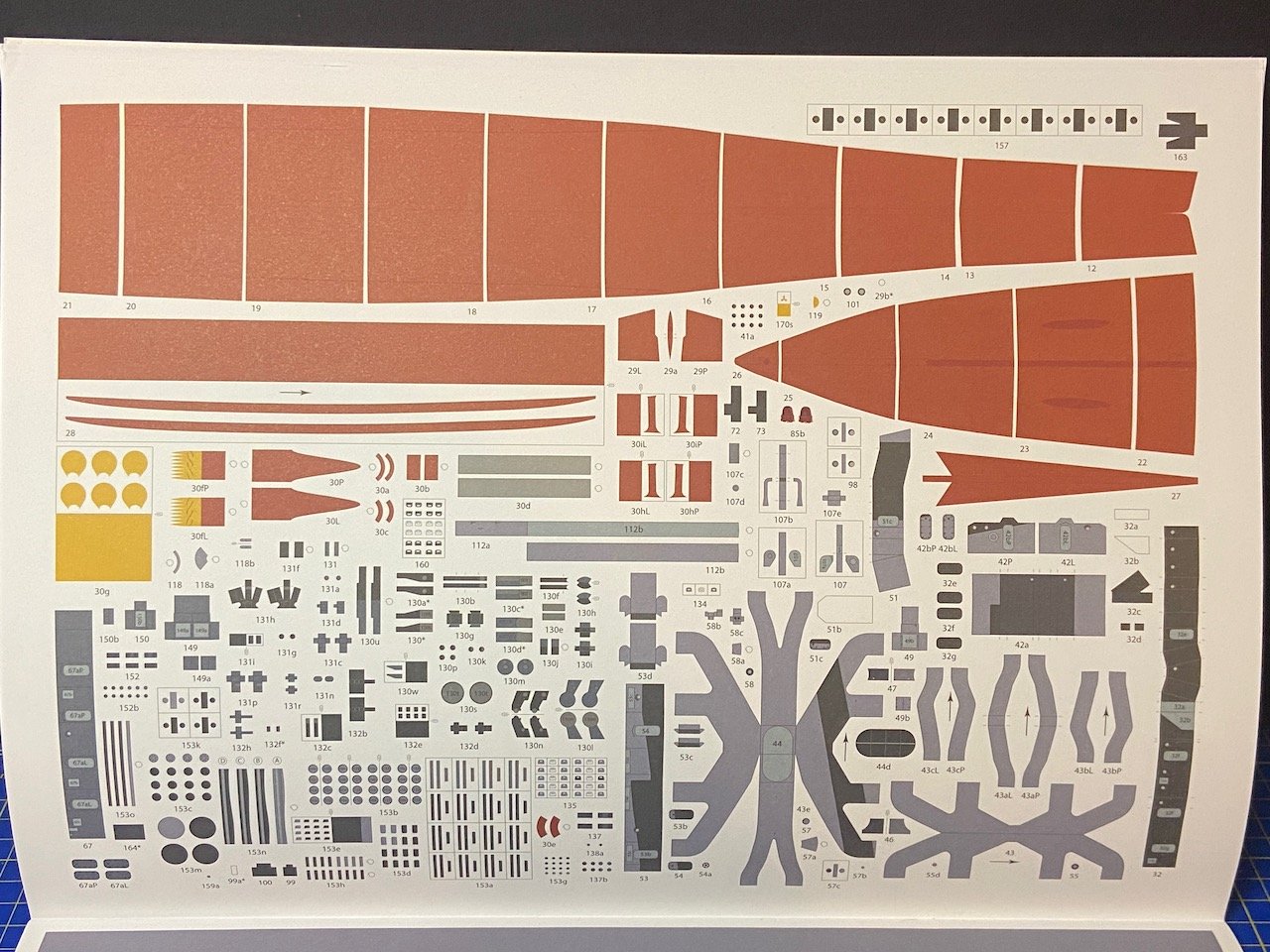
Some of the printing, particularly of the decks, seems to be a bit too dark, and it’s hard to distinguish some of the printed details. I suspect I might end up having a hard time placing some of the parts because of how dark things look. I contacted the publisher about this, as I didn’t know if this was normal. As it turns out, due to the war in Ukraine, the company has been limited on available paper supplies, and the paper they have been able to get doesn’t absorb the ink the way that they would like. This may be too much of an issue for some. But, I think I will be able to manage. It will help that there is a jpeg image of this sheet posted on the company’s Facebook page, with the printed part numbers appearing more clearly.
One thing that threw me, which had to be explained to me by someone at Avangard, is that there is one page that is clearly out of place. It’s a second page for the lower hull of a ship, but it’s different than the Bagley’s hull, and even has a label that says IJN Asashio. Apparently, this is not a mistake. There was a measurement error in the earlier Asashio kit, and there was extra space in the Bagley kit, so the publisher just stuck in the revised sheet. I’m just glad it wasn’t a error in my kit.
The kit has almost no text, except the ship history. But, what text there is, is in English. The drawings seem clear enough. Of course, only an actual build will determine if there are any construction issues with the kit.
Along with the basic kit, I ordered the laser-cut frames set as well as the details set, which is basically all of the railings, ladders, and other fine parts. All told, I think I spent less than $60 for the kit and accessories sets.
I had a very hard time purchasing this kit, but no fault of the publisher. Living in the US, I discovered that it’s almost impossible to get any paper model products from Europe. I tried to buy this kit from Fentens (Germany), GPM, and Orlik, but none would ship to the USA due to tariff and customs issues. I only got lucky when I contacted Avangard directly about my situation, and they were able to help me out on a one-time basis and get this kit and accessories sets to me directly. Many thanks to Avangard for their help!
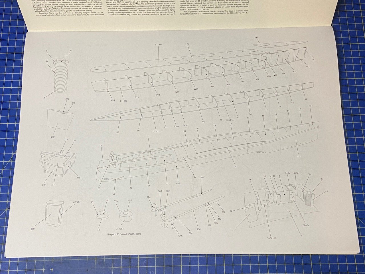
Instructions and Parts
I don't really have much experience with most paper models, except Shipyard kits, which are kind of their own animal I think the Avangard kits are pretty typical in terms of instructions and parts. There is no written instruction at all, only diagrams are provided. Interestingly enough, the only text is on the inside front cover and back cover, which are only written in English.
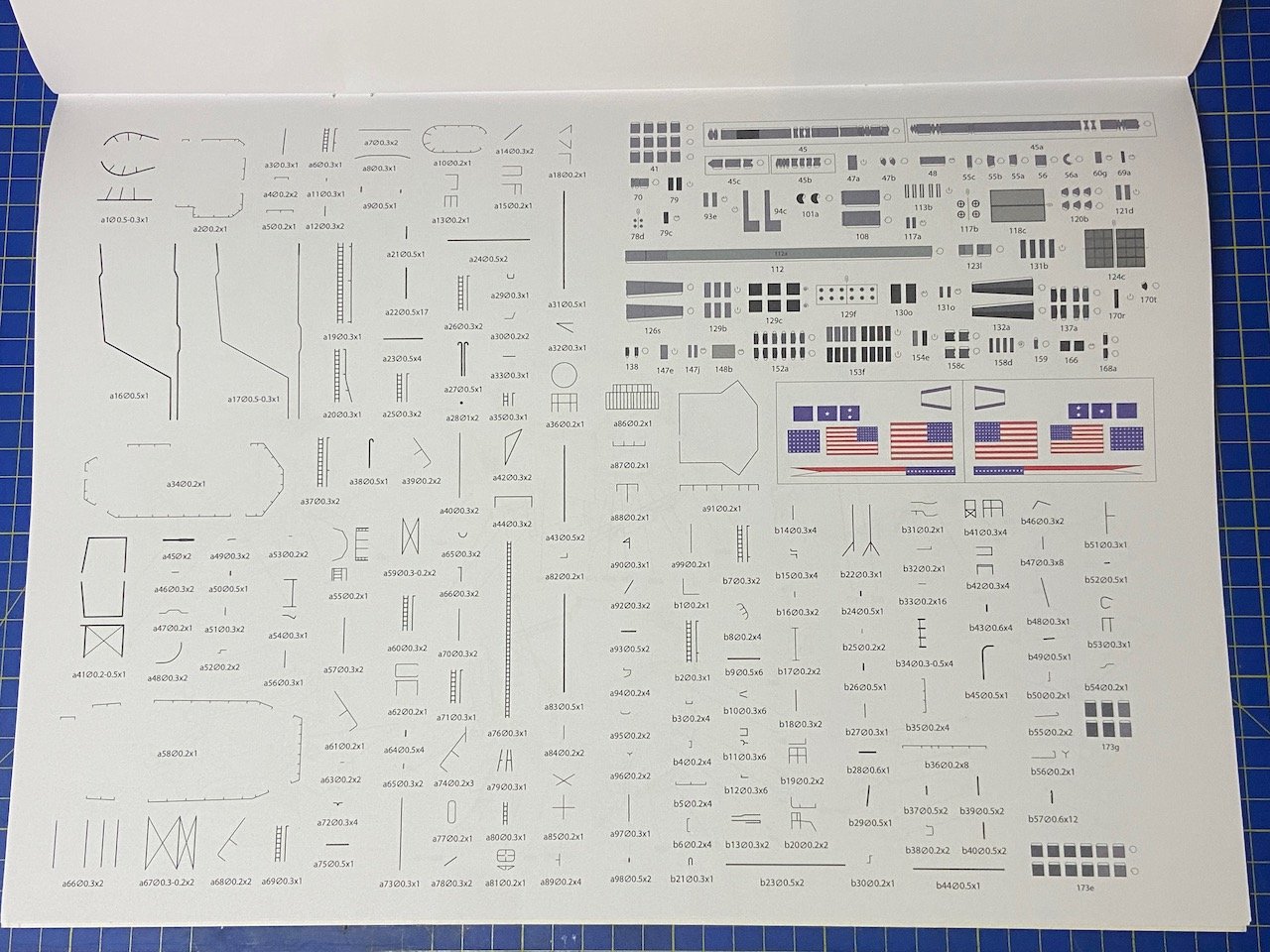
Building Begins...
The beginning stages of construction of paper models, seem pretty straight forward. These parts are from the laser-cut frames set. At 1/200 scale, this is a pretty good sized hull, just about 20-1/2" long.
I'm not sure if I did this the way I should have, gluing the upper and lower hulls together at this stage. But, it's all a learning process.
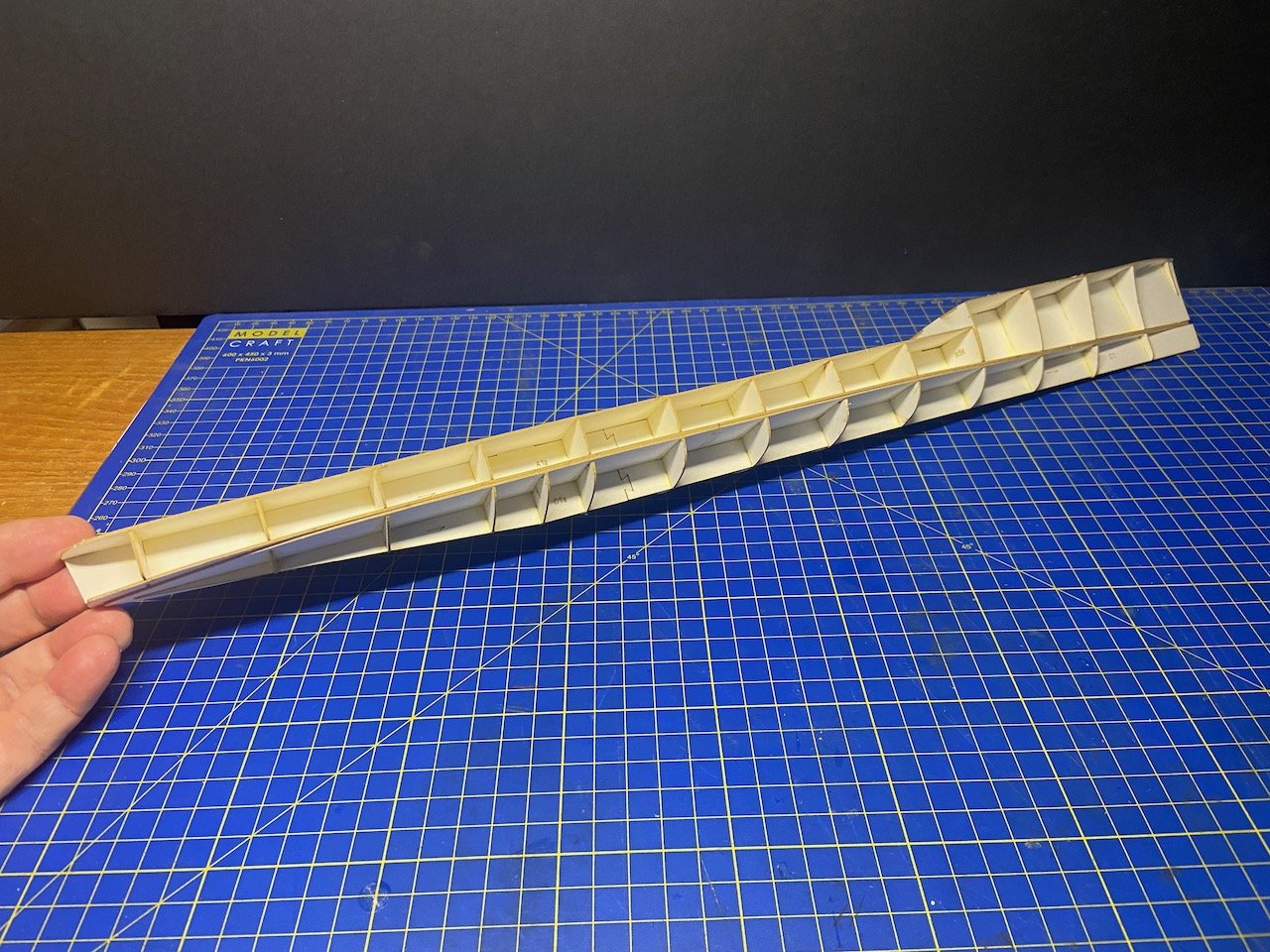
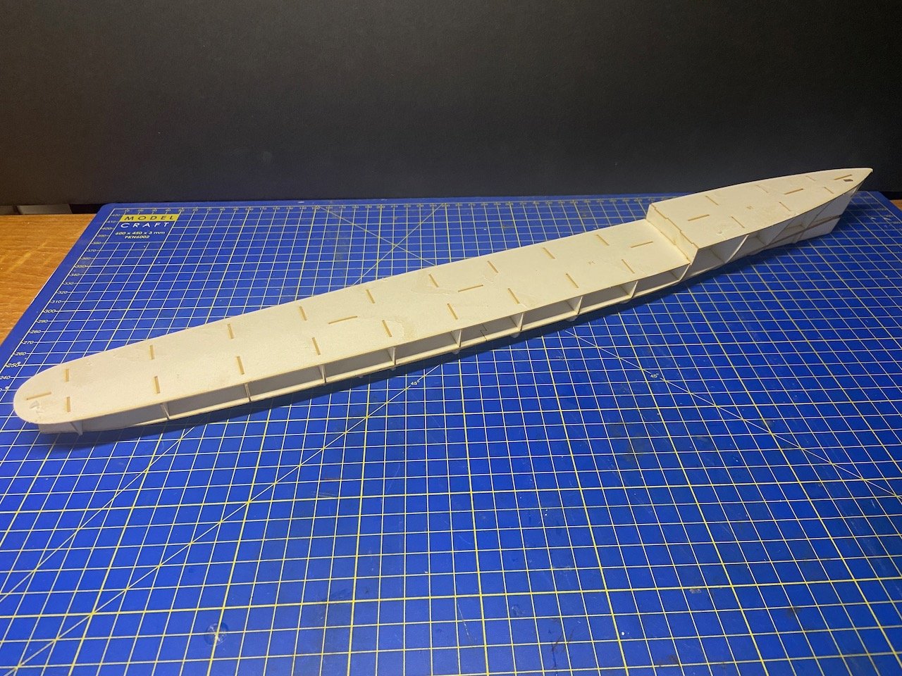

Don't know how much time I'll spend on this model, so it may be a slow build, but construction has begun...
- Ryland Craze, Canute, ccoyle and 4 others
-
7
USS Bagley (DD-386) by catopower - 1/200 - Avangard - CARD
in - Kit build logs for subjects built from 1901 - Present Day
Posted
Hi GrandpaPhil, actually, I found them more intimidating to think about than to actually make. Once I started making them, construction went along pretty quickly and easily. The things that are nerve wracking to me are little conical rings that make up the propeller shaft housings and all. The Bagley has three of these conical rings for each shaft. 😕