HOLIDAY DONATION DRIVE - SUPPORT MSW - DO YOUR PART TO KEEP THIS GREAT FORUM GOING! (89 donations so far out of 49,000 members - C'mon guys!)
×

catopower
-
Posts
1,897 -
Joined
-
Last visited
Content Type
Profiles
Forums
Gallery
Events
Everything posted by catopower
-
 Hey, so I'm going to be at the conference this year, but who all is going? Any thoughts on the MSW contingent getting together on one of the evenings or something for a short get-together? I'm looking forward to meeting all my fellow NRG members, but it might be nice to just touch base with ones I see here online for once, gather for a group photo, and to meet and pay homage to our hard-working mods and admins. Clare
 -
Glad to help, Alaska. You know, I've been so fortunate to stumble across a couple really great buys here on MSW a moments after Chuck posted them. That's even how I got my copy of Le Gros Ventre. So, I feel like I have this big debt to pay and I'm happy to help where I can. Now, gotta get back to admiring Cpt Tom's build! Clare
-
Hi Alaska, I think you're in luck. There are three new copies listed on Amazon for $50 - $55 plus shipping. Clare
-
Wow, what a beautiful looking model and ship! But I have to admit to not understanding the whole reasoning behind building such a beautiful vessel, just so you can set fire to her. I would think you'd just find some old merchant ship and send her off to her doom (and the enemy's too, hopefully). Or was it considered so great a duty that the ship would be bestowed great honors before going to its death. I guess I'm going to have to buy the book to find out! Thanks Bob for releasing what looks like another fascinating title! Clare
-
Hi Mitchell, I'm looking forward to your starting up on your Enterprise again. One question – I've seen the Shipyard kit and it doesn't come with pre-cut frames. You're model looks like it has laser cut frames. Did your kit come from GPM by any chance? I see they sell a separate frames and detail parts set for the Shipyard Enterprize kit, as well as ones for some other kits. Just curious if that's what you got? Clare
-
Hi Mercator, Mark's right about Ages of Sail. The triangular deadeyes are walnut, but only come in 5mm and 7mm sizes. If you're willing to go with britannia metal ones, Bluejacket has them in 1/8", which is just over 3mm. Clare
-
Shipyard H.M.S. Alert, 1777, 1:96-scale Paper Model kit
catopower replied to catopower's topic in Card and Paper Models
Hi Slog, Thanks for the kind words. I agree that GPM is a good provider of Shipyard and other items. I did notice though that they don't carry a large number of Shipyard kits. But, they seem to carry what look to be older Shipyard kits that aren't available direct from Shipyard anymore like La Belle Poule, HMS Cleopatra and a few others too. But, what I really like is that they make laser cut frame and detail sets for several Shipyard models that don't already come with them. I wasn't sure how accurately these would fit the Shipyard kits until I noticed the GPM markings on some laser cut stuff I bought from Shipyard, and the GPM ads in the Shipyard kits. I ended up getting a super detail set from GPM for the Shipyard 1/72 scale Santa Leocadia model – actually for the Super Modellar Plan set which includes laser cut frames. Anyway, I agree, GPM has great stuff. Hi Mitchel, "Scratch that itch!" I'm looking forward to seeing more posts from you on your model. Card models are really fun, but they certainly aren't easy, are they? My models small size might make it easier to handle without damage than a larger model. I've been careful with it, but also very lucky. Clare -
Hi Slog, I'm sure you'll find a way around that panel 8 issue. Your build looks great. I've been working on my little cutter model and never before considered modeling a 20th century steel hull ship. I may have to consider it now, seeing your build. I really like your model a lot and I'll be watching for your updates. Clare
-
Shipyard H.M.S. Alert, 1777, 1:96-scale Paper Model kit
catopower replied to catopower's topic in Card and Paper Models
Thanks, David. A contact number for Poland? There should be something on the back of the kit cover... Here's what's I found: URL: www.model-shipyard.com email: vessel@model-vessel.com tel. (0-61) 88 34 275 tel. kom +48 508 539 646 I don't know what the different "tel." numbers are, but that's what's on the cover. Clare -
Shipyard H.M.S. Alert, 1777, 1:96-scale Paper Model kit
catopower replied to catopower's topic in Card and Paper Models
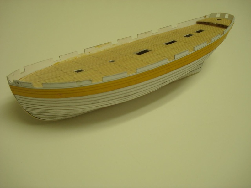
Thanks for the sage advice David. I don't believe that's the issue in this particular case, but it's certainly a point well taken. I'm curious if anyone has ever tried to use the pre-printed planks to aid in the building of wooden models? As far as I can tell, most of these kits don't include individual planks, but the Shipyard Alert kit does, and so does their Le Coureur kit. For the wood ship modeler, these kits seem to be excellent at illustrating the proper shape of hull planking as well as the joggling of deck planks into the margin strakes. Anyway, I'm discovering that card models are not easy, but they are fun. Here are some pics of the model just before I added the keel and glued the bulwarks into place. I'm learning that paint really does cover a multitude of sins and works very well on this model! Clare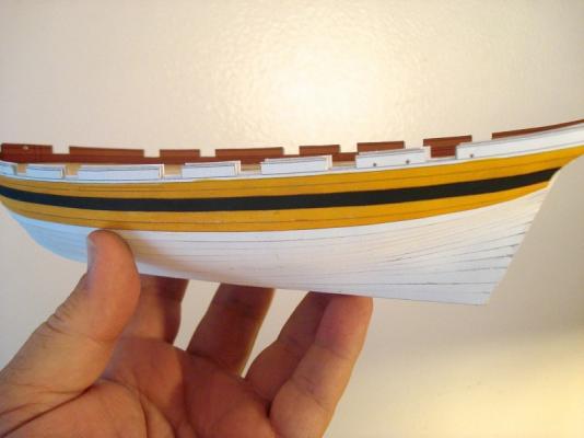

-
Hey Bob, Congratulations! You've passed the half-way mark, at least as far as the step numbers in the instructions go. Time to celebrate with some Sake? I really like the way the wipe on poly looks on your model, particularly on the thin, colored wood. It's all looking really nice. But, you're making want to build another Woody Joe kit now... Clare
-
Hi Ken, I'm going through basically the same thing as you. I have a model of a colonial schooner and I'm working on my rigging/belaying plan. Hahn's drawings aren't much help except for the overall rigging plan and his book The Colonial Schooner basically is just a place to find those drawings. I found little else of use in it regarding rigging. I wouldn't trust Petersson's book either – very specific craft and periods. But, as Russ and Greg have said, the Sultana should be a good guide. I have the Model Shipways' plans and they look pretty reasonable since both my schooner and the Sultana belay lines to shroud cleats, mast cleats, timberheads and a few to cross bitts. The Hannah should pretty much be the same and it's of the right period, right type, similar size. Clare
-
This is a great discussion and I am enjoying following everyone's posts immensely. While I'm kind of an advocate of the old solid hull kits, I had to "like" Brian C's post because it's honest and I think it adds a lot to this discussion. Plus, I agree, it is a shortcut. But, like neptune (John) points out, so are all kits, really. Still, I think there need to be some kits that are more shortcut than others. Anyway, the degree of shortcut depends a lot on the quality of the solid hull and availability of good plans/templates. Some kit manufacturer's hulls are less shortcut than others and can require a lot of carving and sanding to finish/correct, while others may require very little. So, I wouldn't say that all solid hull modeling is harder or easier than plank-on-bulkhead. It can be harder or it can be easier depending on what level of perfection you want and that's what I like about them. I like to see solid hull kits remain on the market through BlueJacket, Model Shipways, A.J. Fisher (still around), and even Amati (1/80-scale J-Boats kits with pre-carved hulls). Clare
-
Beautiful work Bob! For me, planking the deck seemed to take forever. I guess it had to do with cutting all those short pieces and also making the supporting beams and making sure the planking panels all fit nicely. Like I said, you've done a beautiful job. Clare
-
Pete, your models are truly awe inspiring, and I particularly love your solid hull work. This topic wouldn't have been complete without your input! Clare
-
Andy, beautiful work you've done and congratulations! Hey, on those portraits, now which one is you and which is the original? Clare
-
I've built several solid hull models, some from kits and some scratch. Personally, solid hull is still my preferred form of scratch building. Solid hull kits have the beauty of construction flexibility. A beginner can take a solid hull kit and do almost nothing to fix up the shape of the hull (depends a bit on the manufacturer) and build a nice looking model. A more advanced modeler can take a solid hull and fine-tune the shape to build an accurate model. As pointed out, one can plank over the solid hull, which provides a solid foundation for the planking. Going a step farther, a solid hull can be carved down to accommodate the planking more accurately (the thickness of the planks do change the dimensions of the hull slightly). Solid hull kits avoid some of the pitfalls of plank-on-bulkhead modeling since you don't have to worry about shaping planks unless you choose to plank over it, and you're less likely to end up with bumps and flat spots, which can often appear on plank-on-bulkhead kits if you're not careful. It's true that I've seen some people be a bit disrespectful regarding solid hulls, but not really here. But it did take me a lot of work on another forum to convince them to go beyond listing model categories as: Plank-on-Frame, Plank-on-Bulkhead and Other Models. But, there's a lot of "solid" support here (pun intended). Well, all of this is to say, build your model and enjoy it. I hope you start a build log and post photos of your progress. Clare
-
Well said Don! I haven't started a build log because I was just experimenting with one of the smaller Shipyard kits. I wanted to find out what it was like to work in paper and I had no ties to finishing it, so I didn't want people to be following something I wasn't necessarily going to complete. However, it's actually turning out to be so much fun and such a nice build that I'm now thinking I may continue with it and turn it into a build. I will decide soon and I would say the 1:96-scale kit can be just about as nice as the 1:72-scale kit. You just have to do a lot more gluing and cutting. And, of course, everything is smaller. Stay tuned if you're interested. In the meantime, I started a write-up/discussion about the kit here: Shipyard H.M.S. Alert, 1777, 1:96-scale Paper Model kit Thanks, Clare
-
Trusses and Lifts and Jeers, Oh My (Fair American)
catopower replied to GaryKap's topic in Masting, rigging and sails
Hi Gary, Sorry, looks like I did misread your post. Very good point about the Model Shipways' kit being a model of a model. I believe there are other oddities from the Rogers model like the undersized gun ports? Clare -
Geoff, Long ago, I had purchased something from this outfit. They're in Israel, I believe. I think it is either run by, or they work with, a guy who is a ship modeler. I did receive the plans I ordered, but you could tell they were copied from some kit, but not one that I'd ever seen or heard of. I think it was some Eastern European manufacturer. As far as I know, they might actually have the rights to sell the stuff, but there was something just not quite right in my dealings with them. The plans had no scale on them, belaying plans were numbered, but there was no guide as to what the numbers corresponded to. Lots of issues like that. So, the plans ended up being worthless. I've since warned ship modeling sites about them. One old site used to be a "dealer" for them, but after I and a few others complained about the company, they decided to break their ties. I suspect you'll get your plans and they may or may not be useful, but I think we're all better off not dealing with them. Not much you can do beyond that except learn from it. Clare
-
Trusses and Lifts and Jeers, Oh My (Fair American)
catopower replied to GaryKap's topic in Masting, rigging and sails
Hi Gary, Personally, I wouldn't be too quick to disregard Erik Ronnberg, Jr's instructions. He's an outstanding model builder and researcher who's work is very well known. Petersson's books are great, but I think people put too much emphasis on them. His drawings are extremely useful, but generally taken from a single contemporary model – A British warship model donated to the Briston Industrial Museum in 1844. So, what period does the rig represent exactly? Anyway, I had to look up what you were referring to because something didn't seem right. That lift arrangement you show is only for the lower yard lifts. These yards are fixed, so they aren't raised or lowered by the lifts. My take is that if necessary, temporary jeers could be rigged up to lower or raise the yard down as needed. Otherwise, the lifts only serve to keep the yard steady. But, I was surprised at your mention of no slings, so I looked through the instructions again and there is in fact an illustration, fig 38, that shows the lower yard sling in place. Though I never built her, the Fair American was one of those life-long loves in ship modeling for me. Hope you are enjoying the build – I'm quite envious! Clare -
Running the risk of filling up this forum with topics about the Shipyard HMS Alert kits, I had to share this. This guys build is just incredible. Shows what you can do with the Shipyard "Laser Cardboard Kit". I just ran across this yesterday and I initially posted it my own own topic about the smaller scale Shipyard kit. I was afraid it would just get buried in there, so moved it to this new post. These are links to the 1:72-scale kit that Janet B is building and I know others are building or interested in building – Ages of Sail just sold another one of these kits just a few days ago, so it got my attention. I see a reference in the build logs to the builder living, or had lived, very close to my location. I'm temped to seek him out, though this stuff was done about 6 or 7 years ago: On a German Site: 1/72 Alert Awesome build log On Flickr: 1/72 Alert Awesome build pics I'm tempted to toss out what I've done so far and to just buy this kit. Nice 5-hole deadeye on that mainstay. Anyone know if that's in the kit or if the builder made it? Nice touch with the served lines and mouse's (mice?) too. I only wish he hadn't put it under full sail on the launch ways... Still, a beautiful job on the model. Clare
-
Shipyard H.M.S. Alert, 1777, 1:96-scale Paper Model kit
catopower replied to catopower's topic in Card and Paper Models
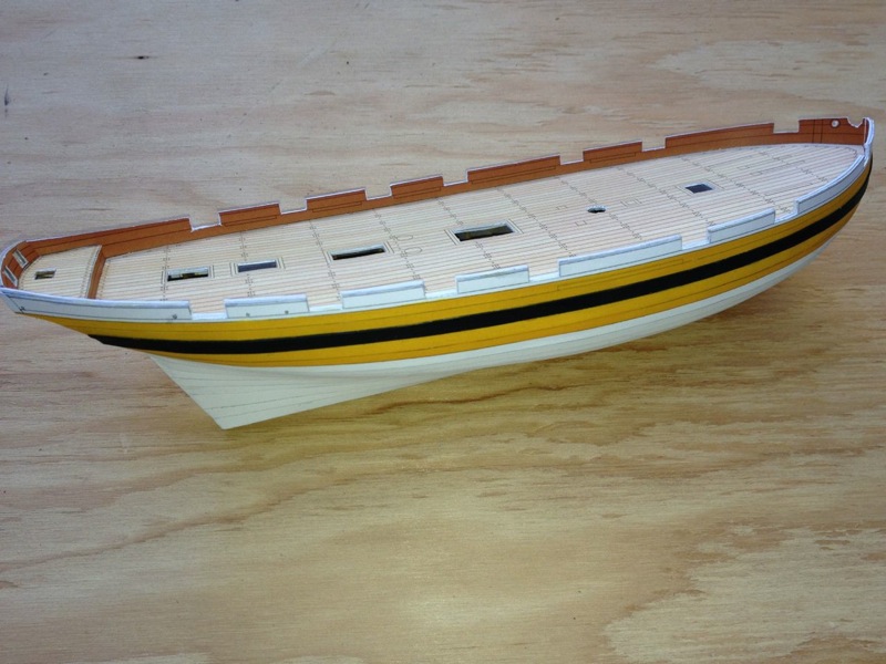
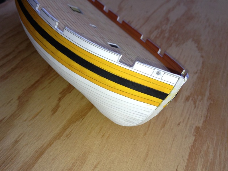
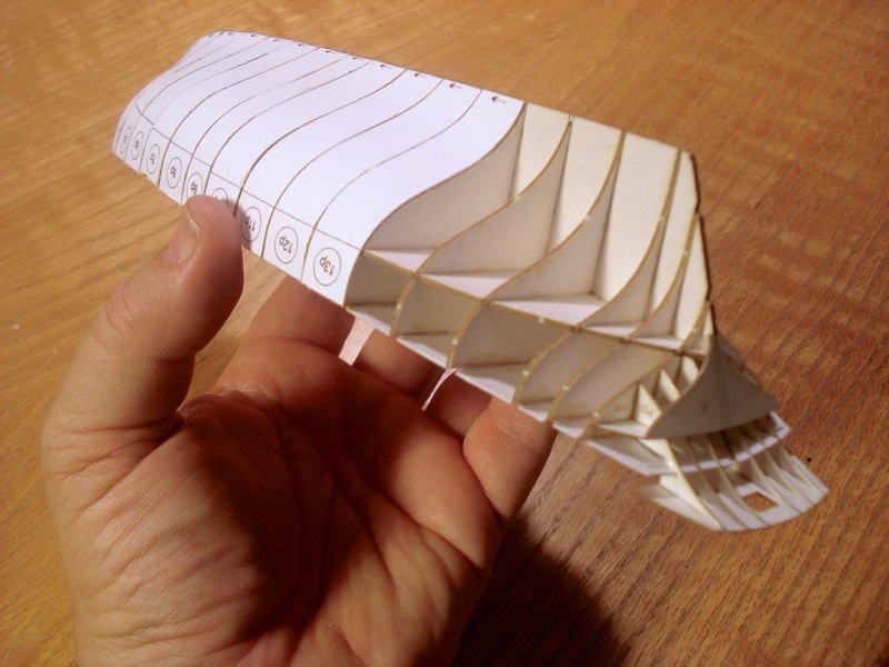
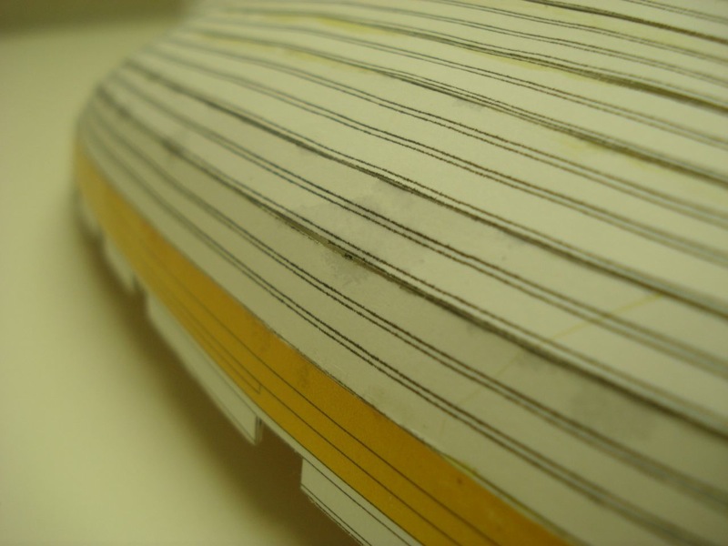
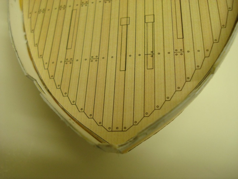
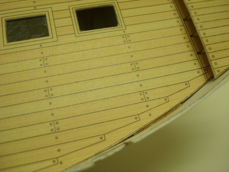
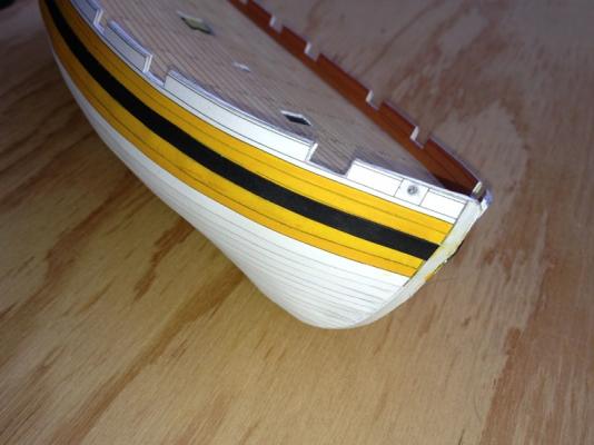
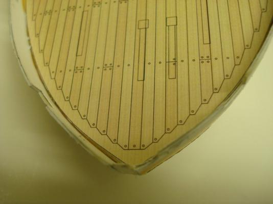
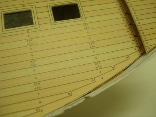
Thanks for the supportive comments, Chris. I've run into some of my first limitations, either skill-wise or model scale-wise. On these kits, the hull planking is pre-shaped, which is really nice. But, all of us here know the complexities of wooden ship hull planking. The hull of this kit, and probably of most Shipyard kits I expect, are laid in 3 layers. The first layer was shown in the last images of the model I posted, and is made up of filler sheets that span the space between individual bulkheads. These are thin paper, no build-up, and pretty easy to add. The next layer consists of printed strakes, 2 to 3 planks wide. The printing serves as a guide for laying the final layer, which is made up of the individual planks. So, anyway, the second layer, made up of several strakes, is a bit tough to add so that it's nice and smooth. I've found that in order to fit them correctly, I get a little bit of buckling along one edge and a wavy edge is formed, consisting of bumps and valleys. I've compensated for this by taking the bumps and tacking them down firmly with instant CA. There are still the valleys, which of course get tacked down as well since the CA wicks into them. But, I take the point of the Xacto and cut them loose from the hull, causing them to rise up ever so slightly, somewhat evening out the strake. Is this the best way to approach this issue. Is it a common issue with Shipyard kits? Or is it a sign that perhaps I started off wrong when I attached the bulwarks section. It wasn't very clear how to add that piece, whether to glue it so it sits on top of the deck or so that it's fixed along the hull, right at deck level. First Layer of the hull Second Layer of the hull Looking back, I guess there are ways to figure this out, say, by test fitting other parts to see what allows them to fit most easily. But, I did as best I could and ended up gluing the bulwarks piece to the hull right at deck level and I THINK this is correct. But, like I said, the hull planking isn't laying PERFECTLY. Maybe this is just how it's supposed to go? I know this is starting to look more like a build log, but I'm really reluctant to treat it like one. I really like posting here in the card model section. I find it much easier to find things here and it also makes it easier to find other card modelers. Some card models in the build log section are not marked as such. That said, I thought I'd post a couple more pics of what I've been doing on this 1/96 scale Alert... Second Layer completed The Pre-Printed Decks are pretty cool All is well and this kit is very nice, especially for the price. But, I'm starting to appreciate more and more the value of NOT having parts pre-colored for you. I've ended up with a few glue blemishes, shades of the days of building my first plastic models as a kid (so many gluey finder prints on those early models). I've used the paints I bought from Shipyard to even out the coloring of the pre-printed bulwarks. It's better, but not great. And now having seem some EXREMELY AWESOME pics of a build of Shipyard's 1/72 scale HMS Alert kit posted on another forum and also posted on Picasa, I'm drooling over the bigger kit. Also, I haven't checked it out closely, but I believe the parts are not pre-colored, so I think that makes it easier for those of us who are comfortable with painting anyway. Okay, now to TRY to get back to my regular projects... Clare


-
Shipyard H.M.S. Alert, 1777, 1:96-scale Paper Model kit
catopower replied to catopower's topic in Card and Paper Models
Hi Janet, That's the nice thing I see about these paper models, they don't take much in the way of tools or space – No $500 tables saws or thickness sanders or drill presses, just scissors and razor blades... Clare -
Shipyard H.M.S. Alert, 1777, 1:96-scale Paper Model kit
catopower replied to catopower's topic in Card and Paper Models
Hi Anthony, The sails do seem to be very nice and the lines appear pretty well to scale. I finally open up the package today to check them out. They're pre-printed, but only on one side. I don't know if you're expected to sew them or not, though I seem to recall having seen instructions somewhere that call for the bolt rope to be glued on. But, that's what I normally do with sails anyway. By the way, this isn't formally a build log yet, more a review of the kit, which is why it's still in this forum. While I am playing around with the build, I'm mostly doing it to check out what these kits are like. It's been kind of fun though and I am getting into it. The build log you pointed out should be very interesting. It's actually a different kit, the 1/72 scale "Laser Cardboard Kit", while mine is the 1/96 scale "Paper Model Kit". We'll see how much I get sucked into this card stock world – I also have the Santa Leocadia Super Modellar Plans, which includes all the hull parts. AND, I just ordered a detail kit for it from GPM as well as some of their CA glue based on a recommendation here on MSW. It's so much cheaper to work on card models, even though I'm ordering stuff from Poland. Clare