catopower
-
Posts
1,915 -
Joined
-
Last visited
Content Type
Profiles
Forums
Gallery
Events
Everything posted by catopower
-
Hi Dr. Per, don't take it too hard. It's difficult to overcome a name that is so connected to such an extremely successful show. That said, perhaps we can all work a little harder at not taking over another person's thread with off-topic comments? I myself have purchased a few of the Vanda-Lay products. When working on my first scratch builds, I used their Acra-Mill Plus set up to help me make my own blocks. It actually worked quite well for cutting the strips to size, thicknessing them, and then slotting both single and double sheave blocks and also slotting them for the stropping rope. The AcraMill Plus uses the same "universal" tool holding clamps, which I agree aren't a great design. They do work, but as you said, they can mar the plastic of the Dremel tool. Also, it's possible to clamp too tightly and affect the motor itself. But, the parts are well machined, and the Vanda-Lay tools are particularly useful when you don't have much room to work. They also used to make a Treenail Maker that I wish was still available. Very good review! Clare
- 19 replies
-
- 6
-

-
- VandaLay
- Industries
- (and 6 more)
-
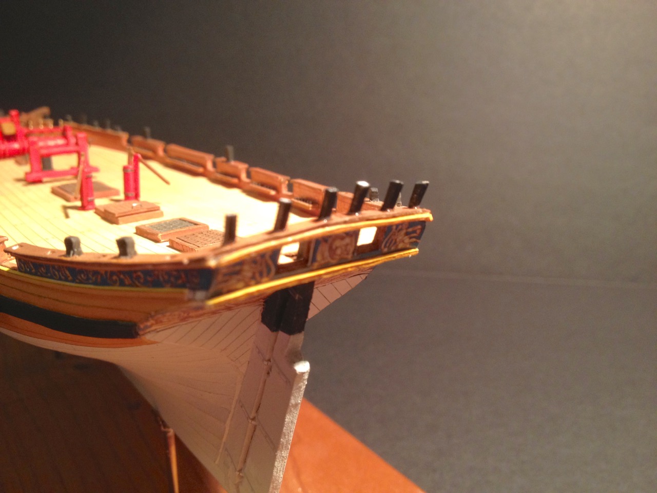
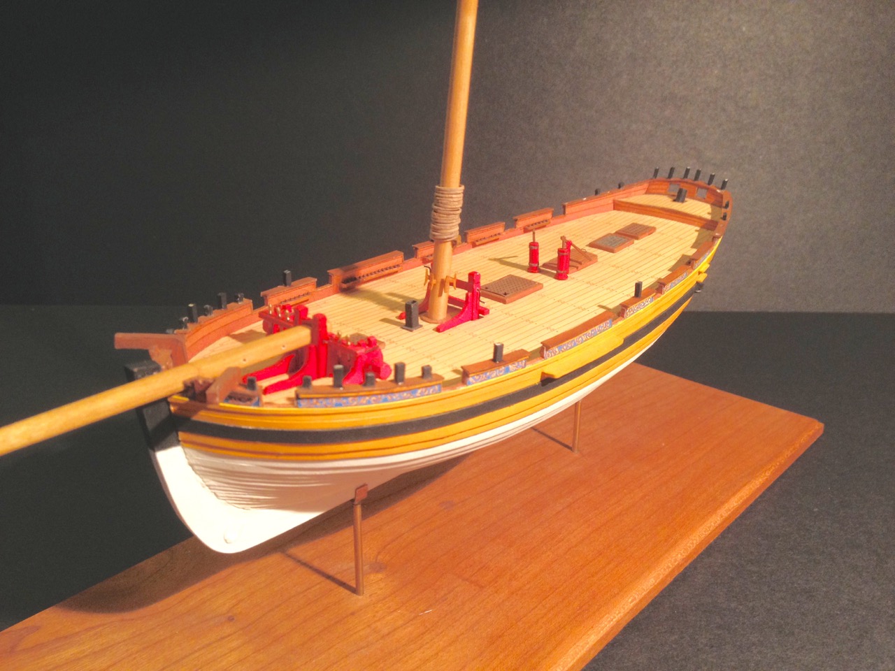
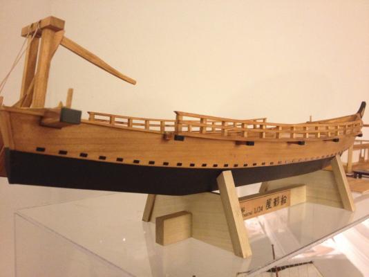
 The taffrail is now complete. Was a bit of a challenge getting it all together, but it seemed to turn out okay. I still have some small details to add, mostly the beds for the mounting of the swivel guns. Besides that, nearly all the hull detail on this model is done. Next step will be to add the cannons into place. 1/96 is probably too small for me to rig tackle blocks, but I'll think about it. This ship has 12 guns to rig. It's not like it's a 38 gun frigate, and there is a lot of open space on the deck, so I'll have to give it some thought. Also, rigging is coming up pretty quick and I have to start working on the shrouds and adding blocks to the mainmast. More on that next time. Clare
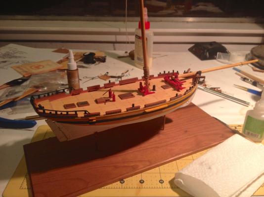

- 121 replies
-
- 14
-
-
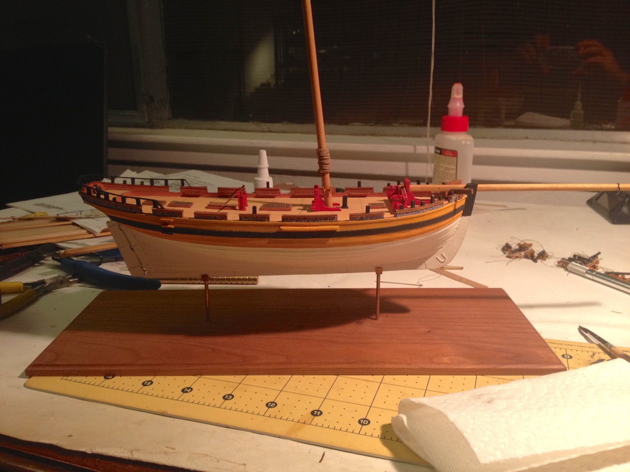
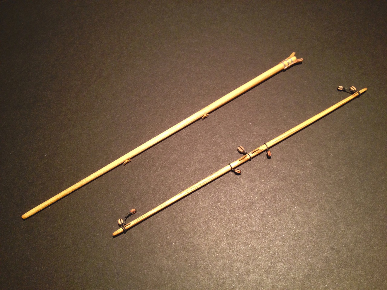
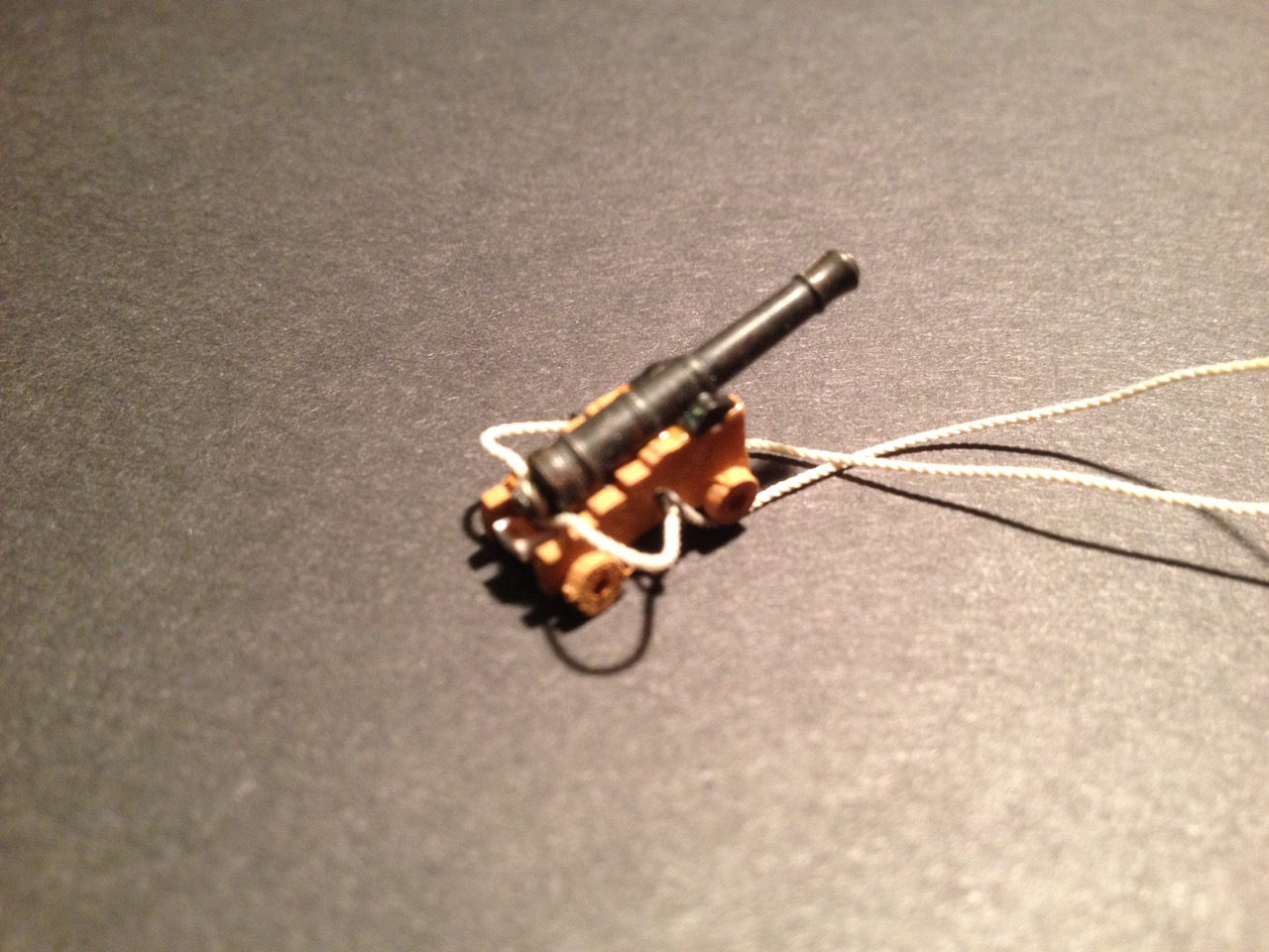
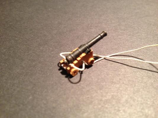
Didn't do much on the Alert while finishing up the Yakatabune model. But, now that that's out of the way, time to put some work in on the Alert again. This year, I decided not to risk any damage to the model by bringing it to the NRG conference, but a number of people asked about it. So, I kind of regret not taking it. For one thing, it serves as a great advertisement for Shipyard paper model kits in general. However, this model is far enough along that I now need something in the earlier stages of construction again. I do have an HMS Mercury kit in 1/96 scale that will probably do the trick. I also have the GPM detail kit for it. Plus, I believe that there's a set of sails and a masting kit at Ages of Sail that's been part of a box of stuff that's just been hidden on a shelf for the last year and a half. So, that may be the next background paper model project. In the meantime, I cut a thin strip of photo paper that I printed a black line on. I then painted the edge of the thin strip and cut it in short length to serve as trunnion caps on the Alert's cannon carriages. I've also been working on the spars and added the yard to the topsail and the gaff to the mainsail. I also added swiss pear blocks to the spreader yard, but I've been feeling like I want to make as much of the model from paper as possible. So, I'm going back and adding paper blocks in place of the swiss pear ones. They don't look as good, but the more of the model that is paper, the better, since it IS a paper model. I've also started adding the stanchions of the taffrail that surrounds the quarterdeck. This is one of those things where I "thought" myself to a standstill. Having thought less about it, I've now started to make a little progress again. I'll swap the blocks and see if I can't finish the taffrail soon. With that and adding the cannons done, it will officially be time to rig. Clare


- 121 replies
-
- 13
-
-
Bob, your Higaki Kaisen is looking great. Sorry you didn't make it to the conference with your model. I was hoping to meet you. As it was, this year's conference was sort of the opening of Japanese traditional boat models. Speaker Douglas Brooks gave a talk that was extremely well received and he was very happy about how well the conference went for him. I think he sold almost all the books he brought. There were two models he brought that were built by his teacher in Japan, so there was some Japanese boat models there. Any thoughts of making it to next year's conference in San Diego? Regardless, I'm enjoying watching your progress on the model and getting some inspiration from your work! Clare
- 196 replies
-
- 7
-
-
- higaki kaisen
- woody joe
- (and 1 more)
-
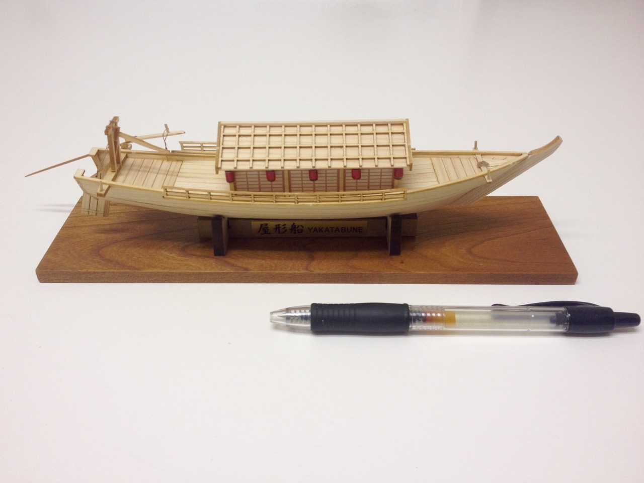
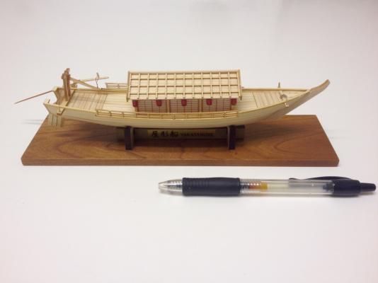
Beautiful job on your Yakatabune, Richard! I love the way you built the lighting. Hey, I know what you mean about having to reattach the support rails. I had the same issue on my 1/24 scale version. Congratulations! Clare
- 45 replies
-
- 3
-
-
- yakatabune
- woody joe
- (and 1 more)
-
Cat Head dimensions
catopower replied to BANYAN's topic in Building, Framing, Planking and plating a ships hull and deck
Pat, nice coppering job. And I love the feathering screw – Very cool! Your build has me thinking about my early steam era projects. Gotta get back to the Saginaw (1859), plus continuing development work on the Kanrin Maru (1856). Very inspirational! Clare -
I appreciate all the supportive comments, All. Thank you. Hope to see some more ship modelers trying out these kits. And, also hope to see some of you in Mystic! Clare
- 106 replies
-
- 2
-
-
- Japanese boat
- Wasen
- (and 2 more)
-
Thank you Mark, Grant, Jeff for the kind words! And, arrrr, I think I WILL have a beer now! Clare
- 106 replies
-
- 4
-
-
- Japanese boat
- Wasen
- (and 2 more)
-
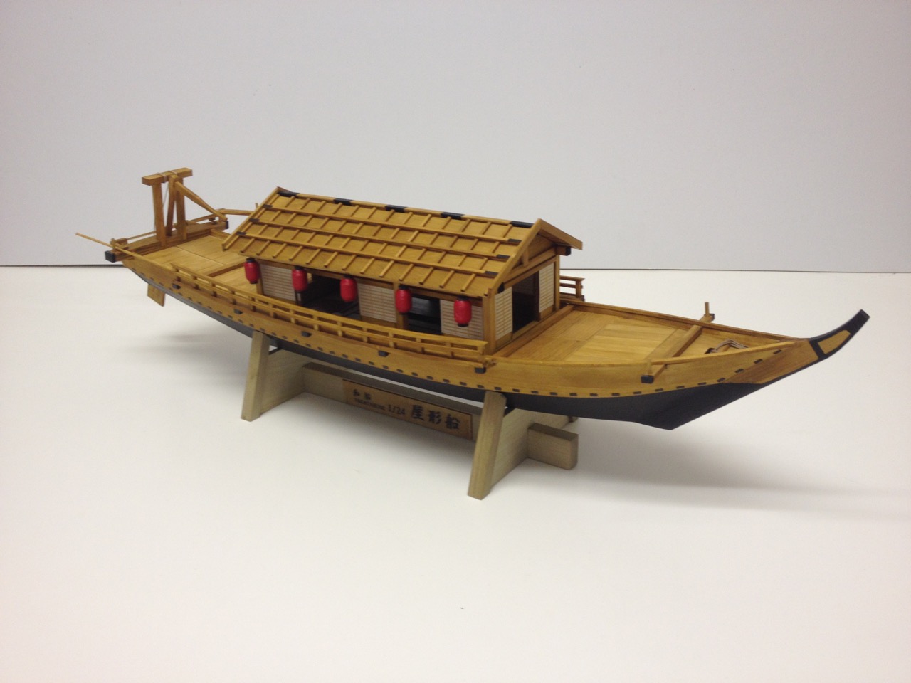
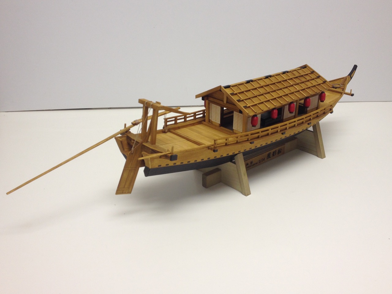
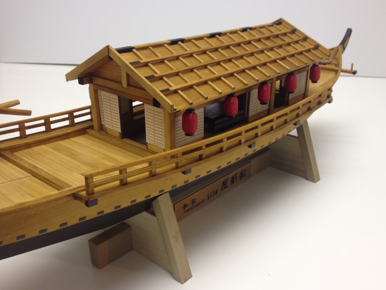
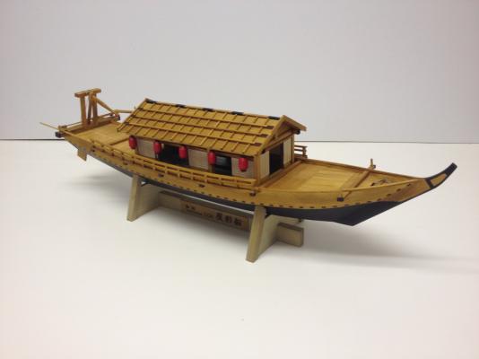
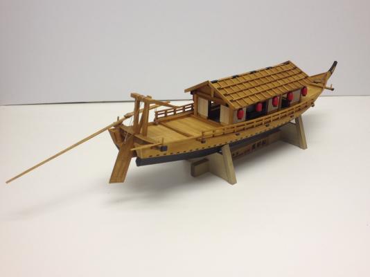
Well, I'm just going to jump to the end of the build here because I'm there! I added some paint details inspired by the Japanese paintings of these boats in Edo times. Yesterday, I whipped together a display pedestal to match the two I built for the Higaki Kaisen and Hacchoro models. Now, I can get back to other projects for a bit and experiment a bit with ways to make the hanging lanterns inside to light up the interior a bit. Pretty hard to see in there right now. At this point, I'm mostly out of larger scale updated Edo Period Japanese boat kits. However, I do have two of their older coastal transport kits (Sengoku Bune), which pre-date laser cutting. Those kits are larger than the Higaki Kaisen. What I find interesting is that they are also more like traditional ship modeler's kits. That is, they provide patterns for cutting the hull strakes from sheet wood, frames are not pre-cut, but have to built from posts and beams, etc. Many parts are pre-cut, but there is no weight or space wasted on die-cut sheets. Instead, all the pre-cut parts are neatly packaged for you. There were two of these Woody Joe coastal transport kits. The Kitamae-bune, is now out of production, and hopefully, we'll see an updated version soon that's as nice as the Higaki Kaisen. The other is the Sengoku-bune, which they still sell. This one is kind of a generic version of the coastal transport, not quite as large as the Kitamae-bune, which operated from ports along the Western shores of Northern Japan. Either of these would make a better display model than the Higaki Kaisen because they are larger. They are incorrectly labeled as 1/30-scale kits, but are closer to 1/53 to 1/60-scale. Been thinking that a 1/48-scale model would be ideal for display purposes. Also, it may be time to try to scratch build a boat based on the work of boatbuilder Douglas Brooks, who'll be speaking at the NRG conference in a couple weeks. I'll keep you posted! Clare

- 106 replies
-
- 15
-
-
- Japanese boat
- Wasen
- (and 2 more)
-
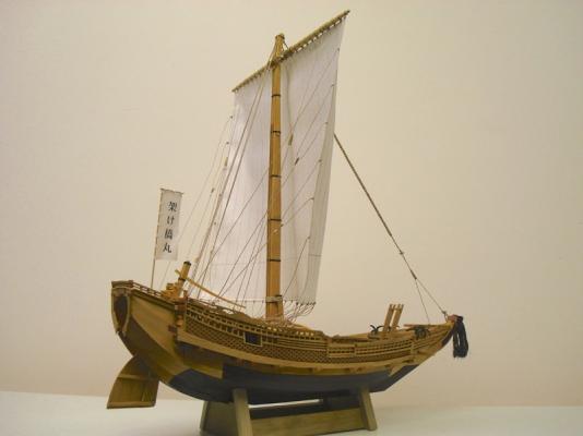
Hi Druxey, I thought it would be a lot more difficult and time consuming than it's turned out. It's a good thing I was dwelling on the one translation in the instructions. Otherwise, I'm sure I would have done things a much harder way! Jeff, here's the Higaki Kaisen I was referring to along with the other Woody Joe kits I've built since... Higaki Kaisen Hacchoro - Fishing Boat Hobikisen - Fishing Boat mini-kit Yakatabune - mini-kit Clare P.S. Make sure to check out Bob Riddoch's Higaki Kaisen build here: http://modelshipworld.com/index.php?/topic/7020-higaki-kaisen-bob-riddoch-woody-joe-172-scale/#entry206798
- 106 replies
-
- 12
-
-
- Japanese boat
- Wasen
- (and 2 more)
-
Hi Jeff, thanks for the nice comments. You know, I wasn't into Asian ships or watercraft either until about 2 years ago when I found Woody Joe's Higaki Kaisen kit and some articles about the ships. Now, I can't stop! The next Japanese watercraft I do will either be an attempt to scratchbuild a small Japanese boat, while learning how the actual boats were constructed, or I'm going to build another ship like the Higaki Kaisen, but one that is a larger scale. Clare
- 106 replies
-
- 5
-
-
- Japanese boat
- Wasen
- (and 2 more)
-
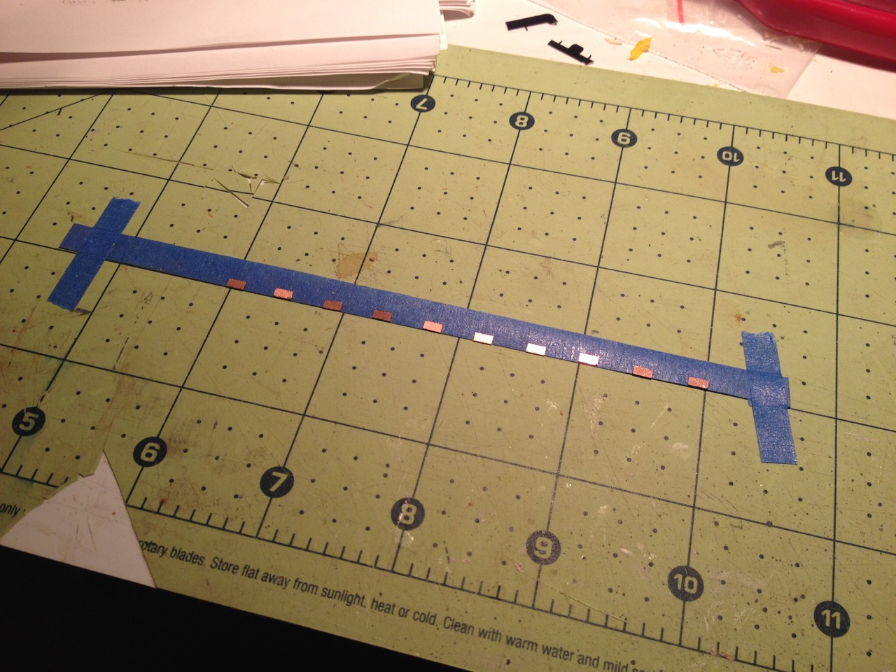
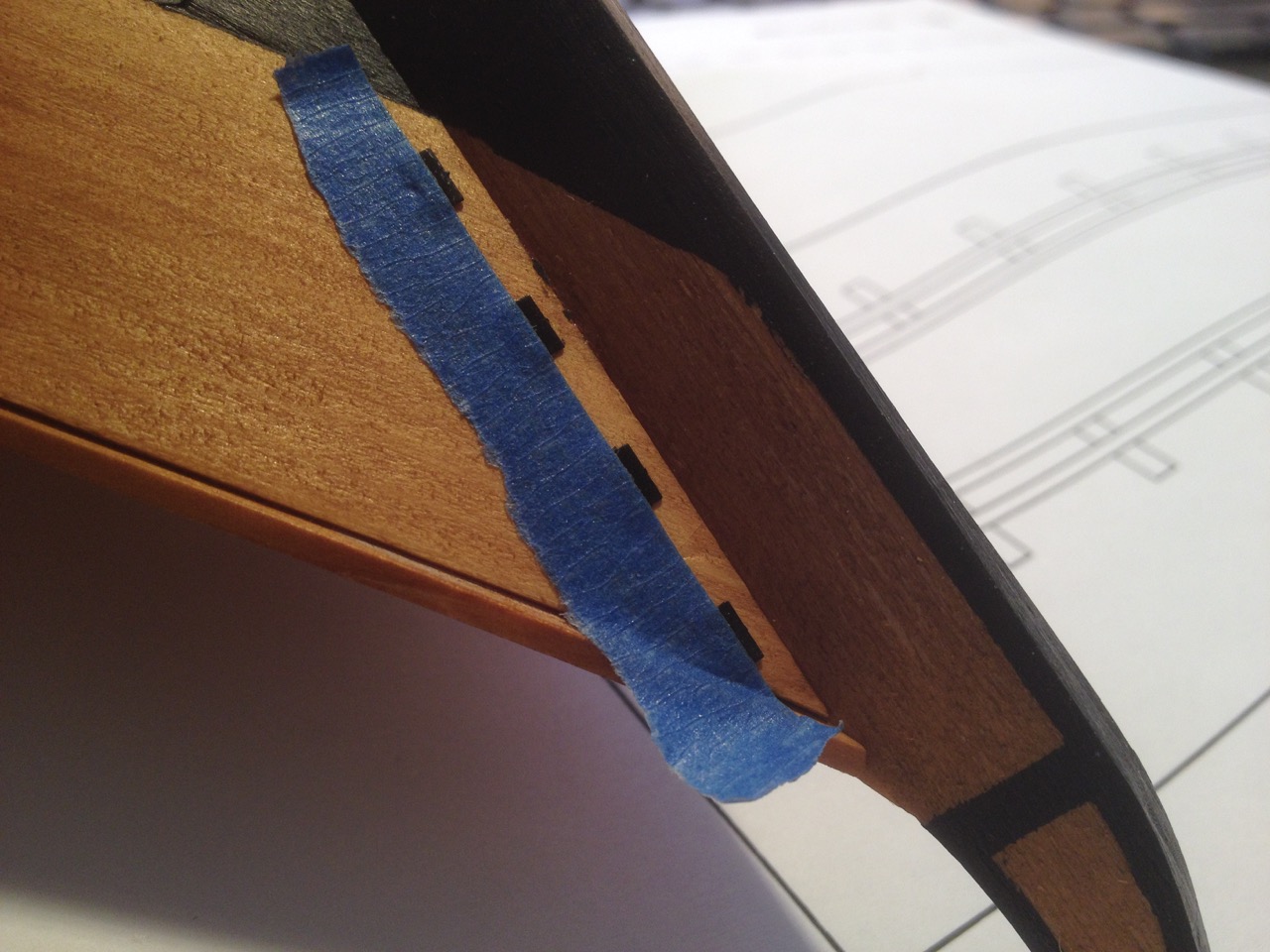
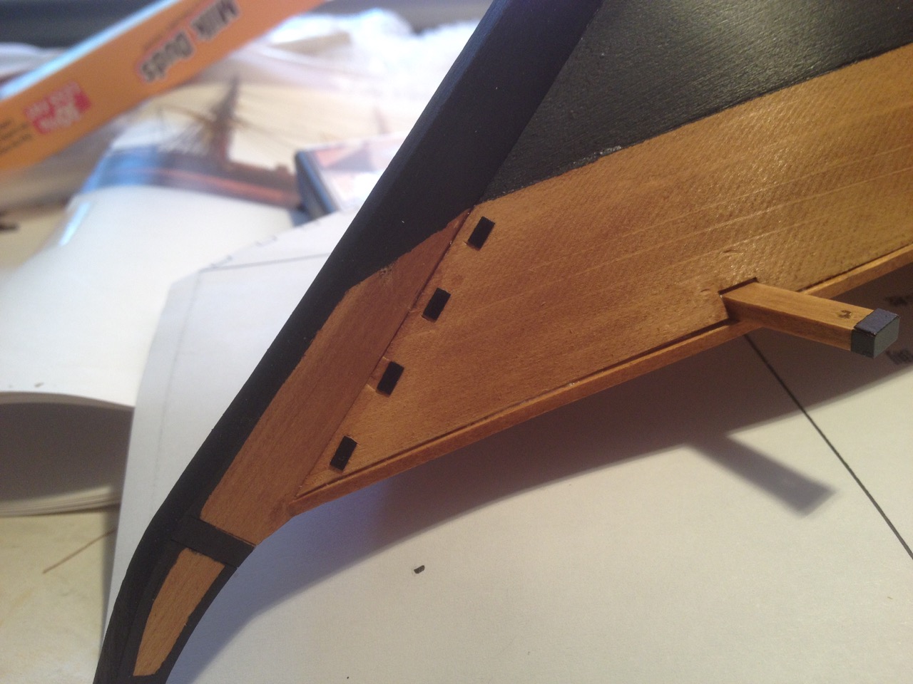
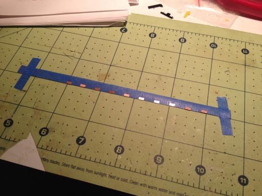
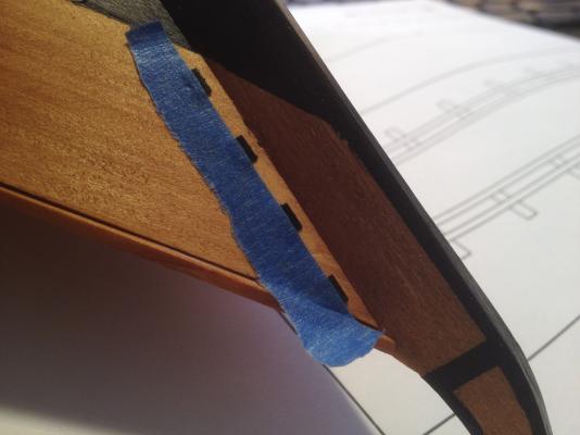
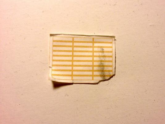
Thanks Bob. I think this is working out pretty well. The model is supposed to have a row of plates at the base of the upper plank as well as the lower plank. But, since I've painted the lower plank black, I'm not sure that it's necessary to add the plates there. Real plates were actually inserted into recesses, and I know that on many boats, the lower recesses were often filled with putty instead. I presume that would then be painted over after the puttying. The trick after all this is done is that there were often plates, or maybe they were just painted areas, on the deck house too. Not quite sure how I'll deal with that yet. But, in the meantime, I was able to finish off the row of plates on one side of the boat. Turns out that a section of text I was having trouble translating was telling me to do pretty much the following: Laying out a strip of masking tape with sticky side facing up, in my case I chose blue painter's tape, I taped the tape down to a flat surface and placed one of the copper plates on the sticky face, right at the edge. Then, using the plans as a guide, I laid down copper plates with 7mm spacing in between. I trusted my skill with 5 minute epoxy since it's viscous enough for me to control and to keep a very thin layer, so I started with a needle, putting just a touch onto each plate, then going back and spreading across the plate with the side of the needle, regularly wiping off excess from the needle. I then peeled the tape up and laid the tape, sticky side down, along the edge of the plank, so that the plates were held in place in proper position until the glue set. I think the Woody Joe instructions suggest applying instant adhesive one plate at a time and then rolling the tape down so that it holds the glued plate into place, then applying to the next plate, and so on. This actually didn't take all that long. I carefully peeled up the tape after the glue had set, but while I could still push the plate slightly with my thumb nail to straighten and make final adjustment. With this one side complete, I feel like I'm nearing the final stretch on this model! Clare Edit: Forgot to add this shot of how I was using the tape method at the bow...

- 106 replies
-
- 13
-
-
- Japanese boat
- Wasen
- (and 2 more)
-
how do you decide on what kit to build
catopower replied to lionfish's topic in Wood ship model kits
1. Start by looking at all the kits I'd like to build 2. Eliminate all of those I can't afford, which is about 95% of those 3. Go back and add ones that MAYBE I could get if I stretch my budged a little (or a lot) 4. Look as which of those kits will be a nice step up in difficultly from previous builds. 5. Throw all caution and rationalizations aside and ignore steps 1-4 and go the one that just appeals to me most. The final kit usually ends up being something unusual that not everyone else is building, is an actual, researchable historic vessel or small craft, and gives me an opportunity to learn about the ship, the technology, the period history or culture that often isn't commonly known, at least to me. Then, like so many others, I usually put it in the closet with all the other kits I haven't had time to get to... Clare -
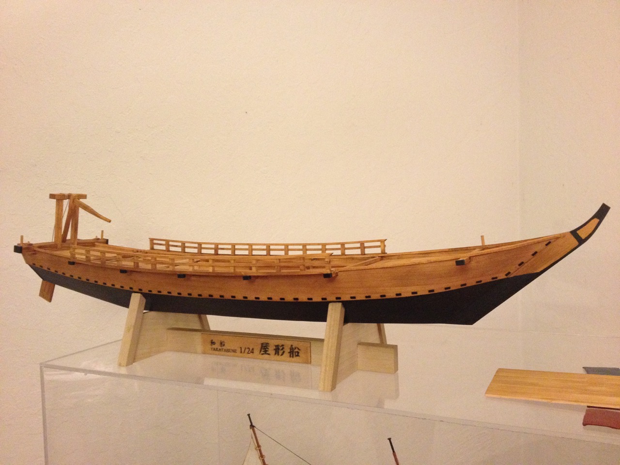
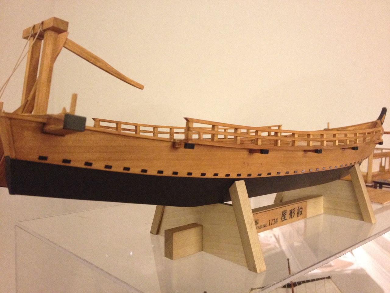
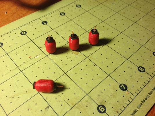
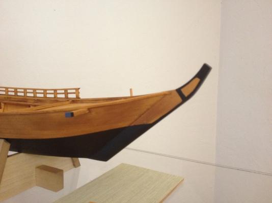
Kit Instructions: 27 Installing Lanterns • Use instant clear adhesive to attach the copper wire. Drill a hole 0.8mm to 1mm diameter. Insert wire, leaving 4mm length of wire sticking out. Lantern ends paint black Lantern body paint red Attach 5 lanterns on each side. (Use clear instant wood glue) 28 Stem Color Paint black above the upper etched line. I skipped the installation of the lanterns in step 27 for now, but I did paint them and added the mounting wire. The lanterns are resin and I cleaned them up as well as I could and painted them using water-based acrylics. Then, because I've altered the paint scheme on the model, step 28 didn't really apply any more. As it is, the model now looks like this: Sorry, it's a little bit blurry. Note too that I started adding the etched copper pieces from Step 29, which I'll get into next time. I sprayed the etched copper sheet with Rustoleum satin black and bent the copper caps to shape. After bending, the paint layer broke at some of the seams, to I resprayed the caps afterwards. These cover the ends of the beams as you can see in the photo. The next step is probably the one step that requires the most patience in this whole build. It involves laying down rows of copper pieces, evenly spaced and in straight lines. I'll get into some of the details later, but for now, here's a shot of how that looks: The original kit design calls for shiny copper parts, looking more like this, if you recall: Clare

- 106 replies
-
- 13
-
-
- Japanese boat
- Wasen
- (and 2 more)
-
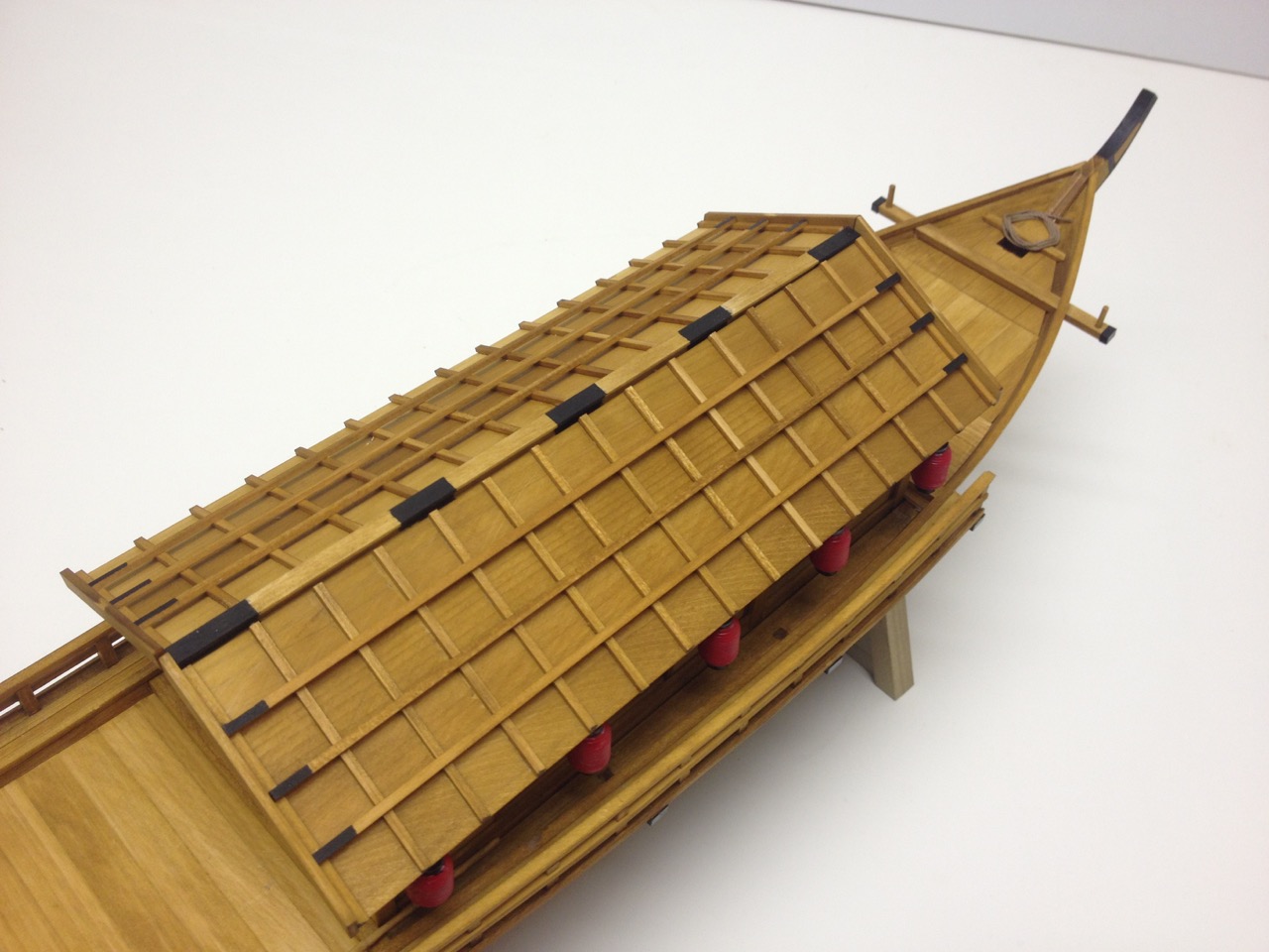
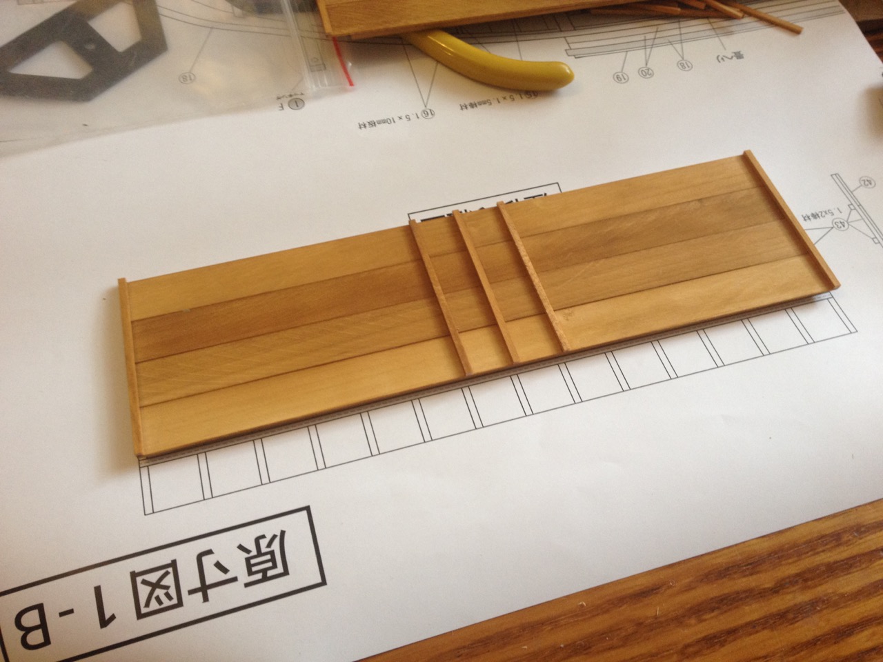
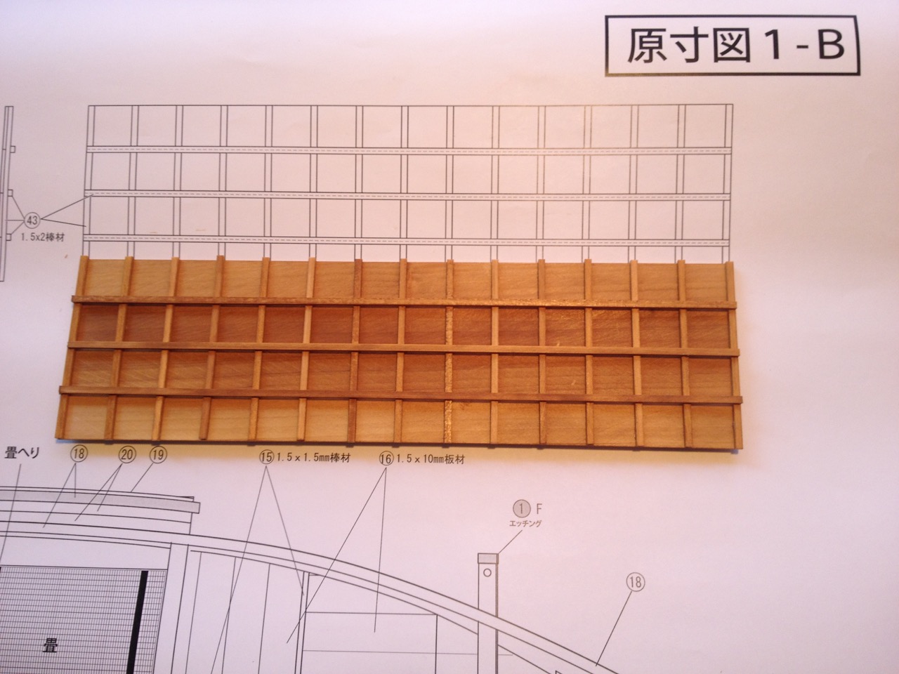
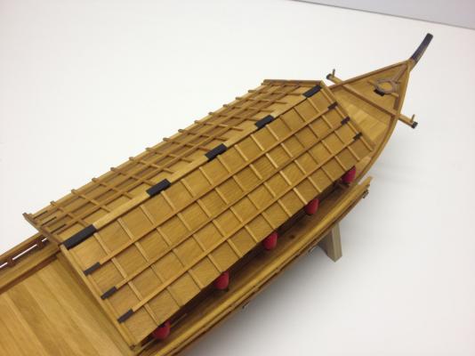
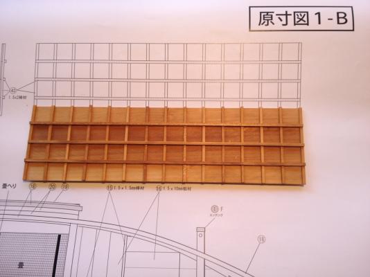
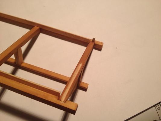
The next section is very simple and straight forward and involves finishing the roof panels and gluing them onto the roof framework structure. This involves the most cutting of strip woods since planking the deck. All the pieces are 1.5mm x 2mm and 15 pieces are glued across the roof planking. Nothing special to know here except that one of the plans sheets shows this in full scale, so I simply used this to mark the locations of each strip. With the shorts strips in place, 3 long strips follow the seams of the roof planks. The final result looks something like this... The Japanese text here is really simple and simply says: 26 Assembly of Roof Panels 2 • Please glue evenly using the plans. • Roof installation and a label showing... Installation of a building strip #44 There are some pieces shown in the instructions to install at this stage, but I'm still considering ways to be able to only temporarily mount the roof panels so I can access inside for lighting. Now, because I have more need to add this model to a display than I do to light it up, I'm going to put off lighting until after the rest of the construction is done. I can then display the models and after I take the display back down, that will give me time for the lighting details. I have, in the meantime, drilled out holes in the corner posts of the deck house to allow for wiring. I've also added holes and brass pins to allow me to fit the whole roof structure on and be able to remove it as needed. Finally, I dug out channels under the ends of the roof framework to allow me to continue the hidden run of wires to the underside of the roof. The next step in the instructions is to add the hanging lanterns to the edge of the roof. I painted the lanterns already, they are just resin moldings, so no LEDs there, but will not add them until I have a method worked out for making the roof panels removable. This means that the next step for my model is to add the photo etched copper pieces which will line the hull of the boat. Clare

- 106 replies
-
- 14
-
-
- Japanese boat
- Wasen
- (and 2 more)
-
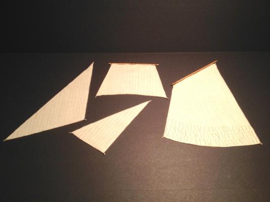
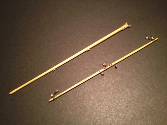
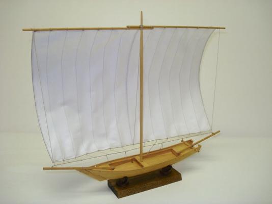
Nice work Bob! That mast looks great on the model. I really like how they included the sheaves at the top end of the mast. That was a fun sub-project, that and the bitts that are located inside the cabin. For the copper pieces, I used a contact cement, though it's not the stuff I have on the shelf now. I'm thinking that I had some Duco contact cement, but I don't see it online anymore. Or maybe I'm just losing my marbles... I have Dap contact cement on-hand, but it clearly states that it's not for use on metals containing copper. Sorry, that wasn't much help. I'm going to look for some other contact cement for the Yakatabune model as I'm getting to that point on the model too. Duco still makes some stuff that sounds like contact cement, but it comes in small tubes instead of a bottle. I'll probably give that a try myself. Hey, just curious, are you planning to use the kit provided sail, as-is? I did, but kind of wish that I had sewn it. Might be kind of small for that though. The pre-printed markings actually look unusually good. It even fooled a couple ship modeling buddies who thought I'd sewn them. Clare
- 196 replies
-
- 4
-
-
- higaki kaisen
- woody joe
- (and 1 more)
-
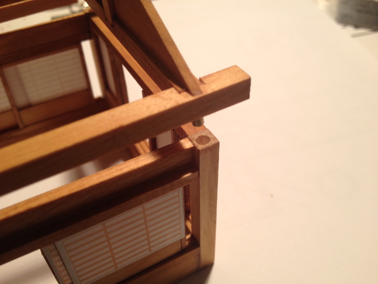
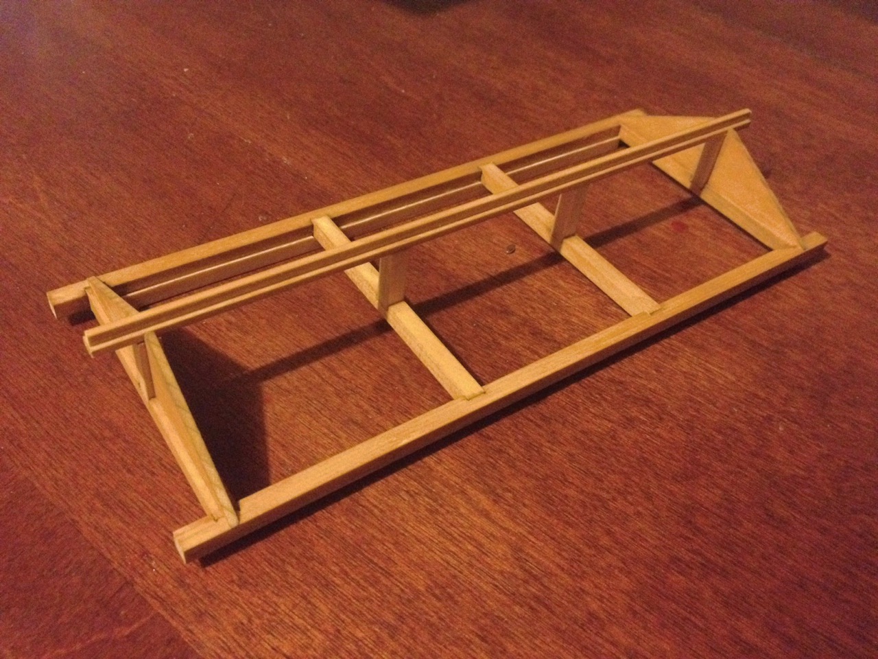
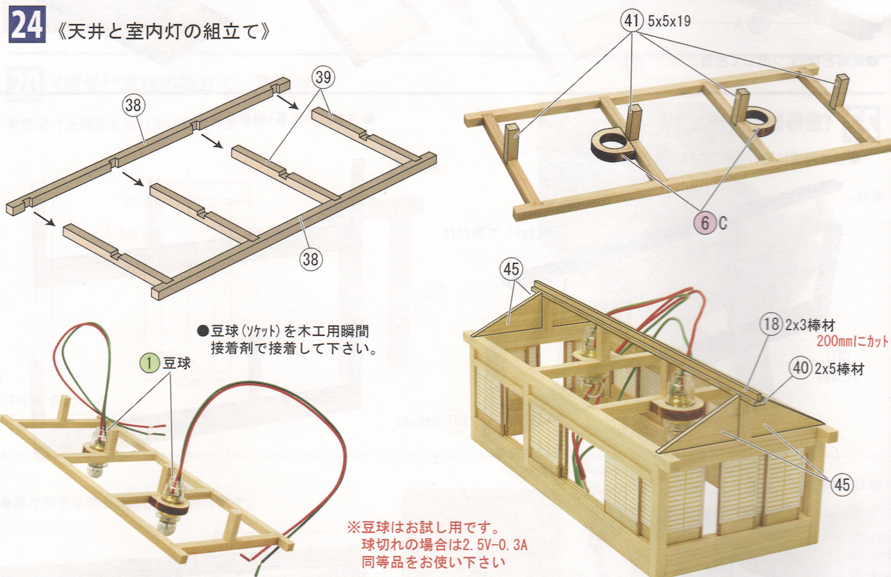
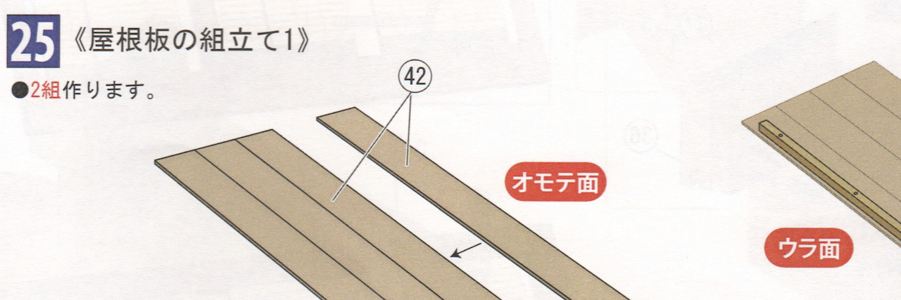
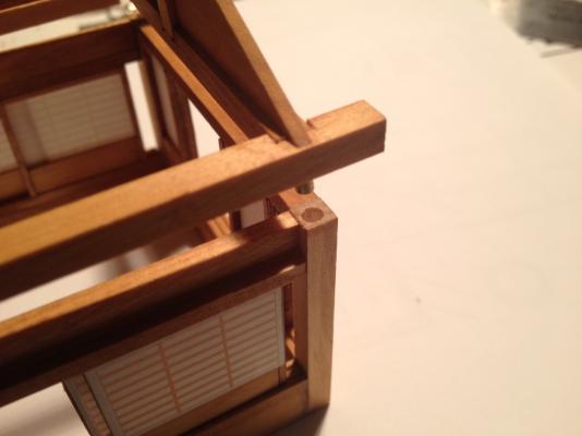
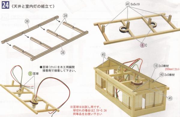
The next two steps are very straight forward and involve the deck house roof... 24 Assembly of the ceiling and Interior lights • Glue the sockets using instant wood bond adhesive There is a note in red at the bottom of this step that reads: Test the bulbs. In case of burn out, the bulb is 2.5 Volt, 0.3 Amps. Please use equivalent rating. Most of the parts in this step are pre-cut and only require assembly. Only Part 18 comes from the supply of strep woods. This is a 2mm x 3mm strip which needs to be cut to 200mm. Here's the section of instructions: Here's the roof structure I built. Because I'm planning on adding my own lanterns and using LEDs instead of the included bulbs, I didn't add the wooden mounts for the lights. I'll be dealing with lighting at a later time. Step 25 is nice and simple and just involves creating the roof panels. 25 Assembly of Roof Panels • Make 2 sets. Again, the parts are all pre-cut, so this is simple assembly. The labels in red simply say, on the left "Front Surface" and on the right "Back Surface". Now, I had one little accident with the deck house recently. I was working too close to it with a rag that had some wood oil remnants on it. The rag apparently touched one of the shoji screen panels and the oil marred its appearance. Worse, there was a spare included in the kit, but I couldn't find it. I came up with display options for keeping the panel hidden from view as much as possible. Fortunately, I found the small piece of paper, which had fallen on the floor at some point, but was in good condition. So, I removed the old one, as can be seen in the above photo (the tear is from removing it from the panel), and replaced it with the new one. No problems... Clare


- 106 replies
-
- 8
-
-
- Japanese boat
- Wasen
- (and 2 more)
-
Thanks for the nice comments Bob. I've been really enjoying this kit. Clare
- 106 replies
-
- 1
-
-
- Japanese boat
- Wasen
- (and 2 more)
-
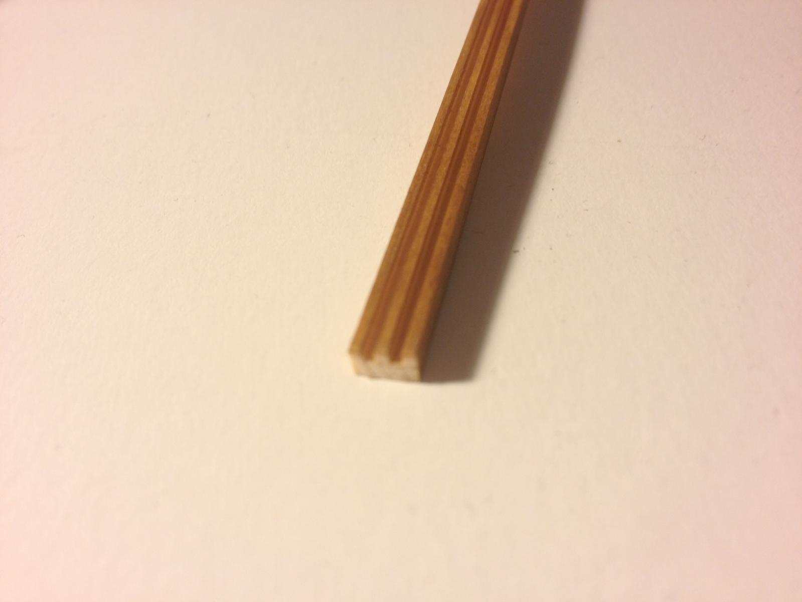
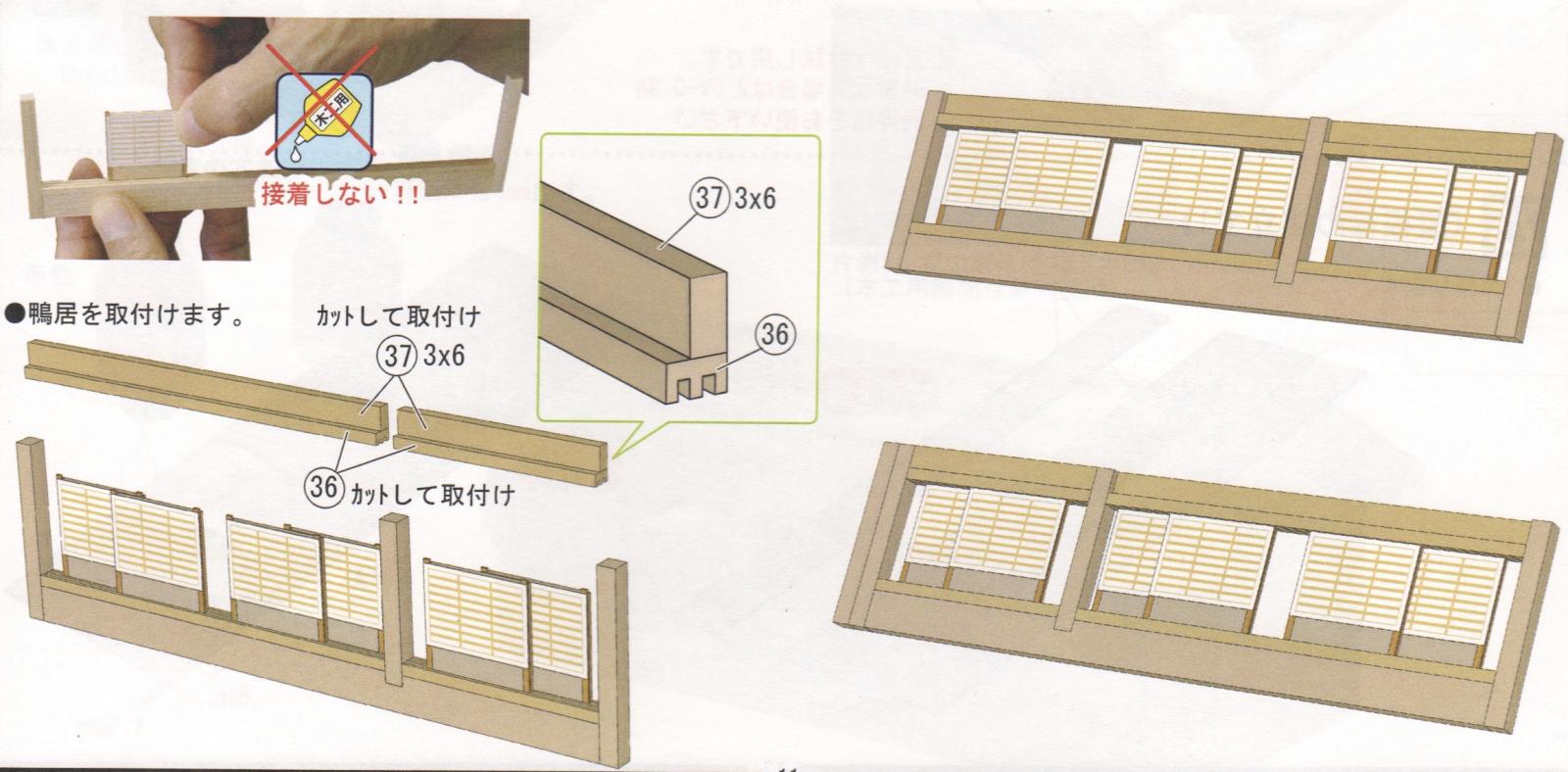
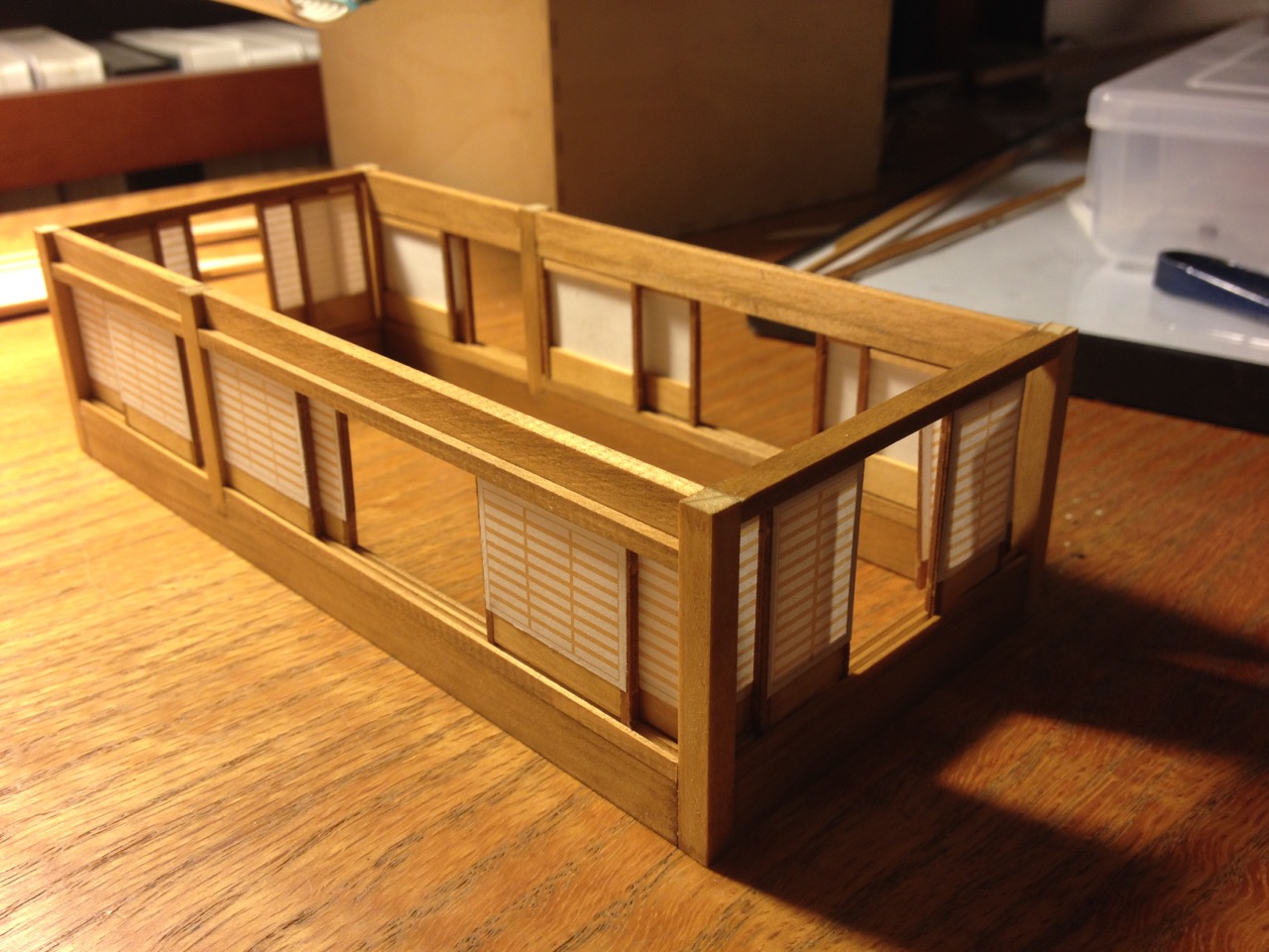
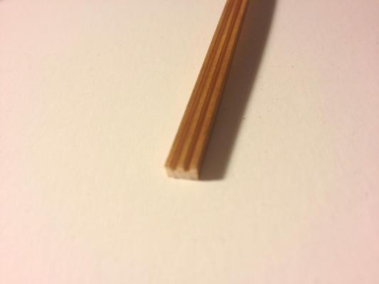
Thanks for your comments Druxey. I couldn't play it though because it was out of tune. And to answer your question... No... No, there is no end! So playing catch-up just a little, here the rough text for step 22: 22 Assembling the sides of the boat cabin • Install the vertical columns • Cut and install part 36 to fit. • The left and right cabin sides should be symmetrical. • Add sliding shoji-A panels into the door frames. Do not glue! • Install the lintels. My Notes: This is pretty straight forward. Part 36 is a pre-milled strip that the shoji panels fit into and it allows them to slide open and closed. The screens are supposed to fit so that the paper is on the outside. That means that you just have to pay attention to the fact that one cabin side has the panels facing one way and the other cabin side is the reverse. The illustrations in the instructions are pretty clear there. Note the two sides of the cabin are mirror images. Note that when cutting the parts 36 and 37, you'll have to measure to make sure they fit properly. Here's what part 36 looks like. Before the era of laser cutting, Woody Joe kits used to use a lot of milled wood parts, so it's not uncommon to still see a few pieces like these in their kits. 23 Attach Shoji • Assemble the sills and attach the sides. • Insert sliding Shoji Panel B • Add the lintels After completing steps 22 and 23, the cabin looks something like this... Oh, and if you want to minimize light leakage from the kit or other internal lighting you may add, make sure that the lintels, that's the upper piece above the panels, is flush with the tops of the vertical posts. I wasn't too careful with that, so I may have to add some kind of very thin shim or something. Clare


- 106 replies
-
- 12
-
-
- Japanese boat
- Wasen
- (and 2 more)
-
Ed, congratulations! I didn't know it was going to be out so soon. I've really been looking forward to this. Unfortunately, Bob and his publishing company is a serious drain on my bank account! Okay, let me see... if I cut back on the grocery budget, put off the cable bill until next month, and get a garage sale organized, I should be okay... Clare
-
Using Adobe Ilustrator
catopower replied to NenadM's topic in CAD and 3D Modelling/Drafting Plans with Software
I too have been using Illustrator for many years. I'd actually stopped using it for some time. Then, when I needed to create some drawings, I realized that I could do them in Illustrator, so I started up with it again. Had to relearn a few techniques along the way. Among the uses for ship modeling, besides technical drawings, I've used it to create artwork for photo etching metal and I also used a laser cutting service that took my *.ai files directly and used them directly in the cutting process. Very handy! Clare -
Daniel, I don't know which kit's you're referring to exactly when you say that you don't think they sell very well. But, I can tell you that Ages of Sail, as a retailer and distributor, sells a lot of the Amati Ship in Bottle kits, both the Hannah and the Golden Yacht kits. It's probably the most popular class of kits there is. I'm sure you're correct about being inexpensive to build from scratch, but I think the kits are great at introducing people to the hobby. Of course, many of these sell as novelty gifts, but there are people who want to try their hand at the hobby. Clare
-
I don't know anyone who has built one, but unlike the Amati ship in bottle kits, I think you have to provide your own bottle. Better get started drinking early! Clare
-
Beautiful work Richard! That's turned out to be a really nice looking model. I have one unstarted on the shelf. Seeing how wonderful yours looks is making me think I'm going to have to take it down and build it. Problem is that I can think of at least 4 people that I'd like to build one for... By the way, I think leaving the laser char on this model actually works to your advantage. It's such a natural looking color that it makes a nice contrast with the very light colored wood, making the details stand out better. Funny that the instructions don't mention the ropes for the rudder. Good catch. Clare
- 45 replies
-
- 5
-
-
- yakatabune
- woody joe
- (and 1 more)