HOLIDAY DONATION DRIVE - SUPPORT MSW - DO YOUR PART TO KEEP THIS GREAT FORUM GOING! (89 donations so far out of 49,000 members - C'mon guys!)
×

catopower
-
Posts
1,897 -
Joined
-
Last visited
Content Type
Profiles
Forums
Gallery
Events
Everything posted by catopower
-
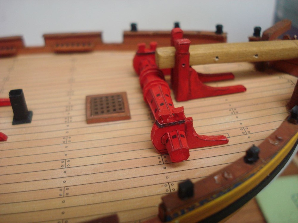
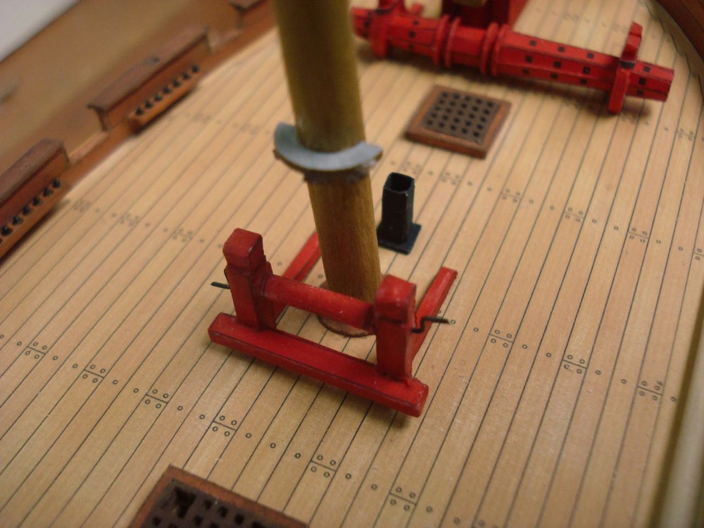
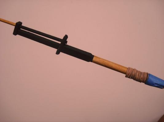
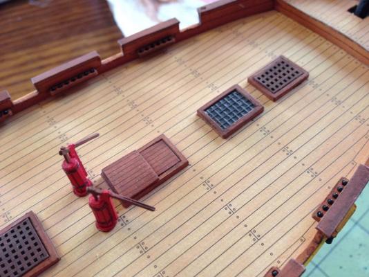
 It's kind of funny writing a paper model build log. It's all about cutting some paper, gluing paper and painting parts. And then in the next step, cut paper, glue paper, paint parts. But then it gets difficult: cut paper more carefully, glue paper very carefully, and with a very steady hand, paint parts. Okay, there's more to it than that, but not much to report except basic progress. I assembled and added what Anatomy of the Ship calls the jeer bits. I couldn't quite gather what the instruction sheet was trying to indicate regarding the windlass handles. The kit includes tiny paper pieces that I would never be able to make use of, so I just used some 26 gauge black annealed steel wire. I also assembled the bowsprit bitts. Somehow the space between the bitts came out the right size to fit the heel of the bowsprit. That, I made from birch dowel. I wanted a square-stock piece, but all I had were dowels. Since the bowsprit was to be 3/16" diameter, I had to work backwards and do a bit of math in order to determine the width of dowel I'd need to start with since the diameter had to equal the widest cross-section of the square heel of the bowsprit. Here's another view of the bowsprit bitts and main windlass. Both are actually only temporarily in place, not glued. For all the bitts, I've embedded straight pins into them for strength. Here's a view of the mast with mast hoops. I used a small piece of blue painter's tape to keep from losing the hoops.

- 121 replies
-
- 13
-

-
Ages of Sail is slated to get a shipment (should be a good sized shipment) as soon as the kit is available. Latest word is sometime in June, but don't quote me on it. No prices given by Amati yet. Maybe in another week or two. I'll make sure that an announcement is posted on MSW as soon as the kits are available for sale. If there is any interest, maybe I can talk the owner into taking pre-orders since release of the kit is imminent. Not sure there would be any advantage to that for anyone except getting the first kits shipped. Clare
-
HMS Alert 1777 by Jaekon Lee - 1/64
catopower replied to Jaekon Lee's topic in - Build logs for subjects built 1751 - 1800
Lee, it's been a while since I've looked in on your build. Wonderful work! I'm half tempted to go and burn my paper model Alert and just follow your blog! Clare -
All very good points. The only comment I'd like to add is to modify Chuck's statement slightly. I believe for the observer, there may not actually be such thing as "too much detail", as long as the details are to proper scale. That is, the details must be physically to scale and visually to scale. The problem with "too much detail" is usually that things stand out too much that shouldn't. Treenails that are too dark or too big look too busy because on most models, they should barely even be seen, some might suggest that they shouldn't be visible at all. But, I agree as to what has already been stated, that it's up to the builder as an artist what level of detail he or she desires to present. Clare
-
Oh yes, can't forget the Optivisor! And, maybe a little bottle of something to calm the nerves...
-
Chris, (LOL) I love that story! It's better than mine. But, somehow, I'm sensing that I'll be able to top it before this build is through...
-
Ron, you don't need a shop for this model, just a cutting mat, knife with blades, a little glue, good desk lamp and 5 bottles of Visine.
-
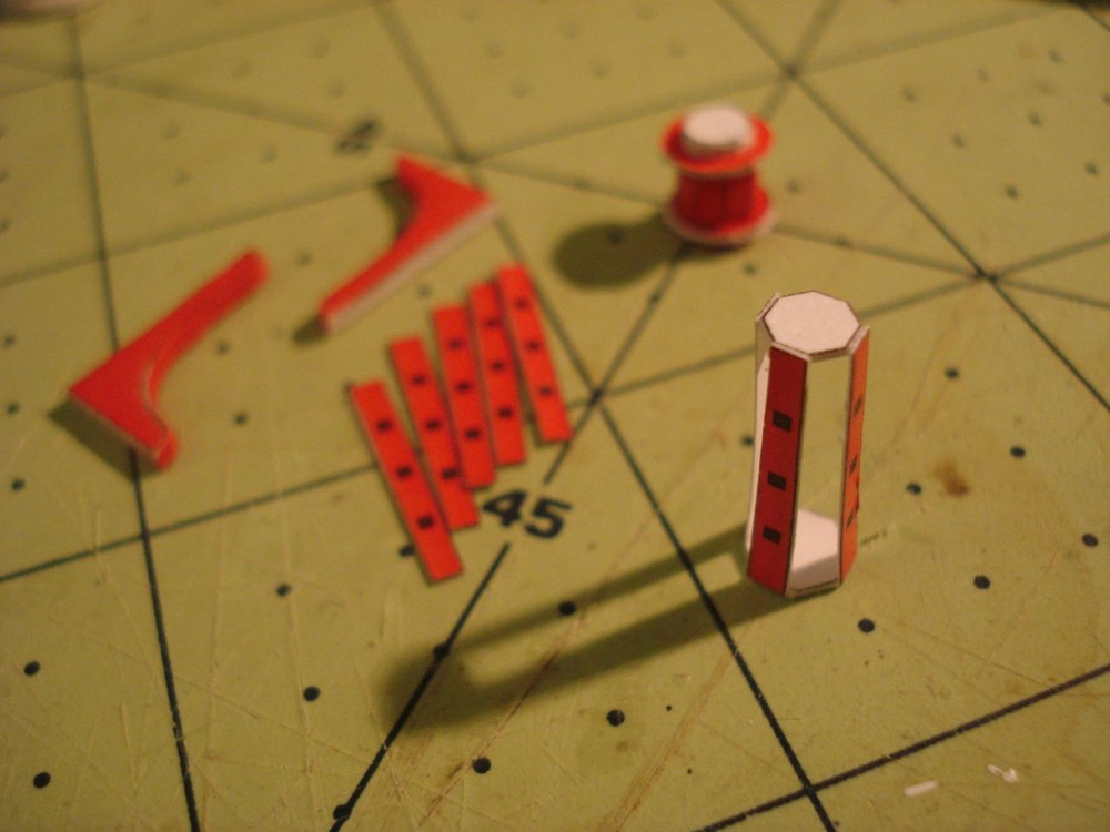
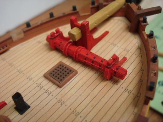
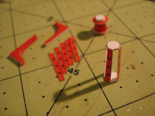
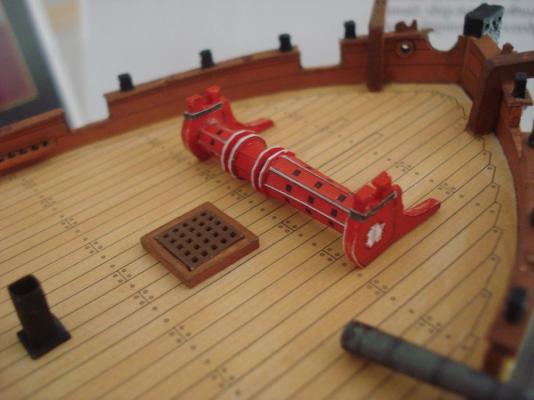
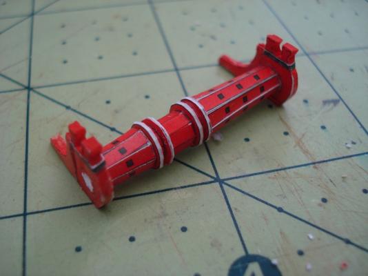
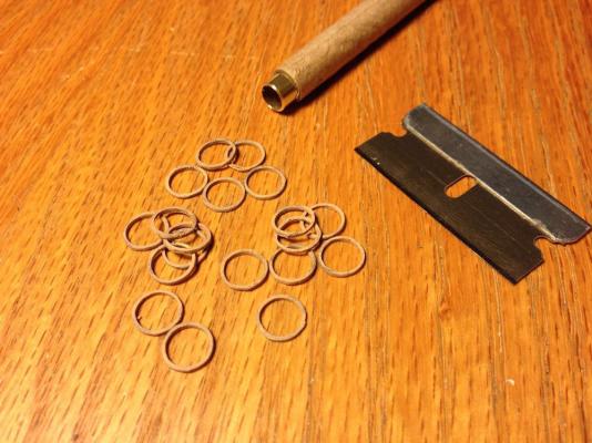
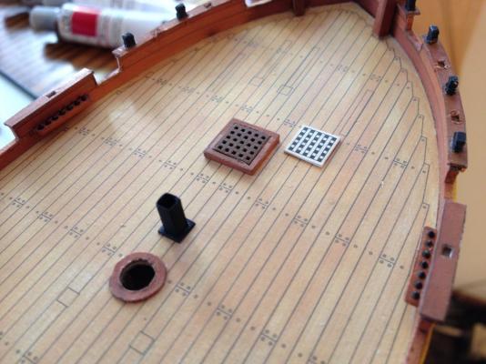
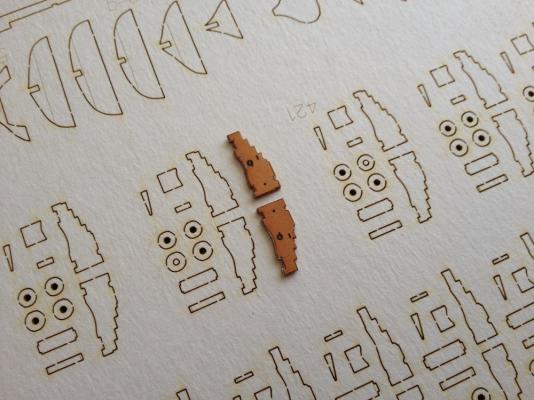
This week, I decided to push ahead and make some more progress. There are so many tiny pieces to cut out! I decided to work on the windlass as that seemed like a good project goal. I got a little ways along and a tiny piece of paper with a bunch of parts on it went missing. I searched high and low, swearing I had just seen it hours before. Next morning, I see it on the armrest of my chair. I must have leaned on it and it stuck to my elbow and got deposited on the chair! I've never had that kind of problem with wooden ship model kit parts. Well, pressing ahead with my report here. I finished the main part of the windlass barrel, which consisted of approximately 31 parts... A 1/96-scale windlass barrel with 31 parts! Am I crazy? Well... maybe. It was a daunting task, but it actually went by fairly quickly and it IS pretty cool that I only needed scissors and knife and some glue... Here's part of the barrel under construction and some other parts too. Sorry about the short depth of field on the macro focus. When you build something, you gotta try it for size on the model immediately. It's a rule. The barrel came out just a tad long, which wouldn't be a problem except that the deck has thin black outlines where the bitts are expected to fit in place. These will show, but the lines won't be very noticeable when it's all done. Here's a closeup of the completed windlass barrel assembly before cleaning it up. And one of the same assembly after some touch-up painting. Again, I'm using the paints sold by Shipyard, which is fairly opaque, so I could paint it on without losing the black printed details. Here's another view of the skylight, gratings and hatch I made last time. I went back and added a piece of fine gauge wire for the handle on the sliding hatch. I was on a roll, so why stop? I'd cut mast hoops from brass tubing on my last model and thought about doing the same for the Alert. In the end, I decided to make my own mast hoops from a piece of a brown paper bag. I did this for another model years ago and it worked out great. So, I thought I'd refresh the skill. I used a piece of brass tubing slightly larger than the diameter of the mast and wrapped the paper around it, applying white glue to it throughout the process. Once dry, I used a razor blade to cut thin rings off. It's been a long time since I've done this, and it took many tries to get even, thin slices. But, I managed to get enough for my purposes. So, what did I learn in paper ship modeling school this week? There are a lot of frickin' little frickin' tiny little frickin' pieces that have be cut. The hardest part is really looking at the work ahead. Yeah, it's like ship modeling that way. But, once you start, all you have to do is cut, cut, cut and cut and cut and then glue. As long as you keep your head down and don't stop to count how many more pieces you need to cut, projects finish up pretty quickly. Clare
- 121 replies
-
- 17
-
-
Hi Ron, Thanks for the info. Ebay is always a comfortable way to buy things from overseas. It's a little more, but is probably beats checking the dollar to zloty exchange rates to make sure you're getting a good deal. Looks like that seller has a few of these. Are you going to be starting a build soon? Hurry up so you can show me how to put this thing together! Clare
-
Marc, Thanks for those latest photos. I think I recognize that model as the Kitamaesen kit that Woody Joe used to produce, but it's been upgraded quite nicely. I love the cargo on the deck, what a great idea! It's actually a shame that they stopped production. I liked the large size of the kit. I think they are trying to make kits that are easier to build, and the older kits are very much more like the kind of kits we'd expect as ship modelers. I have one of their Sengokubune kits, which they still produce, and it's of the older pre-laser cut and less engineered style. It's actually quite a neat kit, but requires a lot more of the ship modeling skills. While less accurate perhaps, the nice thing is that it's a much larger model at about 25" inches. I wanted to get it before it too disappears from production. Because the kit is not laser-cut, I thought it would make a good pattern to build to a larger scale like 1/4" (pardon me... 1/4 sen scale). Marc, as you pointed out, the Higaki Kaisen operated between the large cities of Osaka and Edo (Tokyo) on the Pacific side of the main island of Honshu. I have a DVD that my friend sent me of a symbolic trade journey the Michinoku Maru, a Kitamaesen, made along with Japan Sea coast from Aomori at the northern end of Honshu. That seemed to indicate (gathering this from context rather that from my bad Japanese language skills) that Kitamaesen differed in that they travelled from port to port picking up and dropping off goods along the way. More of a general trade ship. Another friend I play music with likes to study and learn about Japanese music and dance and has often explained how certain kinds of Japanese songs and dances had different names in different parts of Japan, but were related because they were carried by the sailors that travelled up and down the coast. We really don't hear much about these ships (well, not at all in the U.S.) but it appears that they had a significant role in spreading of Japanese culture and the growth of cities in the relative peace and economic growth of Edo period Japan. Bob, hope you don't mind this discussion in your thread. It just seems like th place to bring it up! Is it still early enough in your build to add those interior details? One thing I wanted to add, but never got around to was to make a little Tenmasen, the small cargo boat that was often carried on deck. Don Dressel made one on his model, but I never quite got the hang of the design, though it should be pretty easy to build. PMing you! Clare
- 196 replies
-
- 5
-
-
- higaki kaisen
- woody joe
- (and 1 more)
-
Marc, those are great photos! I myself have gleaned photos off the Internet of the Naniwamaru, the Higaki Kaisen pictured, but not like these. They would have helped answer a LOT of questions when I was building my own. I especially like the cooking hearth and the little shinto shrine in the cabinet. Also, I've never seen the sample cargo in the hold. It's a shame that the museum closed down after they went to all the trouble and expense to build the ship. Hopefully, it's being preserved and not just rotting away in storage. Fortunately, there is another ship called the Michinokumaru that operates on the water in Northern Japan. It's a regional variation of the coastal transport called a Kitamaesen. Essentially the same thing as the Higaki Kaisen. Woody Joe had a kit of a Kitamaesen, but it's now out of production. My understanding is that they hope to re-release a revised version that's of similar quality to the Higaki Kaisen, but I haven't heard of any release dates or other details regarding it. Again, great photos. Wish I could have seen the ship while the museum was open! Clare
- 196 replies
-
- 1
-
-
- higaki kaisen
- woody joe
- (and 1 more)
-
Hooray! Build That Ship
-
Druxey, thanks for the advice. Today, I went right out and bought a can of primer and started spraying everything in site! Well, all the card stock parts that I have issues with anyway... ShipShape, thanks for the tips. I've actually starting thinking of using the artist's protective spray on stuff on the pre-printed parts. I've got some on-hand from old projects, but I actually don't have any issues with the thin printed paper as that paper is coated. In any case, I'm looking forward to seeing that Santa Maria build moving forward again! Clare
-
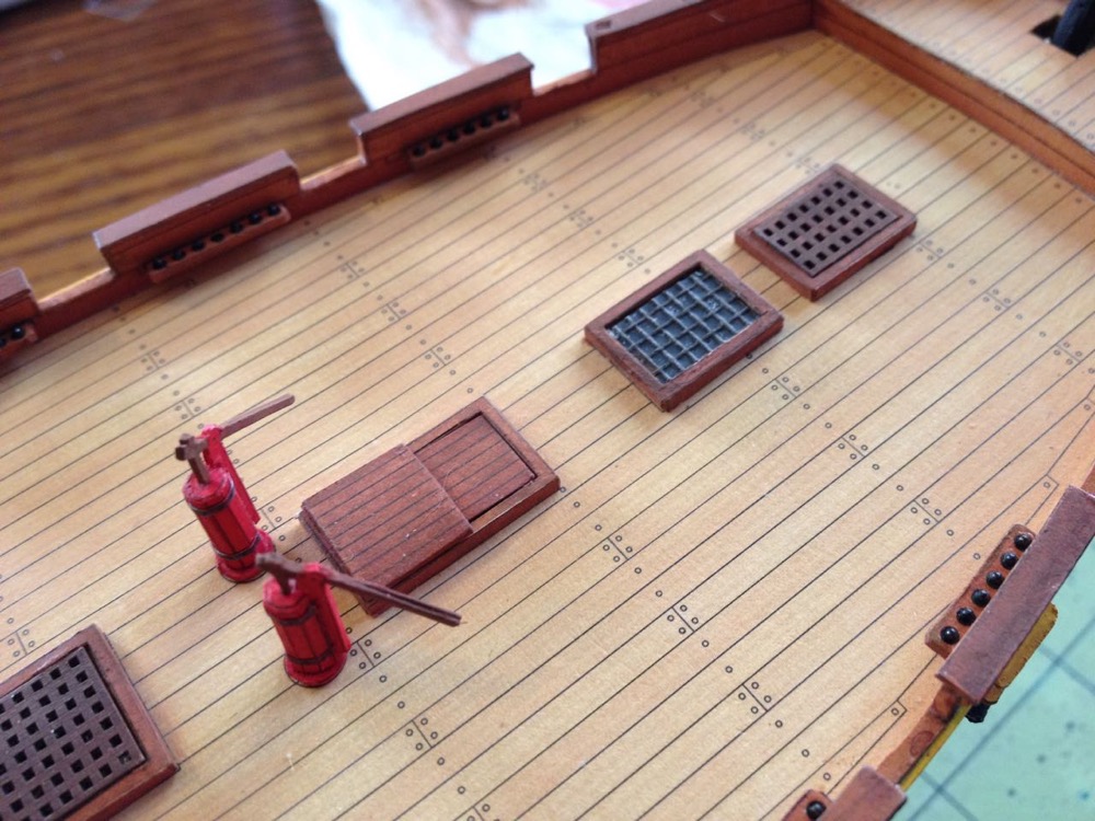
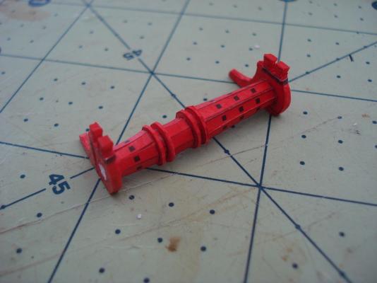
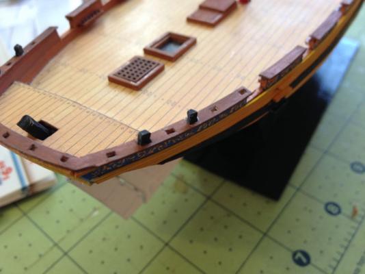
Tony, that's exactly it. You almost have to build with your eyes closed so you can't see what's coming at you next I'm on a roll at the moment it seems. I decided to make a simple sliding type hatch cover for the wardroom companionway. At 1/96 it doesn't have to be that sophisticated. Needed planking, so I printed out 0.25pt lines 1/16" apart. I'm using Adobe Illustrator for a number of other tasks, so it was easy enough to fire it up and make the pattern. I'll probably add some kind of handle, either bent wire or a simple block type handle from paper. The completed piece was painted and set into place. I also found an old screen in the garage. It turns out that the mesh is the exact size I need for the mullion pattern for the companion way over the captain's cabin. I pulled out a bottle of canopy glue, which I bought for another project, but didn't like the way it worked. For this one and the small glass panes, it worked great – Just squeezed a little out to fill in all the holes in the piece of screen material. Once dried it looked perfect, so I cut down to the exact size I needed and dropped it into place. Lastly, I cleaned up the deck pumps after adding the "iron bands". I decided to give them natural wood looking handles instead of leaving them their printed color, which was red. The skylight for the captain's cabin ready to trim and install. Everything in place. The deck pumps were quite a challenge and I'm REALLY glad they're done. I will be burning incense and making offerings to the god of thin CA glue tonight. Also visible is the installed skylight and sliding hatch cover forward of that. Small accomplishment here was adding the stern timberheads. You probably can't see it so well in the photo, but the rudder is also mounted. So, what's next? Good question. I have no idea. Time to look at the kit drawings and get intimidated back into seclusion... But, I'm thinking about cannon barrels (make them from paper or buy or turn them?), deadeyes and chainplates, the taffrail at the stern, and the windlass assembly. Oh, and I noticed that the AOTS book shows two ships boats: A 16' longboat and an 18' cutter. Don't know where these would go, but I also found that the HMS Mercury parts I'm using includes a boat that's just about 16' long. I'll look at the details of that and see if it might be useable. Not knowing where to put it, I would probably mount it as in tow behind the ship. That is, IF I decide to try building it – It seems like a whole project by itself. Clare

- 121 replies
-
- 13
-
-
Ken, The parts I'm having the issue are unprinted, thick laser cut cardstock. That's what Druxey's replying to. I'll be priming both sides. Actually, I regularly have to paint over printed parts. The paint I'm using, the stuff that Shipyard sells, is pretty transparent, which works out kind of nice, unless you're trying to hide some flaw.
-
Chris, have you looked at the 1/72-scale HMS Wolf? It just came out last year and it looks like a much more reasonable project to take on as far as sailing ship card models go. It's also about half the price of the Mercury kit. Druxey, thanks for the tip! I will absolutely be giving that a try. I had the same problem in attempting one of the paper model lighthouse kits that Shipyard makes. The laser cut versions of those (also available in the paper model / cut out and laser cardboard / everything included kits) are reasonably prices and no compound curves to deal with. But, I had the same problem with large paper areas that wouldn't react well when painted with water based paints. Enamel or Lacquer primer okay then? Tony, I'm sorry I missed your question about blackening the ball bearings. I have some stainless steel blackener that has worked quite well on some of the ball bearings. It's called Caswell Stainless Steel Black and it's a thick gel that works terrific on stainless steel. Unfortunately, the formula didn't work very well on these ball bearings. It did darken them a little, but not near enough. I suspect that this is some kind of alloy. I ended up having to roll them around in black paint, and I can't remember now what kind. Having attempted to blacken them though, I think it created a surface took the paint just fine without primer. Well, I wasn't sure what the fate of the Alert was going to be, honestly. But, after working on it yesterday, I'm having fun again. It's just so intimidating to look at a sheet of uncut parts, thinking about all that cutting that needs to be done so carefully. But, once you get going, it's not so bad. Last night I mounted the rudder, added timberheads and mostly finished the deck pumps. Cutting the handle out on that last one was VERY intimidating. Now, I'm starting to think like a ship modeler again and looking at the hatches. The kit doesn't show them, but I think I'm going to cut the holes in the main hatch grating for the anchor cables, and I may have to build my own companion way deck hatch, the sliding type as shown in Goodwin's book on the Alert. I'm also thinking about how I'm going to do the skylight over the captain's cabin. I'll post more pics soon. Clare
-
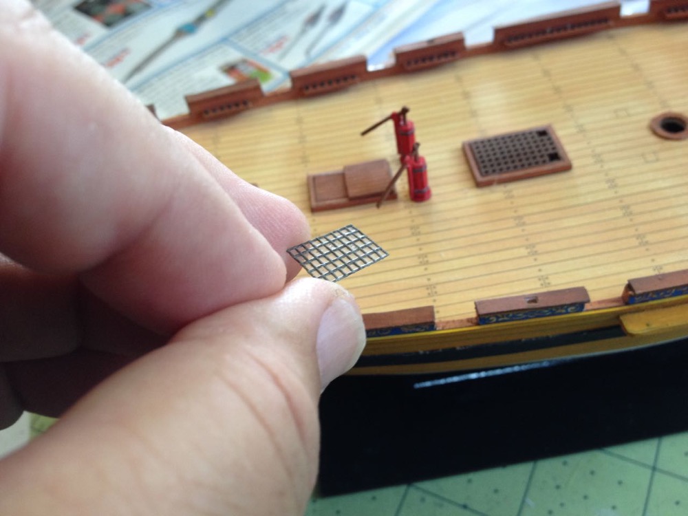
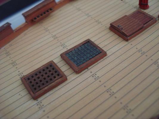
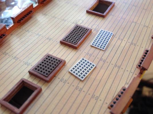
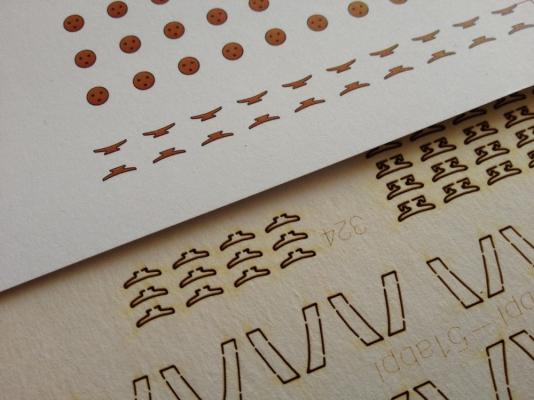
Hi Ken, I ordered direct from GPM. I've order from them maybe 3 times now and it's worked out fine. They seem to have a problem formatting US addresses correctly, but my orders have been arriving okay. Each time, I'd modified the address information I typed in so that the final address looked okay. The last time I ordered from them, it took a little over a month. That's the longest I can recall. I was about to write off the order, but then it finally showed up. On the laser cut parts, the one issue I have with them is that I painted some small parts while still on the sheet. I've been using the paint that Shipyard sells, which is an artist's acrylic. It's water based and it seems to weaken the card stock. So, the small parts fell apart a bit too easily and I lost a few. When I do get the parts free, if they are intact, I touch the parts with a dot of thin CA. That wicks into the part and holds it all together pretty well. Here are a couple photos of the new gratings cut, painted and dry fitted into place. You can see the gratings included in the kit laying on the deck as well. I also found that I could slice off the bottom layer of the grating, opening up the laser etched holes completely. Big improvement. Clare
- 121 replies
-
- 10
-
-
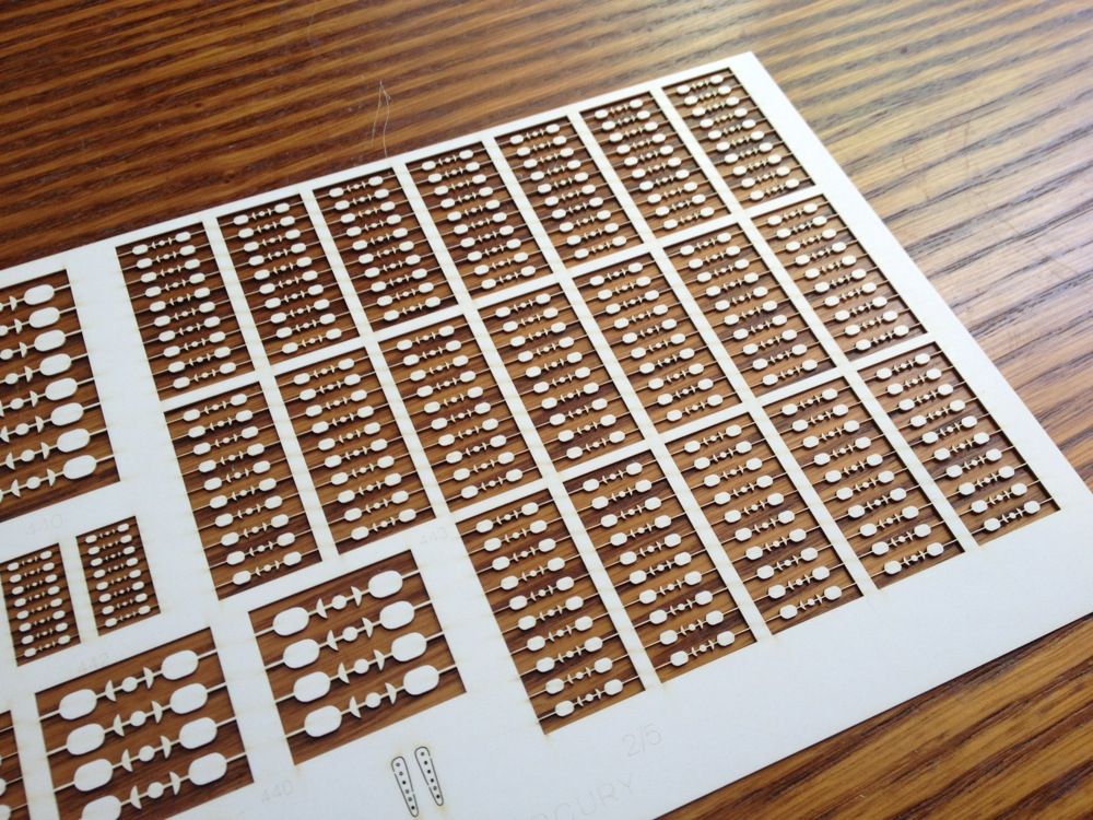
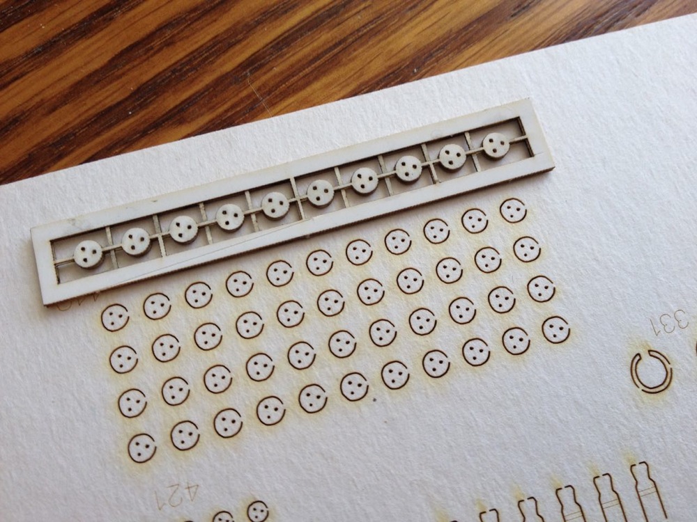
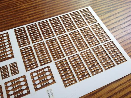
Thanks Slog, Ken and Tony for the kind words and advice. Well, today, I thought I'd take the opportunity to mention that several months ago, I acquired Shipyard's HMS Mercury kit, but not the super deluxe 1/72-scale laser cut version that looks EXTREMELY AWESOME in the box, but the regular 1/96-scale paper model kit. I had to check it out as part of my research into the hobby and also because I just couldn't help myself. In addition, I bought a matching laser cut detail set from GPM. The basic kit includes the laser cut frames, but the detail set includes some very nice features like the gratings, parts for the ship's boats, cleats, blocks and deadeyes, cannon and carronade carriages, and especially nice are the laser cut parts for the stern and quarter galleries. I just couldn't imaging using the printed windows or trying to cut out the frames. Don't worry, I'm not giving up on the Alert and starting the Mercury just now. But this does lead me to some issues I've been having with the Alert. I do periodically pull it out to work on it, but I'm finding that cutting the small parts has been SUPER difficult and it's really slowed me down. I'm doing it, but I'm used to working with wood and being happy with the results. I'm not used to making something that I can't get looking as nice. I've been tempted to cut my losses and go with the 1/72-scale laser cut Alert kit or something. But, then I came up with a nice time saver that may save my project. I looked over the 1/96-scale HMS Mercury detail set and discovered that several items in that set are compatibly with this kit. Maybe that's saying that the kits aren't to precise scale. But, I was going to build the small Alert kit and if I can get laser cut parts that are the same size as those I would otherwise have to cut-out, then I don't care where the scale might be off at this stage. The detail kit for the Mercury cost me about $35 shipped from Poland, and I'm quite willing to sacrifice it for the good of the cause. Turns out that the quarter deck cannon carriages are a perfect match for the Alerts carriages (and the right quantity), the gratings look like I'll be able to cut them to size, some of the cleats are perfect match and there are some others that I think I can trim quite easily. Also, while I've already acquired laser cut blocks and deadeyes of the right size, the Mercury detail set has a ton of these and enough of the smaller ones are the right size to use for the Alert. Anyway, the point here being that if you want to make your life easier with this kit (and probably others too), get one of the detail sets from GPM. It's definitely going to give my project a boost! Clare

- 121 replies
-
- 10
-
-
Hello Puckotred, I too am glad to see you picking it up again! It's such a nice looking ship. I'm looking forward to building this one eventually. Clare
-
Stop taunting us! Where's my issue?
-
Bummer. Looks like he sold 2 of them at the reduced price, then kicked the prices back up again. If you don't mind the Japanese instructions, you can still get them straight from Japan for about $260 from my friend Kazunori at zootoyz.jp. He only does Paypal though. Sorry about that. It was a good deal while it lasted.
- 196 replies
-
- 1
-
-
- higaki kaisen
- woody joe
- (and 1 more)
-
Hi Luke, I have to agree with others that the Midwest kits generally have the advantage of good scale kits with great instructions. But don't get used to good instructions as you will find that very few ship model kits have them – You will definitely have to learn to read and build from plans. As for Artesania Latina kits, 3 of the first 4 ship model kits I built were AL kits. I think they make great starter models and something like the Endeavour's Longboat is probably a good choice, though I don't know the details of that kit in particular. The ones I built had a sheet or two of plans and 4 or 5 pages of instruction. I think a lot of them now have a picture book included that shows you step-by-step how to build the kit. The fittings aren't necessarily the most "to scale" fittings, and if you build more than one AL kit, you're going to start kit bashing really quickly. But, for me, "upgrading" the kits to my satisfaction was half the fun. Clare
-
Hi Bob, hope you're getting settled in okay. I hope you don't mind me interrupting your build log with this, but I just wanted to mention for the benefit of those who are interested in this kit that a local importer (local to me in the SF Bay Area) made some kind of deal last year with Woody Joe to sell some of their kits on Amazon and to provide them with English language instructions. Among the kits are the Higaki Kaisen, Battleship Yamato, large Nippon Maru and others. Problem was that he jacked the prices up by 50% over retail – That's 50% on top of prices that are generally kind of high to begin with. Well, a year later and I don't think he's sold but a tiny handful of kits. With high prices and no marketing, what can you expect? Appears now that he may be dumping them, or at least some of them. I recently noticed the Higaki Kaisen listed at about $238, which is a good sale price, but then I just looked a couple days ago again and it is now listed at $187.36, that's a $230 drop from what he was originally selling at and it is also about $70 less than I've been able to get it for from Japan after paying shipping. He's only got 11 of them, but I haven't seen any of them sell. Not sure how long the price will last, but it's a really good deal, plus you get the English language version instructions. I wouldn't normally plug this guy, as I like to direct business to my friend Kazunori at Zootoyz.jp, but the prices are VERY good and I think these are the last 11 available at this price. Bob, I'll be looking forward to seeing you startup on your Higaki Kaisen build again. Clare
- 196 replies
-
- 1
-
-
- higaki kaisen
- woody joe
- (and 1 more)
-
Sadly, I have nothing more to add, but I'm glad I asked the question! I've been just sitting back enjoying this discussion immensely and am finding it very informative. Clare
-
There are some examples in the book on the Kriegstein Collection, and the authors mention that four of the models in their collection were originally fitted with poles for flags. There is a painting of The Edgar, a 60-gun fourth-rate, 1758, that is shown in the book. It actually shows two ships, each with 5 flags. Both ships are flying the same flag arrangement. Union Jack - bow Admiralty Flag - fore mast Royal Standard - main mast Union Jack - mizzen mast Red Ensign - ensign staff Also two contemporary models of the Greyhound, 6th rate, 1720, and the Diamond, 5th rate, 1723, show the exact same flag arrangement. I did note too that the authors wrote a good paragraph about flags at launching. Nothing revealing, but they do mention that launchings were festive events with royalty occasionally present. Do you suppose the Royal Standards are flown because royalty was present? I assume the red, blue, or white ensigns would be flown depending on which squadron they were assigned to. That seems to be consistent across all examples. The Union Jack seems mostly consistent too. Druxey, that foremast flag on the Royal Sovereign doesn't look like a Blue Ensign to me. Yet, it's not quite a Union Jack. Looks like a St. George's Cross on a blue field. Not sure what that would mean. Clare