HOLIDAY DONATION DRIVE - SUPPORT MSW - DO YOUR PART TO KEEP THIS GREAT FORUM GOING! (Only 13 donations so far - C'mon guys!)
×

catopower
-
Posts
1,868 -
Joined
-
Last visited
Content Type
Profiles
Forums
Gallery
Events
Everything posted by catopower
-
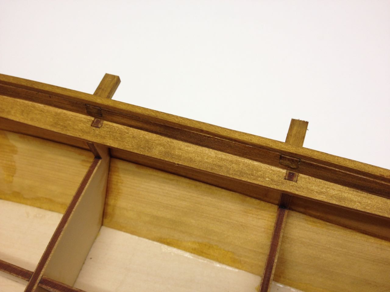
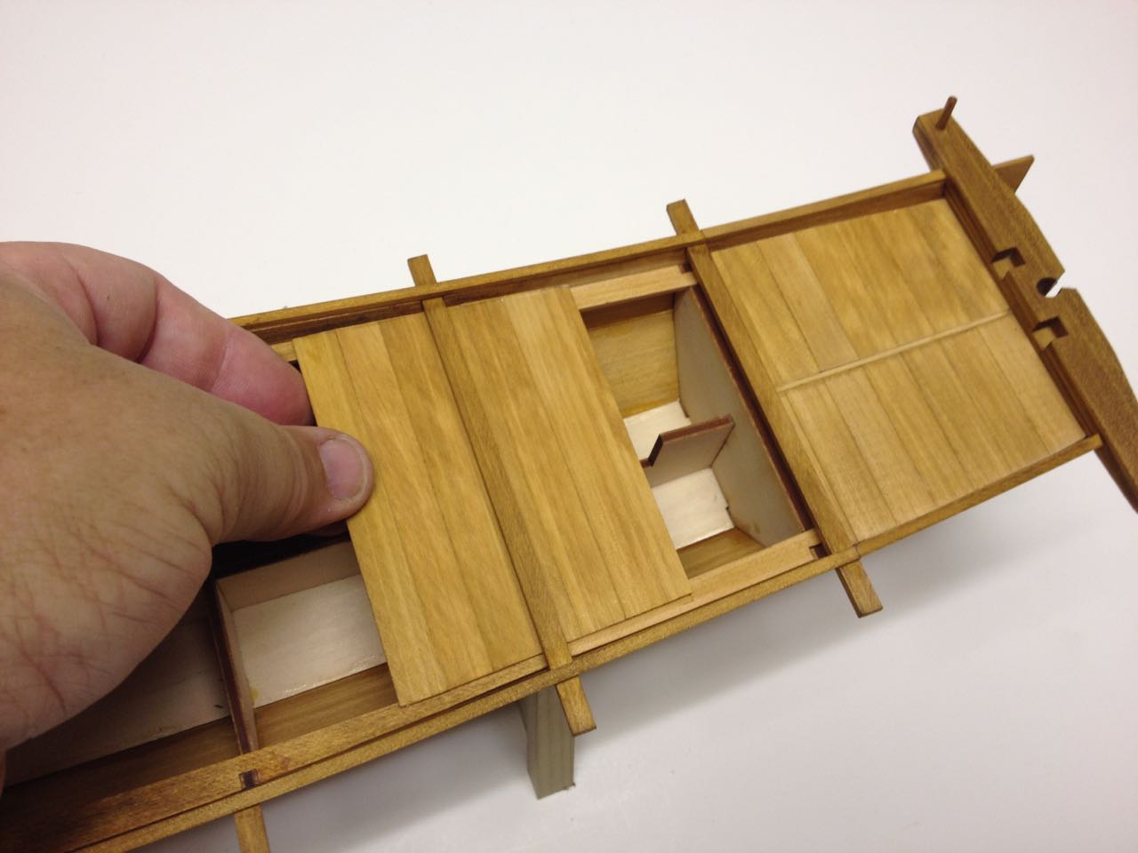
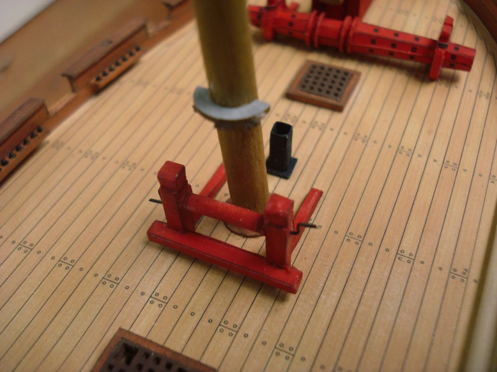
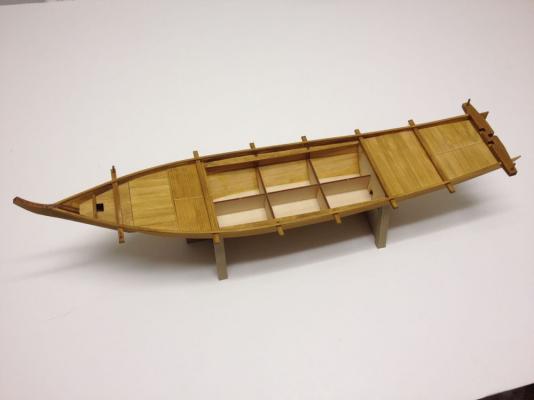
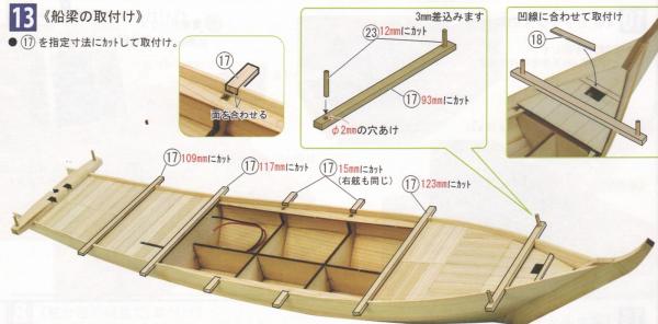
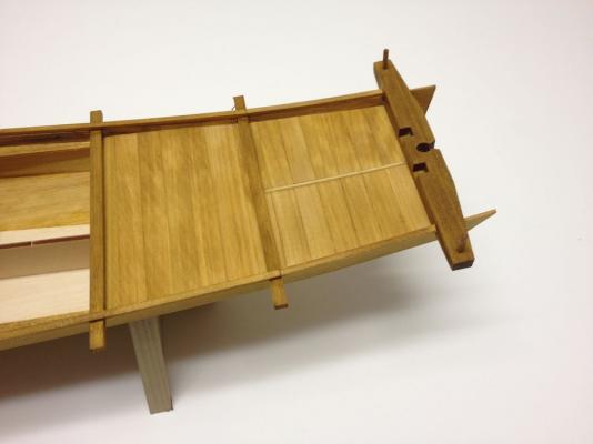
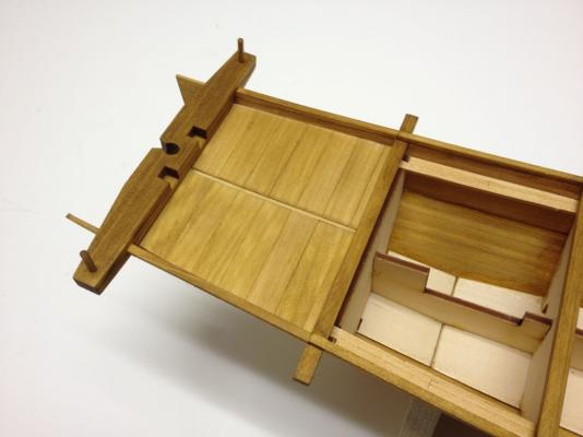
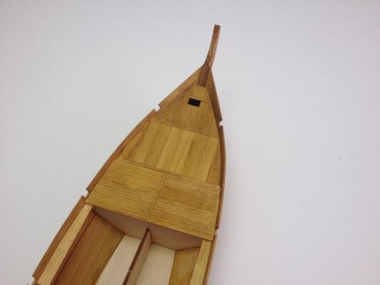
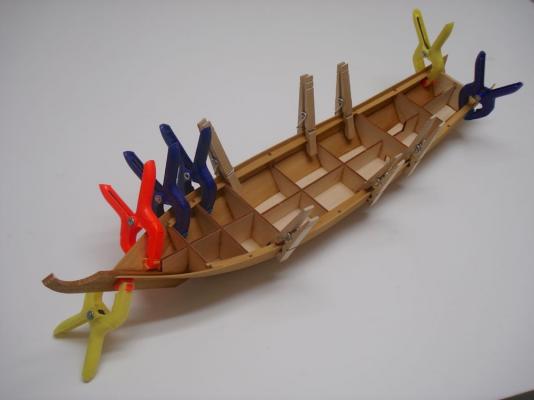
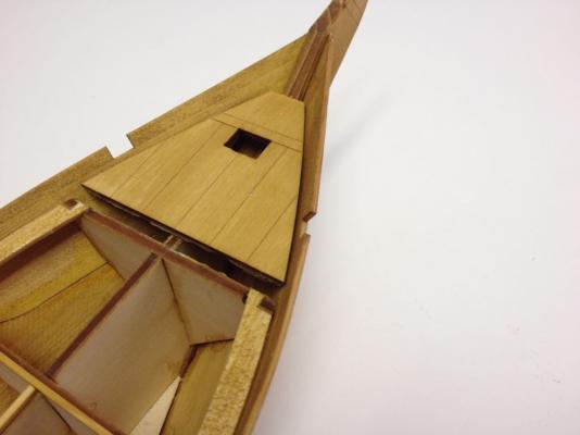
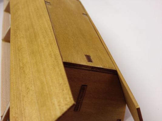
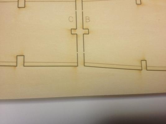
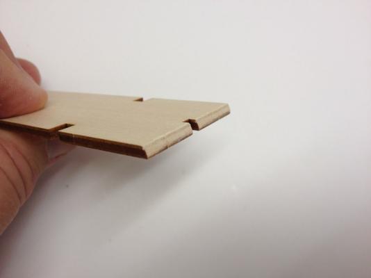
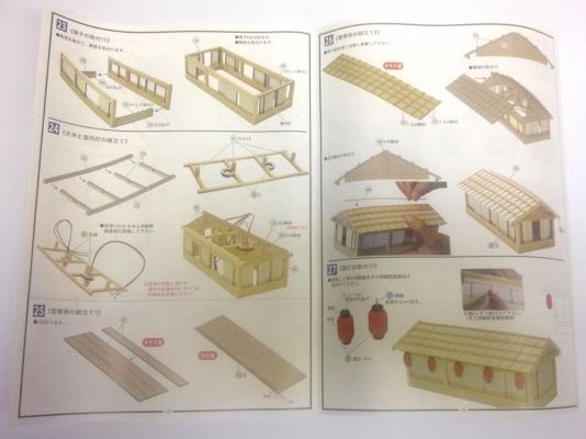
 Now, getting back to boat construction. The deck planking is complete since the center section is the area for the deck house. The next step is to cut and fit the beams. On a real traditional Japanese boat, the beams would be mortised into place. On the model, they're not really structural members and just glue in place in the laser cut notches of the upper planks. If the upper planks were mounted too low, the beams wouldn't fit properly as there is little clearance for them once the deck planks are installed. The beams are among the included strip wood supply, so they have to be cut to length. This was a good opportunity for me to use the Japanese hobby saw I got from Zootoys. The saw isn't cheap, but if you're buying a kit from Japan, it shouldn't add much to the shipping cost since it's so light. This is the first Japanese saw I've owned and it is a treat to use. Unlike Western saws, Japanese saws cut on the pulling stroke. This keeps the cut very straight and allows the saw to be very thin. This is, in fact, the thinnest hobby saw I've ever seen at only 0.1mm thick. All in all, the cuts are very straight, very quick, and very clean. This photo may make the saw look a lot bigger than it really is. It's just under 8" long and is very light weight. Anyway, cutting and fitting the beams was very simple. The short beams were a bit more of a challenge since the inside edge is sanded flush. Below, you can see how the battery cover section of the deck is left so that it can slide in and out of place. I recommend removing this section while working on steps 13 and 14 to better avoid accidentally gluing it into place. Note that all the photos show the caprail in place. That's actually step 14. Basically, full length strips are shaped to fit at the stem, but the won't be long enough to reach the full length of the boat. At the aft end then, short pieces are put into place. The caprail fits so that the inner edge is flush with the hull planking. This is a very straightforward part of the build. Roughly Translated Text (some of this required a little more interpretation to make sense): Step 13 Installation of Beams • Cut and install 17 to dimensions shown and install. Short beams should be mounted flush with the inside of the hull planking Cut a part 18 to fit the laser cut area at the bow deck as illustrated. Fit of short beams on starboard side is the same as on the port side. One line I can't quite translate exactly, but can only interpret. On Bing Translate it comes out as: "3 mm difference between narrow the scope" On Google it comes out as: "3 mm Masu Plug" What do either of these mean? This is a straight forward step where a 2mm hole is drilled in either end of a beam and a 12mm long dowel piece is fit into them. The exact positions can be viewed on the plans. The only thing that I can figure about the “3 mm” reference is that 3 mm of the dowels will fit into the beam. I should point out that Bing seems to translate better than Google – At least for Japanese text. The above text makes more sense with the instructions illustrations. Again, with permission from Woody Joe. Step 14 Installation of Deck Edge (Caprail) Bend pieces to shape of hull. Please add short sections at stern. (Japanese instructions are quite polite and often say "please") Align inside edges of rail to inside of hull. The model is looking more like a traditional Japanese boat now and I'm really finding that I am enjoying this build perhaps even more than the last one, which had sails and oars. This one, somehow feels culturally significant, if that makes sense. Clare


- 106 replies
-
- 11
-

-
- Japanese boat
- Wasen
- (and 2 more)
-
David, I agree with CWG that this is not the SeeAdler kit. I don't know what kit it is, if it's a kit at all. The tall lower masts suggests to me that this is probably a 3-masted schooner. You can probably finish it up that way rather quickly and easily. Clare
-
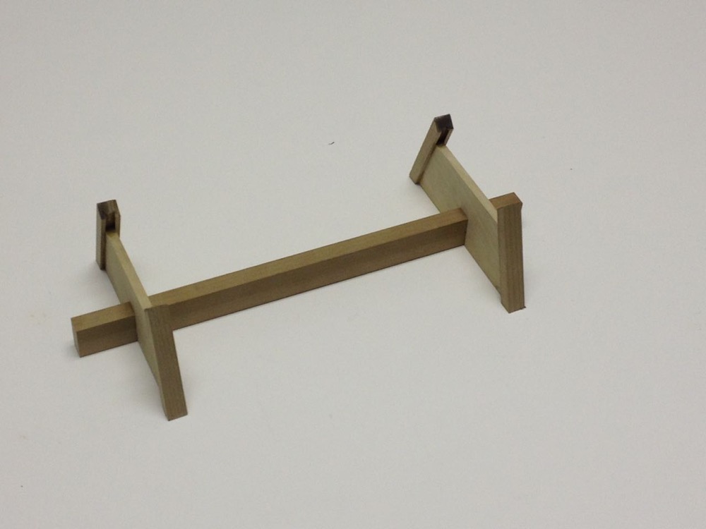
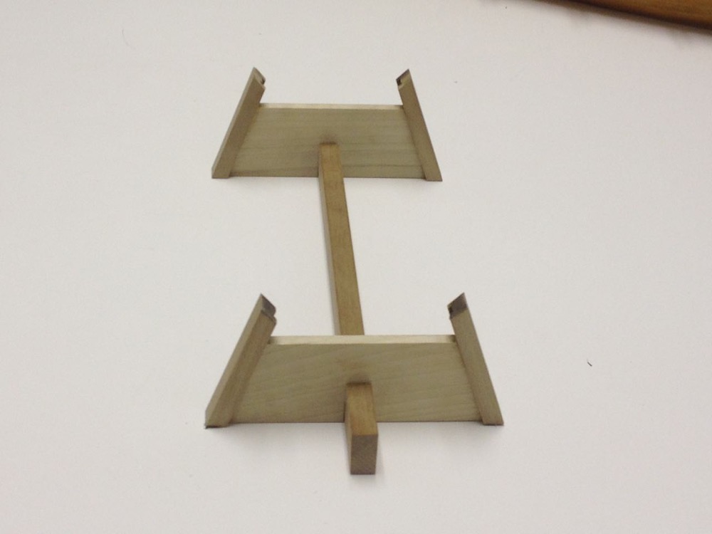
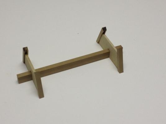
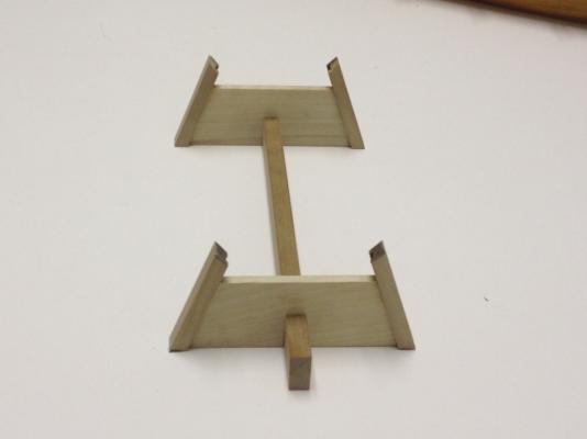
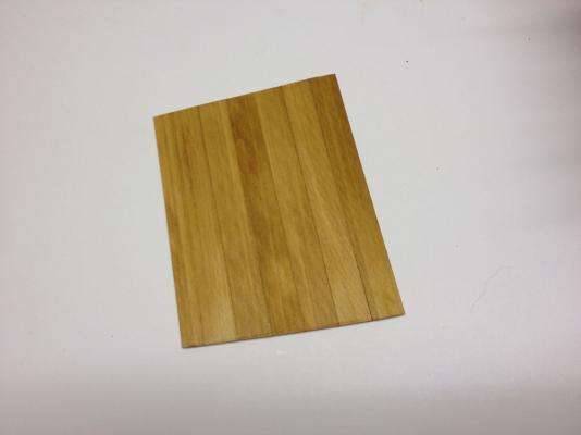
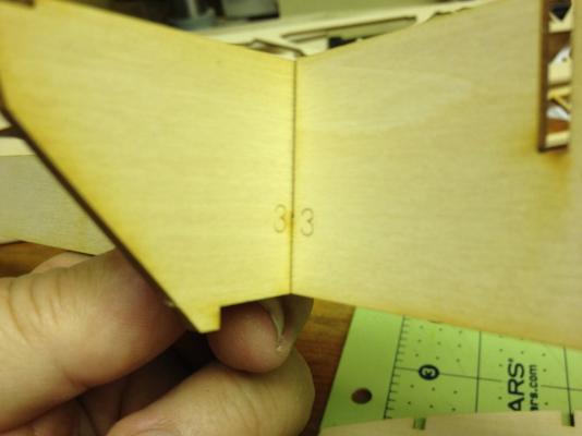
In my last model photo posted, you can catch a glimpse of the stand that is included with the Woody Joe kit. This is a nice feature that is included in all the Woody Joe kits I've owned. The stands are all made of Japanese Magnolia, called "Ho" in Japanese. It's kind of a light grayish brown color with very little grain. It's a somewhat plain looking wood. But maybe that keeps your eye focussed on the model and not the stand. On other models, I've drilled the stand out to add a brass rod that runs into the bottom of the model, helping to keep it from sliding around. I haven't gotten to it yet, but I think I will use a piece of brass tubing in one of the stand pedestals to allow wiring to pass on into the bottom of the model. This step really requires not translation or explanation. I think every ship modeler understands that the top ends of the supports need to be tapered to fit the hull of the model, and the base of the supports need to be trimmed to sit flush with the bottom of the stand. Translated text: 12 Stand Assembly • Stand is assembled to fit the hull. • Trim the hull supports, parts 33, to fit the shape of the bottom of the hull. Then, trim to bottom of the supports to fit flush with the bottom of the stand. Note: See full sized drawings for mounting location of hull on stand. Cut to fit the lower hull planking. Bottom of hull rests on the stand. Cut the bottom of the supports. On the name plate, I decided to try to fill in the text. The plate is a piece of wood and the text is laser-etched into it. The etching is darker than the rest of the wood, but it doesn't stand out all that much. So, I tried to seal the wood with Danish Wood oil. I didn't know if this would actually seal the wood, but it seemed like it should give a couple good coats. After giving it time to dry, I used some black acrylic paint and filled in the etched areas as cleanly as I could. Some paint did get out of the flat surface of the name plate and I had a difficult time cleaning the excess paint off completely. After a couple applications of black paint had dried thoroughly, I lightly sanded the surface of the name plate to take off any smudged paint. This worked well enough, though not as cleanly as I would have liked. People who can read Japanese can probably make out the characters. People who can't read Japanese can't tell what's readable and what's not, so all is probably well! No photos of the nameplate yet. Also, I haven't added the wiring tube or brass rods to the stand yet. I figured I'd wait and give myself time to think the wiring process through. Clare
- 106 replies
-
- 8
-
-
- Japanese boat
- Wasen
- (and 2 more)
-
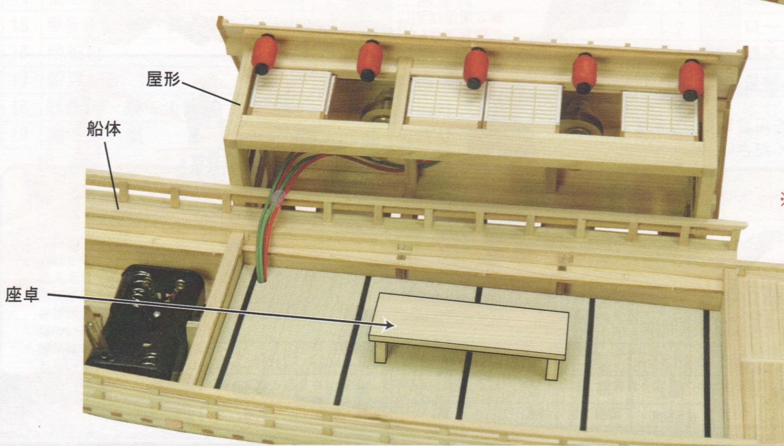
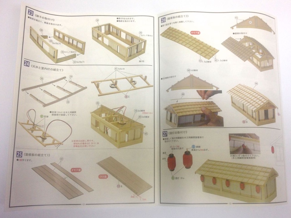
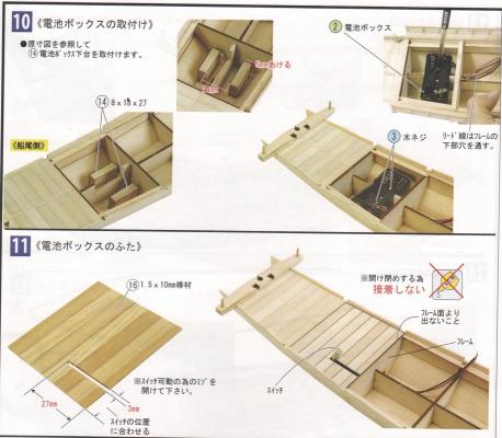
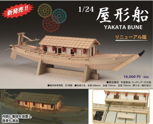
The Yakatabune kit is designed with internal lighting. Kind of separates this model from some of Woody Joe's other models. The lighting is simple and consists of a pair of small incandescent bulbs powered by a pair of AA batteries. I considered a few possibilities with this. One possibility is just to leave the lighting out of it, since the real idea behind building this model is to accompany a couple other models for a bank window display. The lighting wouldn't be noticeable and certainly wouldn't last long on a pair of double-A's. Also, the battery switch is made to stick up out of the deck and I don't like that idea. Another possibility is to use LEDs, light up the interior and make new hanging lanterns outside the deck house with LEDs in them. Problem with that is all the wiring and the fact that I don't necessarily want to light it up like a Christmas tree. The last option I considered is to just replace the bulbs in the model with LEDs, which should give longer life, and not require too much wiring. In all cases where there is lighting, I wouldn't want to go with a battery pack. So, I'll have to do some planning out of the wiring to use an external power source. Steps 10 and 11 mostly deal with the battery pack, so I skipped most of this in my model construction. However, the kit text is roughly as follows: 10 Installing the Battery Box • Referring to full scale drawings, install Part 14 stands for battery box. • Wire leads pass through hole in bottom of frame There are a couple parts labeled • Miscellaneous Part 2, Battery Box • Metal Part 3, Screws This step requires gluing a pair of support blocks to the floor of the boat, running the wire leads forward through the hole in the bulkhead, and screwing the battery box into the support blocks. 11 Installing the Battery Box Lid • Do not glue battery cover in place. This needs to be free to open and close. • Deck/Battery Cover should be long enough to cover the edge of the frame (frame 6). • Cut a slot in the deck 3mm wide and 27mm long to allow movement of the battery switch. You'll need to refer to the position of the switch to make sure the slot in the cover lines up with it properly. You can see here that Woody Joe now puts a nice big icon with a glue bottle crossed by a red "X" to indicate to not glue a part. This was one weak point on their Higaki Kaisen instructions that I wrote to them about. I don't know if I was any influence, but this is a big improvement for those who don't read Japanese AND for those who just don't read instructions very closely! Here's the deck piece that would have served as the battery cover. I'm leaving it removable so I can work on wiring. And here is the battery cover deck in place. It's a bit of a pain trying to slide it out as it's hard to get a grip on the deck without marring it. I'm probably going to glue something to the edge of the cover so that I can get a better grip without causing any damage to the wood. And, now that I think about it, with that battery switch, I'm not sure how that would work. If it's sticking up through the slot, you can't slide the cover out. If you push it into the slot so that you can slide the cover off, how do you reach the switch to pull it back up into place once the cover is back on? Maybe I'm not seeing something here. But, since I'm not installing the battery pack and switch anyway, that's a question I'll leave to another builder. My latest thought is based on a suggestion someone made when I discussed the adding of details to the model. The idea is instead of putting in two ceiling lights, which would not have existed in an Edo period boat, putting in a couple large floor lanterns. These would be box-like structures that would probably sit in the corner of the room to provide light. This avoids having to run wires into the ceiling. This also should make the deck house more easily removable if needed. I can try to make the lanterns and mount LEDs in them quite easily. The resistors for the LEDs can then easily be mounted just underneath the floor. Here's a look ahead in the instructions, so you can see how it's intended to work. The lanterns should be similar to these modern made floor lamps that I found on the Internet. Not sure yet what level of detail I want to go to yet, but I'm developing some ideas. Clare

- 106 replies
-
- 14
-
-
- Japanese boat
- Wasen
- (and 2 more)
-
Thanks Gary. Will be good to meet up with you and the guys on Saturday. I wasn't actually planning to bring the Yakatabune because Kent asked me to bring my HMS Victory and I wanted to keep up to date on that. Also, I brought my completed Hacchoro model last time (or the time before) and this looks pretty much the same right now. Buck, the more models, the better! Right? Clare
- 106 replies
-
- 3
-
-
- Japanese boat
- Wasen
- (and 2 more)
-
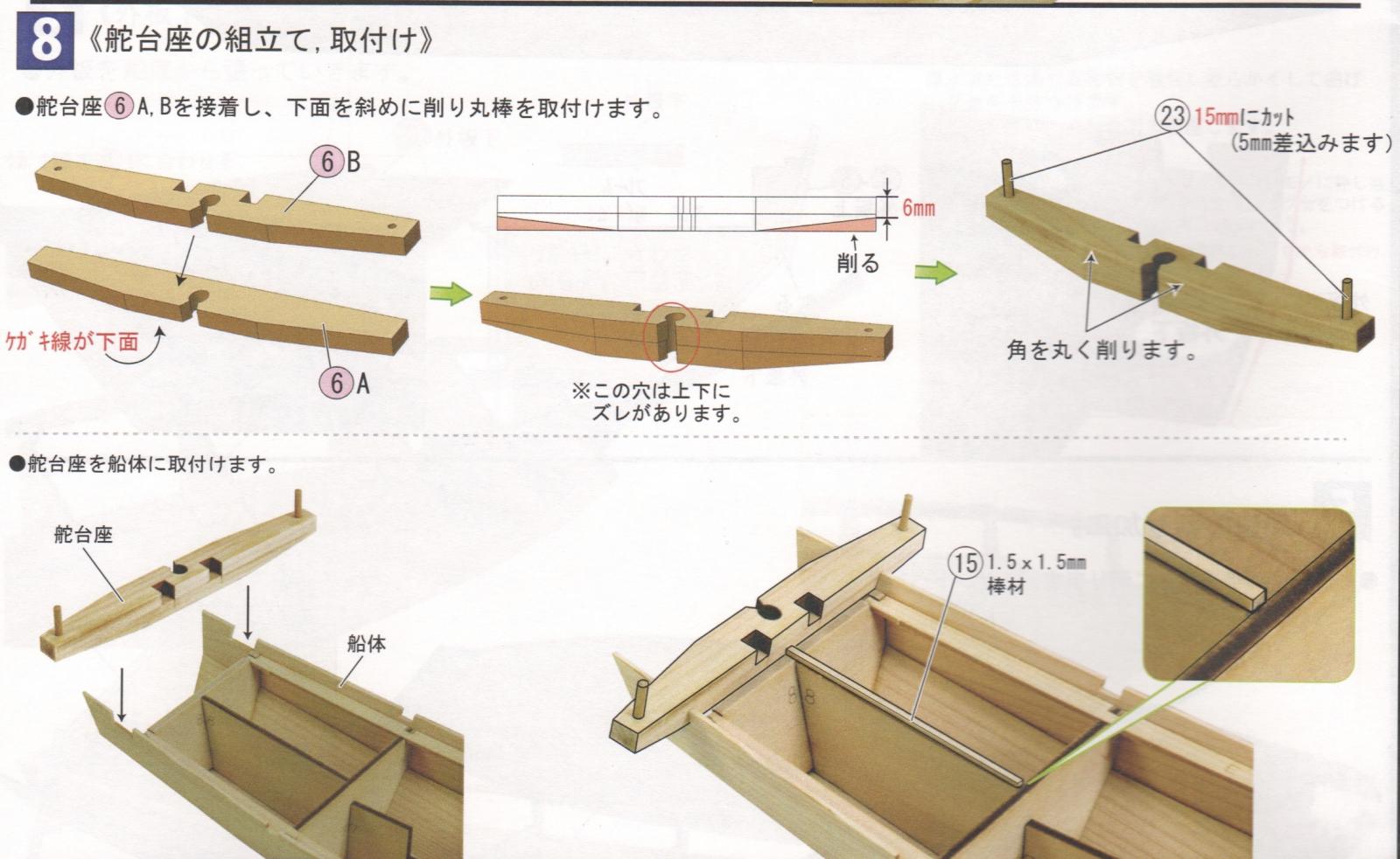
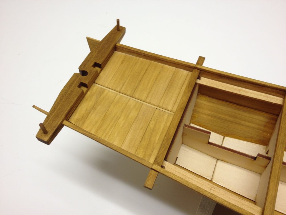
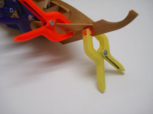
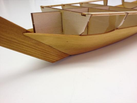
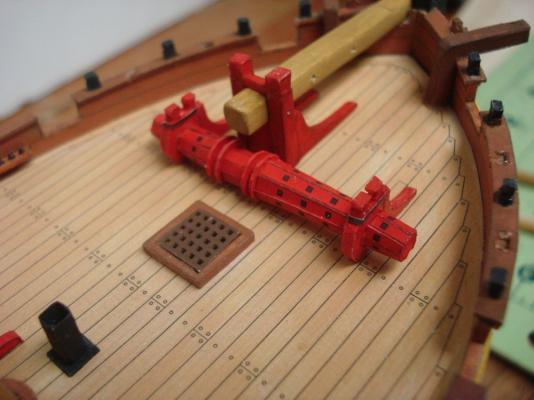
A feature that seems very common to all the traditional Japanese boats I've worked on so far (4 of them) is something called a Kajidaiza (kah-jee-die-zah). This is a heavy beam at the stern which is notched for a rudder. I've seen other Japanese boats that has the beam with no rudder hole, but I don't know if it has the same name. The name apparently translates to "rudder pedestal." There are no gudgeons and pintles on traditional Japanese boats. There is no fixed mounting of the rudder at all. Rather, the rudder is held up in place by ropes. The ropes are also used to raise and lower the rudder as needed. They can be raised when operating in shallow water or when beached, and they can be lowered and even fixed in place to act as a keel. On the Yakatabune, I'm not really sure what purpose the rudder serves. These boats were usually propelled by a single oar or a combination of the oar (sculling oar) and long bamboo poles to push along the shore or shallow bottom. Many images of Yakatabune show no rudder. Well, this one has a rudder. Steps 8 and 9 are all about the Kajidaiza and the aft section of deck planking. Translated Text: Step 8 Assembly and Mounting of Rudder Pedestal • Glue rudder pedestal parts 6 A and B together so that the rudder holes line up. • The scribe lines on 6A should be on the bottom. • The top rear edge of the pedestal should be rounded slightly. • Taper the bottom of the pedestal according to the diagram. • Cut posts 15mm long (inserts 5mm into hole). • Attach the rudder pedestal to the hull Step 9 Installing the Aft Deck • Rough cut strips 16 and glue together, then trim to fit deck. • Cut and install 1.5mm x 10mm strips Not much to say about the aft deck except that it needs to stop right at the aft edge of bulkhead number 7. This is because the deck panel just forward of this one needs to be removable, and the bulkhead will give it better support when in place. One thing I'll mention is that the posts on the ends of the rudder pedestal often are shaped with a taper and a kind of a faceted ball shape on the end. I haven't been able to replicate this detail on my models, though I eventually hope to. If you look around the Internet, you can probably find photos of what I'm talking about. They appear on the full-size replica of the Higaki Kaisen. In my photo here, I actually had progressed ahead a few steps and you can see deck beams fit into place, and the cap rail glued on top of this. Clare

- 106 replies
-
- 10
-
-
- Japanese boat
- Wasen
- (and 2 more)
-
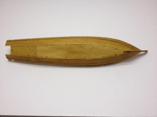
A quick update... It's time to start deck planking. Translated text: Step 7 Installing the Forward Deck - Pt 2 The only full line of text in this section is repeated and simply says: Trim the outside edges to fit against the hull planking. Deck planking on these Japanese boats varies with some planks running fore-and-aft and others running athwartship. Unlike the Hacchoro, thin strips that divide the panels of planks are installed first. Planks are glued together to form panels according to the plans. These are then trimmed so that their edges fit the shape of the hull. Because I shortened that pre-cut deck piece in the last posting, I had to compensate by making the next section of planking just a tad longer. I first glued the dividing strip into place, then marked a piece of planking stock to the proper length. I used that to set up my Chopper III and cut the necessary planks to size. The rear set of planks appear to extend beyond the edge of bulkhead 3. I'm not sure why that is, but I expect I'll find out soon enough. Clare
- 106 replies
-
- 9
-
-
- Japanese boat
- Wasen
- (and 2 more)
-
HMS Alert 1777 by Jaekon Lee - 1/64
catopower replied to Jaekon Lee's topic in - Build logs for subjects built 1751 - 1800
Incredible work Lee! Well, if I can get up enough momentum, I'll have to finish my paper model, so I can take inspiration from your work and get back to wood. And there's a LOT to be inspired by here – Not that I could ever achieve anything close to what you've done! Clare -
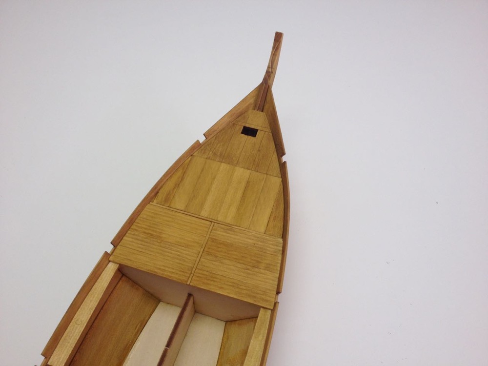
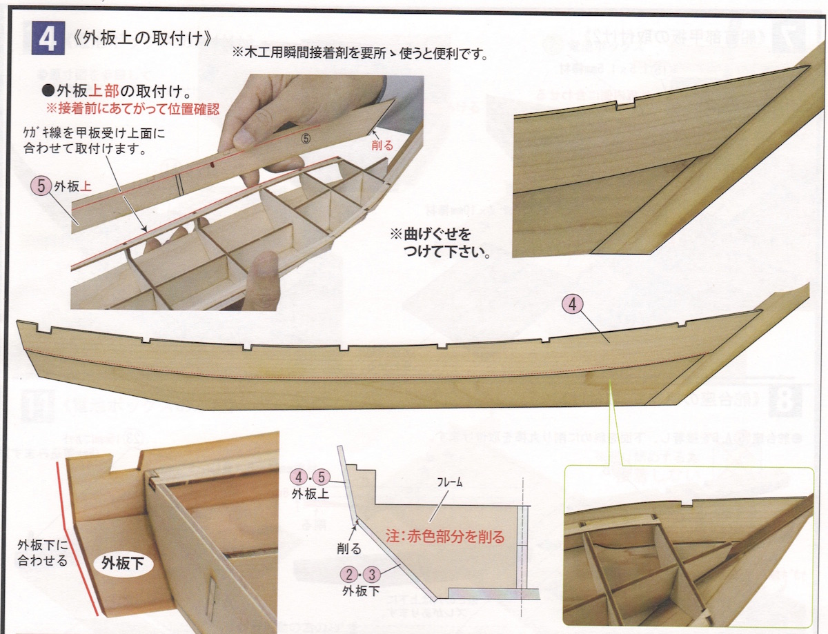
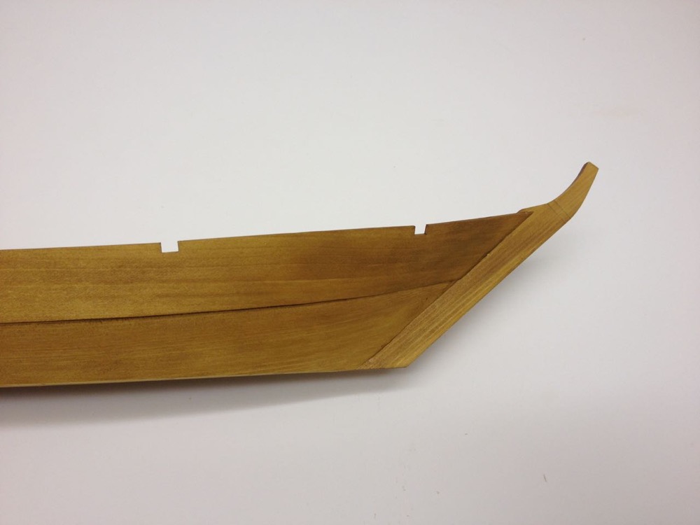
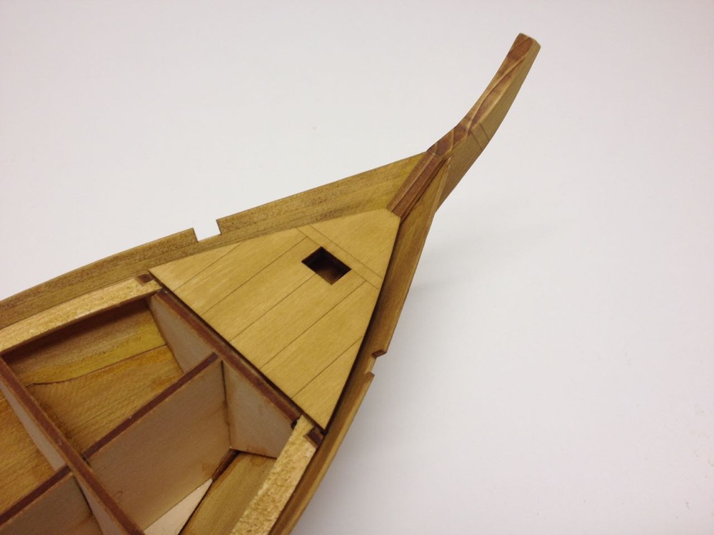
The following is the actual text translation using the online OCR software I mentioned, use of Japanese character input system to make corrections, and a combination of both Google Translate and Bing Translate to find the best translation. After that, the English translation has to be interpreted to make normal, understandable sentences. It requires a lot of interpretation still. The system mostly works, but it's kind of a lengthy process. Luckily, there really isn't a whole lot of text to translate, and this isn't a difficult kit. Probably the most difficult task is correcting the OCR errors. Step 4 Attaching the Upper Planking • Bevel the bow edge of the upper planks (laser cut parts 4 and 5) using the laser-etched lines as guides. • Before gluing the upper planks in place, make sure the laser-scribed alignment marks line up with frame 4, also align the horizontal scribed lines with the top edge of the deck supports. • The upper edge of the lower planks must be beveled so that the upper planks lie flush with the frames. • Note that the upper and lower planks should line up at the stern. Images posted with permission from Woody Joe. The text in the bottom center images simply tells you to cut/file away the red area, which is at the upper edge of the lower plank. The first trick here is that the forward ends of the planks have to seat nicely to the stem. There is no rabbet. The images show the plank to overlap the lower plank, but mine don't really overlap, rather they kind of line up with the lower plank. This may simply be an error on my part, but I had the same thing happening on my Hacchoro model. Anyway, it's necessary to get everything in alignment before gluing. I used clamps and rubber bands to keep things in place first. Then, when I was happy with it, I used CA glue to lock it all into place. The most critical part is to make sure the notches at the top edge of the upper plank are lined up with each other. If these are off, then all the beams will be askew. Image is from my Hacchoro build. Another of my Hacchoro build showing clamps at the bow. The Yakatabune's bow. This step and the previous one are probably the hardest steps in the build. Certainly that was the case for the Hacchoro kit, and probably the same here. One thing is certain. It takes me a lot longer to write these posts than it does to complete the steps, so I better keep pushing along here. Steps 5 and 6 are very simple. Step 5 is to sand the bottom flat and Step 6 is to add a pre-made deck piece at the bow. Translated text: Step 5 Finishing the Bottom • Use a sanding block to trim down the edges of the bottom plank This is a very simple and straight forward step. There are a number of tabs that show through the hull bottom. But, being that the bottom is flat, they're going to be out of sight. Translated text: Step 6 Installing the Forward Deck – Pt 1 • Test fit the bow deck piece, laser cut part numer 1-D. Bevel the edges where it comes in contact with the stem and hull planking. • Note that the bow deck piece will sit about 1.5mm above the frames and deck support strips. Now, this is where I ran into an issue. Because this little deck piece is added AFTER the planking is in place, there's no guarantee that it will fit perfectly in place. Were I to do this again, I'd drop the piece into place, maybe even temporarily, to help figure out the run up the upper plank. As it is, there was a gap along the edge of this deck piece. Now, this isn't a highly detailed model and is just designed to look nice on the shelf. So, if this happens to you, nobody but you is going to care. I had a similar issue on the Hacchoro model, but I just ended up rebuilding the deck piece, making it from the same planks as the rest of the model. Not sure why this area is different. This time, I simply trimmed the forward edge back until the sides made better contact with the hull planks. Not ideal, but I was just trying to do something different than last time. As a result, I will have to compensate in the next step, to allow for the shortened bow deck piece. This was an easy fix, and is probably about as difficult as this model gets. Up to this point, the construction of this kit is pretty much identical with the Hacchoro. Looks like the construction will start to vary with Step 7. Clare


- 106 replies
-
- 10
-
-
- Japanese boat
- Wasen
- (and 2 more)
-
Hi George, The Higaki Kaisen is certainly the most complicated and most interesting of Woody Joe's traditional Japanese boat kits. I usually recommend one of the simpler ones first. But, the Higaki Kaisen is also the only one with English translation version available. It was put together by an importer who worked out the details with Woody Joe. The kit is over priced, but it is available from Amazon prime. Once in a while, there seems to be a price drop, but I think as soon as one sells, the price seems to immediately be set back to "normal". There's a link here: Higaki Kaisen on Amazon Prime Note that this is the only Higaki Kaisen kit listed on Amazon that has English language instructions. I've been in contact with the importer before and tried to tell him he was pricing himself out of the market, but he seemed to feel he needed to sell them at this price in order to cover shipping and all. I may try contacting him again as last time was more than a year ago. Clare
- 106 replies
-
- 2
-
-
- Japanese boat
- Wasen
- (and 2 more)
-
Hi Grant, Mark, George, glad to have you aboard for the Yakatabune build! George. Regarding online translation, it's tricky. As Mark points out, you have to scan the instructions and then pass the image through OCR software or Optical Character Recognition. The software takes the image and turns it into text. Specifically, you need Japanese OCR software which turns it into Japanese text. This can then be passed into Google or Bing Translator to give you results in English. There are problems with this depending on the OCR software. It doesn't work 100%. And, if you have no way of correcting the Japanese text before sending on to Google, then you get some pretty weird translation. FYI, I do this now so I don't have to bug any of my Japanese friends or relatives for help. There is a free Japanese OCR service online here: http://www.i2ocr.com/free-online-japanese-ocr You just upload the scanned image and it converts it into Japanese text. Again, it's only maybe 80%-90% correct. I know enough Japanese to recognize where the OCR software screws up. Interestingly enough, it screws up the simplest of Japanese characters, but tends to get most of the more complicated stuff. Now, on my Mac, with an external trackpad, I can actually use a character input system that will recognize strokes drawn on the trackpad and it takes a stab at recognizing the character being drawn. That's not 100% accurate either, or my strokes aren't accurate, so it takes a while to input corrected characters. Anyway, this is a long winded way of saying, it's not going to work very well unless you are willing to put in a lot of effort into it. But, help may be on the way. Woody Joe knows they need to translate their instructions into other languages. Which ones they're going to go with is not known yet. But, a fellow ship modeler and professor of Japanese studies visited there just a couple weeks ago and offered to translate my kit review articles into Japanese for them. I myself have been working on translations of the Hacchoro and Yakatabune kit instructions, which you find in my build log here. But, I have to do it the hard way. I'll be in touch with these folks to see about getting an official translation of some kits put together. But, even so, as I've tried to illustrate in this build log, there's nothing much in the text that you can't get from the illustrations. Measurements are all readable, the plans are clear, and the steps are simple and well laid out, at least for the Hacchoro, Yakatabune and for the Hobikisen and Utasebune mini-kits. Clare
- 106 replies
-
- 8
-
-
- Japanese boat
- Wasen
- (and 2 more)
-
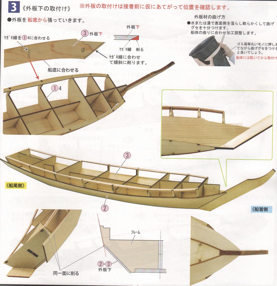
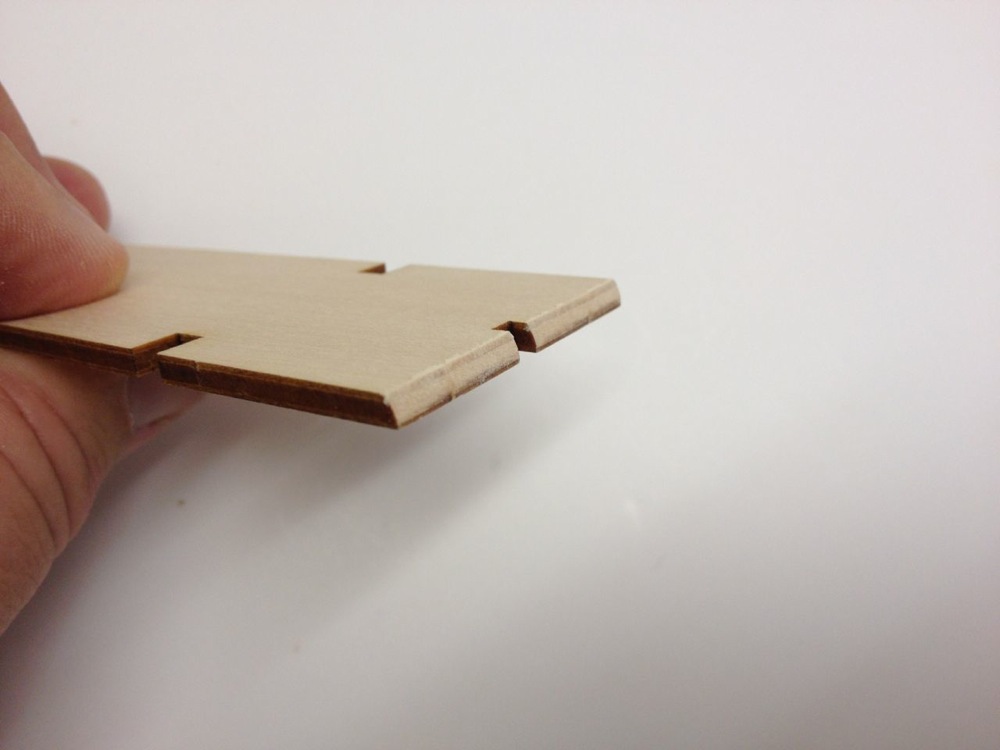
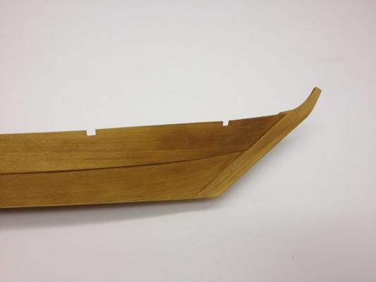
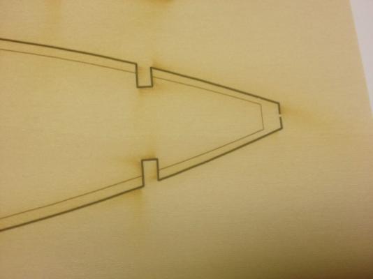
Hi Ken, Please do! It is a short build and it won't take long to see it to the end here. Woody Joe gave me the okay to use images from the instructions in my build log, so we're all on the up-and-up! As you can see, there's a lot of imagery will little text. What text you see is telling you things that are really pretty obvious if it wasn't there. Step 3 Attaching the Lower Planking • When fitting the planks, make sure the laser-etched alignment marks line up with frames before gluing the planks into place (The text in red) • Bevel the bow edge of the lower planks (laser cut parts 2 and 3) using the laser-etched lines as guides. • Bend planks by first soaking them in water. Bend the wet plank across a plastic bucket or similar curved surface for support. • When mounting the lower planks, make sure the laser-scribed marks line up with frame Probably the main issue here is bending the hinoki, which bends very nicely, but only when wet! Dry hinoki is very brittle, so don't go there without wetting the planks first. Not even a little bit, because I doubt you're going to be able to get replacement parts, and you're probably going to need to fabricate your own from basswood or boxwood maybe. Hinoki is very hard to find here in the States. It's not that it's a rare wood, it's just not something that you can get here. I managed to get a block of it from a Japanese tool shop in Berkeley, CA, but it's not big enough to cut any significant sized sheets from. It was just a piece of scrap they had laying around that they gave me. I've heard that Port Orford Cedar is very similar, but I've never tried it. Luckily, I've never needed to go that far. If I've lost a piece or used up the strip woods in a kit, there has always been enough scraps from the laser-cut sheets to come up with anything I've needed. The part of this build that I've been most concerned and careful about has been the position of these first hull planks. The inside edge of the planks at the bottom should line up with the bottom of the hull. You can see this in the bottom center diagram of the instructions. The last part of this step is sanding the top edge of the plank so that that the plank is flush with the upper part of the frames. This is necessary in order for the upper planks to lay flat against the frames and the bottom planks. Note the notch in the upper edge of the planks in the photo below. This notch allows the upper planks to seat nicely against the stem. Without the notch, I'm guessing the that fitting the planks into place would be much more difficult, require more bending, etc. I don't know for sure if this is a kit simplification, but Woody Joe seems to incorporate this on all their recently engineered traditional Japanese boat kits. Also, if you look at that forward frame, you'll note that there will be a gap between the frame and the lower edge of the upper plank. That appears to be how it is unless I've been doing something wrong with these builds. With the completion of this step, adding the two bottom planks, one might call them the garboards, the hull planking is half done! Clare

- 106 replies
-
- 11
-
-
- Japanese boat
- Wasen
- (and 2 more)
-
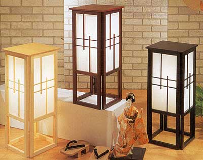
Building this model with an eye toward better understanding of the construction of traditional Japanese boats, I try to keep in mind that traditional boats are not constructed with a frame like this. Nor are they built on a mold. They're constructed in a loft and beams are used to push planks into position and to hold them while the work goes on. The real boats, often have only one or two frames, and these are added in after the hull is shaped. Most of the structural integrity of these boats comes from the edge nailing of the planks to each other and with the use of beams, which are mortised into the planks, locking them into place. A good source of information on this is boat builder Douglas Brooks and his website: Douglasbrooksboatbuilding.com. Those of us attending this year's NRG conference will have the rare opportunity to learn more about this man and his work as he's one of the scheduled speakers. The next phase of the build: Step 2: Finishing the Frame This is a very short step with only the following instructions: • Temporarily align outside plate (laser cut pieces 2, 3, 4 and 5) to aid in beveling frames. • File the edges of the three bulkheads closest to the bow and the three bulkheads closest to the stern so their edges are in line with the curve of the hull. By outside plate, we're talking about the planks, which are very long and wide on these boats. So, basically, bevel the frames. The instruction suggest this is only necessary for the first three and the last three frames. Nothing to really illustrate here, but I found a Woody Joe ad for the kit to maintain visual interest here! Yes, it's got lights! Clare
- 106 replies
-
- 7
-
-
- Japanese boat
- Wasen
- (and 2 more)
-
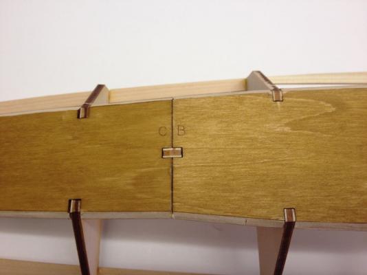
Hi Si, Actually, it's your getting the Hacchoro kit that gave me incentive to get this build going. I figured it would help me write up my Hacchoro notes since the two kits are so similar in terms of hull construction. And I hope you don't mind me pointing out how MSW can connect you up with ship modelers that are a lot closer than one may think. All, Si, who I met here on MSW, turns out to live only about 8 minutes drive from my house by freeway. But, even more amazing is that he works just a few blocks away from my house! It's a Small Model Ship World after all... Now, regarding the Yakatabune kit, the next step is to add the stem. This is a bit tricky as it needs to glued to the bow end of the trame, needs to sit perfectly vertically when viewed from the front, perfectly centered on the frame, and lined up straight with the keel frame. Before doing any of this, I decided to go ahead and add a little bit of taper to the stem. The plans don't call for it, but I think it looks good to add some taper. The top end, however, needs to have it's full size in order for an end cap piece to fit correctly later in the build. So, I gave the stem a gradual taper with no taper at the top, most taper at the deck level and less taper down at the base of the stem. This photo of a modern built traditional yakatabune shows stem taper. Once tapered, I went ahead and started using Transtint wood dye to color the parts. I made a mixture some time back – a 2-bottle batch of Dark Maple and Honey Amber. It only takes a small amount of dye mixed in with denatured alcohol. In the past, I made a much lighter mixture, but decided to go a little bit darker this time. I applied this to the stem, the bottom boards of the hull and also the hull planks, still on their laser-cut sheets. So, the rest of Step 1 text reads: • Attach bottom plate to keel frames. Note: Until glue dries, keep assembly weighted down on a flat surface. - Bevel top of frame 8 flush with keel frame. - File the joint between the bottom plates so there is no gap between them. - File top of bottom plate so that there is no gap at the stem. - Please glue stem firmly to frame. • Attach deck supports 7 A through D and 8 E and F. The bottom boards, now died, were glued into place. Note that the part identifying labels are clearly visible on the bottom of the model. Since this is on the very bottom of flat hull, these won't be at all visible. They are etched on the outside of the pieces because the laser cutter only burns from one side of the sheet and etched lines for the beveling has to be on the outside of the hull, so the identifying letters have to be on the outside too. Bottom boards in place. Below, you can see the deck supports glued into place. Unfortunately, I didn't have an overall picture of the hull at this point, just close-ups. Deck supports in place. Thus ends Step 1 of the instructions. On to Step 2... Clare

- 106 replies
-
- 12
-
-
- Japanese boat
- Wasen
- (and 2 more)
-
Hi Chris, Roger and I have talked about it, and he has reached out to them. Initially, they didn't seem too interested, but I've also been in touch with Woody Joe about it. I'm somewhat protective of Woody Joe. As people probably noticed by now, I really like the company and their products, and I'd like to see them do really well. Ages of Sail could potentially carry the kits to make them easier to get here, but I'm not sure how these would be marketed. Also, since I do some work for Ages of Sail, I fear getting caught in the middle of any possible issues. Not there would be any issues, but I'd feel responsible, and wouldn't want to have to take sides on something, so I'm kind of hesitant to push the two together. Plus, I'd kind of hate to see the Japanese online sellers cut out of the picture. The main one I've been dealing with has been very helpful and even shipped an out of production kit to me that I ordered from Amazon Japan. I expect it needs to happen and will likely happen in the next year or so. Woody Joe is now trying to figure out what a good US outlet would be, and I can't really think of any unless they go with a distributor like Great Planes or Ages of Sail. Anyway, instructions need to be translated, and nobody has really talked about that yet. Clare
- 106 replies
-
- 5
-
-
- Japanese boat
- Wasen
- (and 2 more)
-
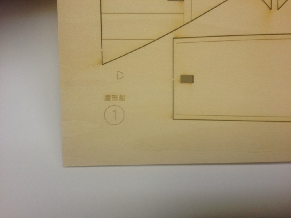
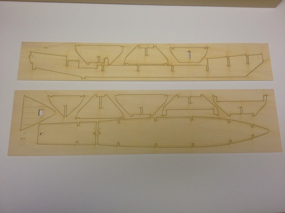
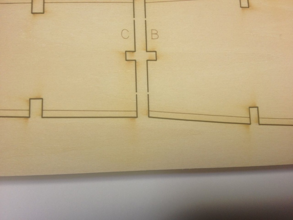
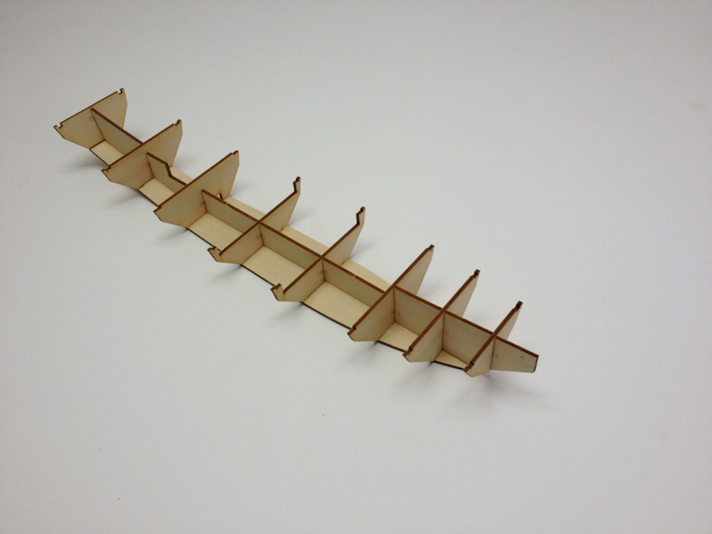
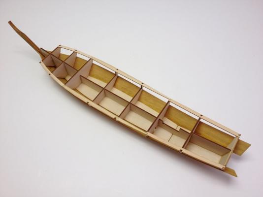
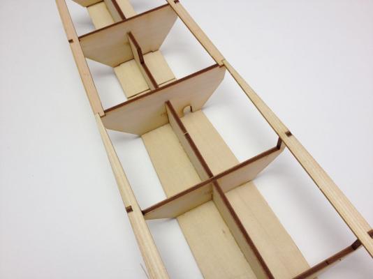
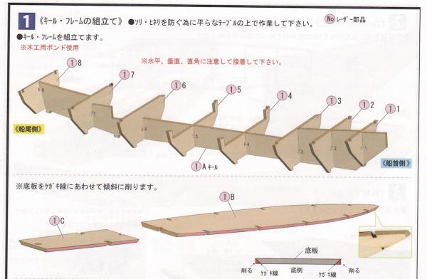
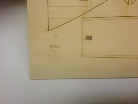
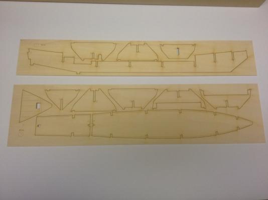
I though I should mention something about the name. Yakatabune is pronounced Yah-kah-tah-boo-ney. Pronouncing Japanese is actually pretty easy. Each vowel is only pronounced one way. It's not like English. Also, there is no accent of syllables. All words are pronounced flatly. We here in the US would tend to say yah-KAH-ta-BOO-ney, but it's not like that. There is no emphasis on any syllable. On to construction... This kit is not built in a traditional Japanese fashion, though it represents a traditional boat. Woody Joe in redesigning the kit, gave it a western flair, simplifying the construction a bit for us by adding a standard internal framework. The use of relatively thin wood for structural parts means that there is less charring of the wood. Parts are very easy to find. In the image below, the parts are identified by the number 1 in a circle with a light red (pink) background. The pink color indicates that the part is a laser-cut part and the number indicates the sheet number where the part is located. The letter next to this identifies the specific part. Below you can see the sheet number, a "1", and one of the part numbers, "D" The frame sheets are the largest laser cut sheets in the whole kit. Most laser cut sheets are relatively small at maybe 8" to 10" long and about 1-1/2" wide. The frame sheets are some kind of high quality plywood, possibly birch, but all other wood in the kit is Japanese Cypress, a very aromatic wood called Hinoki (He-No-Key), which is a pleasure to work with. In fact, every time I sand the wood, I have to stop and smell it's soothing aroma. Very theraputic! 1 - Keel, Frame Assembly – That's translated directly from the instructions with the help of a scanner, online free OCR, and Google and Bing Translation. The other text in the instructions say: • Assemble the keel and frame • Use wood glue • Please work on a flat table to prevent twisting of frame • Use care to maintain horizontal and vertical angles • Bevel the bottom plate according to the laser scribed lines Plus there are some labels indicated bow and stern ends and labeling part 1A the "keel". Also there are inset images showing the beveling of the bottom plates. All in all, there is nothing here that an experienced ship modeler couldn't figure out from just the drawings, common sense, and some model building experience. The laser cutting of the parts is done to close tolerances and the frames fit very nicely. As you can see from the photo below, it should be pretty easy to get the right frames in the right locations. The bottom plate, or floor of the boat, has to be beveled to match the angle of the frames. But, this is simplified by the presence of laser scribed lines, which indicate the extent of the beveling, so beveling is something of a no-brainer. There are actually two floor piece that fit together and the edges between them do require a little beveling so that they fit flat. These are not laser etched because the etching would have to be on the back side of the piece. This last shot shows the frame and bottom boards put together. The above photo and the one below are actually from my Hacchoro kit build as I didn't have photos at this stage of the Yakatabune build. But, these particular parts appear to pretty much identical in both kits. Clare

- 106 replies
-
- 12
-
-
- Japanese boat
- Wasen
- (and 2 more)
-
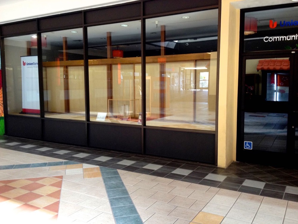
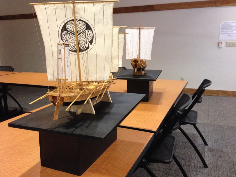
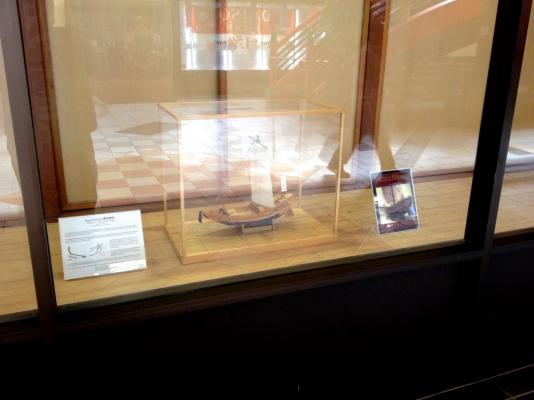
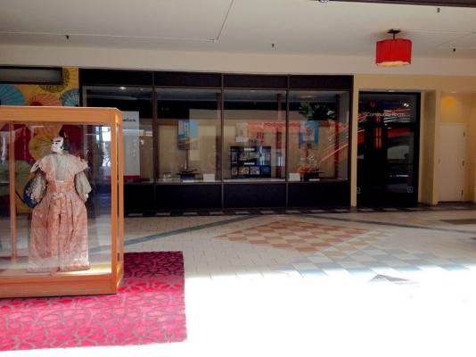
The reason I'm working on this kit now is that I've been developing a display of traditional Japanese watercraft based on Woody Joe kits (so far). My first display began with just the Higaki Kaisen, but it looked EXTREMELY lonely in a big display window, so I quickly added the Hacchoro. As a matter of fact, I kind of had to rush through completion of the Hacchoro kit, and the result was that I got the sails on upside down! I didn't notice it until it was pointed out to me. They are nearly square, but actually slightly larger at the top than on the bottom, with is opposite of what one would find on Western sailing craft. Embarrassing, but you live and learn! Initially, this was only a display of my Higaki Kaisen model. As you can see, it was pretty sad all by iself. Two's company. Better, but next display needs more to it. The display was set up in the window of the Community Room of Union Bank in the Japan Center Mall in San Francisco in Spring. The bank people were very pleased to have the display, so it was easy to arrange for version 2, or what I call Wasen Display 2.0. That is currently running from June 3 through July 10. Version 2.0 features new display pedestals I threw together to raise the models up and to create more contrast. I also took some decent photos and created some posters which I then hung from the back wall using plastic clips I had to make for the occasion. I learned I need to add more visuals for Wasen Display 2.0. Viewing this from a distance, people can see something to attract their attention. This is just a view of the models being prepped for the display. The Yakatabune will be part of Wasen Display 3.0. Probably that won't be much more than an augmented version of Display 2.0. No set dates for that yet, but I want to be prepared. Clare


- 106 replies
-
- 14
-
-
- Japanese boat
- Wasen
- (and 2 more)
-
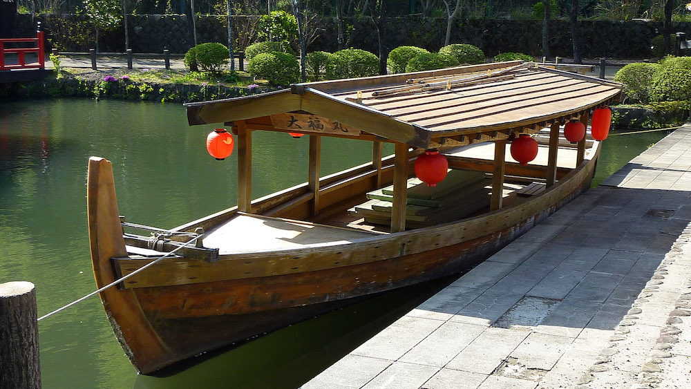
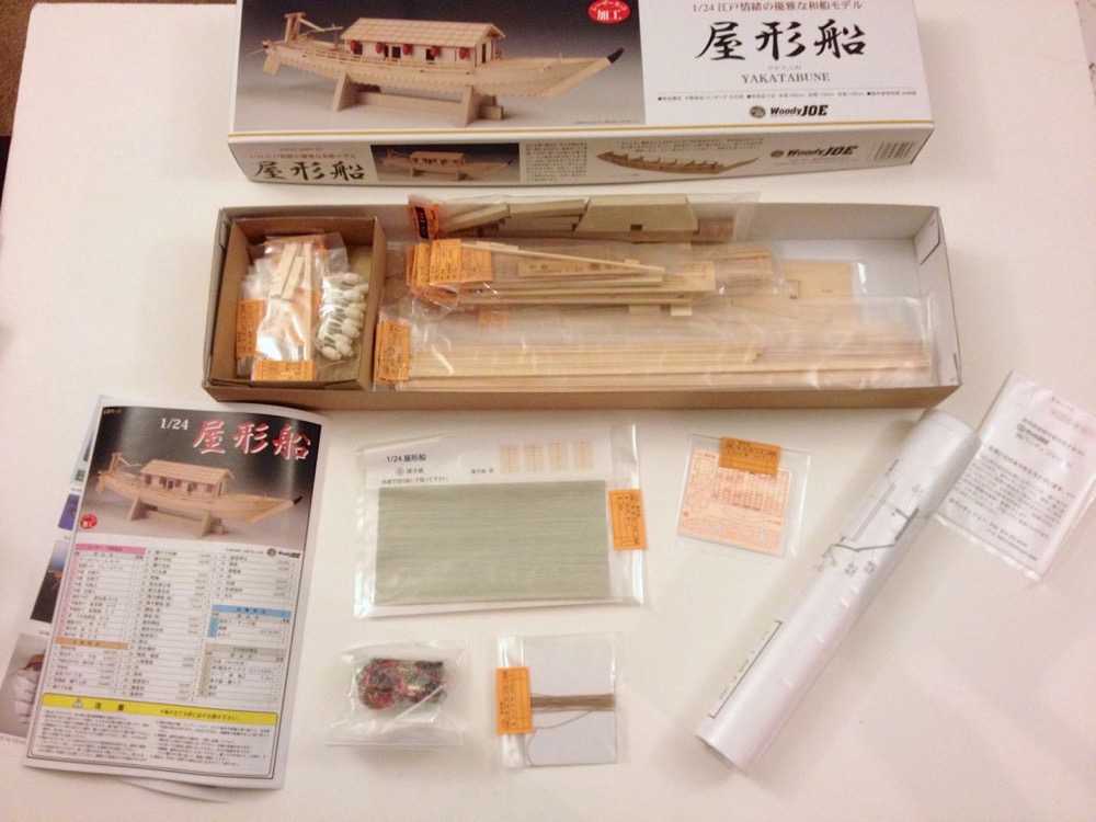
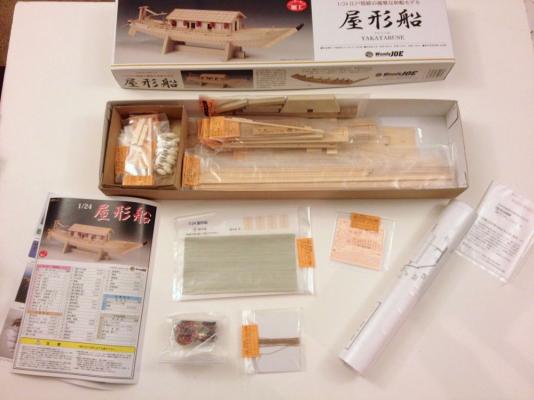
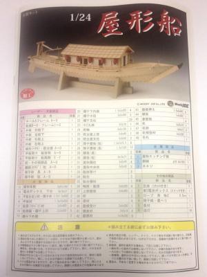
Someone out there is thinking "catopower is starting another build log? When's he going to finish the ones he's started?" Or maybe that's just me thinking it... Well, no matter, I need the model for my next display of Japanese traditional boats and I might as well write about it for others to enjoy. This is a pretty simple model and a quick build. Woody Joe calls it a 50 hour build. Its similarity to their fishing boat kit, the Hacchoro, leads me to think this sounds about right. The Yakatabune was a pleasure boat that became a popular way for commoners to enjoy leisure time during Japan's Edo Period, which began with the rise of the Shogun Tokugawa Ieyasu in 1603 and continued until the fall of the Shogunate in the 1860s, prompted by the arrival of Commodore Perry and the forced opening of Japan to the West. The Edo period was also the time of the closing of Japan to foreign contact and trade that ended with Perry's arrival. Under the single military ruler known as the Shogun, Japan had entered a period of relative peace and with it, economic growth. The period saw the rise of the merchant class and the fading influence of the Samurai. Prosperity brought with it leisure time. The Yakatabune was one way for commoners to enjoy a warm summer evening, floating along the river and maybe being entertained with drink and song. Today, Japanese people still seem to think of the Yakatabune as a symbol of the Japanese "Good Life". My mother, who is Japanese, talks about how people would float along Tokyo's Sumida river to watch fireworks at night. The boat may not seem as interesting to Westerners, but it seems to have a lot of meaning to many Japanese people I've talked to. The Kit The kit is from Woody Joe of Japan, which was revised last year about this time. It relies heavily on laser-cut parts and is built to 1:24-scale, making it about 25" long. Woody Joe kits aren't marketed in the U.S., so it usually has to be purchased on Ebay or Amazon. For the last year and a half, I've bought all my Woody Joe products from a Japanese online seller called Zootoyz. The store is a small one run by a gentleman by the name of Kazunori Morikawa and I like to send him business to help him out. His prices and service are good. The Yakatabune kit cost about $165 shipped by EMS, an Express service. As with all Woody Joe kits, the box is nicely illustrated, and the kit is well packed. No room for things to slosh around and get broken, and parts are all bagged and labeled. There is nothing loose in the box. The turn-off for a lot of people is that the instructions are written in Japanese. But, they are extremely well illustrated, and this kit appears to have no surprises the would be hidden in written warnings. I've found the same to be true of their 1:24-scale Hacchoro fishing boat, their Hobikisen mini-kit and their Utasebune mini-kit. Parts are easily identified by part numbers and these are relatively simple designs, and engineered so that just about anyone can build them. That's probably one of the biggest differences between Woody Joe and wester ship model manufacturers. Their models tend to be a little bit simplified in detail, so that any person who is interested in building one of their models, can be successful. Details on their kits can be on the light side. But, anyone who wants a more detailed build, can very easily add any level of detail desired. This will be my fifth Woody Joe kit, having built the HIgaki Kaisen, Hacchoro, Hobikisen mini-kit, and Iwakuni Castle. Details to follow... Clare

- 106 replies
-
- 14
-
-
- Japanese boat
- Wasen
- (and 2 more)
-
Hi Ed, Very neat! For those of us who enjoy solid hull construction, this is really isn't much different than a bread-and-butter or lift construction, is it? Just with the layers running a different direction and frames sandwiched in between. I'm really interested in following the build. Clare
- 191 replies
-
- 2
-
-
- young america
- clipper
- (and 1 more)
-
Fiebing's Leather Dye
catopower replied to JohnB40's topic in Painting, finishing and weathering products and techniques
Hi John, I've been using Fiebing's Leather Dye on a colonial schooner model and I've had pretty nice results with it on pear wood. I don't know how well it looks when used on other types of wood. But, on pear it's great. It has a wonderful sheen to it and it's as black as can be. I haven't tried to glue anything to the dyed wood and I'd be a little concerned about PVA adhesion. However, I've glued died wood into place. I'd generally score the died surface where the glue needs to hold and CA seems to work very well so far. Haven't had any joint failures at all. As others have said, it's best to dye parts before gluing them into place. I wouldn't even try to apply die on the model except for touch up. Then, I found that I could touch it up quite easily by using a small paint brush. Dyes don't penetrate wood as much as I would have expected. The surface layers of wood, if sanded off, will expose the natural wood. As I mentioned, you can touch it up pretty easily with a small brush. The nice thing is that because it's not paint, there's no build-up to worry about. Biggest issue I ran into was that if you do coat it with wood oil, be really carefully of applying it, because some of the dye will rub off onto your cloth and you can easy get some onto the surrounding wood. All that said, dye creates the nicest black finish if done right. Clare -
I am happy to announce that the Amati Revenge is no longer on the horizon. It's HERE! At Ages of Sail, the first kits shipped out to customers today. I had a chance to look at one of the kits and the first words that come to mind is: BIG! This is a really heavy kit in a large box. I would say that in terms of size of the kit packaging, it's on par more with Amati's Vanguard kit. This is an incredible looking kit... 19 sheets of plans. Instructions are in perfect bound softcover book format, 96 pages, full color. Lots of photos. Multiple sheets of photo-etched brass (they're in a sealed bag, so I didn't get a count, but it seems to me to be more than 7 sheets. No dummy cannons because it pretty much has a full-length gun deck. There's even a ladder up to a raised steering platform, and the whip staff is linked to the tiller. I was looking forward to seeing this kit's release, but it's not a subject that I was super interested in. I've completely changed my mind. This is such an Awesome looking kit – I want one! This is the danger of having such easy access to ship model kits... If you pre-ordered this kit at a discount, I have to say, I think it's a REALLY GOOD DEAL. Even at the full list price that Ages of Sail is listing it for, it's a GOOD DEAL. And I'm not just saying that because I'm doing some work for Ages of Sail. I'm not sure why this kit isn't priced higher than the Pegasus. I think someone screwed up and I suspect there's going to be some kind of a price adjustment in the future. Now, I can't speak to how well this kit goes together, so these comments are just about looking through the kit. Everyone who bought or is planning on buying this kit, all I can say is "congratulations" I'm extremely envious. Chris and Amati Model, you have outdone yourselves! Clare
-
Hi Jaxboat and all, the ship is on the horizon! I have it under good authority that the kits have arrived in the U.S. and are with the customs agent now, so they will be in the store in the next few days. They're just waiting on one pallet to arrive before delivering to the store, and the customs agent is just across the bay so shipment time from there is not significant. Won't be long now... Clare
-
The Amati Revenge is now online at Ages of Sail. The shipment of kits from Amati is officially in transit now and expected to arrive around the end of next week. In the meantime, Ages of Sail is accepting pre-orders at reduced pricing. Officially, it's pre-order pricing, but it should be good while the supply holds out. And there are a LOT of kits on their way. This is very exciting. I really don't need another project right now, but this looks SO good... There's an official posting by Ages of Sail on MSW here: http://modelshipworld.com/index.php/topic/8245-hello-from-ages-of-sail/?p=320105 Clare
-
Amati New Revenge kit- What scale will it be?
catopower replied to bear's topic in Wood ship model kits
This seems very odd. As of last week, Amati hadn't even announced what the price would be because not all the manufactured parts had been received yet. Clare -
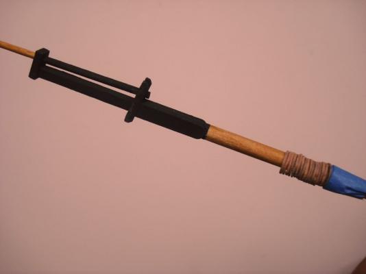
It's kind of funny writing a paper model build log. It's all about cutting some paper, gluing paper and painting parts. And then in the next step, cut paper, glue paper, paint parts. But then it gets difficult: cut paper more carefully, glue paper very carefully, and with a very steady hand, paint parts. Okay, there's more to it than that, but not much to report except basic progress. I assembled and added what Anatomy of the Ship calls the jeer bits. I couldn't quite gather what the instruction sheet was trying to indicate regarding the windlass handles. The kit includes tiny paper pieces that I would never be able to make use of, so I just used some 26 gauge black annealed steel wire. I also assembled the bowsprit bitts. Somehow the space between the bitts came out the right size to fit the heel of the bowsprit. That, I made from birch dowel. I wanted a square-stock piece, but all I had were dowels. Since the bowsprit was to be 3/16" diameter, I had to work backwards and do a bit of math in order to determine the width of dowel I'd need to start with since the diameter had to equal the widest cross-section of the square heel of the bowsprit. Here's another view of the bowsprit bitts and main windlass. Both are actually only temporarily in place, not glued. For all the bitts, I've embedded straight pins into them for strength. Here's a view of the mast with mast hoops. I used a small piece of blue painter's tape to keep from losing the hoops.


- 121 replies
-
- 13
-