Glenn-UK
-
Posts
3,170 -
Joined
-
Last visited
5 Followers


Recent Profile Visitors
7,911 profile views


-
 Nick 843 reacted to a post in a topic:
Duchess of Kingston 1798 by Glenn-UK - Vanguard Models - 1:64 - Commission Build
Nick 843 reacted to a post in a topic:
Duchess of Kingston 1798 by Glenn-UK - Vanguard Models - 1:64 - Commission Build
-
Craigie65 reacted to a post in a topic:
Duchess of Kingston 1798 by Glenn-UK - Vanguard Models - 1:64 - Commission Build
-
BLACK VIKING reacted to a post in a topic:
Duchess of Kingston 1798 by Glenn-UK - Vanguard Models - 1:64 - Commission Build
-
Ryland Craze reacted to a post in a topic:
Duchess of Kingston 1798 by Glenn-UK - Vanguard Models - 1:64 - Commission Build
-
palmerit reacted to a post in a topic:
Duchess of Kingston 1798 by Glenn-UK - Vanguard Models - 1:64 - Commission Build
-
Knocklouder reacted to a post in a topic:
Duchess of Kingston 1798 by Glenn-UK - Vanguard Models - 1:64 - Commission Build
-
ccoyle reacted to a post in a topic:
Duchess of Kingston 1798 by Glenn-UK - Vanguard Models - 1:64 - Commission Build
-
ccoyle reacted to a post in a topic:
Duchess of Kingston 1798 by Glenn-UK - Vanguard Models - 1:64 - Commission Build
-
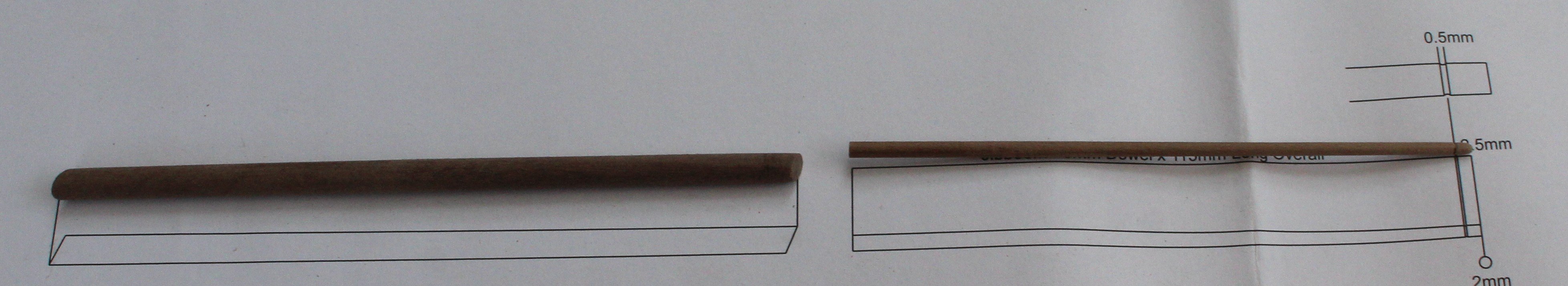
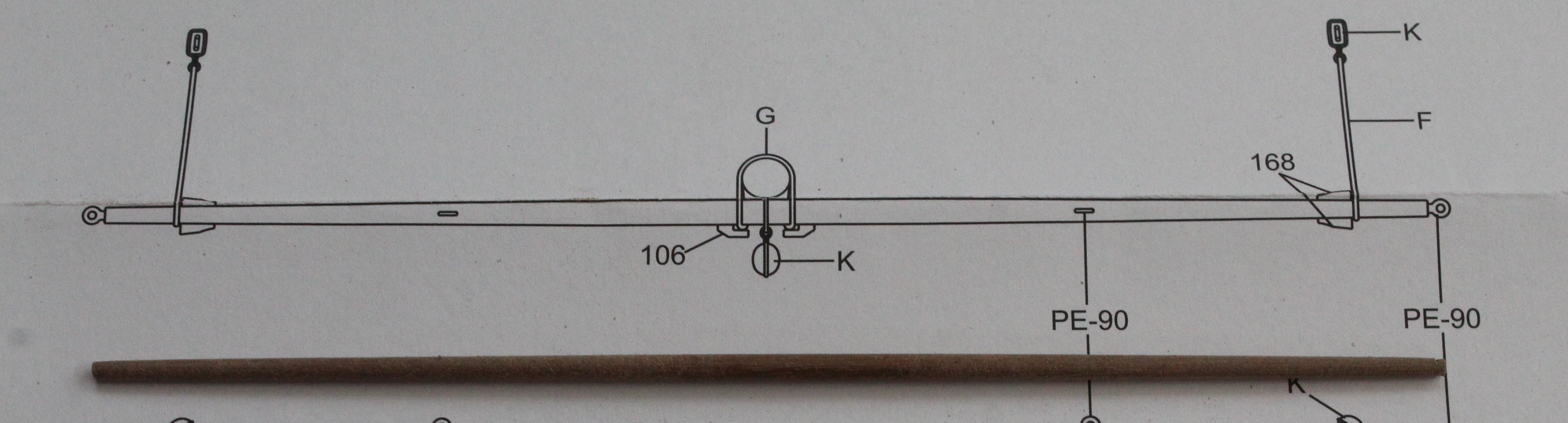
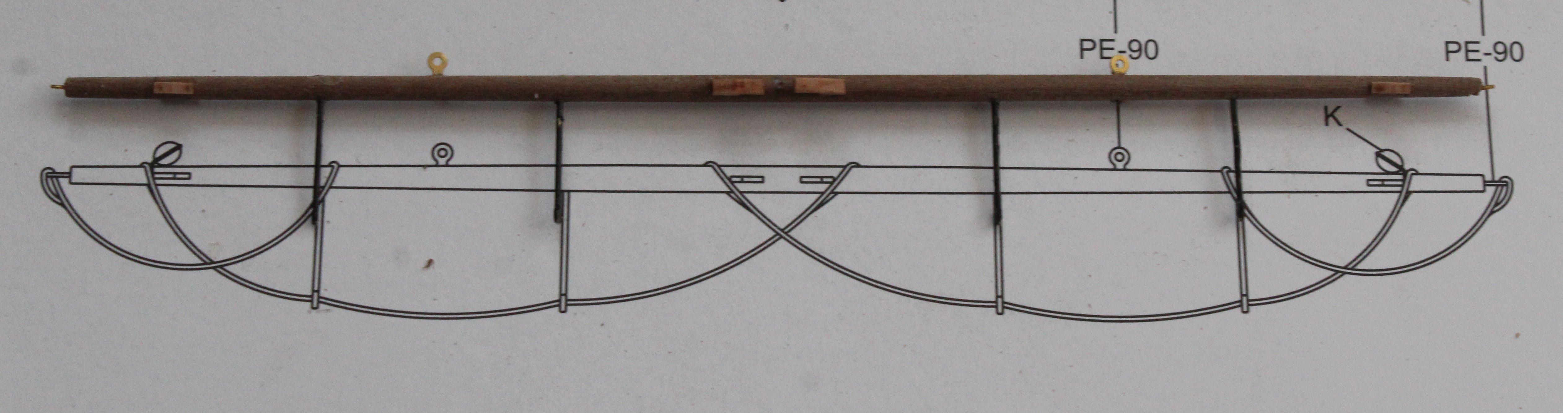
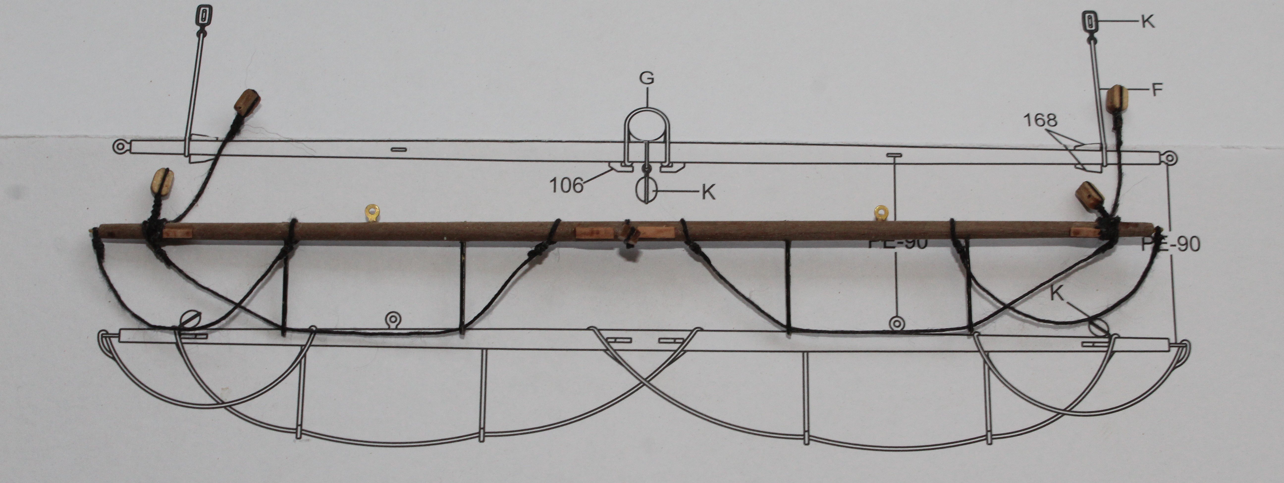
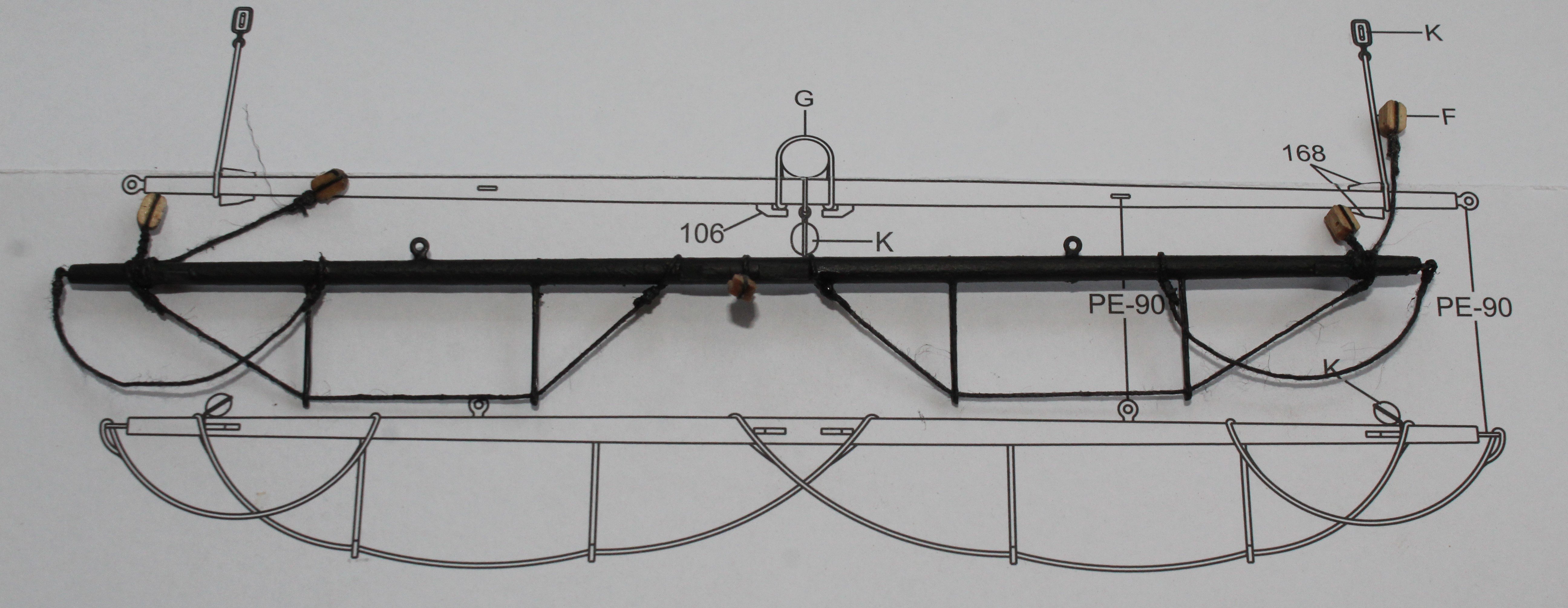
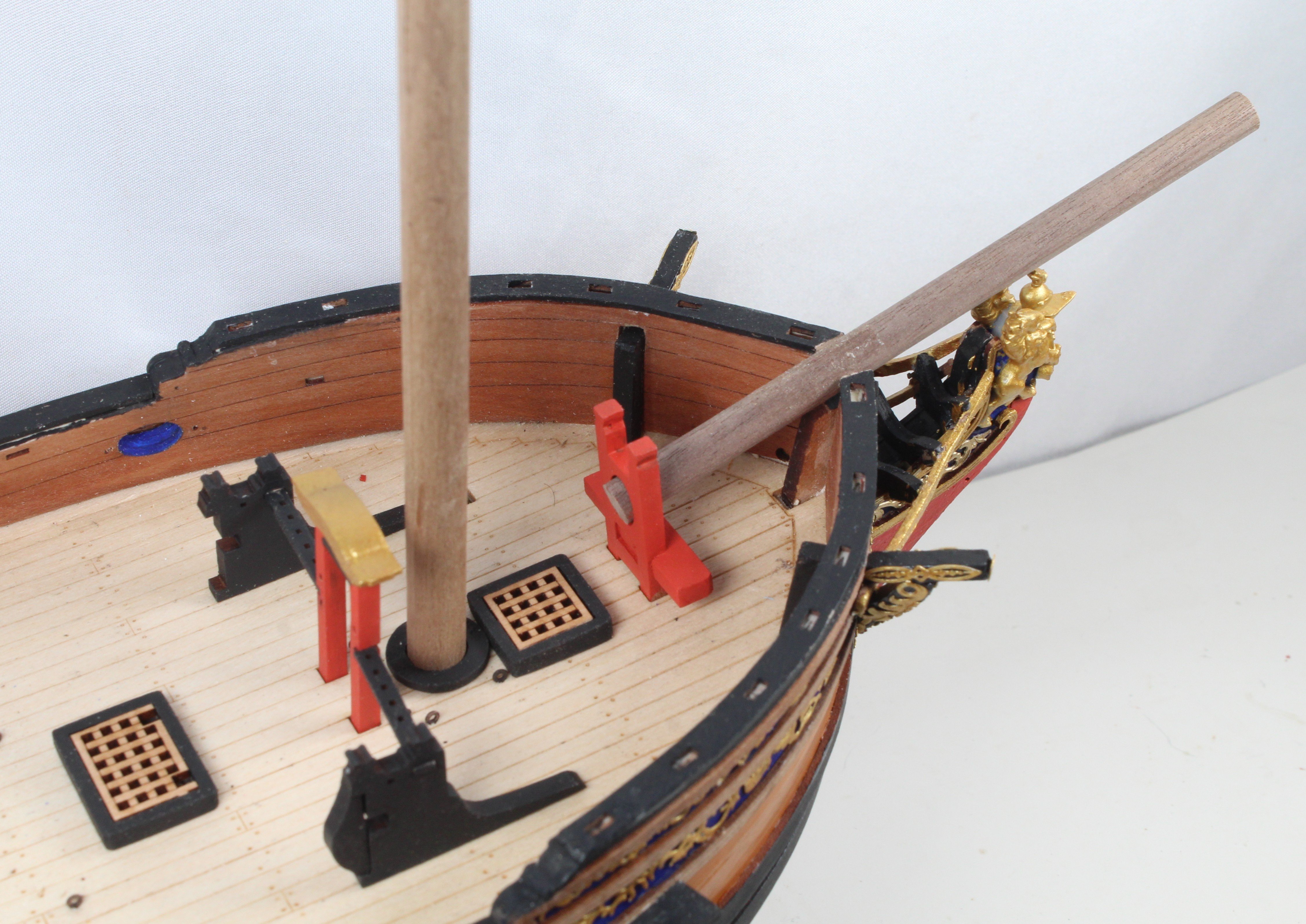
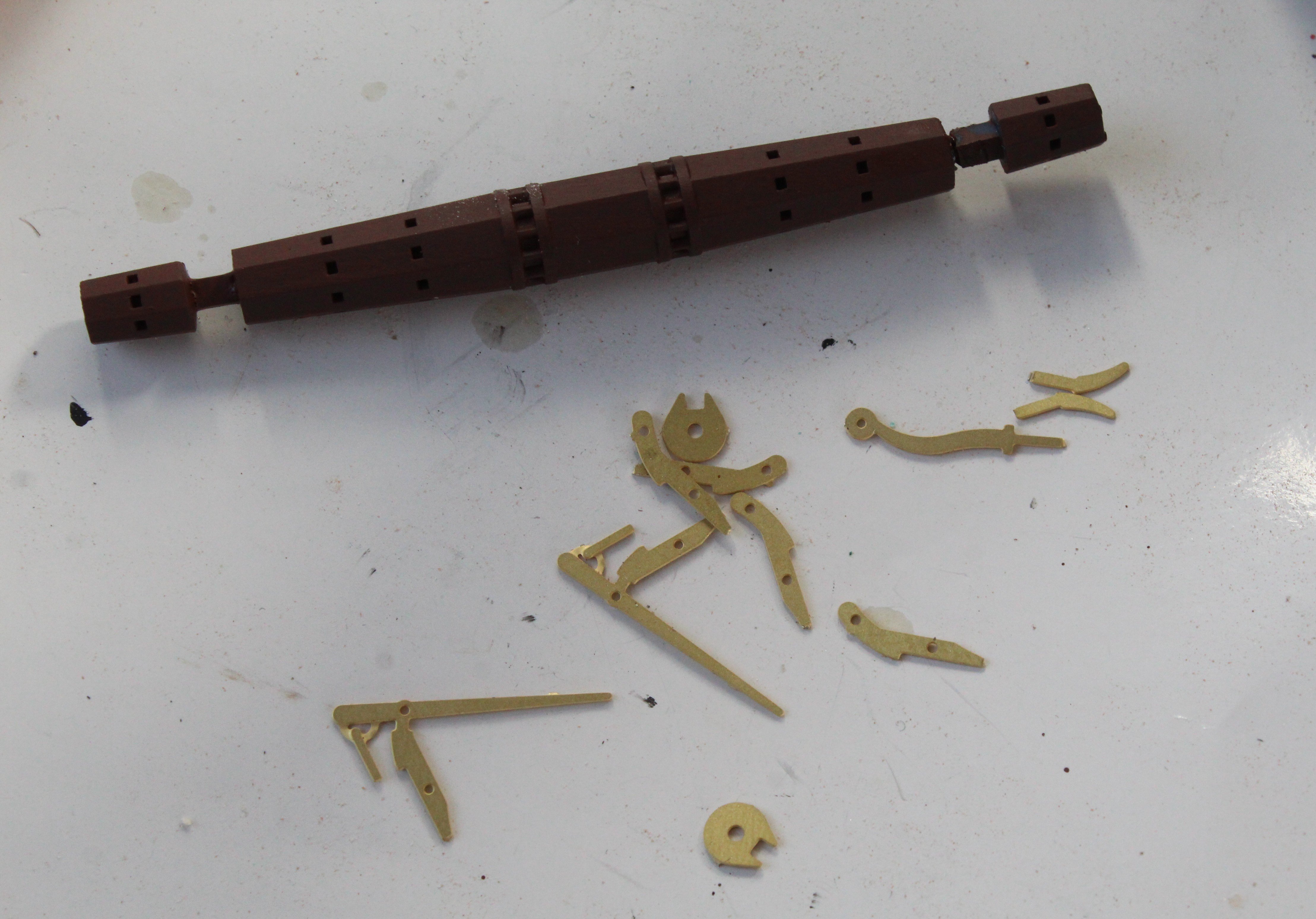
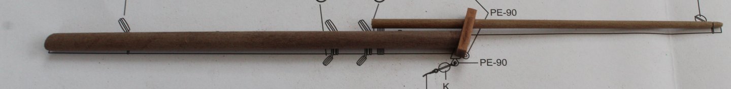
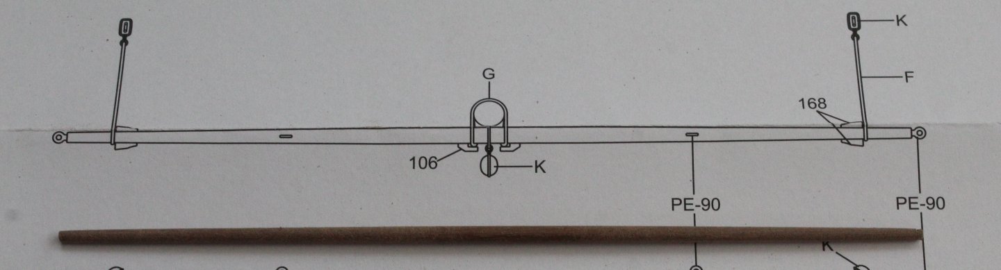
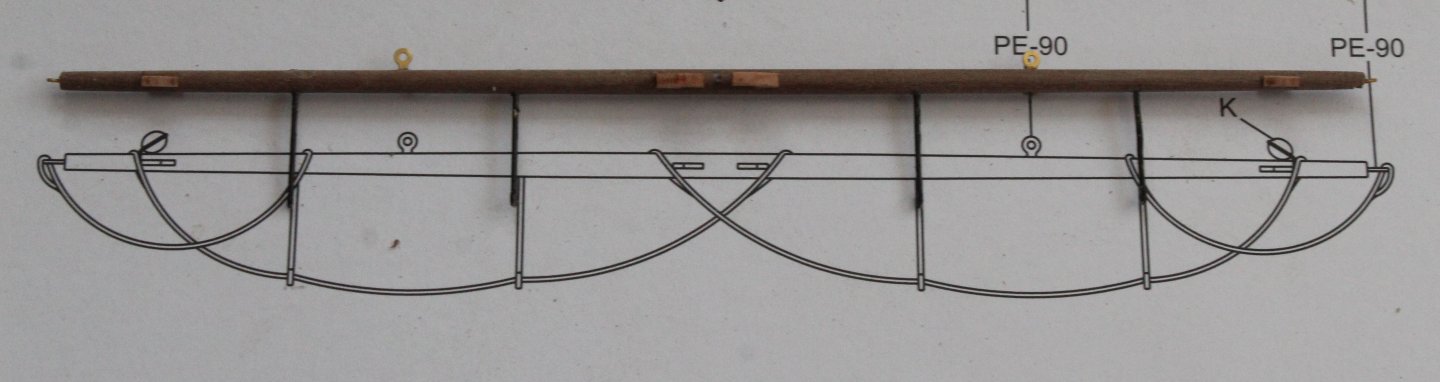
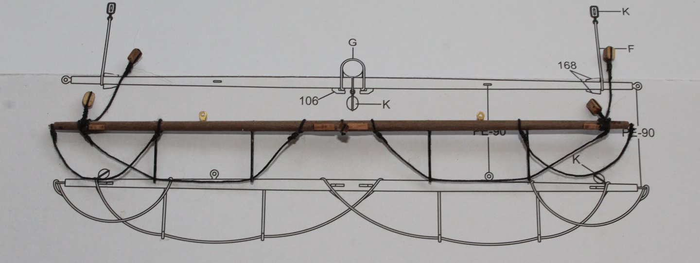
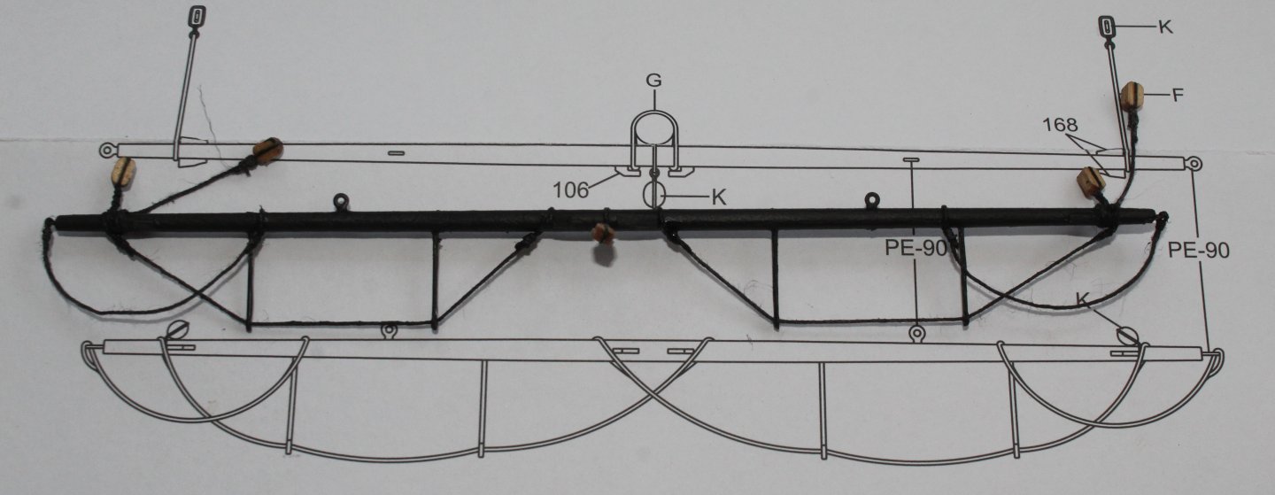
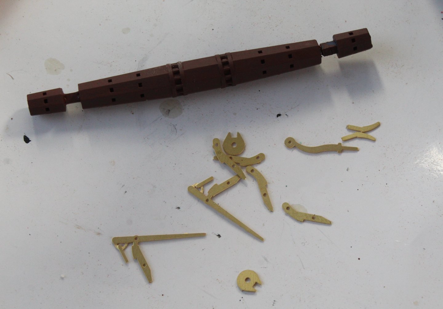
 Build Log – Post 41 (22/01/26) Task 64 – Start of mast and Yard Production I have cut all the dowels for the various yards and masts so there are ready to be shaped and have the various blocks and PE parts added. I decided I would start with the bowsprit, jibboom and spritsail yard. In the first picture the bowsprit and jibboom have been cut to length and tapered. In the next photo the I am test fitting the bowsprit and jibboom with the bowsprit cap. All looks good. In the next photo I have tapered the spritsail yard. In the next photo I have added the PE parts and cleats. In the next photo I have added the various blocks and footropes. The more eagle eyed reader will note that I have made an error with the footrope rigging. I will correct this mistake. Finally, the spritsail yard has been painted black.
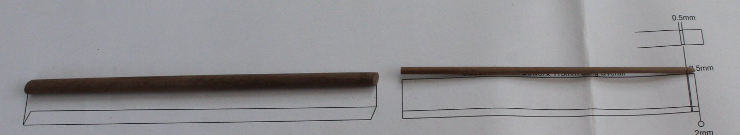
-
Glenn-UK reacted to a post in a topic:
HMS Indefatigable 1794 by Mowzer - Vanguard Models - 1:64
-
RossR reacted to a post in a topic:
Duchess of Kingston 1798 by Glenn-UK - Vanguard Models - 1:64 - Commission Build
-
brunnels reacted to a post in a topic:
Duchess of Kingston 1798 by Glenn-UK - Vanguard Models - 1:64 - Commission Build
-
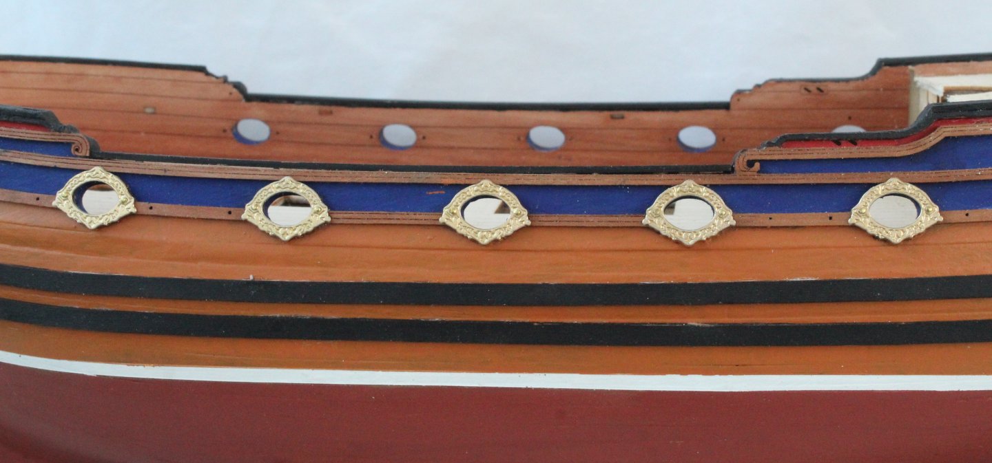
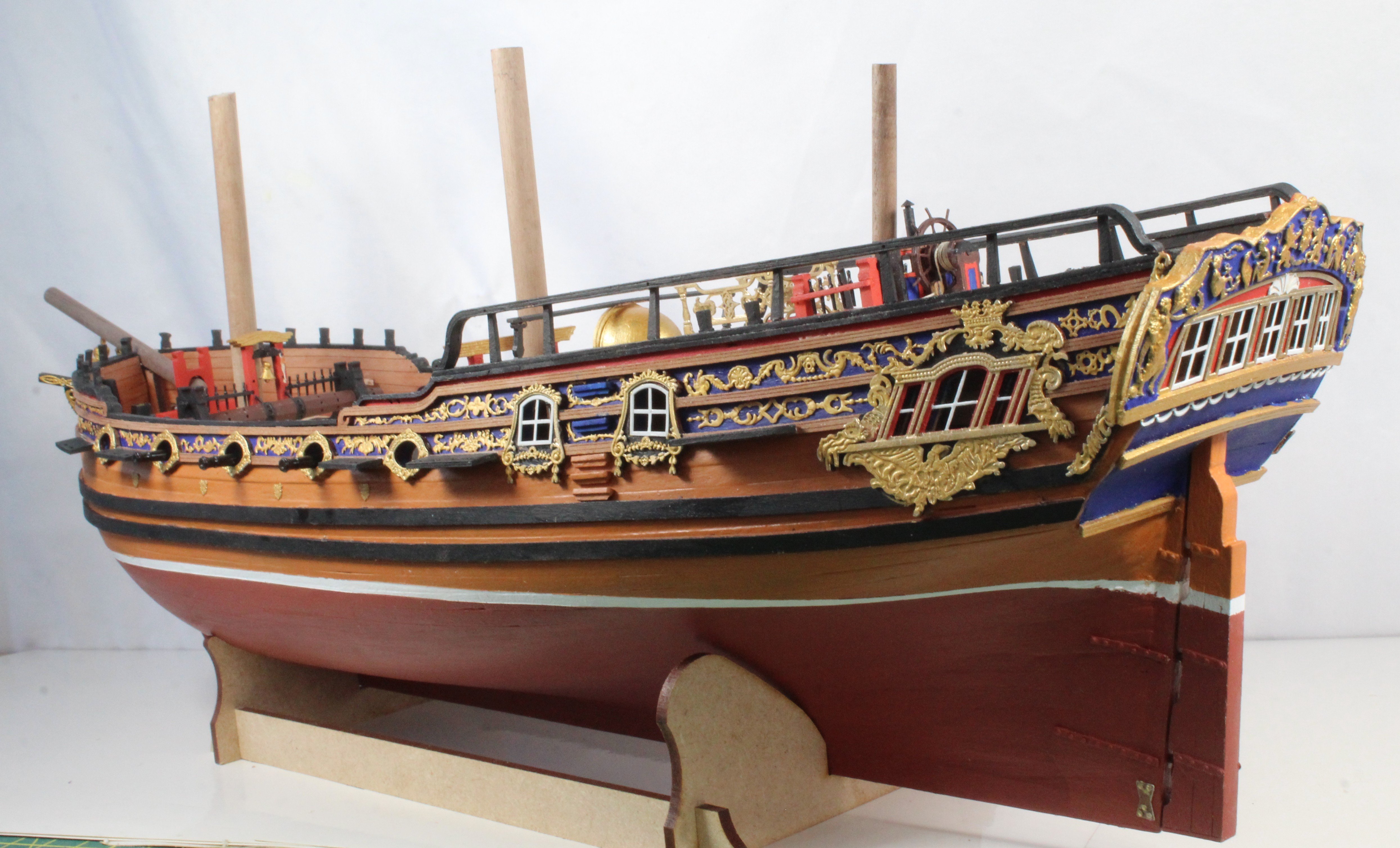
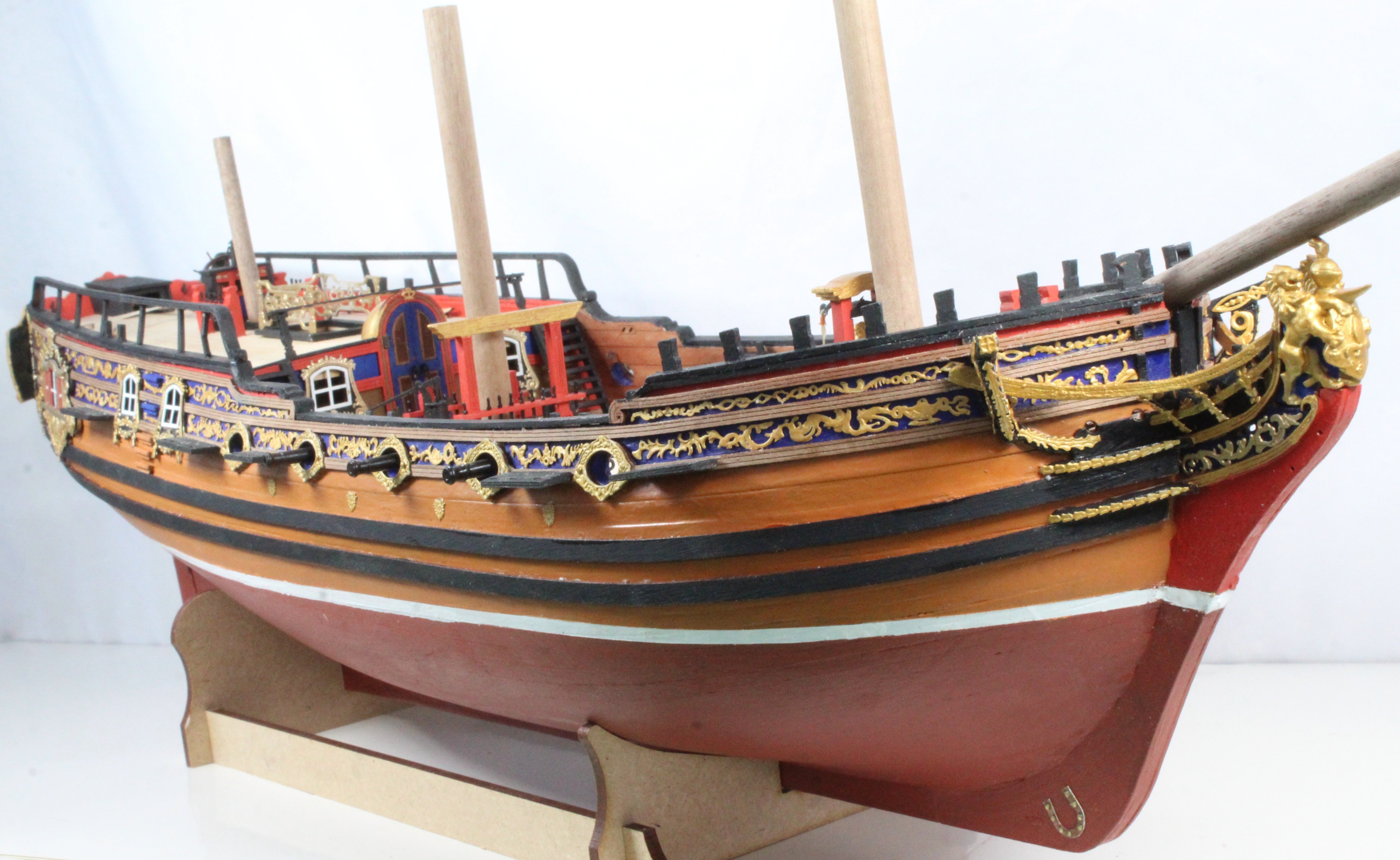
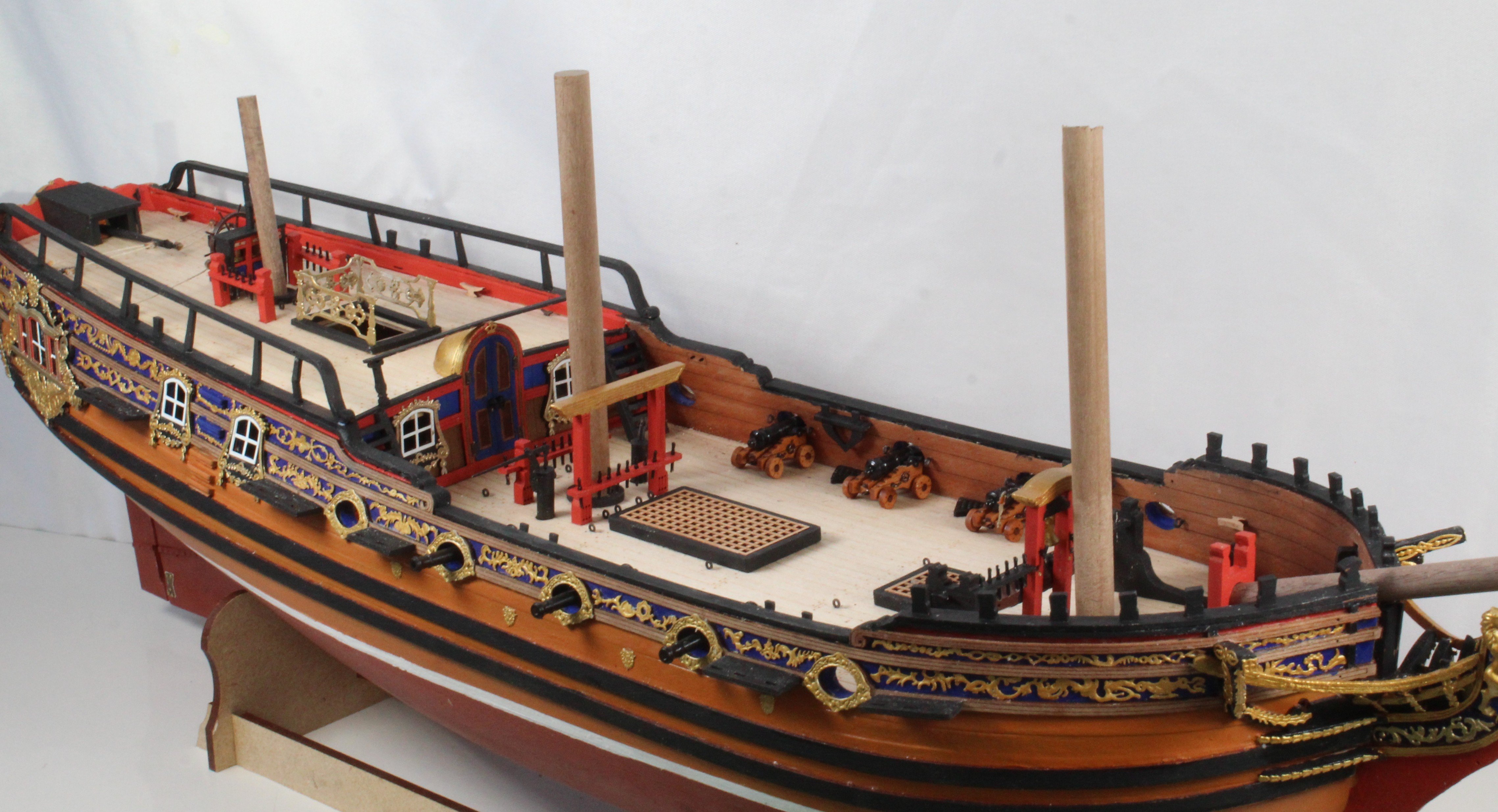
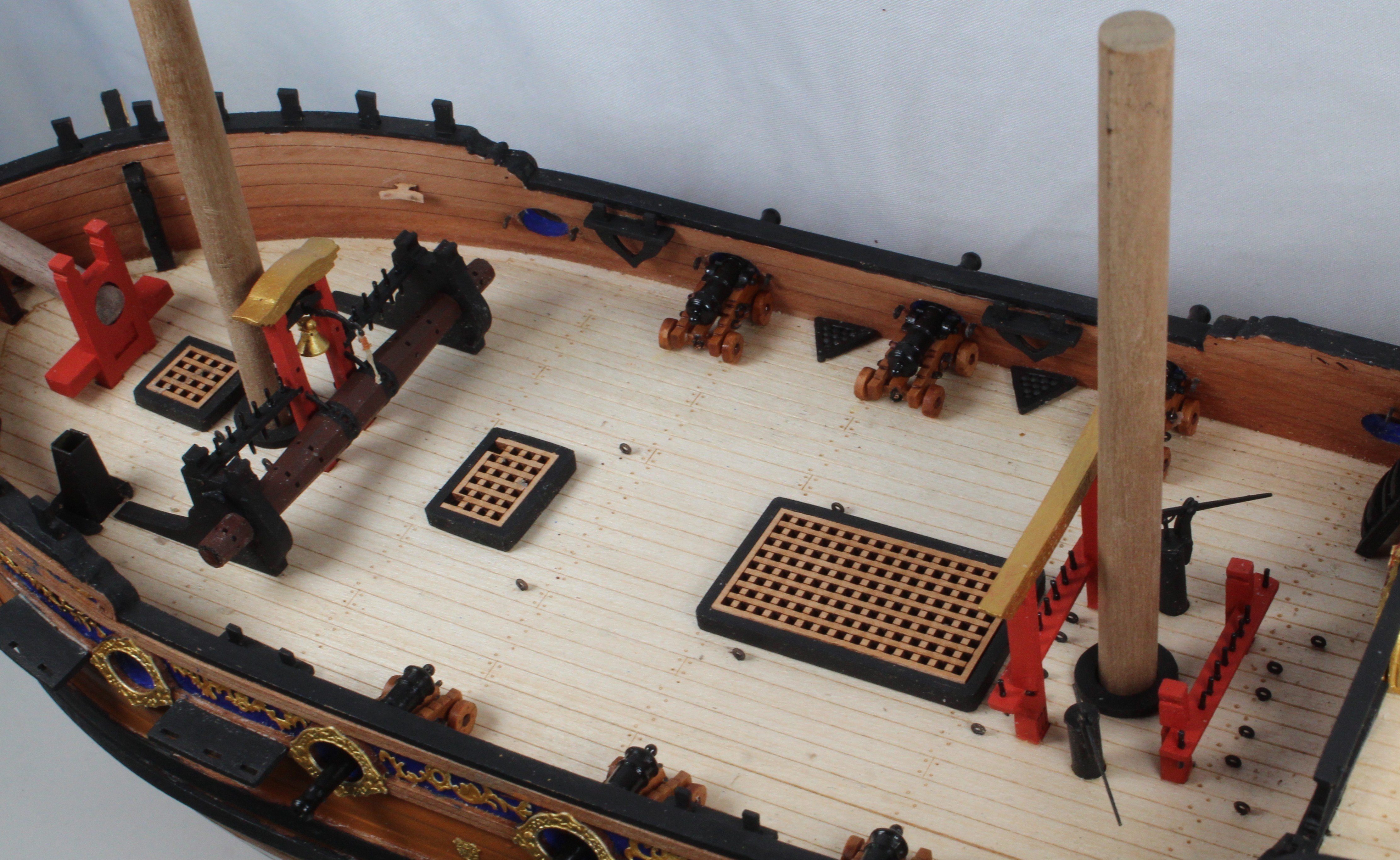
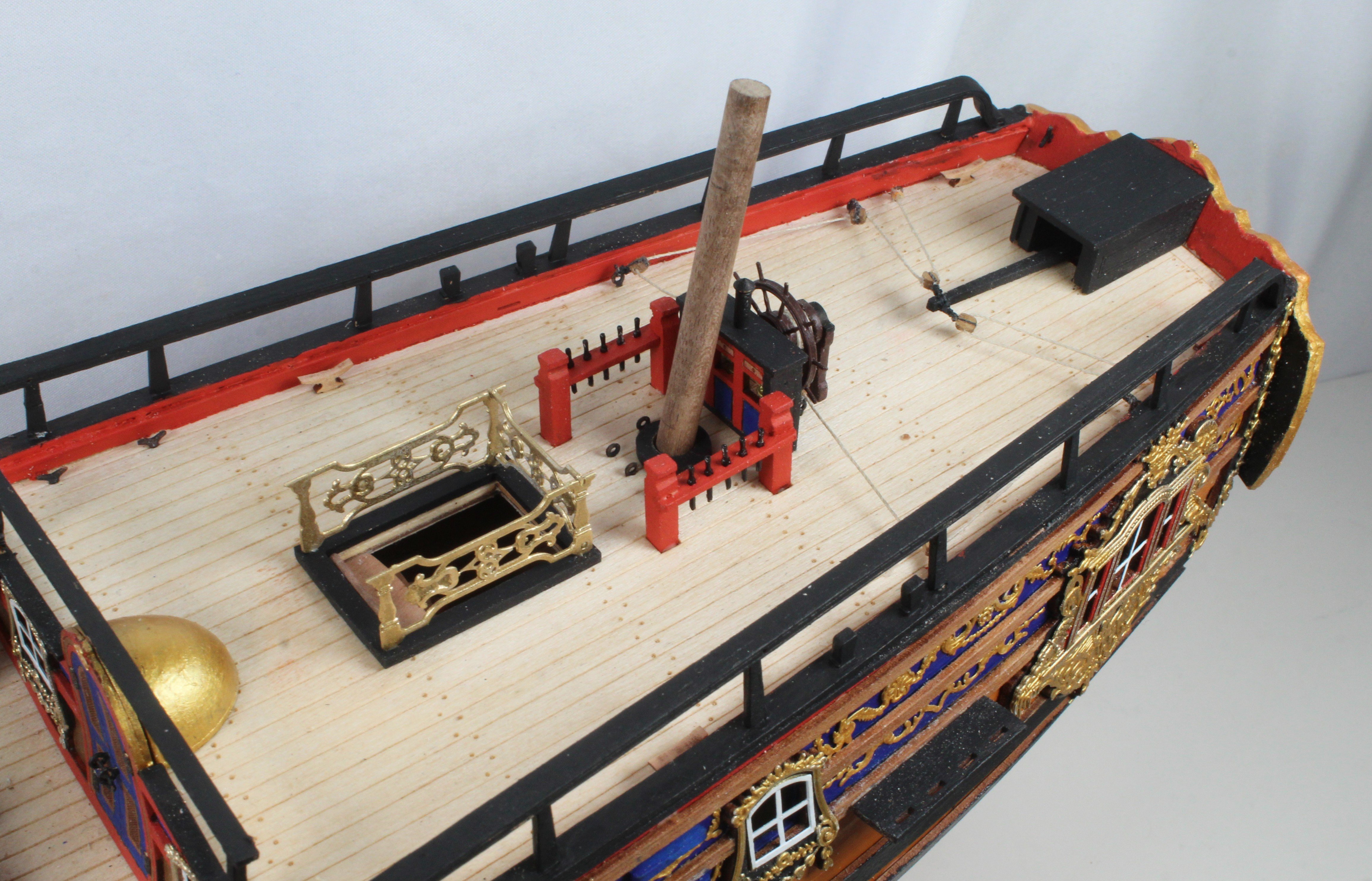
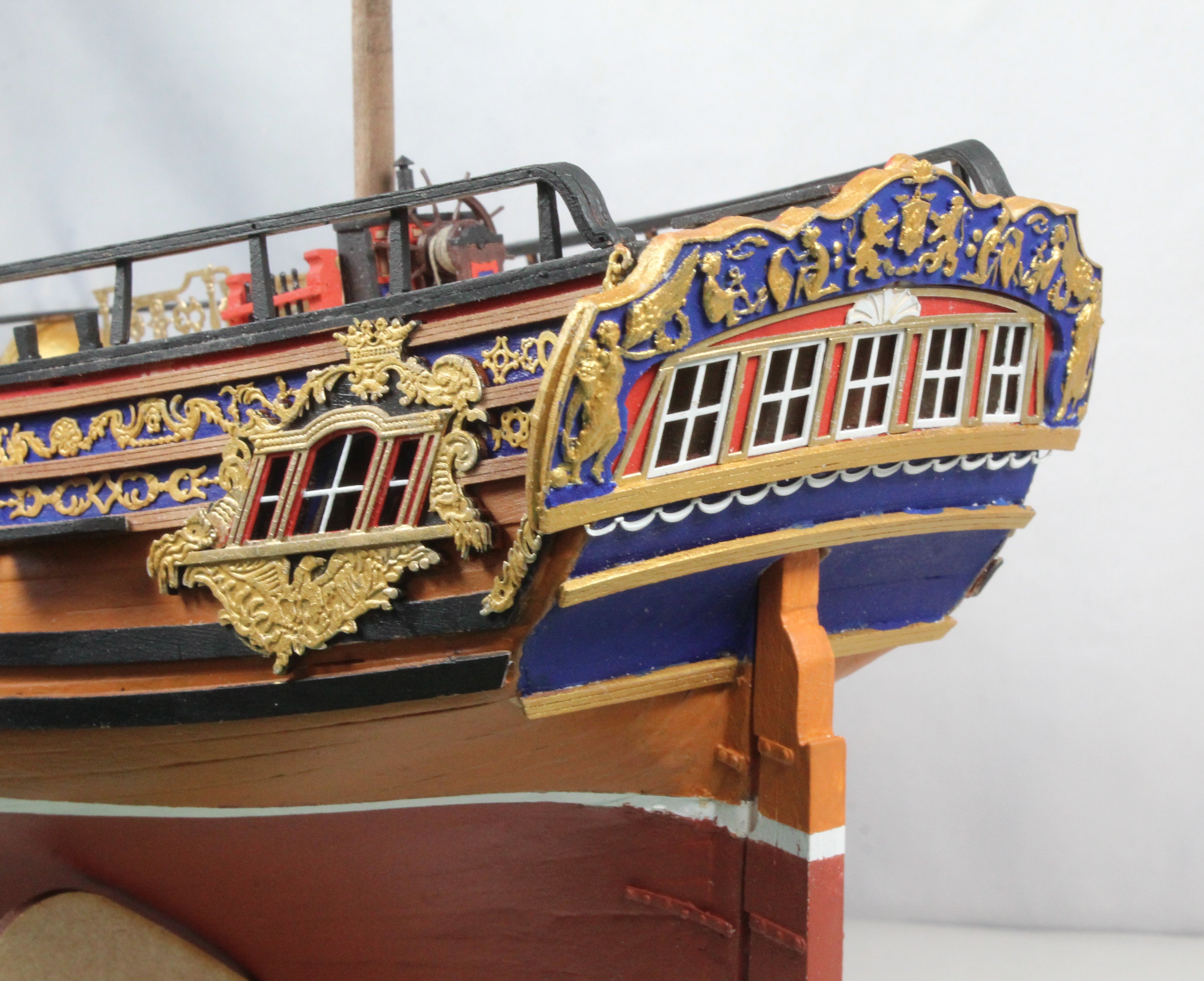
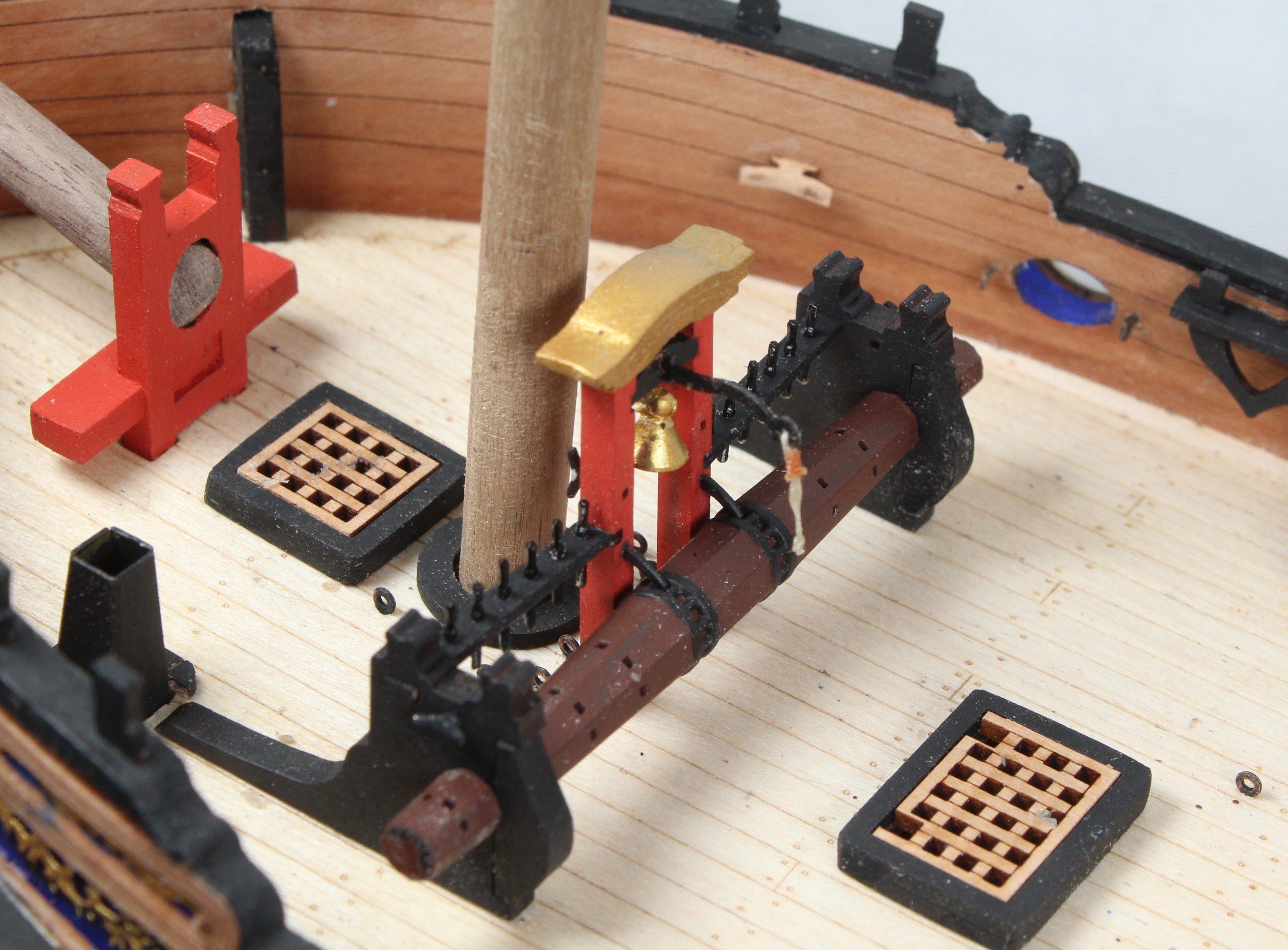
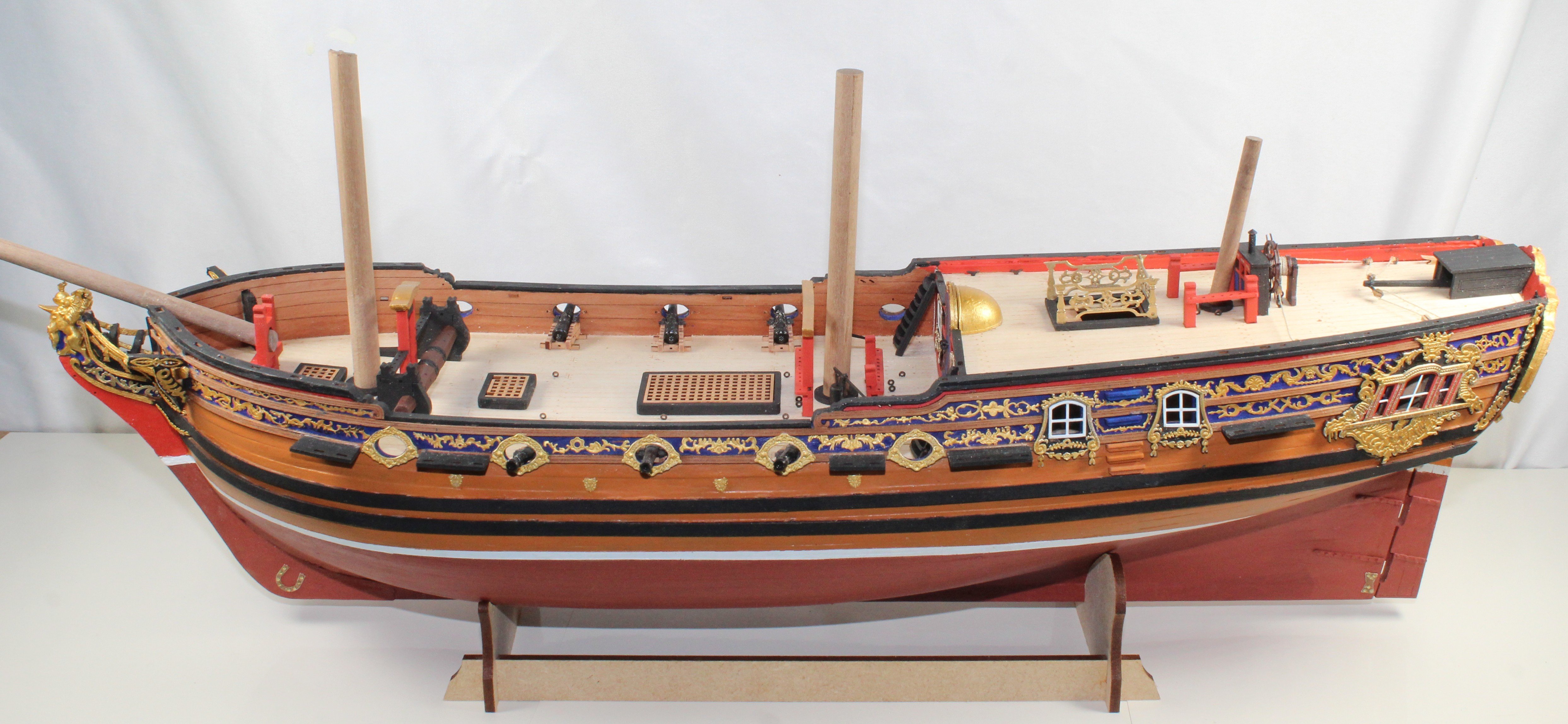
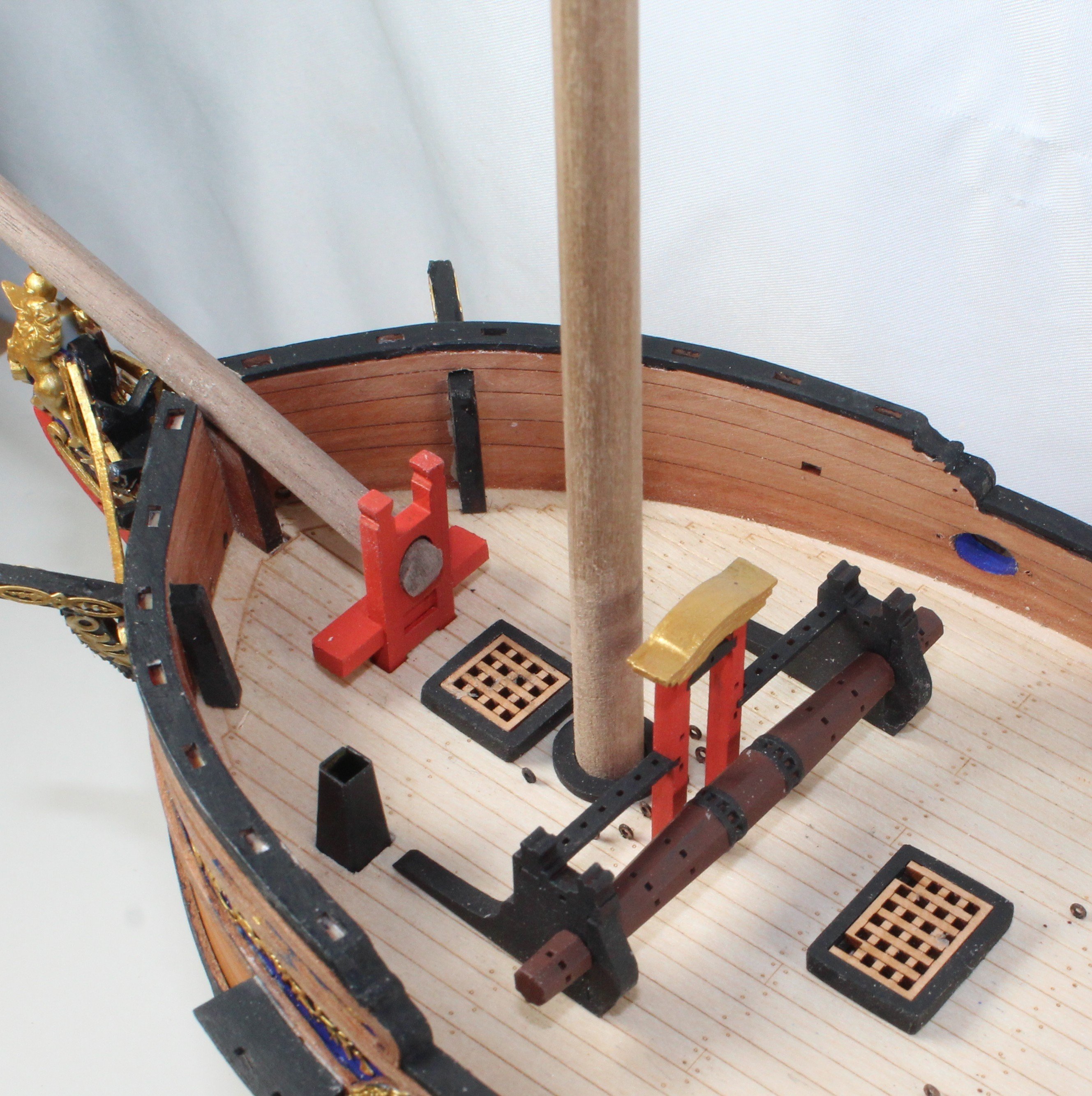
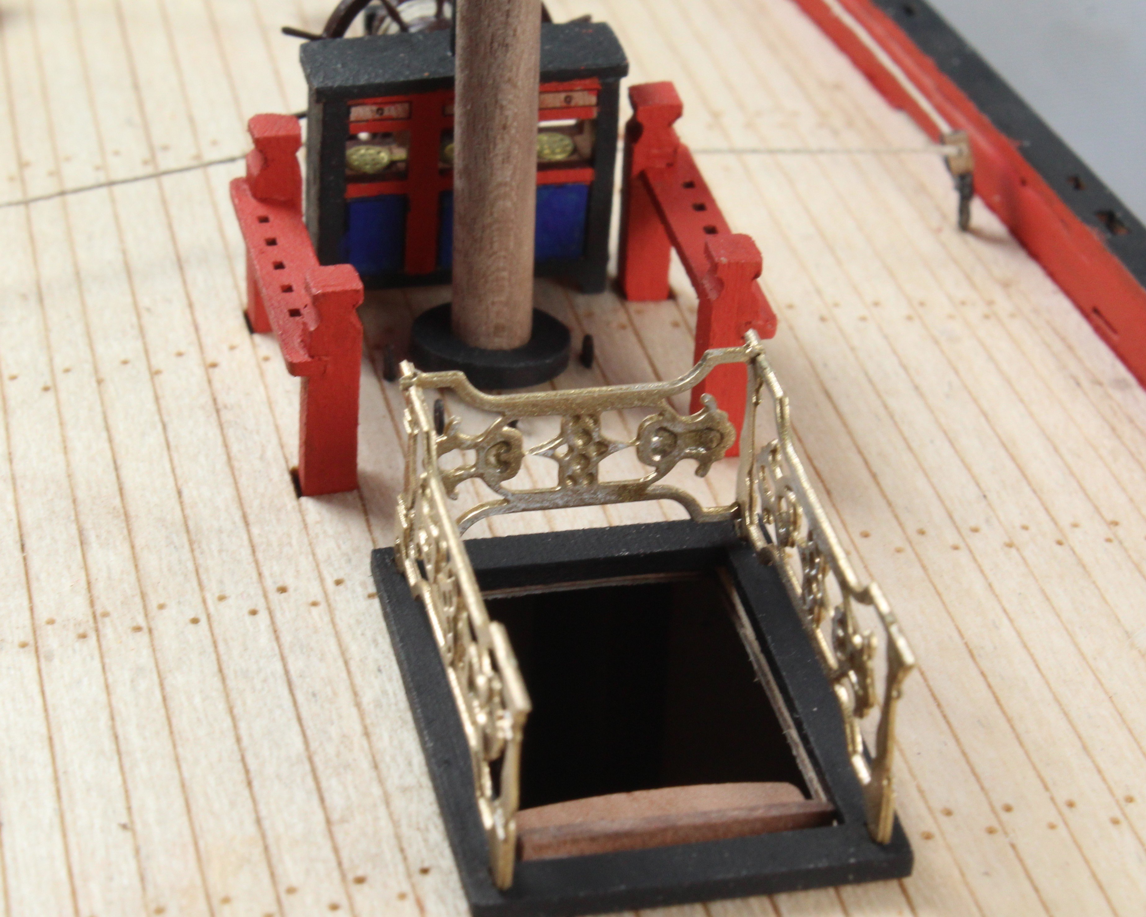
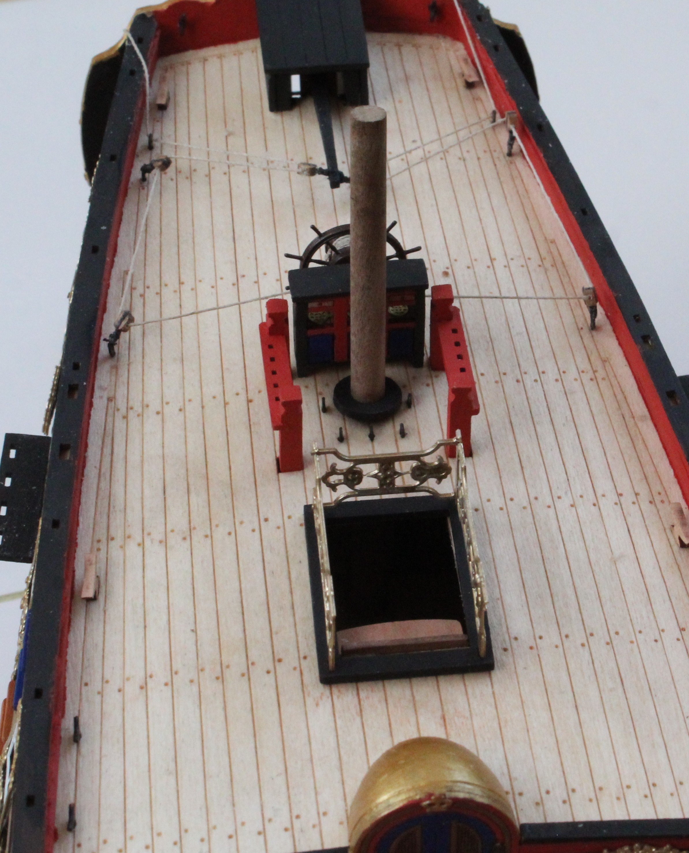
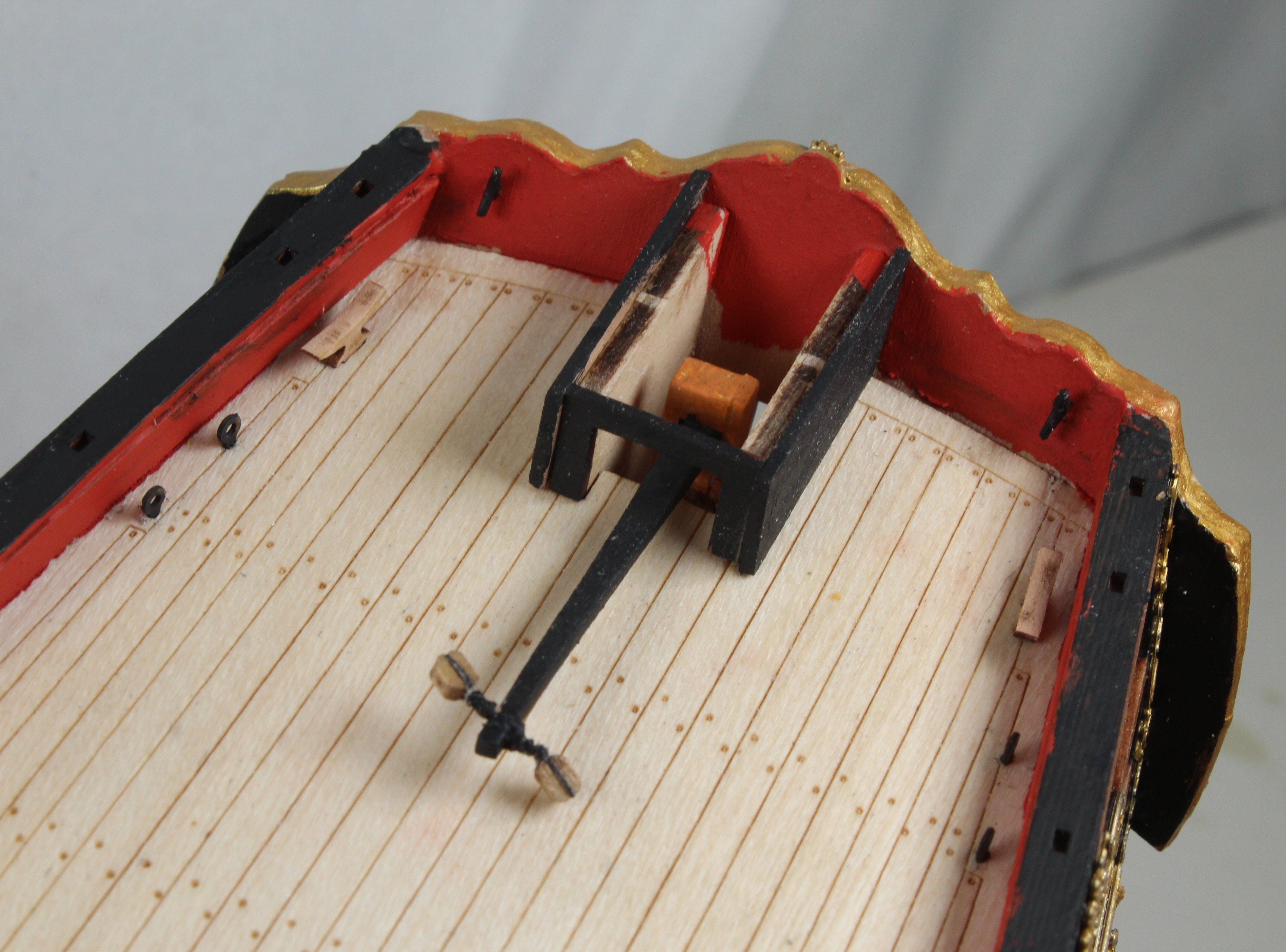
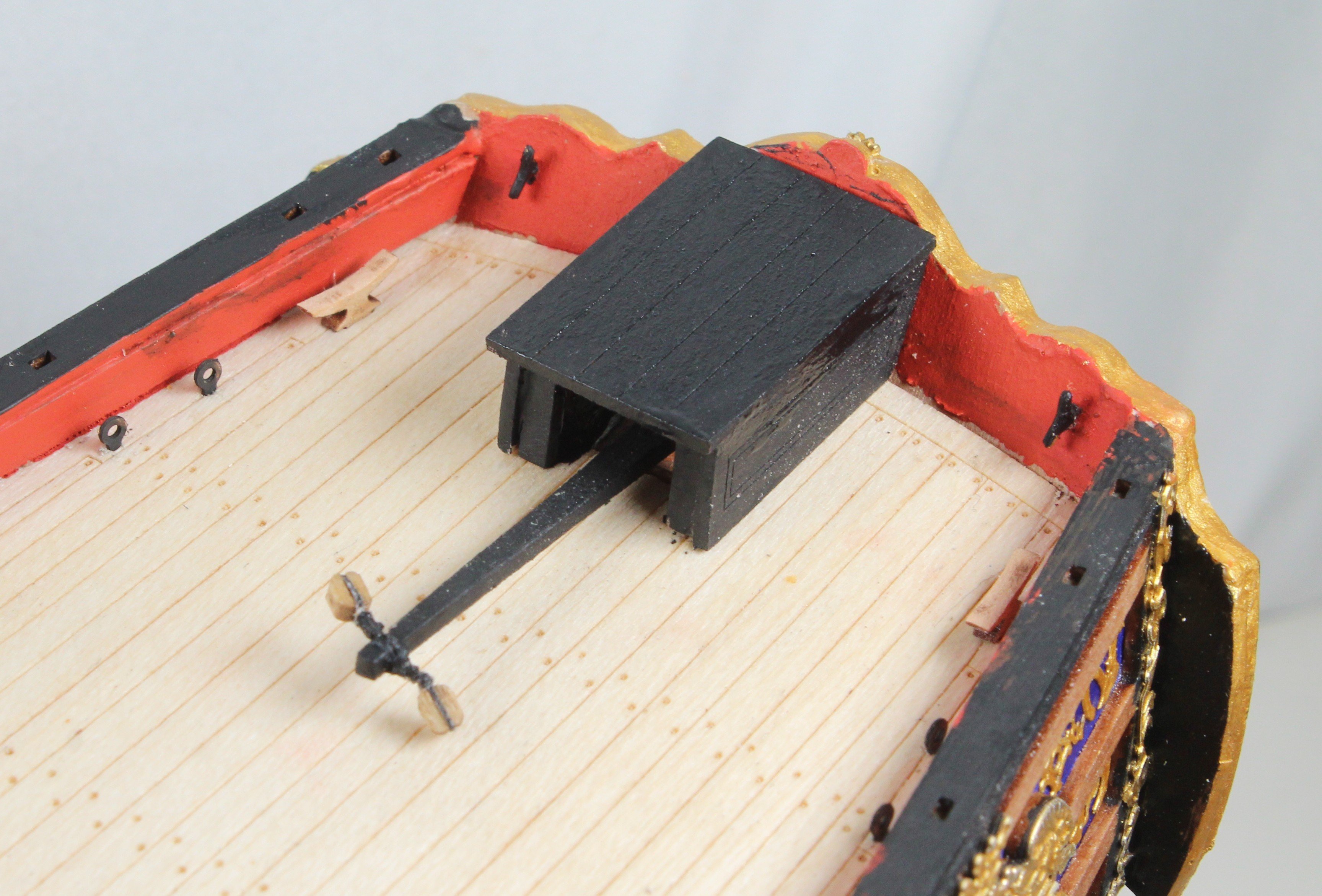
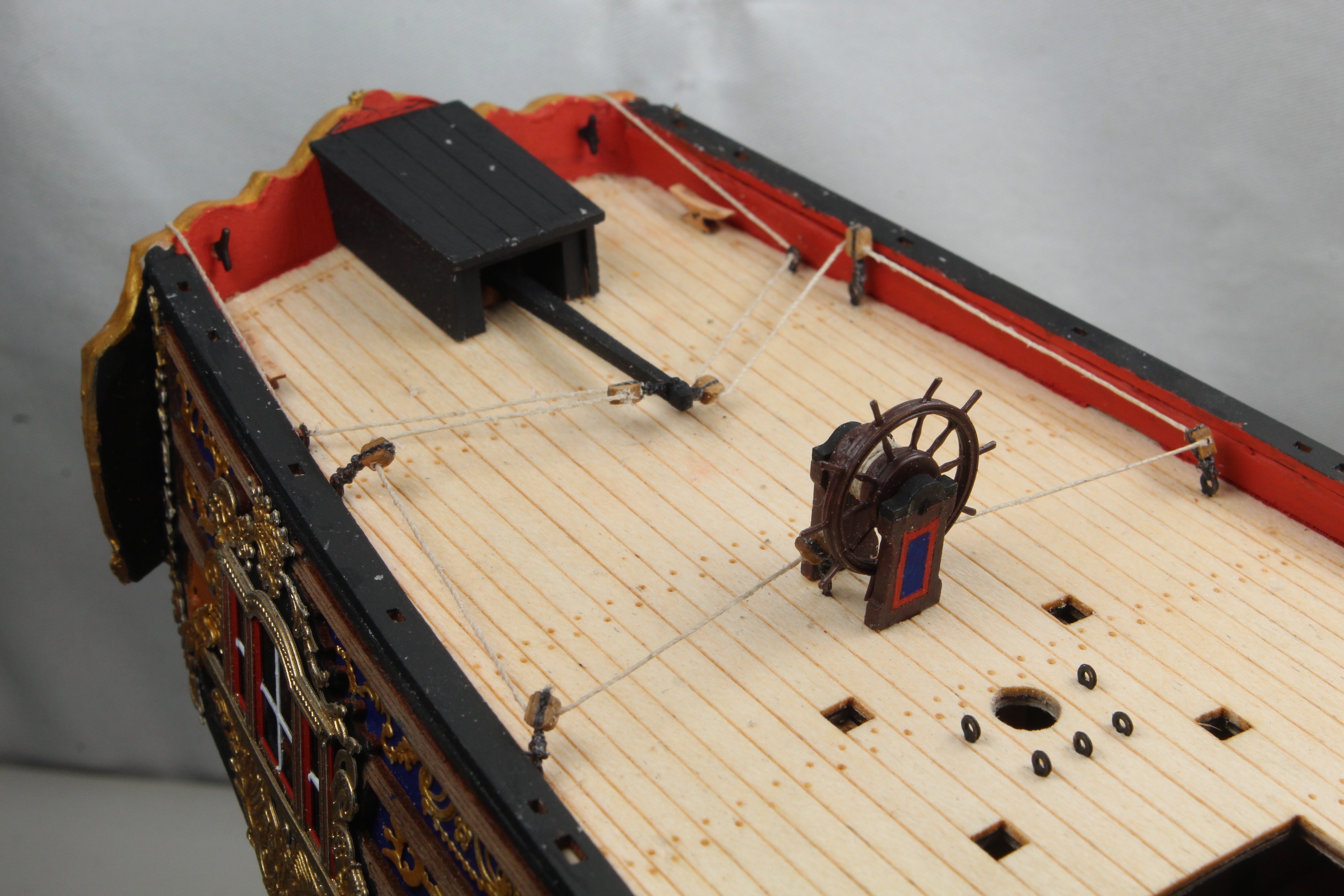
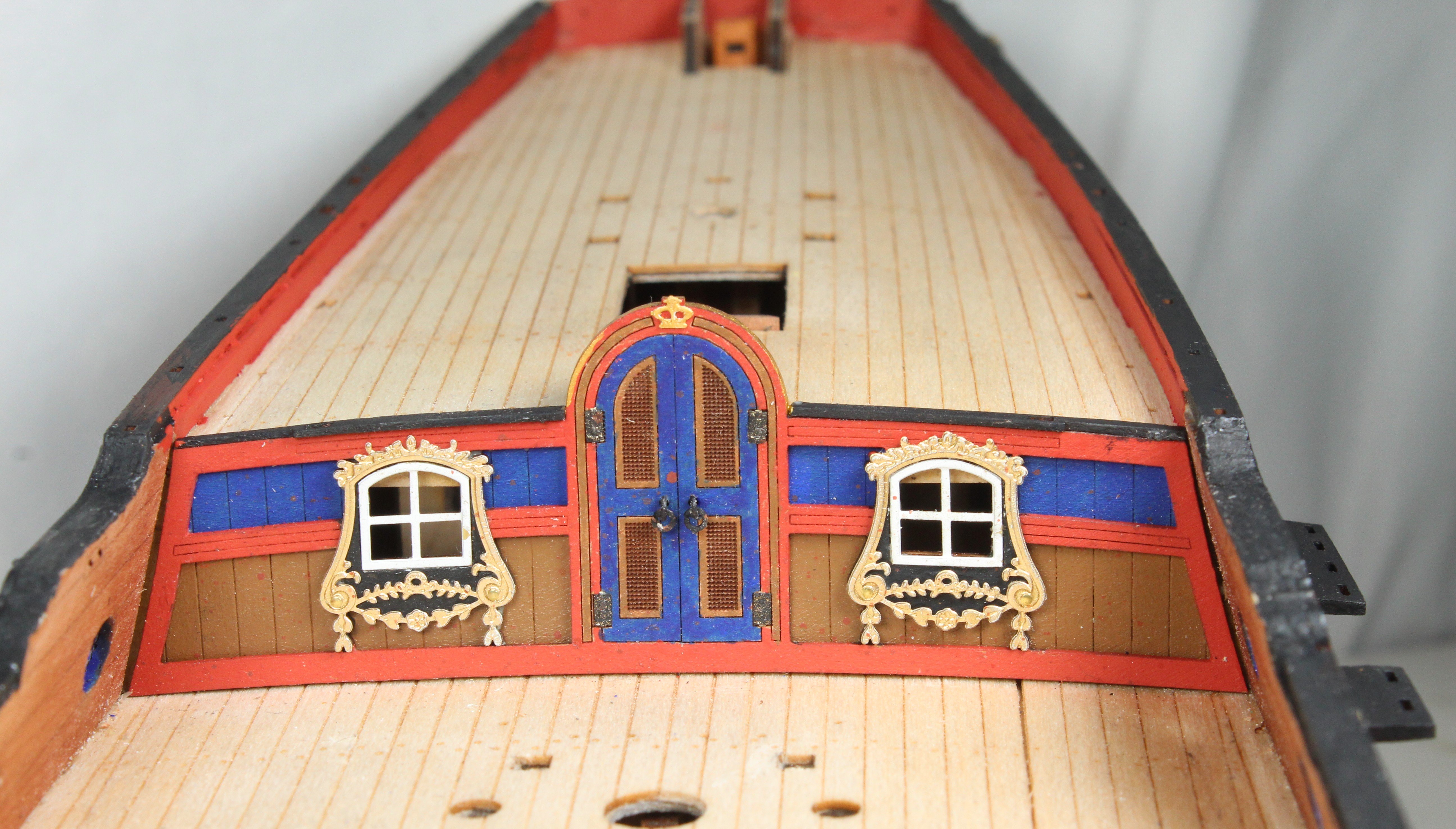
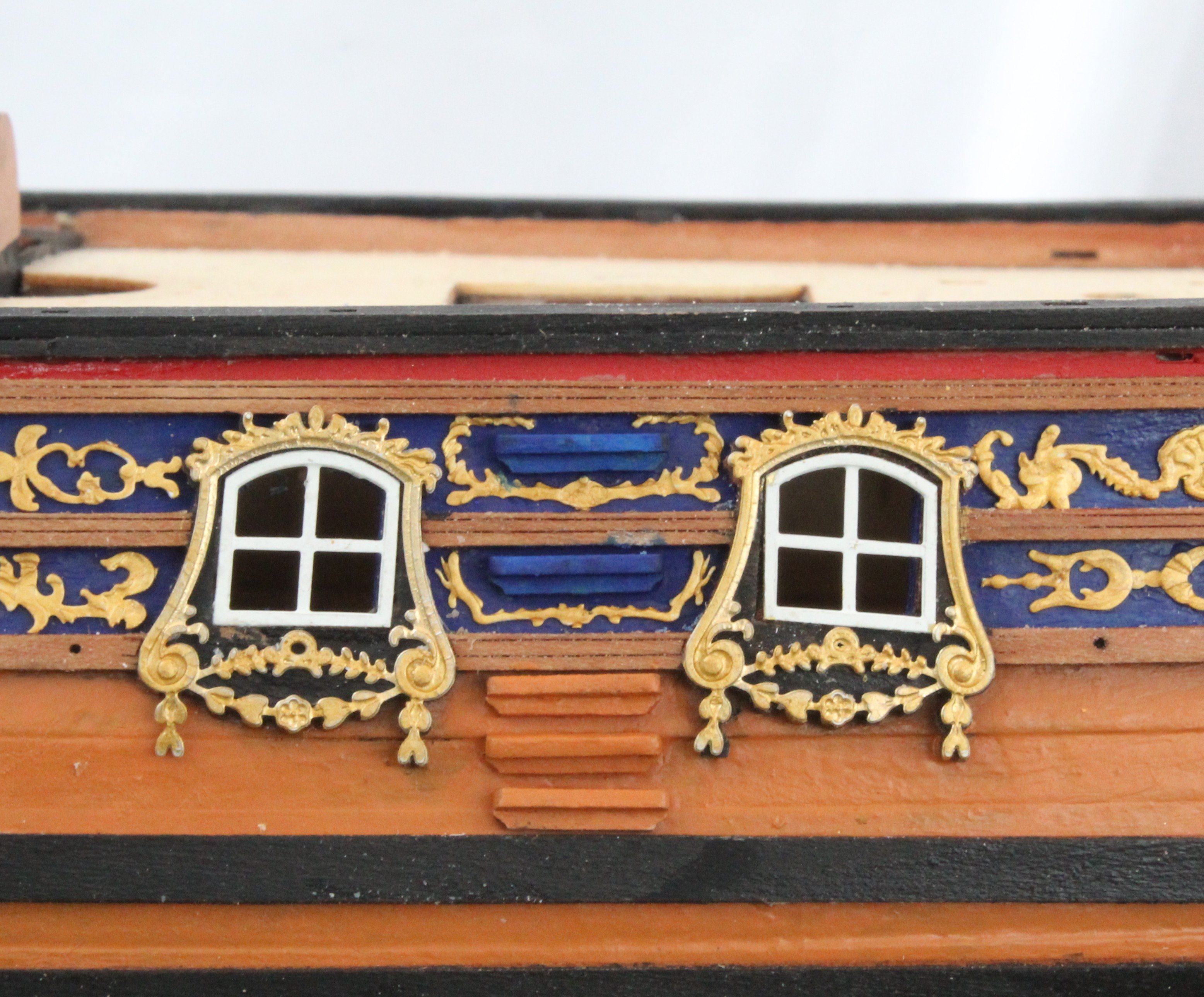
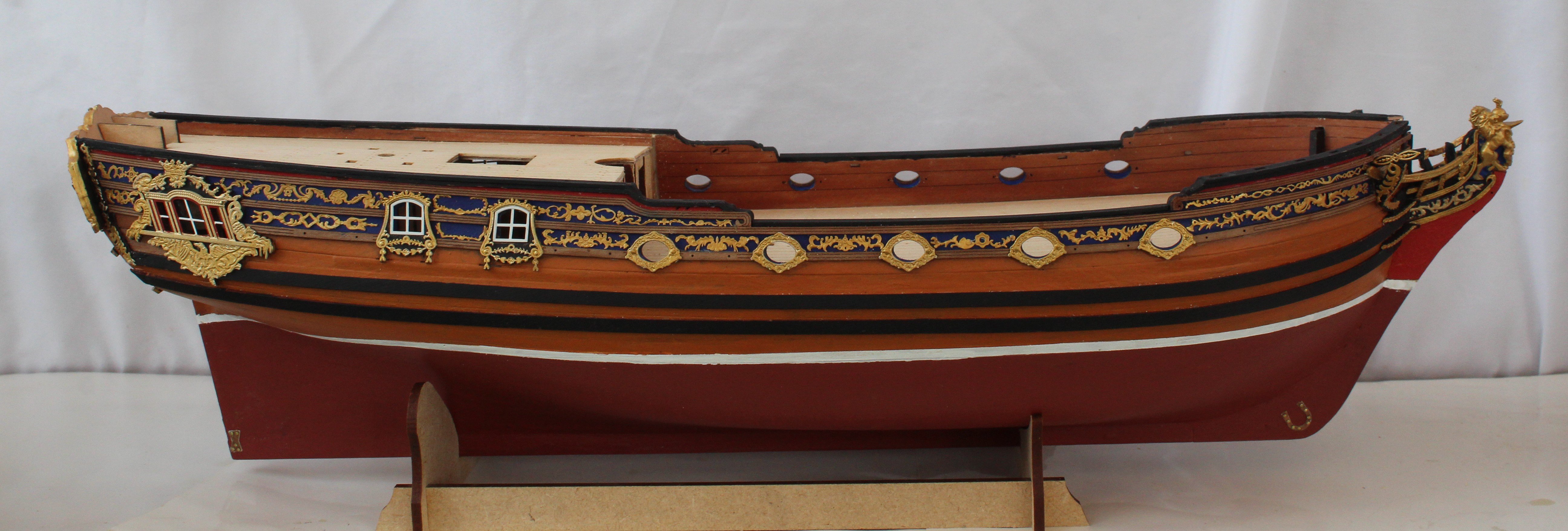
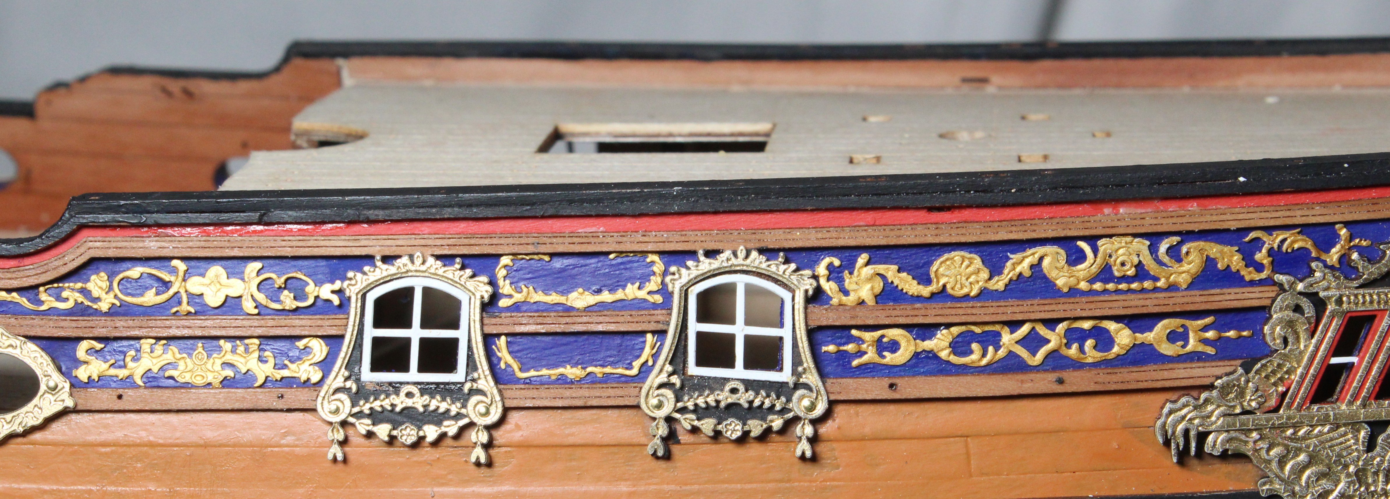
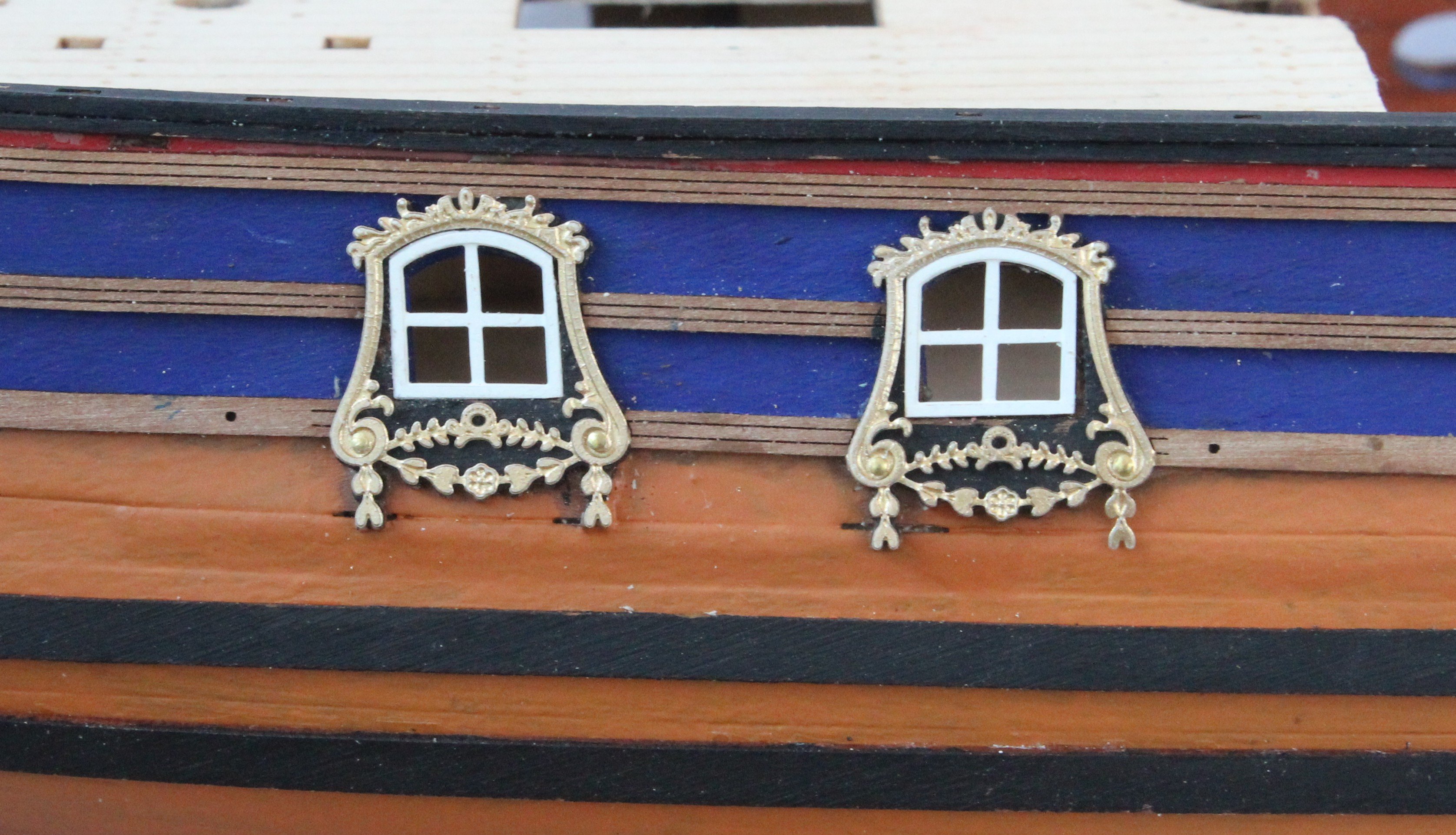
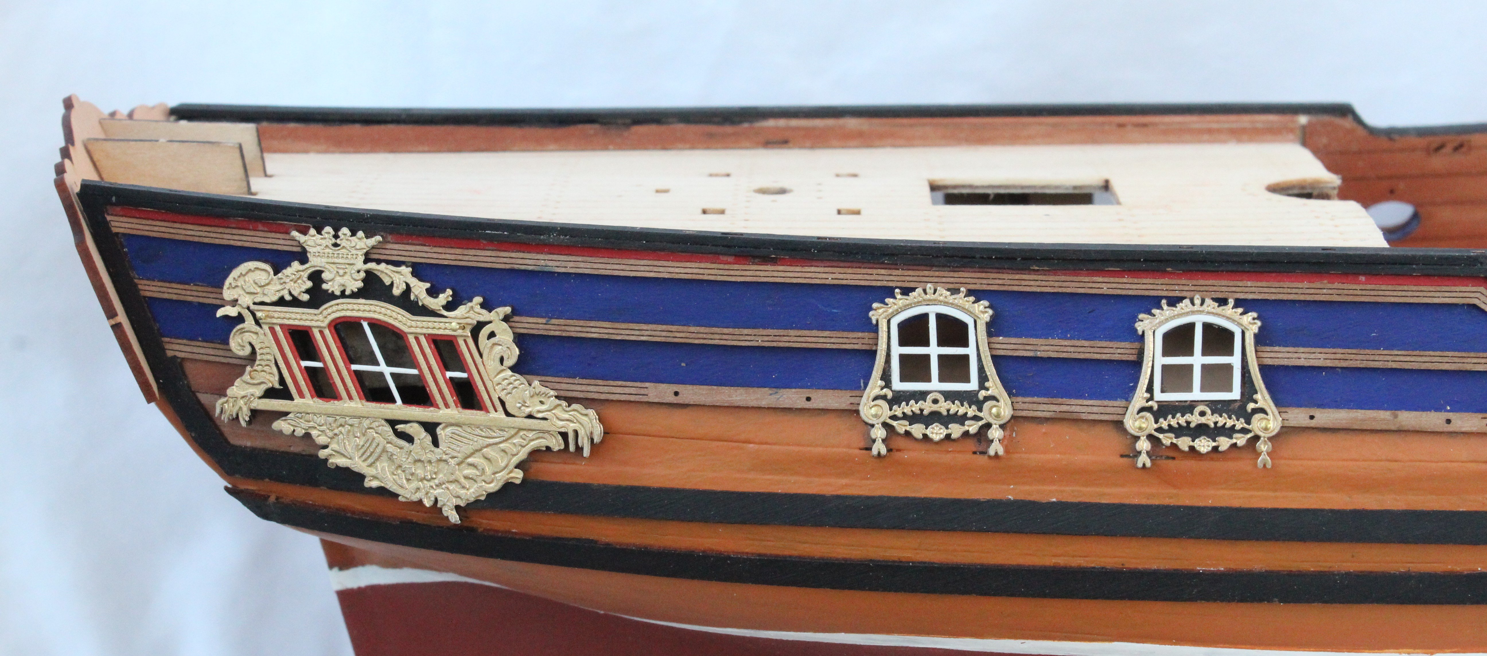
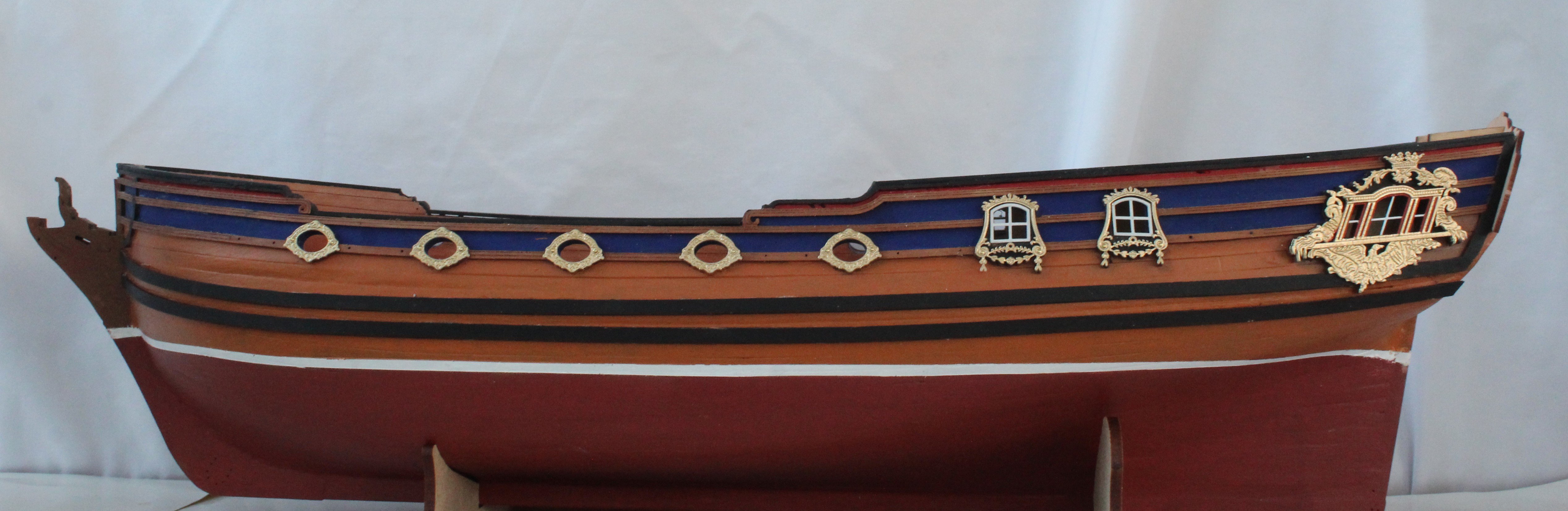
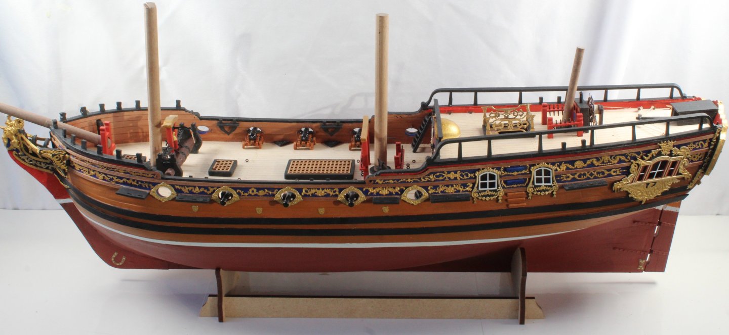
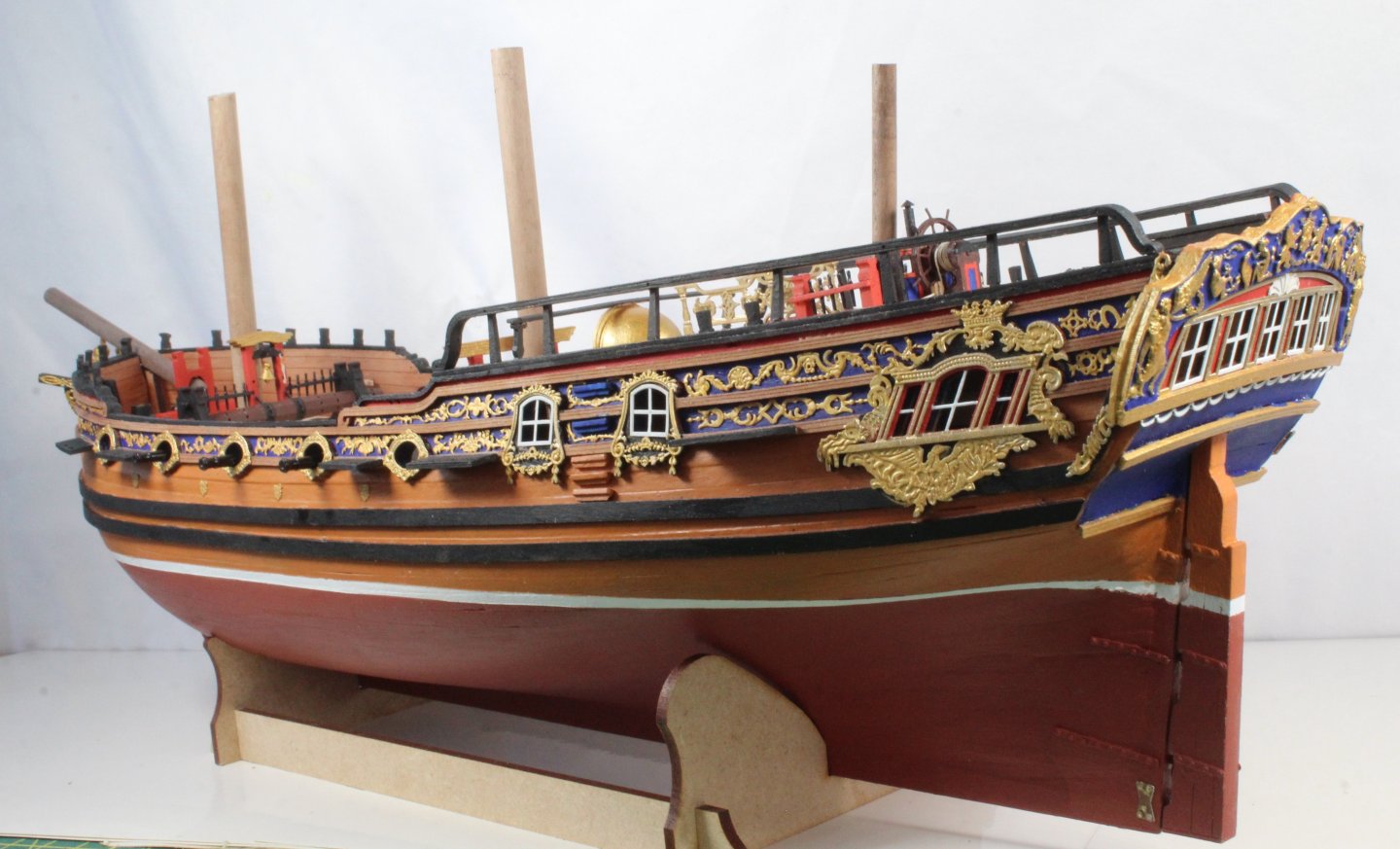
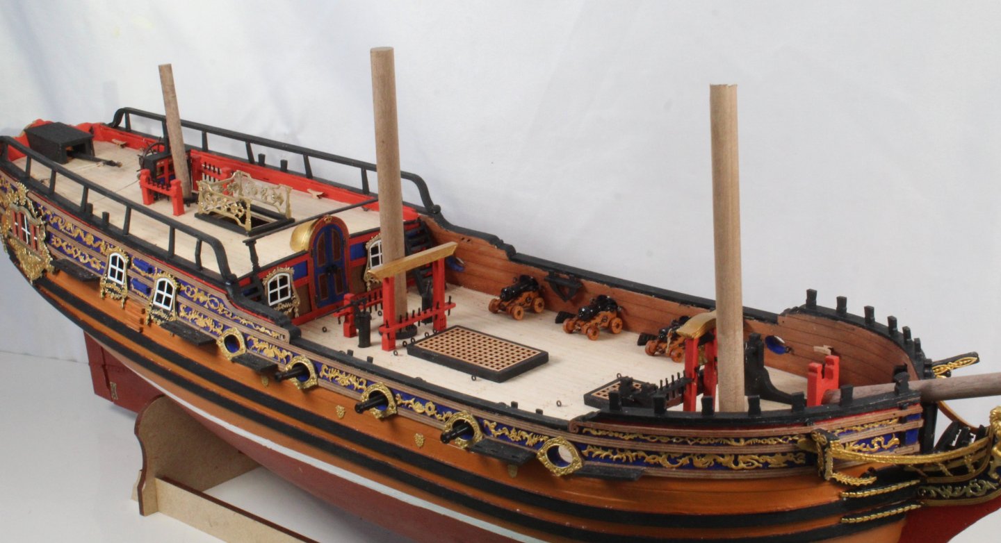
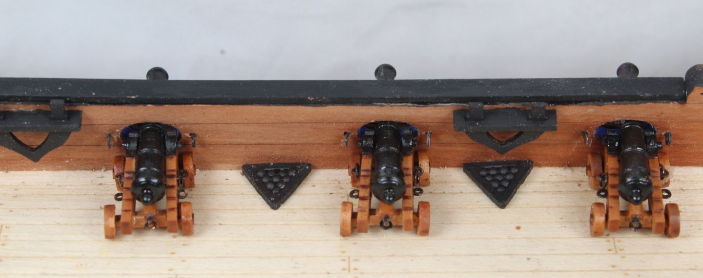
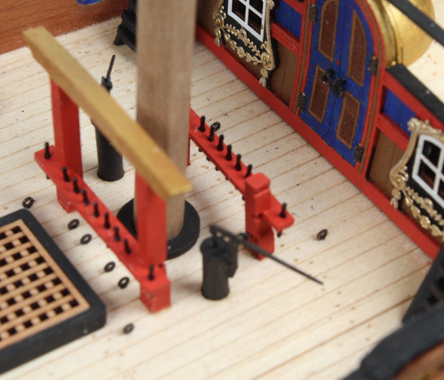
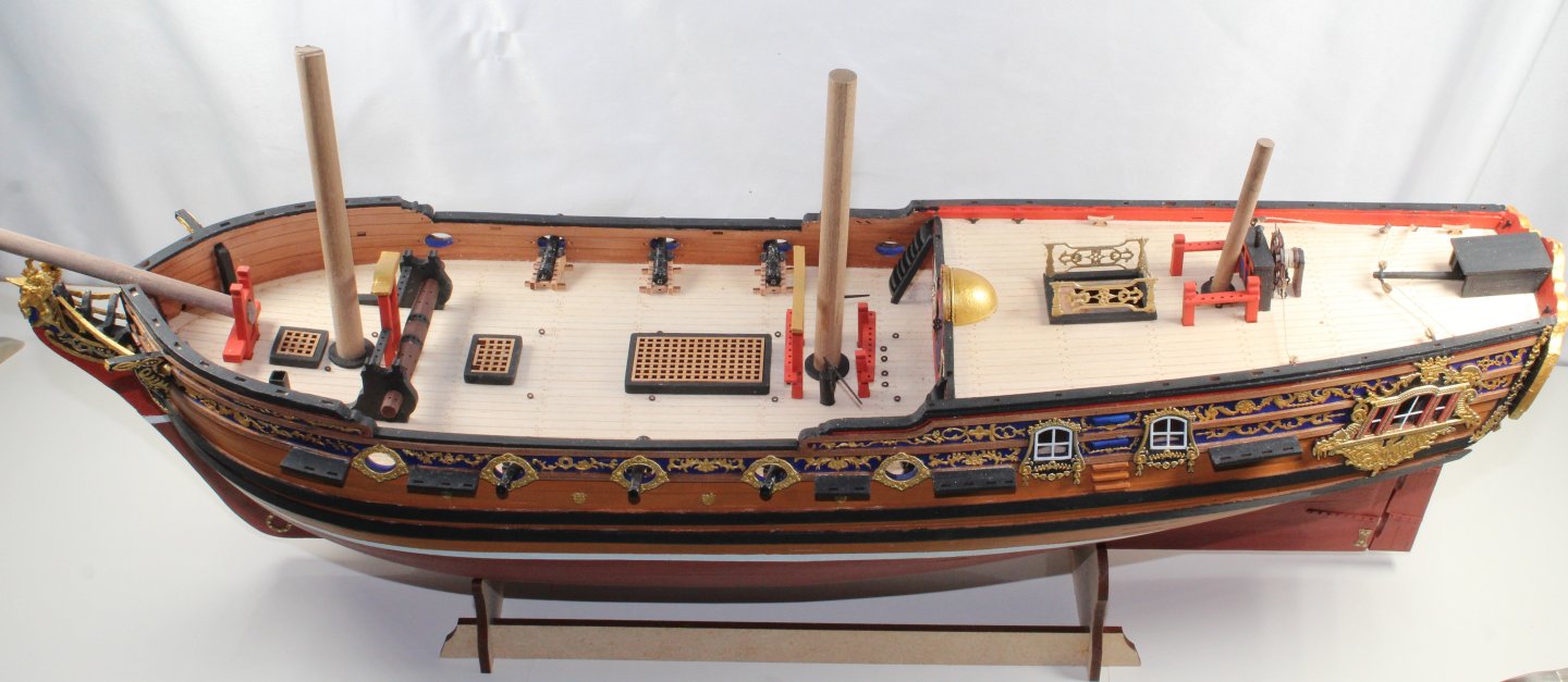
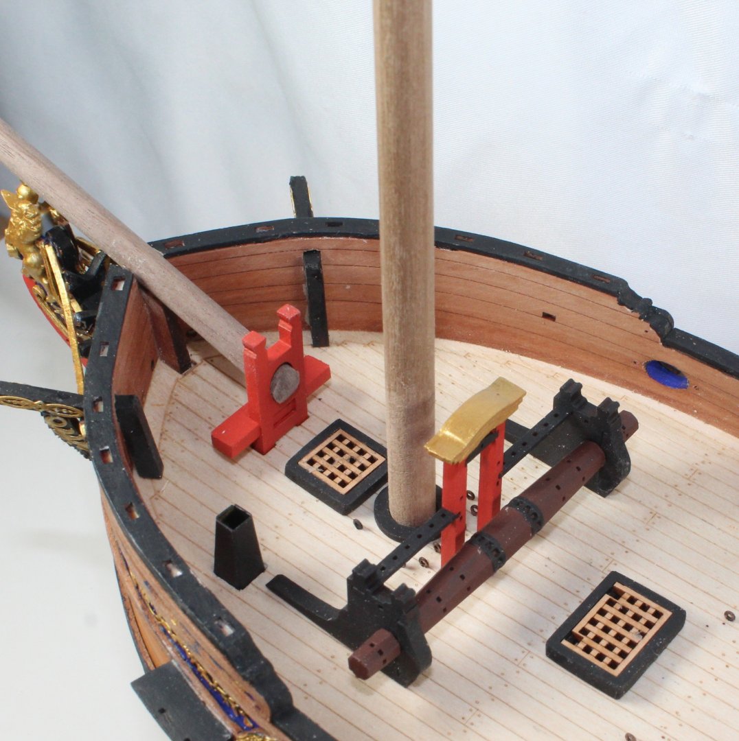
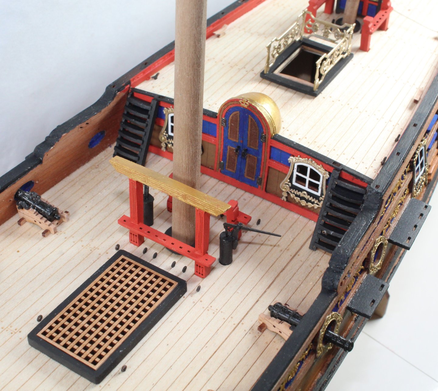
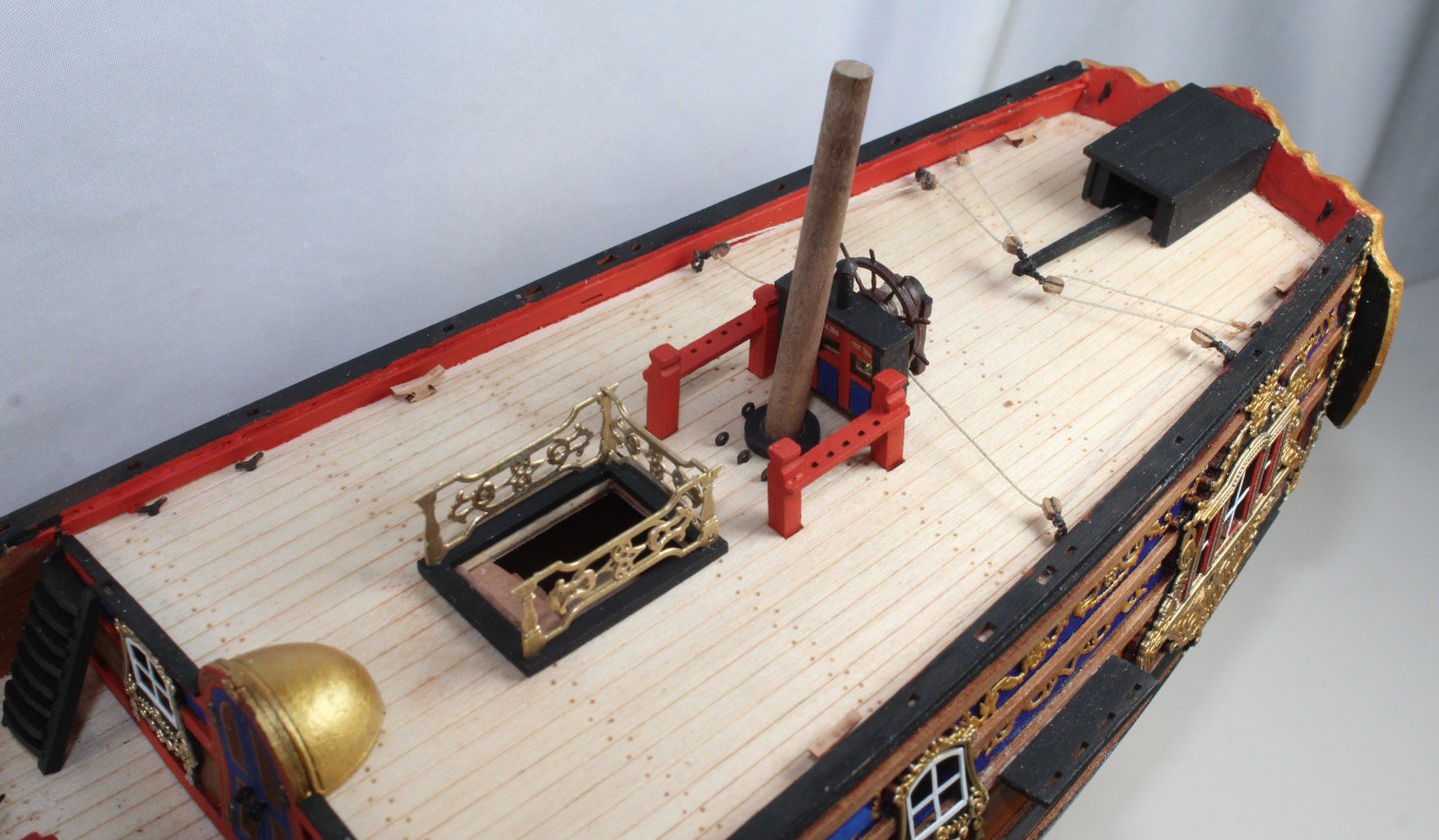
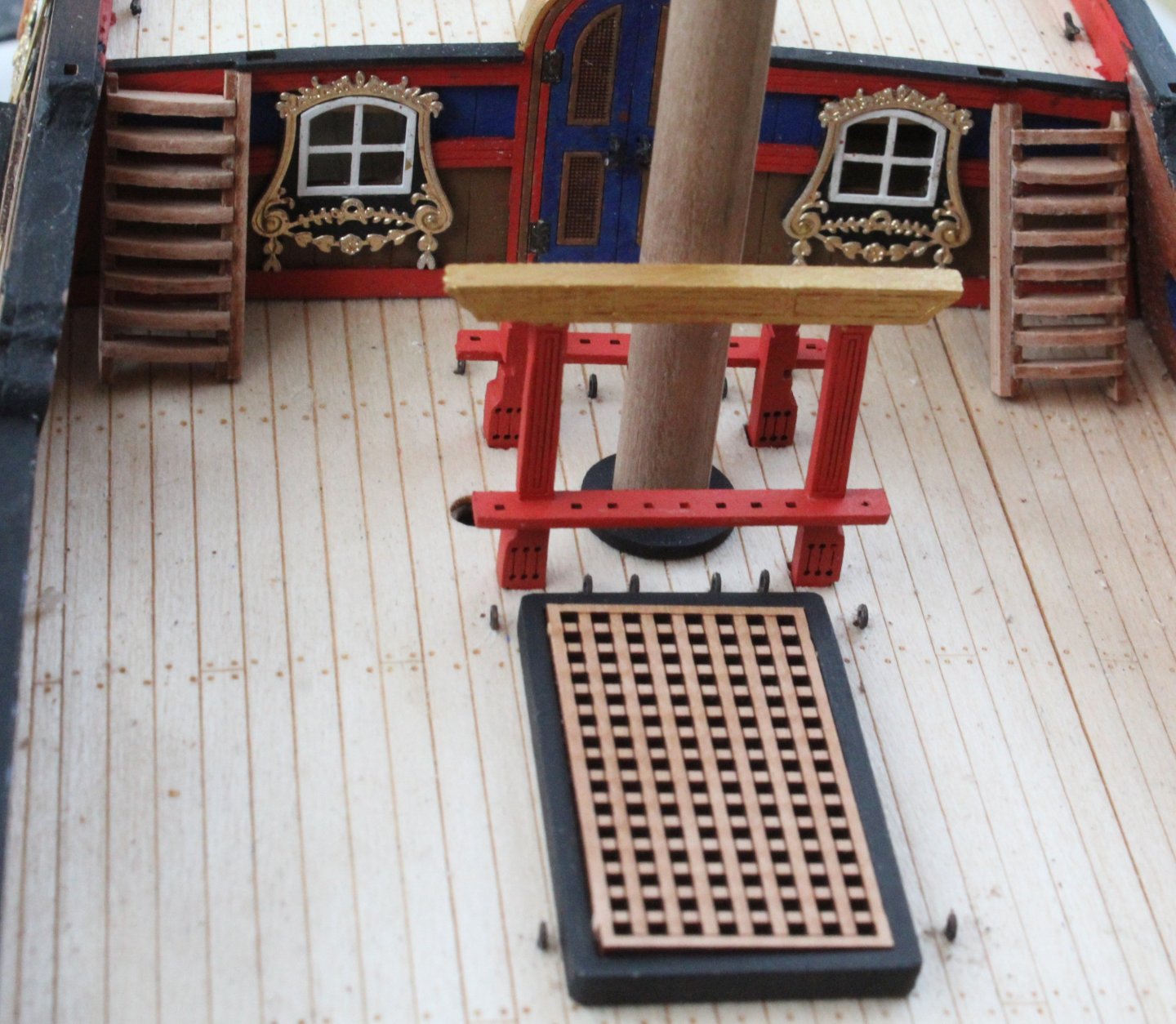
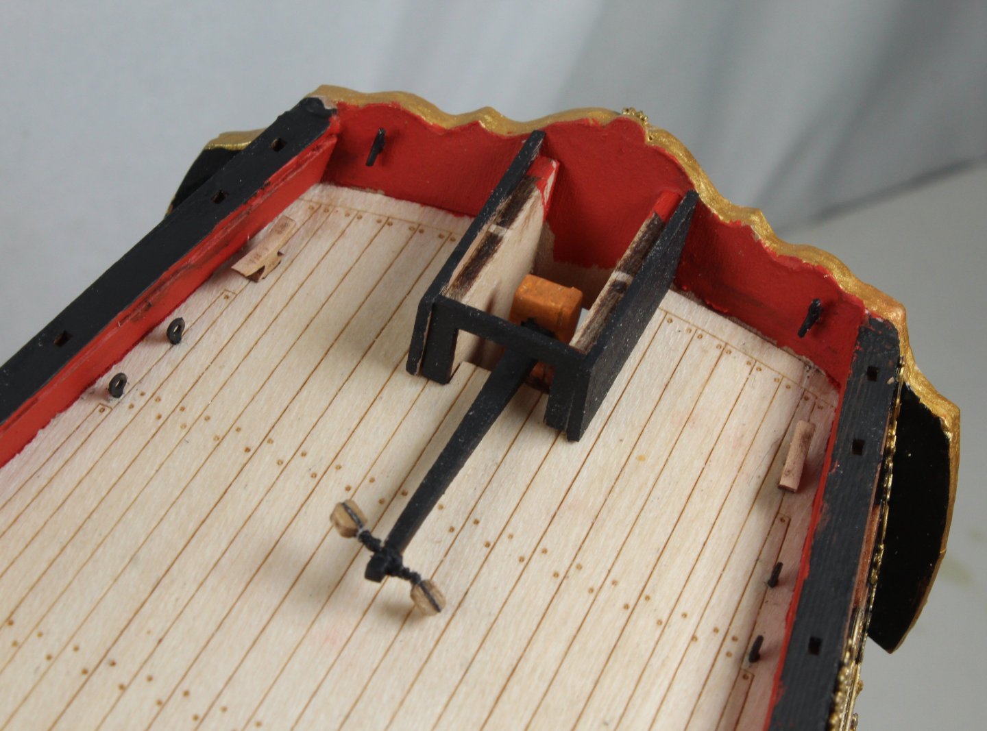
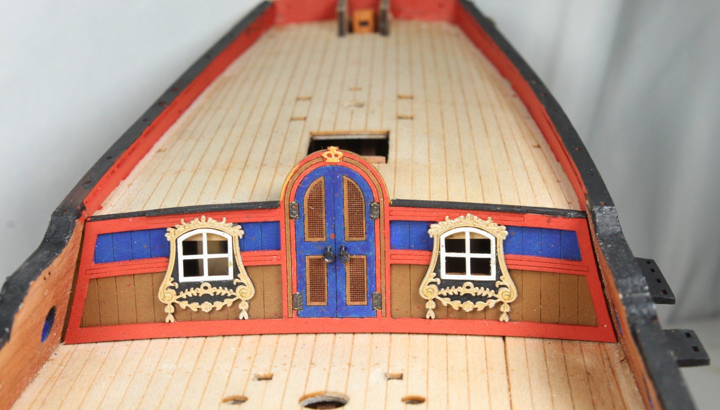
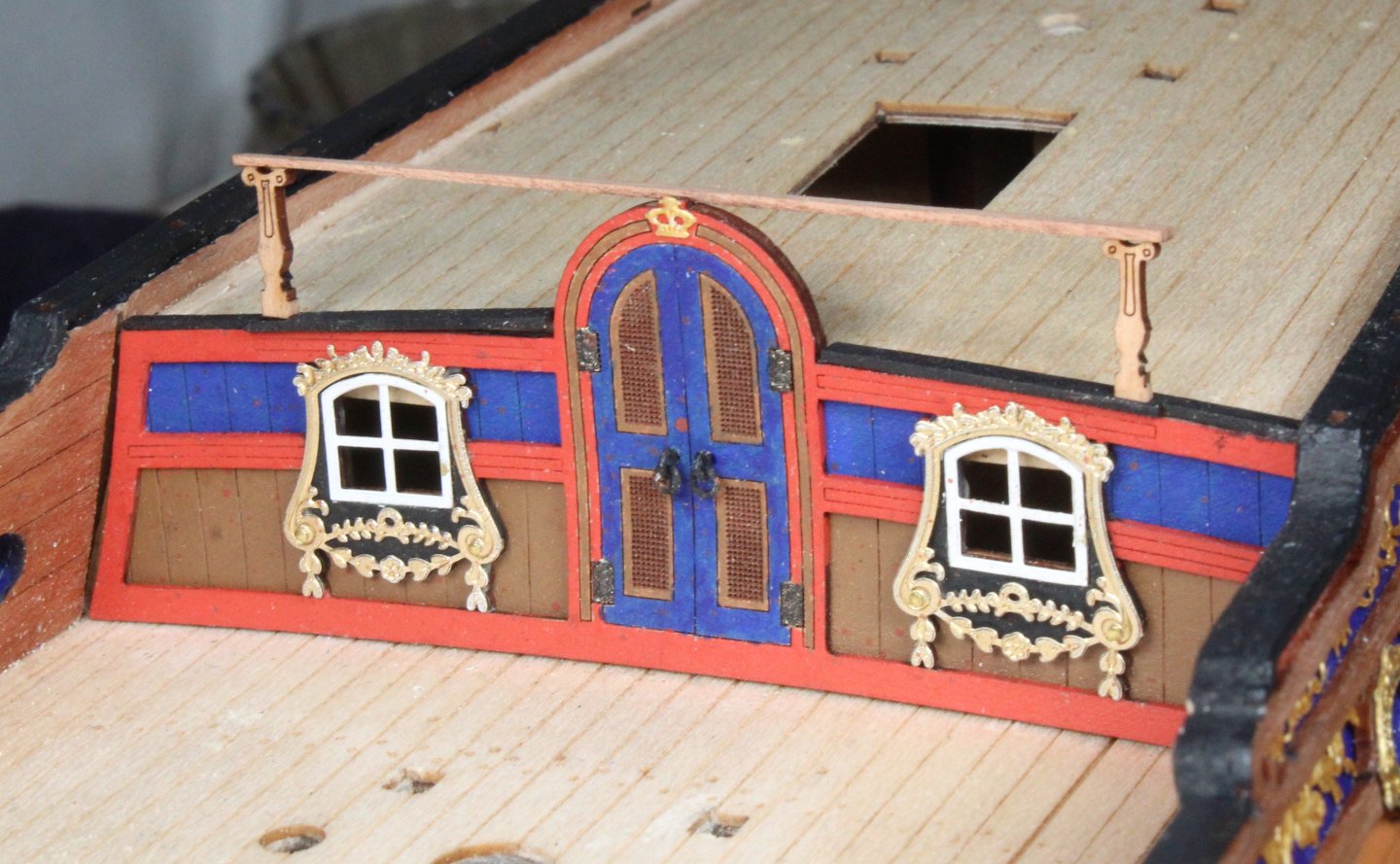
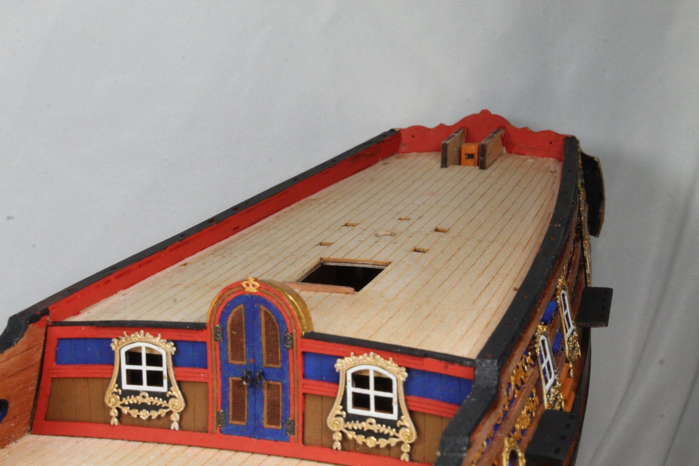
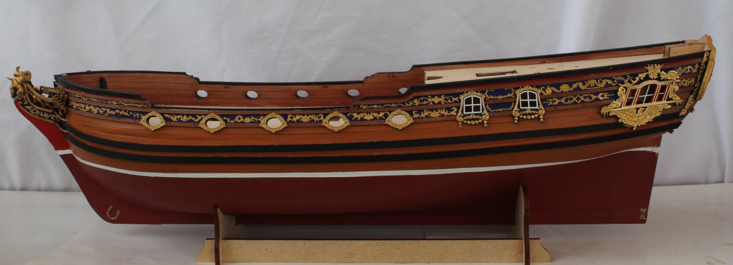
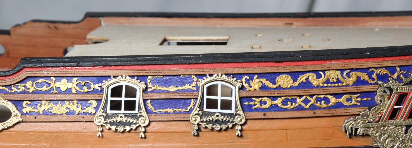
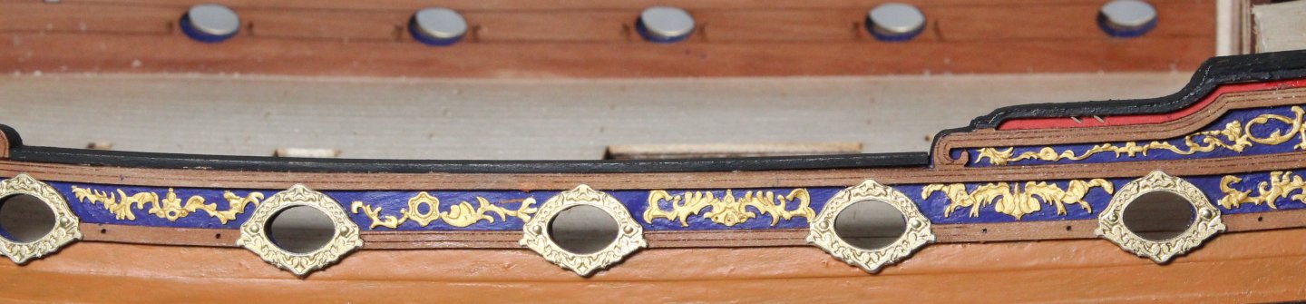
Build Log – Post 39 (20/01/26) Task 63 – Completing The Deck Work All the deck items have now been installed. SInce my last post I have added the belay pins to the various rack, the cannons have been added along with the shot garlands. The windlass assembly has been secured in place. Eyebolts added to all the gun ports. I have not added the channel deadeye strops / chain links as I normally do these when adding the shrouds so they can follow the same path. I did rig one of the cannons but then decided I preferred the unrigged version. I have started work the yard production and will add a post in due course. Photos Here is a selection of photos of the current build status. Lower Deck Upper Deck Stern Bow Deck Area Cannons and shot garlands Rear section of lower deck Upper Deck Mizzen Bitts with belay pins Decorative windows


-
Build Log – Post 38 (15/01/26) Task 62 – Fixing Deck Items Most of the deck items have now been fixed in place. I have managed to repair the ship’s chimney, but I will have to make a new base. There is still a little bit more work to do regarding the windlass assembly as the ships bell and some PE parts still need to be added. The ships wheel rigging has now been belayed and seized. The ships hand pumps have been assembled. The cannons have been placed on the deck, but the carriage wheels still need to be added. I am planning to rig the cannon. There a few staghorn cleats, shot garlands and eyebolts to add to the inner lower deck. Finally, the all the timberheads and the three upper deck hand rails will be added. #

-
Glenn-UK reacted to a post in a topic:
Grecian by DB789 - FINISHED - Vanguard Models - 1:64 - American Privateer Schooner
-
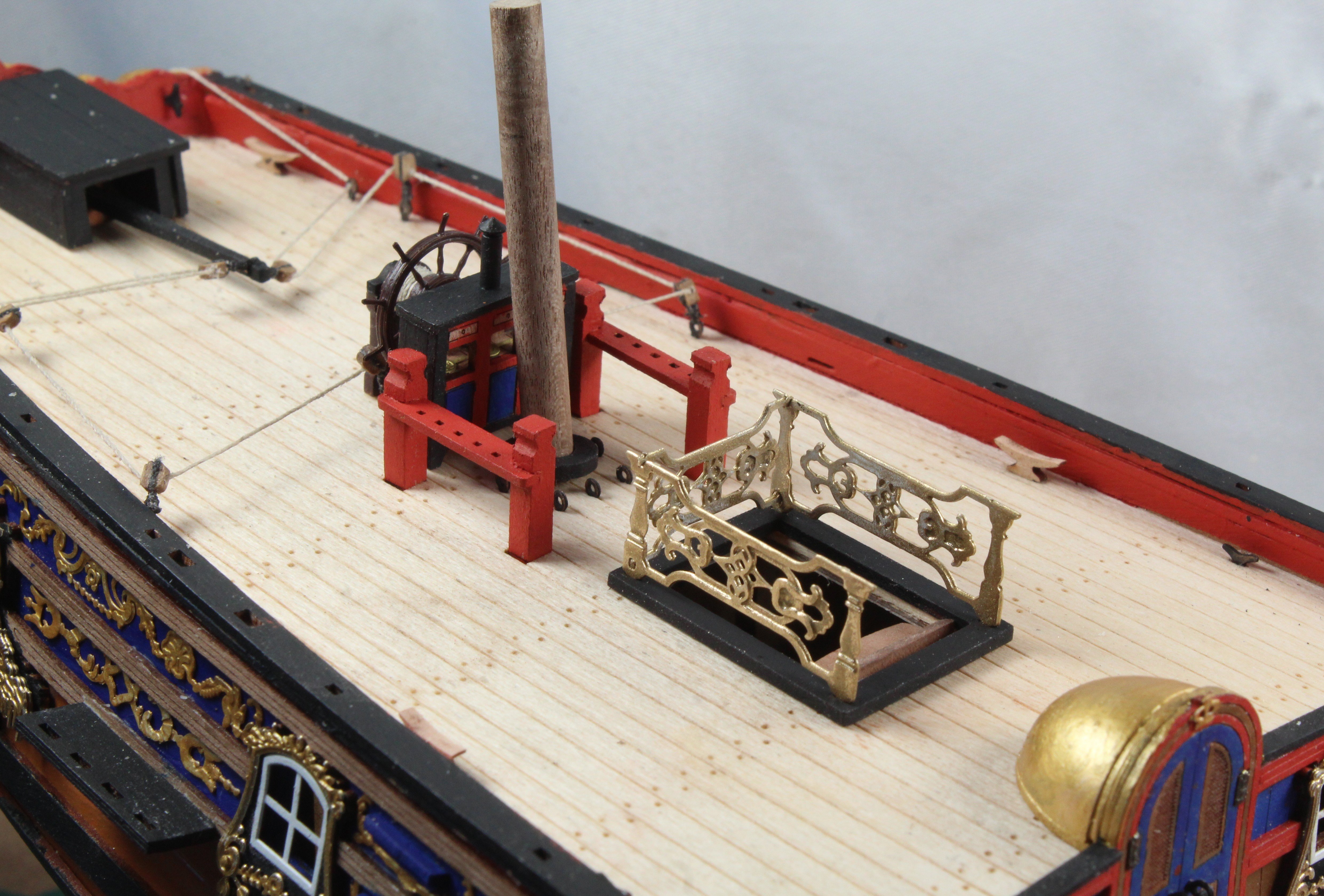
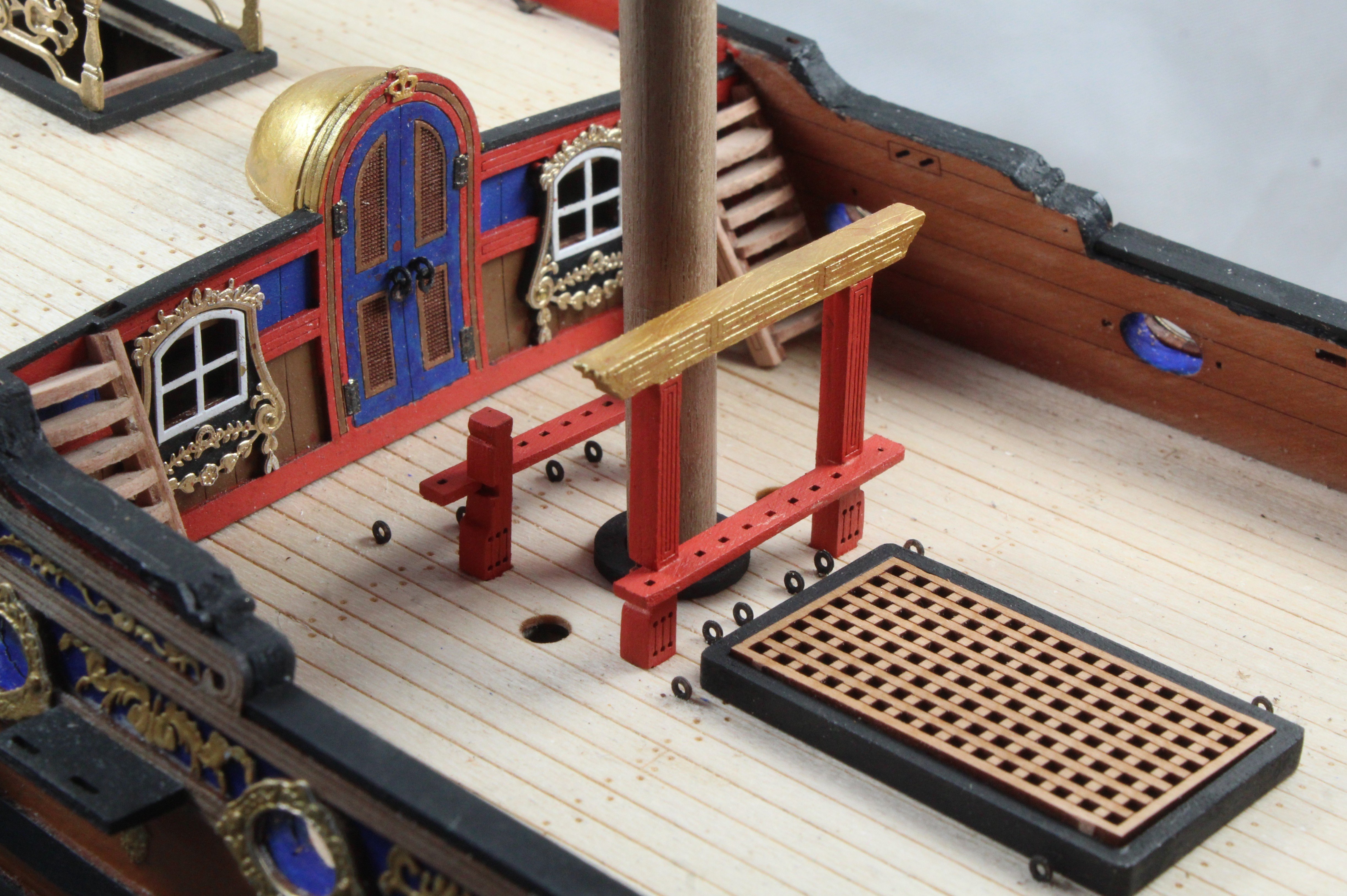
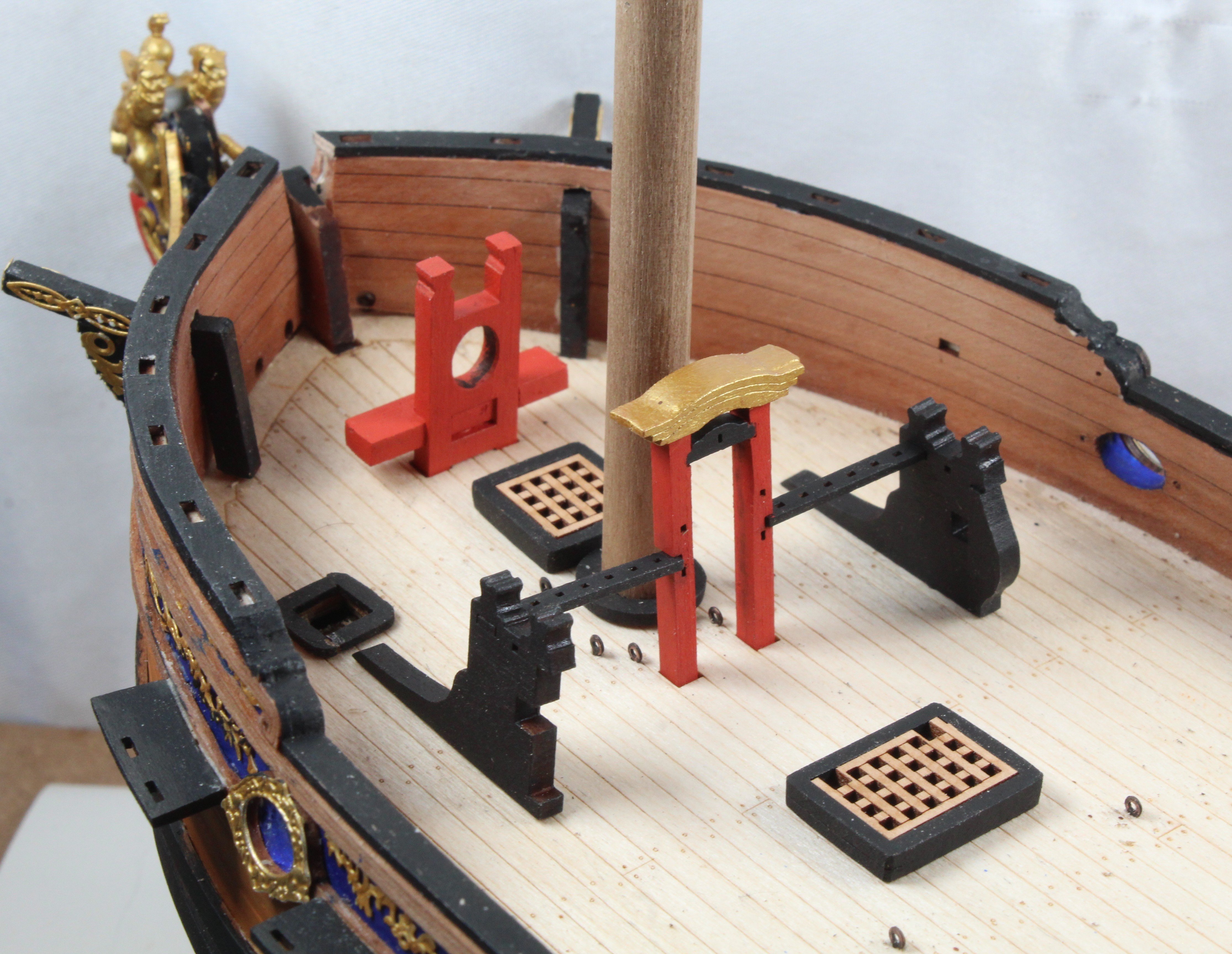
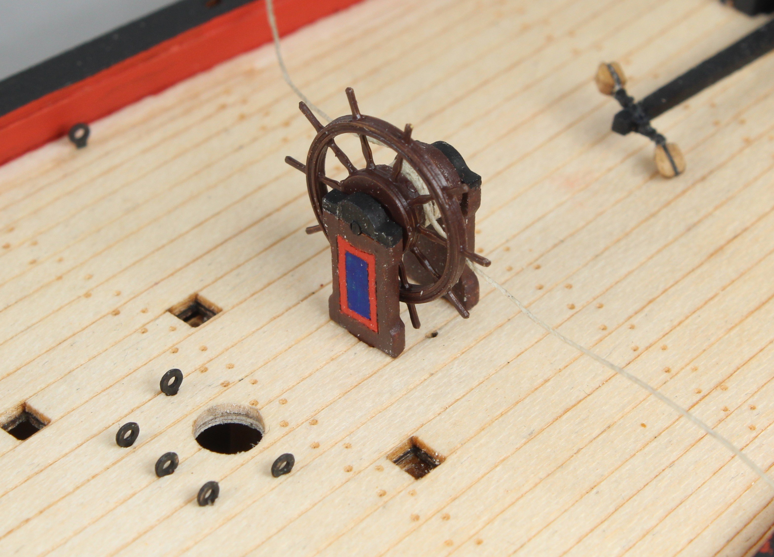
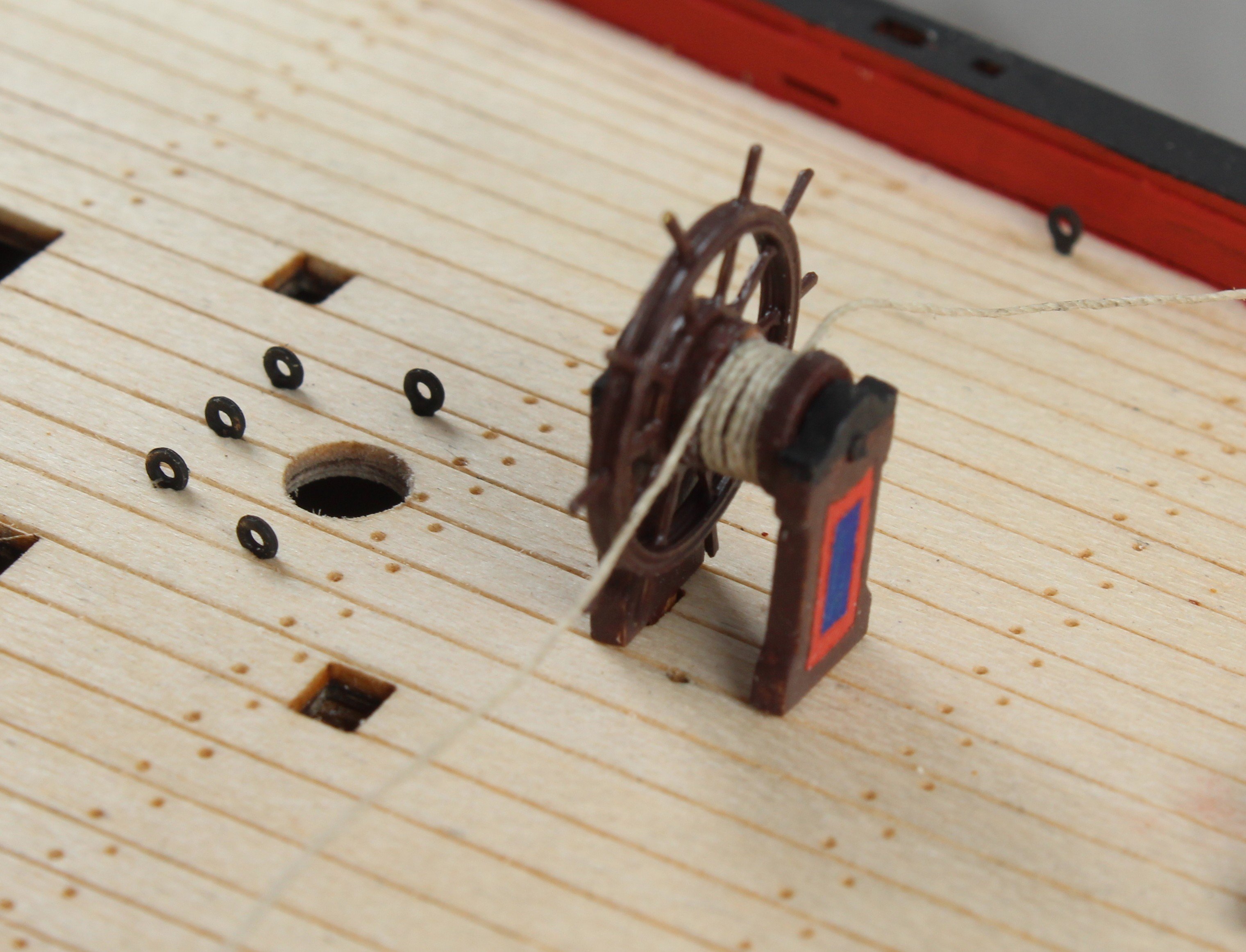
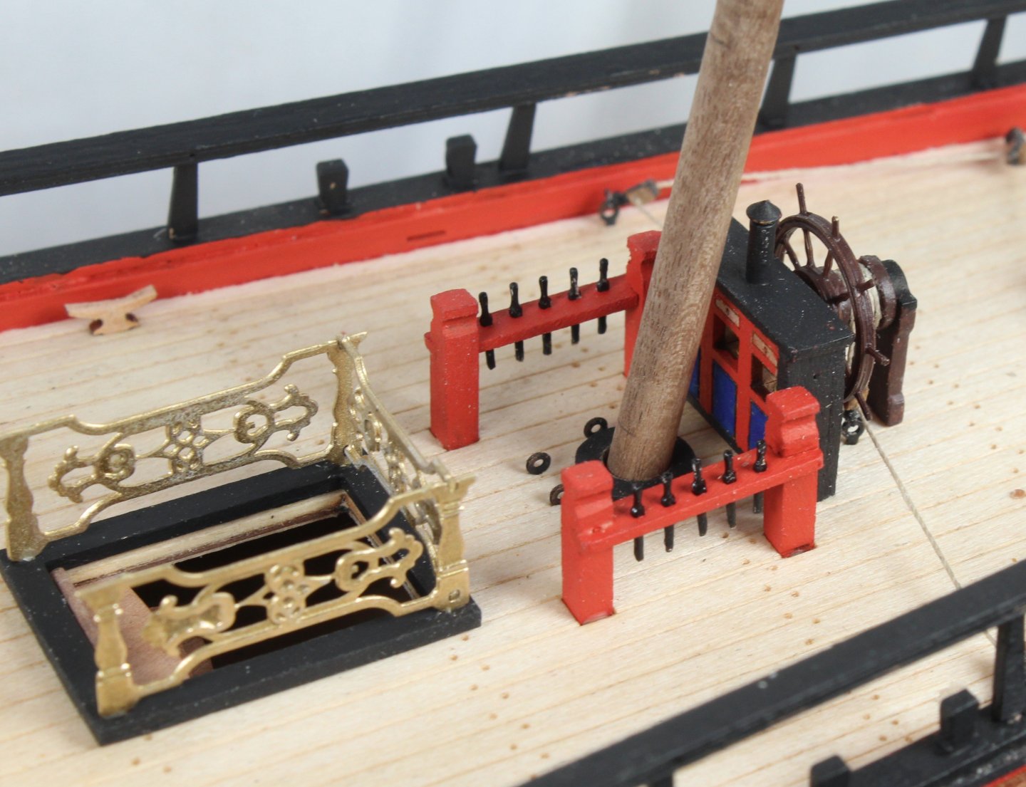
Build Log – Post 37 (14/01/26) Task 61 – Painting and Test Fitting Deck Items Starting with the upper deck items I gave some thought to the colour scheme I painted the binnacle in a similar manner to the ships wheel. The top section and side panels were painted black. The front and rear panels were painted with red bands and blue panel infills. The mizzen mast bitts were painted red. The mizzen mast base and upper deck spiral staircase coaming were painted black. The decorative PE quarterdeck companion rails were painted gold, These items were then test fitted, and I am happy with how they look. Moving on to the lower deck items I decided to paint both the gallows and main mast bitts red and then added a gold finish to the top section of the gallows bitts. The various coamings were painted black. I painted the belfry assembly red with a gold colour top section and black for the ship’s bell head stock. The bowsprit bitts were painted red. The windlass bitts were painted black along with the main and fore mast bases. I have painted the windlass a nice wooden colour, but more work is required as I need to add the black bands. I did notice that one end section of the windlass was detached when I removed the part from box. I have pinned and glued the parts together so hopefully all will be OK (right-hand end in the photo below). I also have to paint and assemble the two hand pumps. When folding the ships stove chimney the PE part sheered along the fold line. I also managed to break the chimney coaming. I have a couple of ideas to solve this problem.


-
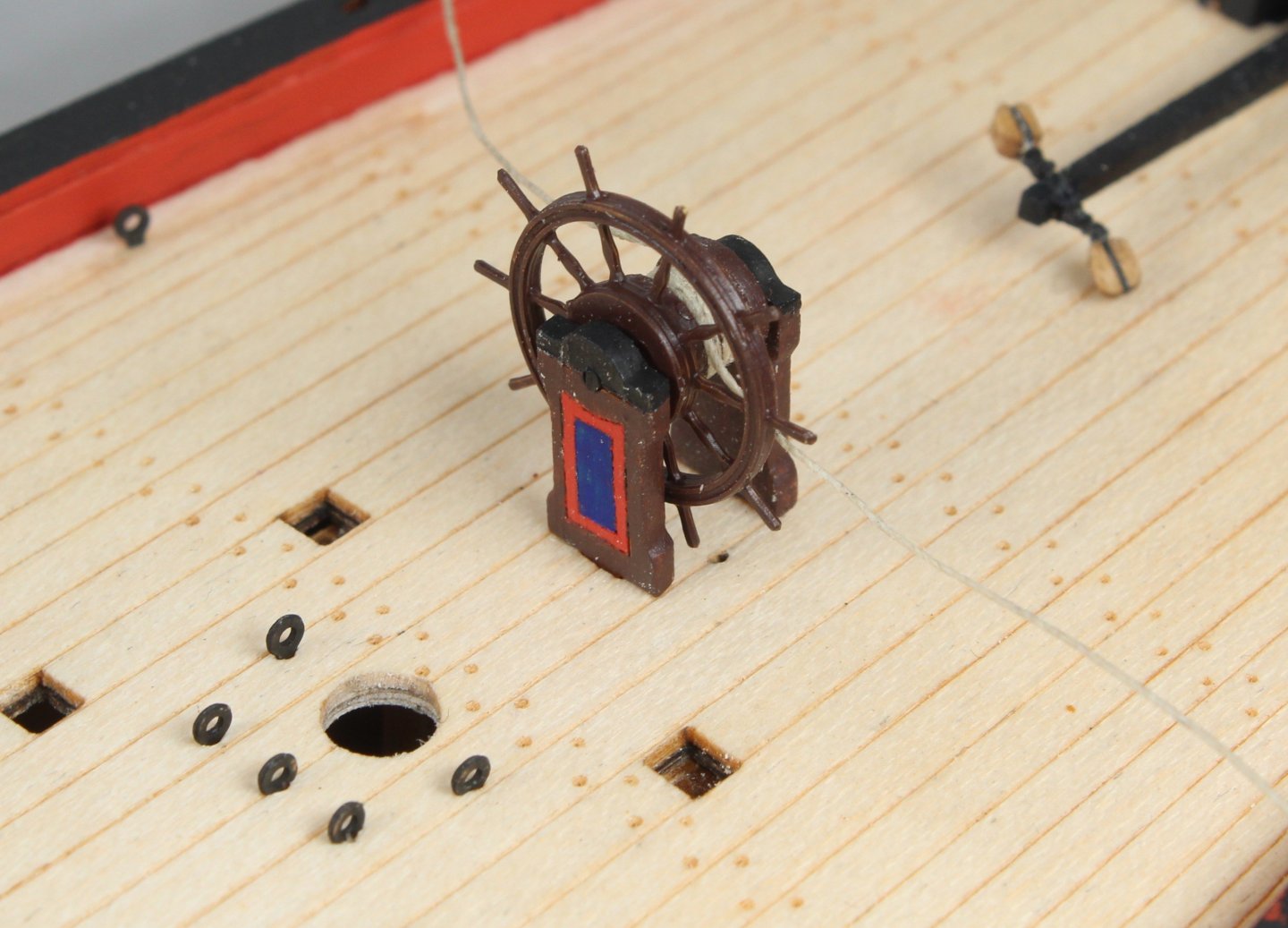
Build Log – Post 36 (13/01/26) Task 60 – Tiller Housing, Tiller and Ships Wheel The various parts of the tiller housing were painted black. The front and two side patterns were then glued in place. Next the tiller was painted black and two 2mm single blocks were added. The tiller was then glued in place. The tiller housing roof was then glued in place. A length of 0.25mm natural thread was wrapped around the ships wheel drum. Once that was done the ships wheel assembly was added to the upper deck. 6 off 2mm single blocks were then seized to eyebolts. Three blocks per side, complete with eyebolts, were then threaded to the ships wheel rigging. The eyebolts were then inserted in their respective locating holes on the upper deck, and the ships wheel thread was then tensioned. The two free ends of the ships wheel rigging still needs to be belayed to their respective eyebolts.


-
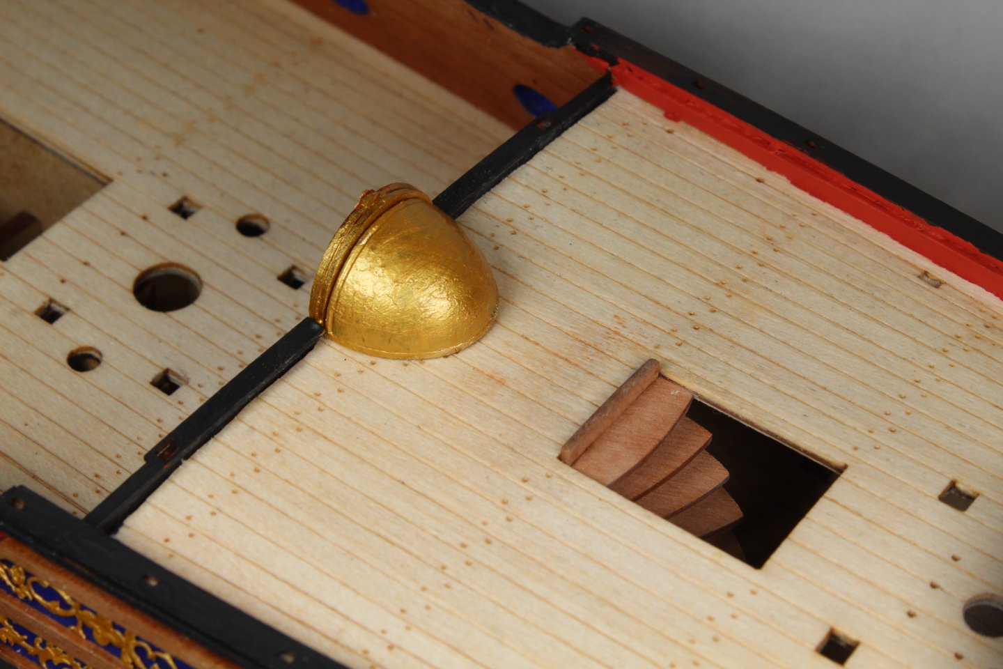
Build Log – Post 35 (12/01/26) Task 56 – Cabin Bulkhead Installation The cabin bulkhead had previously been assembled and painted. It was a simply task to glue this assembled part in place. With the bulkhead in place I did a test fit of the rail assembly. This will be fitted later on in the build. I decided to paint the upper deck inner bulwarks red. I think this enhances the upper section. I will paint the rudder housing assembly black which will add a nice contrast, once fitted. Task 57 – Hull Steps There are 5 steps per side hull which were glued in place. I decided to paint this steps the same colour as the hull. Task 58 – Channels There are 5 channels required per side. Each channel was carefully lined up with the locating holes on the hull. I marked the channels with the position of the holes and drilled holes. These were then fitted with small 0.5mm brass pins and test fitted. The front rails were then glued to the front edge of their respective channels. Once that was done the channels were painted black and then glued in place. Task 59 – Spiral staircase and Domed Canopy The domed canopy base was glued to the 3-D printed domed canopy. The assembly was then painted gold before it was glued in place. The previously assembled spiral staircase was also glued in place.


-
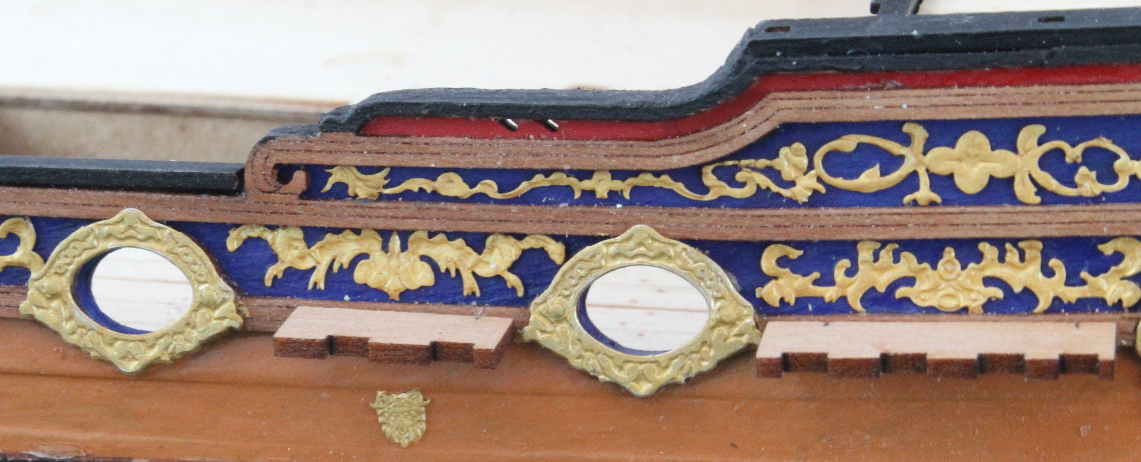
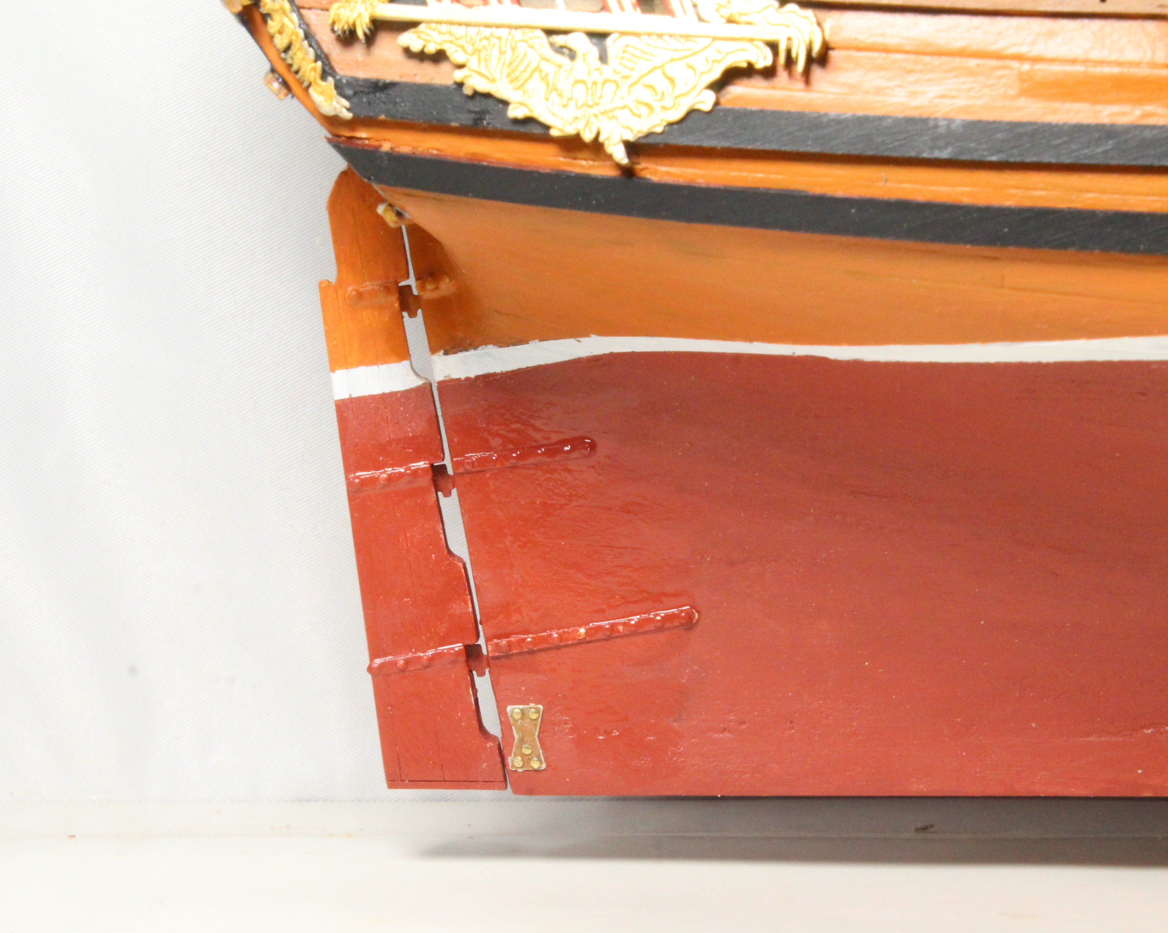
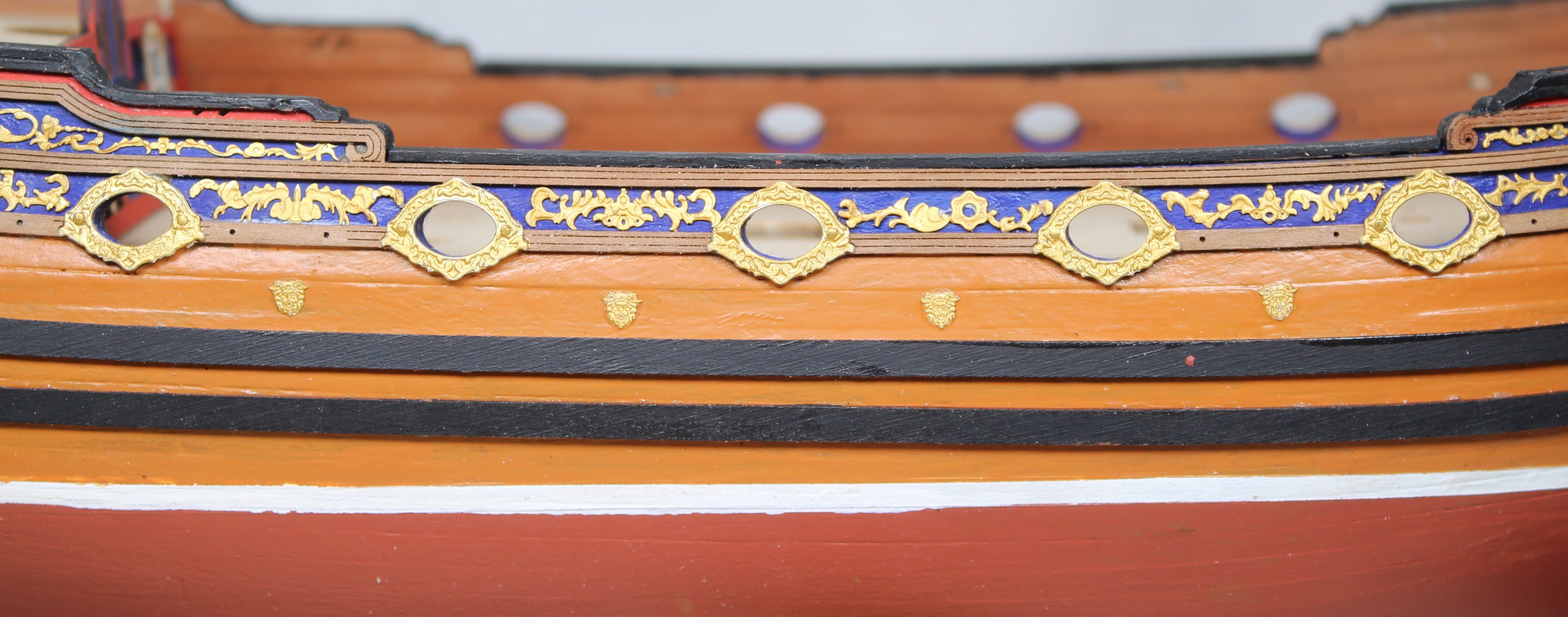
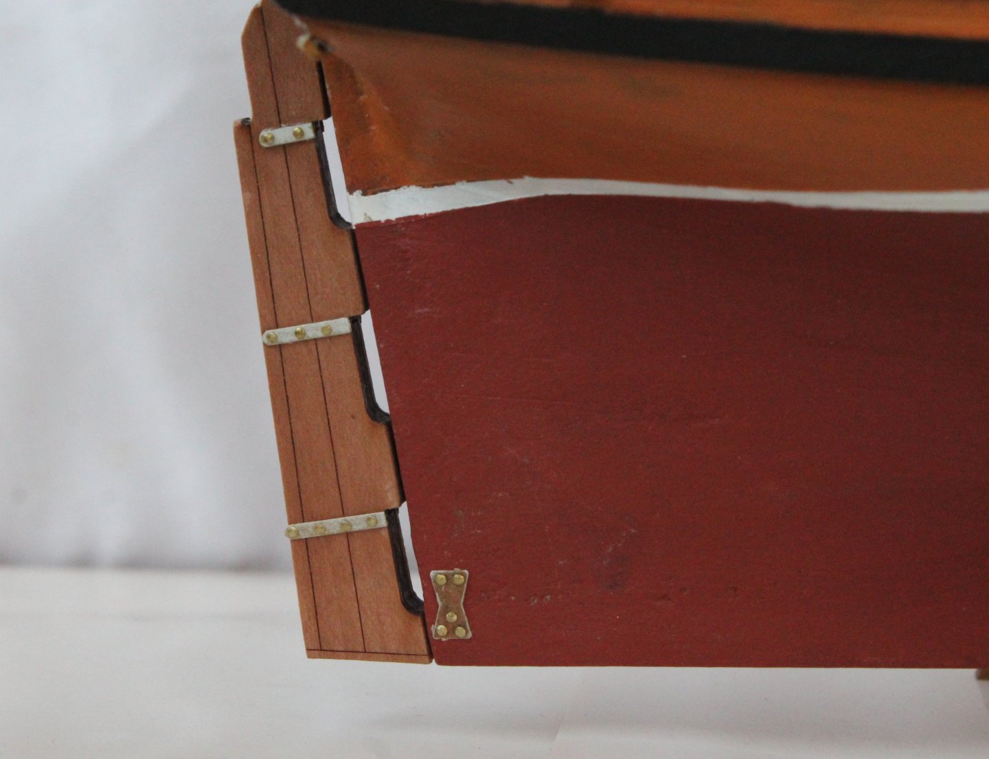
Build Log – Post 34 (09/01/26) Task 55 – Fitting The Rudder I had built the basic rudder assembly a few weeks ago. The first task, when fitting the rudder, was to add the rudder pintle strips along with shortened pins (simulated rivets) in the various pintle strip holes. The photo below shows a test fit of the rudder, noting the pintles had not been added at this point. Next I painted the rudder so it matched the hull colour scheme and then I drilled rudder so the pintles could be fitted. I did have to slightly enlarge the rudder opening to the deck area so the pintles could be inserted into the stern post. The final task was to add the pintle strips along with shortened pins to the hull. The paint on the hull strips is still wet in the photo below. I may need to add another coat or two. The hull pintle strips are incorrectly set as I mistakenly aligned then with the rudder pintle strips rather then the pintle part which is inserted in to the stern post. It is not an issue for this build but would be for someone knows how the should be aligned. I also have added the crown decorations between the gun ports


-
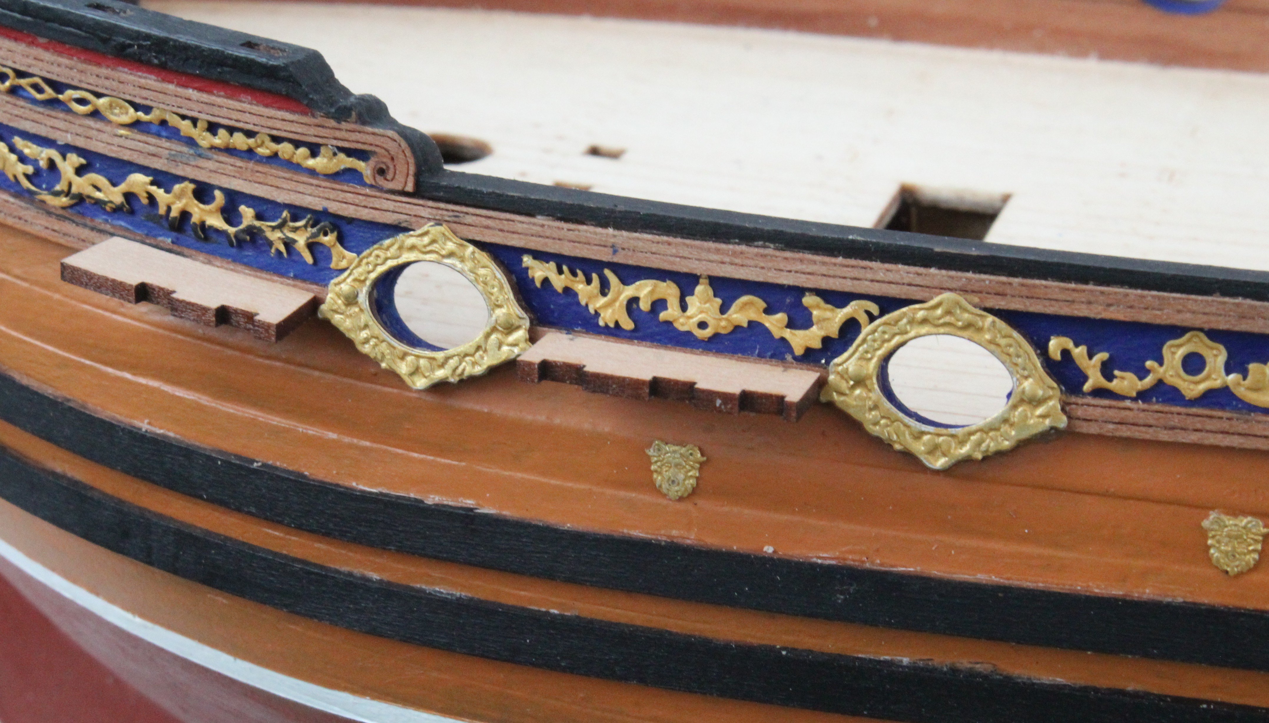
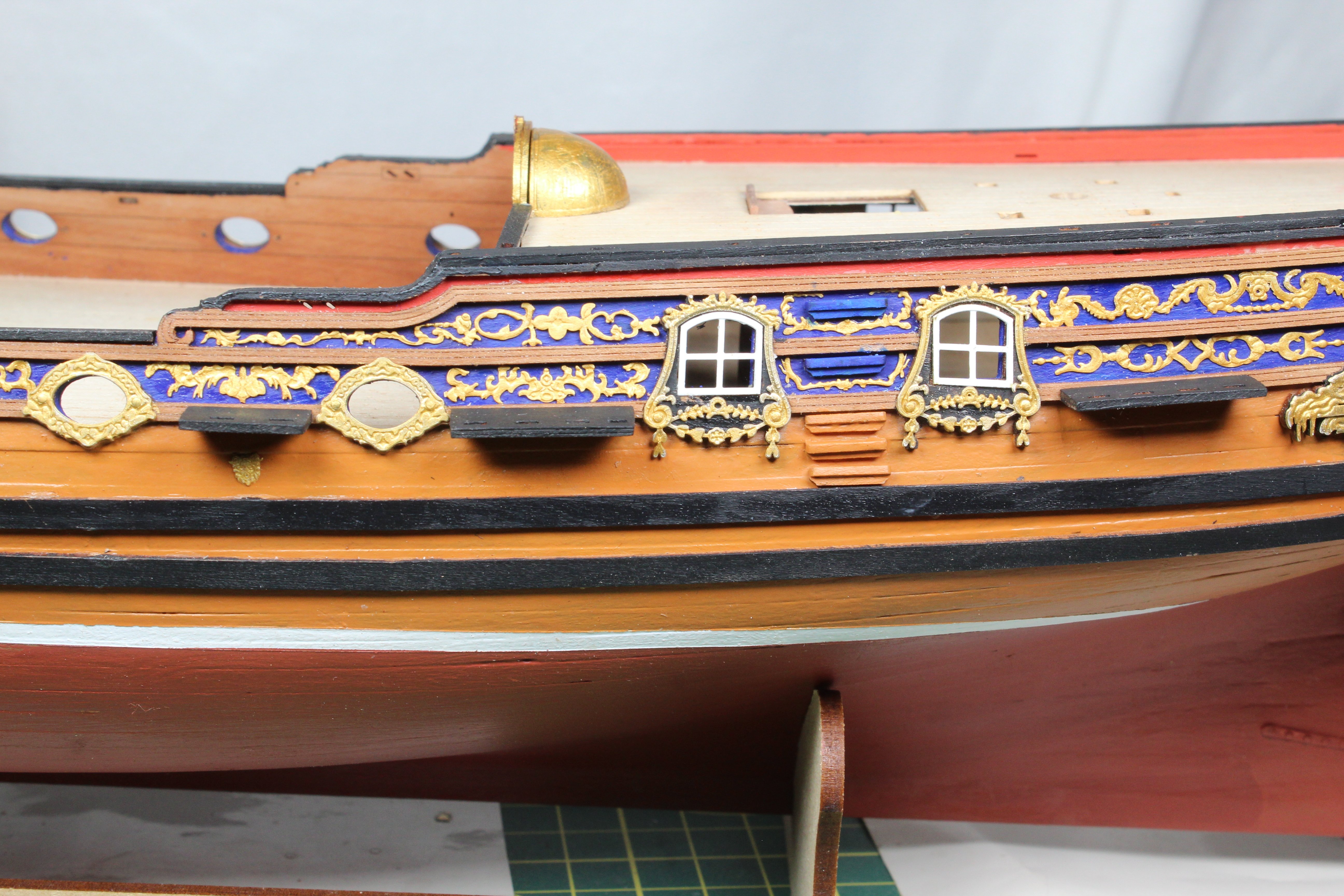
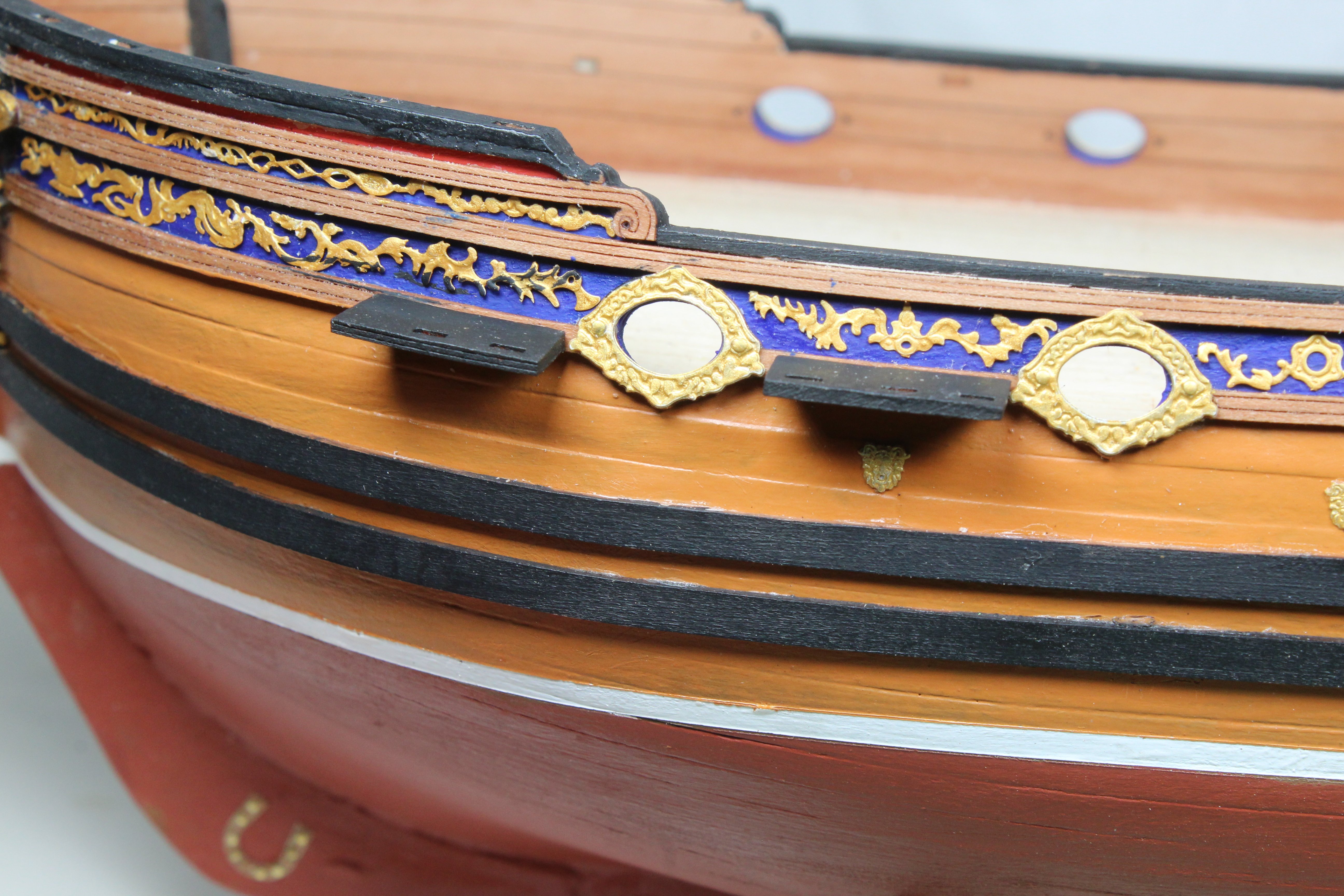
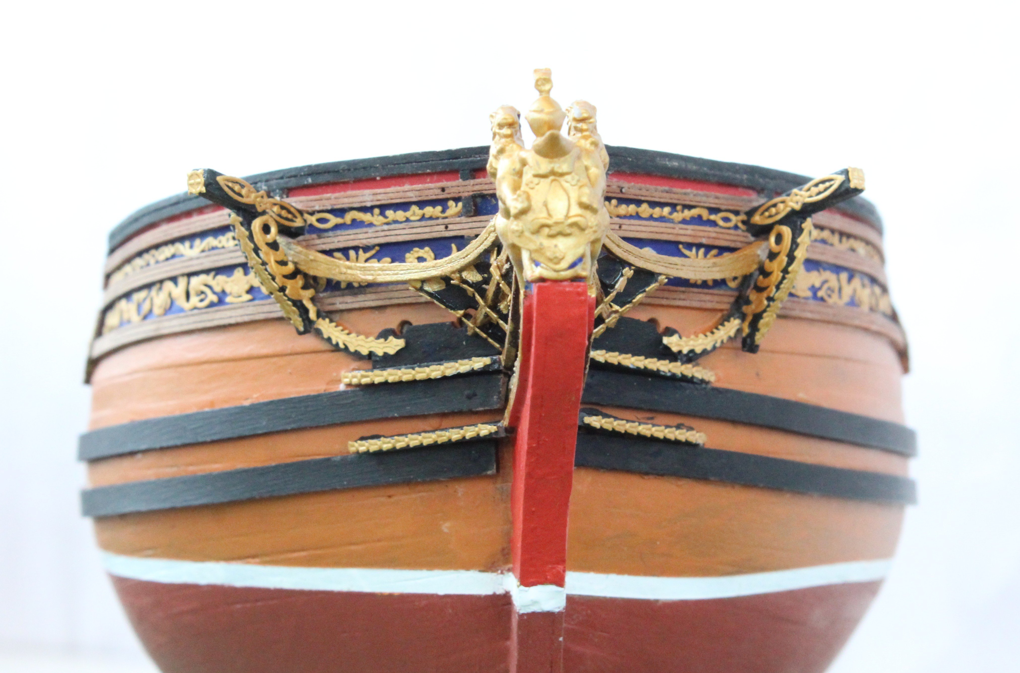
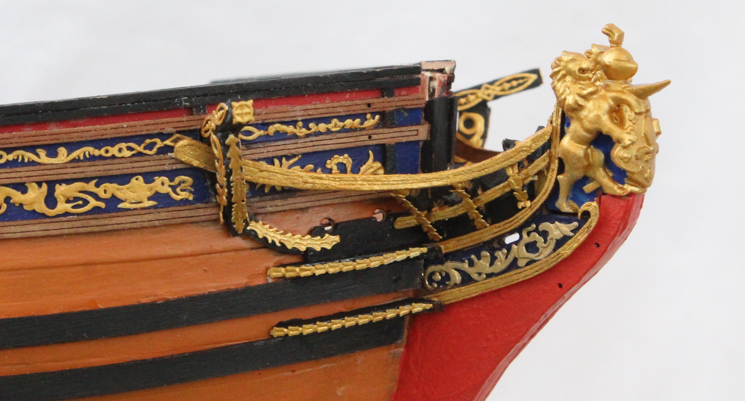
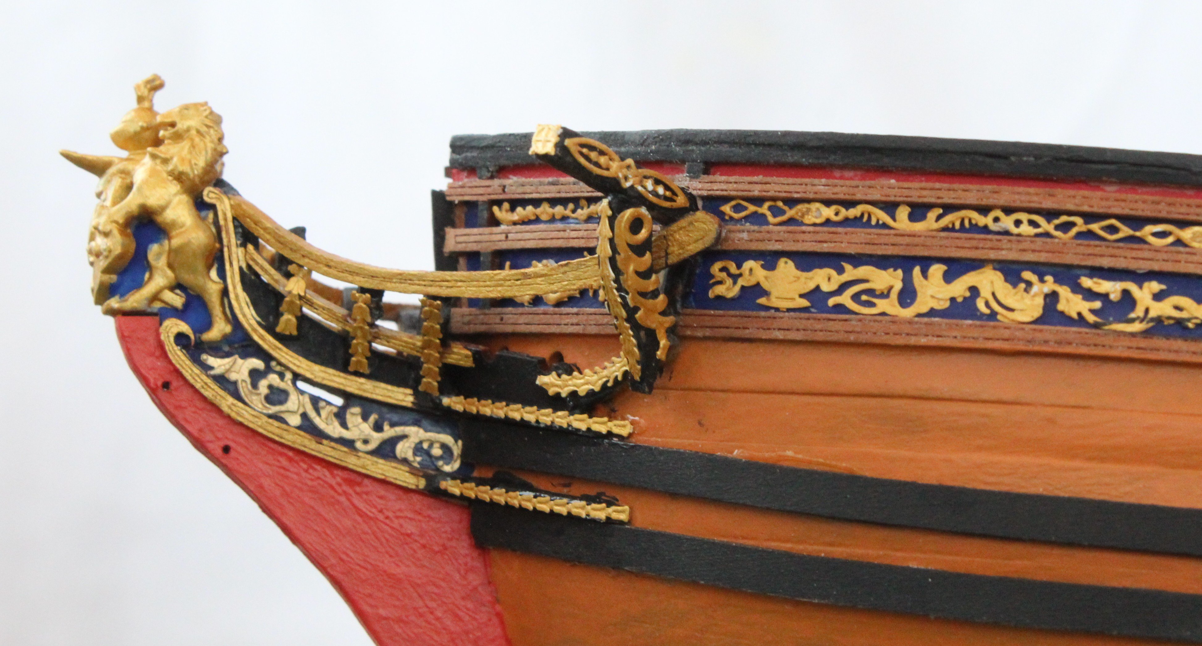
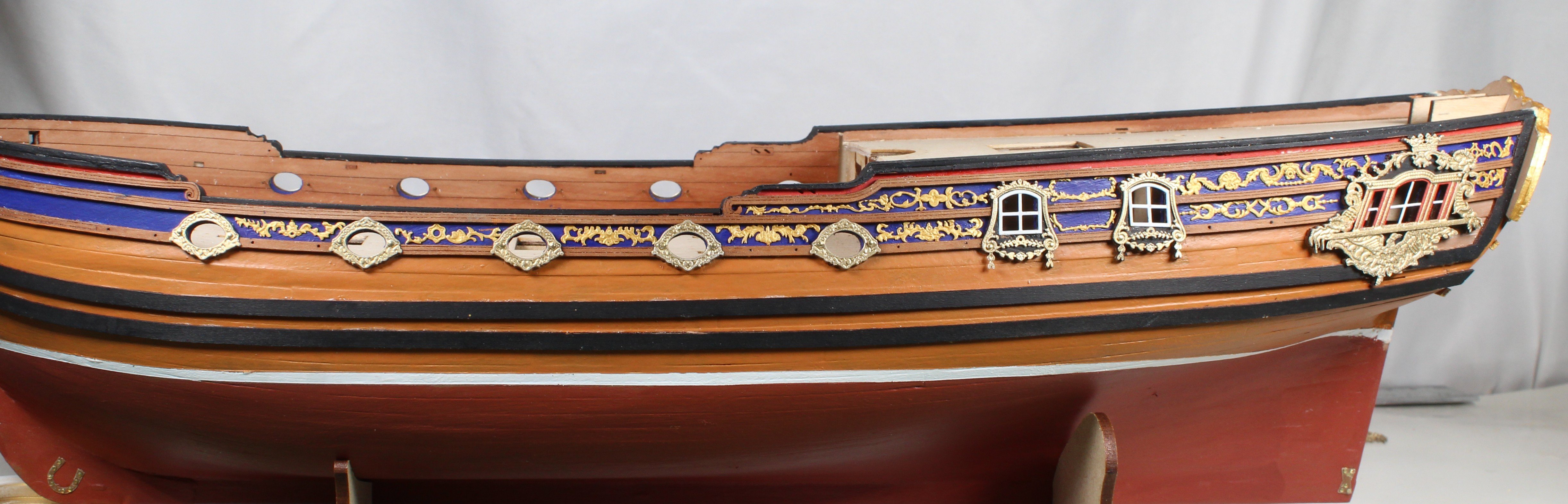
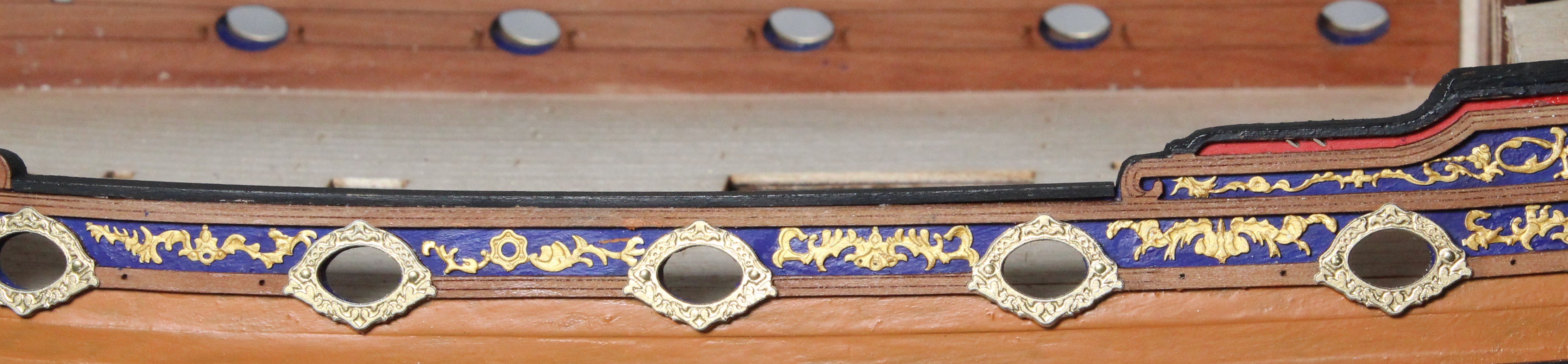
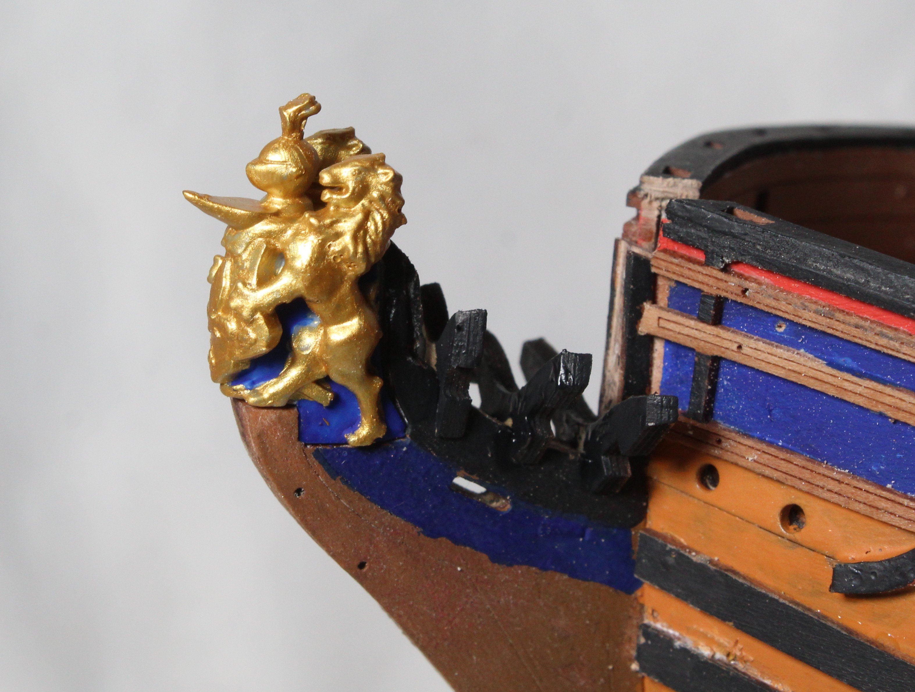
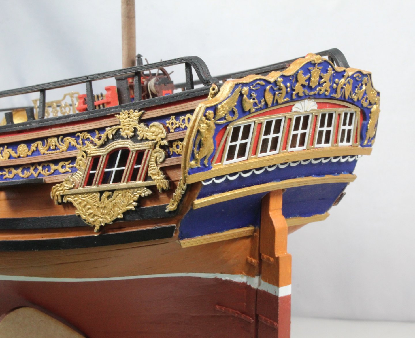
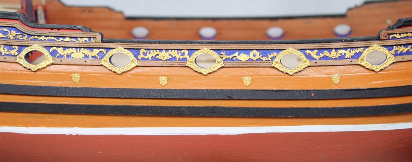
Build Log – Post 33 (07/01/26) Task 54 – Bow Rails, Catheads and Decorations Following on from my last post the remaining hull decorations were added successfully. Once that was done it was time to add all remaining details to the bow area. The various rails were added along with the catheads, hawse hole bolsters & brackets and figurehead. Once that was done the the various bow decorative patterns were added. I then decided to add a bit more colour to the stem post by painting the area below bow rail and above the water line red. Now that this work is complete, I can move on to adding the rudder. Photos The first two photos show the current build status, the Duchess is stating to look more regal, noting I do have some PE decorative crowns to add between the upper wale and gun ports Now a picture show the decorative bow area head on. The lower right-hand wale fit to the stem post is not very good Finally two photos showing the right and left bow area. I opted to paint the bow rails gold.


-
 Glenn-UK reacted to a post in a topic:
Chris Watton and Vanguard Models news and updates Volume 2
Glenn-UK reacted to a post in a topic:
Chris Watton and Vanguard Models news and updates Volume 2
-
Looks great and very neat work 👏
-
Glenn-UK reacted to a post in a topic:
HMS Surprise 1796 (prototype) by James H - Vanguard Models - 1:64
-
 Glenn-UK reacted to a post in a topic:
Chris Watton and Vanguard Models news and updates Volume 2
Glenn-UK reacted to a post in a topic:
Chris Watton and Vanguard Models news and updates Volume 2
-
Possibly, but I have no experience with shellac. My thoughts are you just need something which is clear when dry and will provide some level of adhesion when as it dries.
-
It works well, pe parts can be adjusted when first positioned and no nasty ca overspill issues
-
Build Log – Post 32 (29th Dec 2025) Task 53 – Hull Decorations I have now started to add the PE decorative patterns to the hull. I am coating each section of the hull with a thin coat of polyurethane varnish. I then wait for a few minutes to allow the varnish to get tacky before placing the PE pattern in place. Once the pattern has been positioned and being held in place by the varnish, I then apply a top coat of varnish. So far, this method seems to be working really well. Photos


-
Glenn-UK reacted to a post in a topic:
Chris Watton and Vanguard Models news and updates Volume 2
-
Glenn-UK reacted to a post in a topic:
HMS Surprise 1796 (prototype) by James H - Vanguard Models - 1:64
-
Glenn-UK reacted to a post in a topic:
HMS Surprise 1796 (prototype) by James H - Vanguard Models - 1:64
-
Glenn-UK reacted to a post in a topic:
HMS Surprise 1796 (prototype) by James H - Vanguard Models - 1:64
-
Glenn-UK reacted to a post in a topic:
HMS Surprise 1796 (prototype) by James H - Vanguard Models - 1:64
-
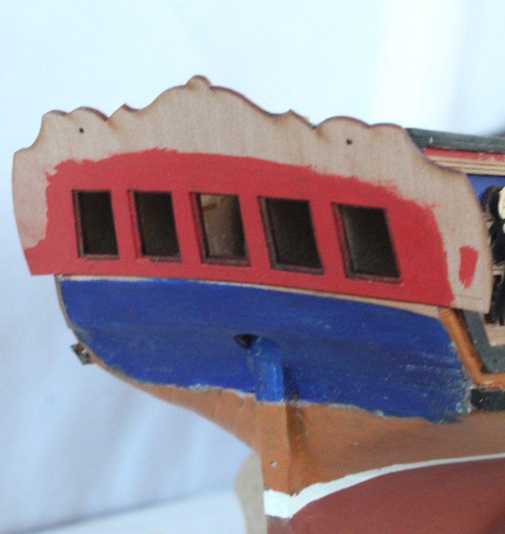
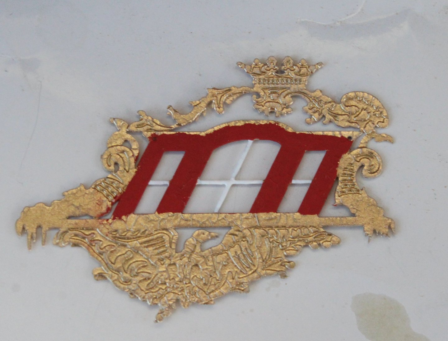
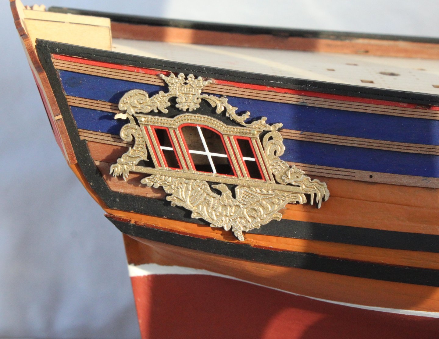
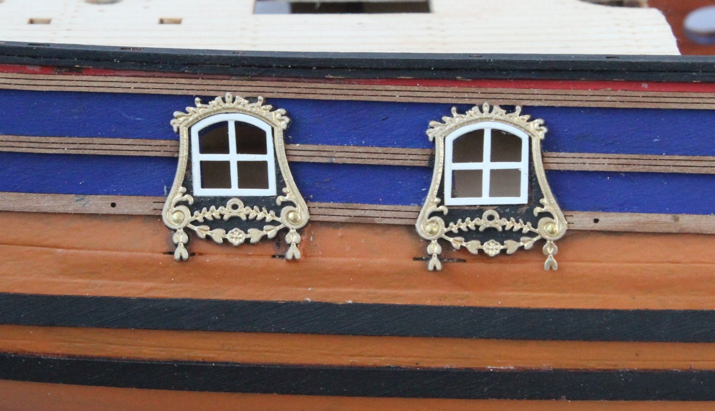
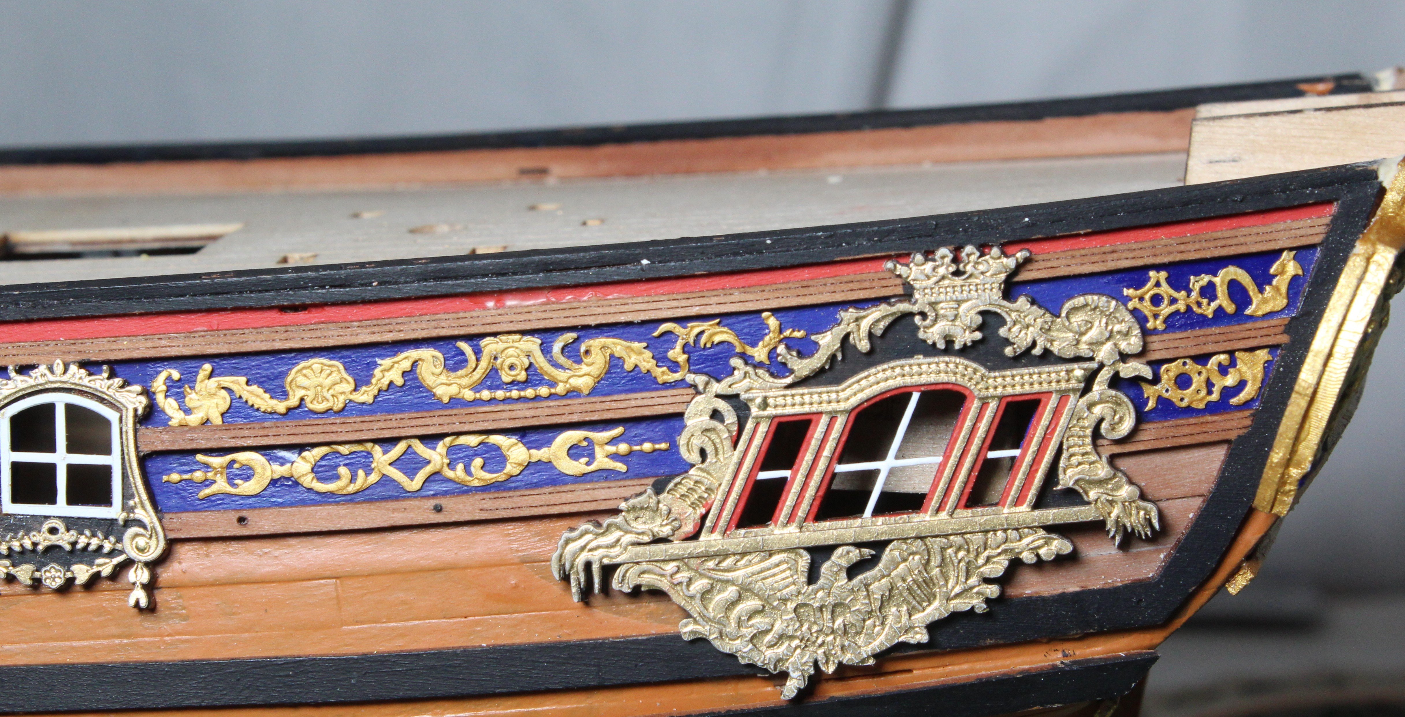
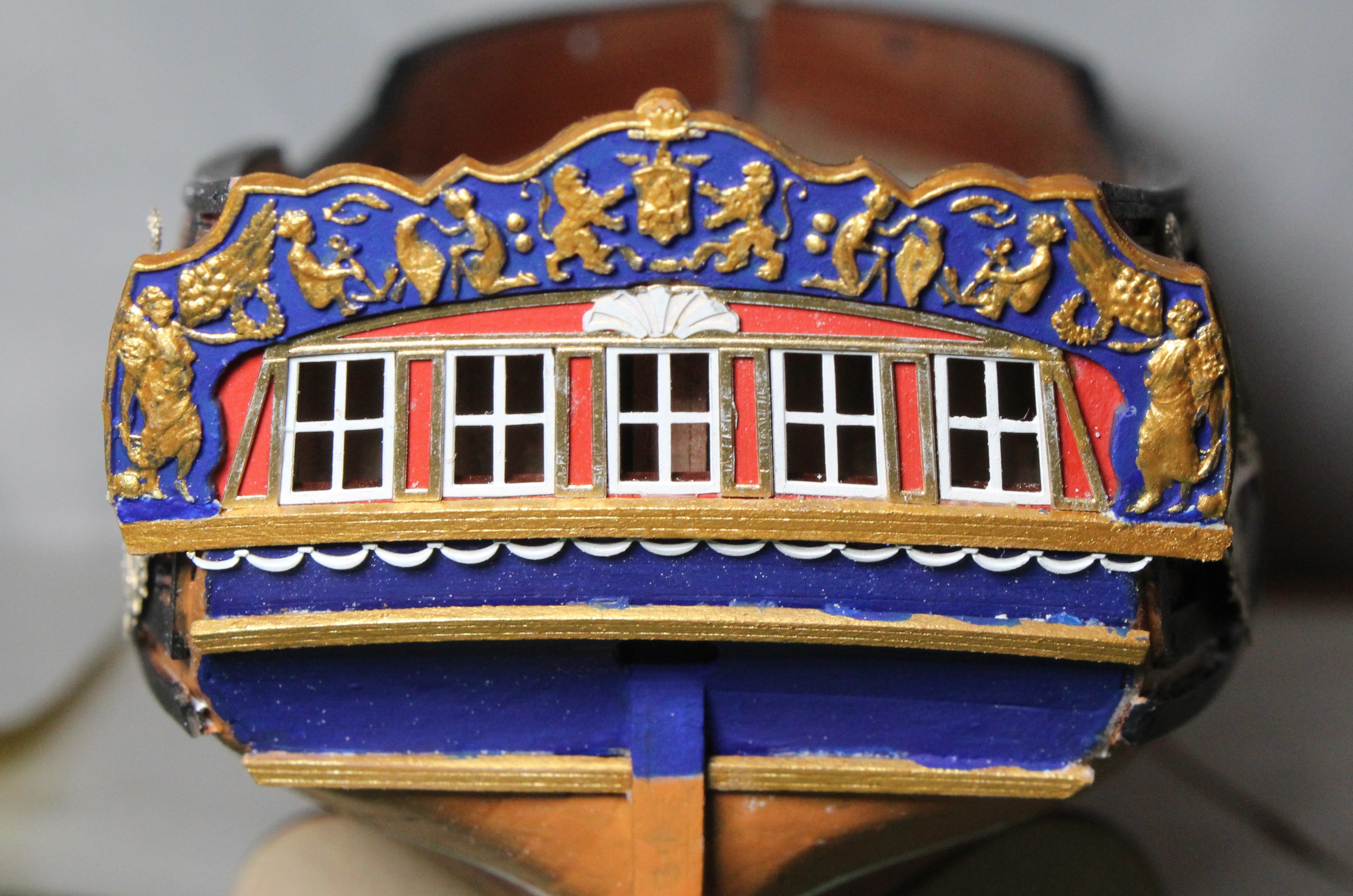
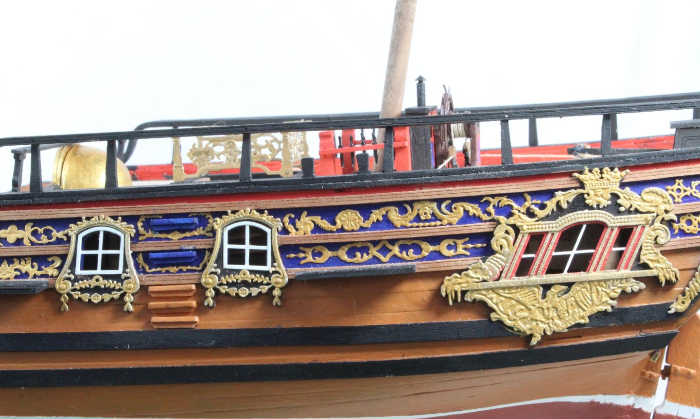
Build Log – Post 31 (24th Dec 2025) Task 51 – Upper Stern Counter Over the last few days I have been adding the various items to the upper stern counter. The first task was to add the white painted window frames. Next the window surround PE part was added. This had been painted gold with a white crest. The next item to fit was the 3D printed surround. The part was soaked in hot water for 15 seconds and then clamped to the stern counter for 1 minute so the bend could be added. The bent part was then dropped in cold water to cool off. The part was then painted imperial blue. Once the paint had dried the various raised shaped were painted gold. Once I was happy with the painted part it was added to the upper stern counter. Next I added the various rails, which had been painted gold. Finally, the final PE pattern, which had been painted white was glued beneath the upper rail. As can be seen in the photo below a little bit of paint touch up work is still required. Task 52 – Figurehead The figurehead has now been painted and test fitted.


-
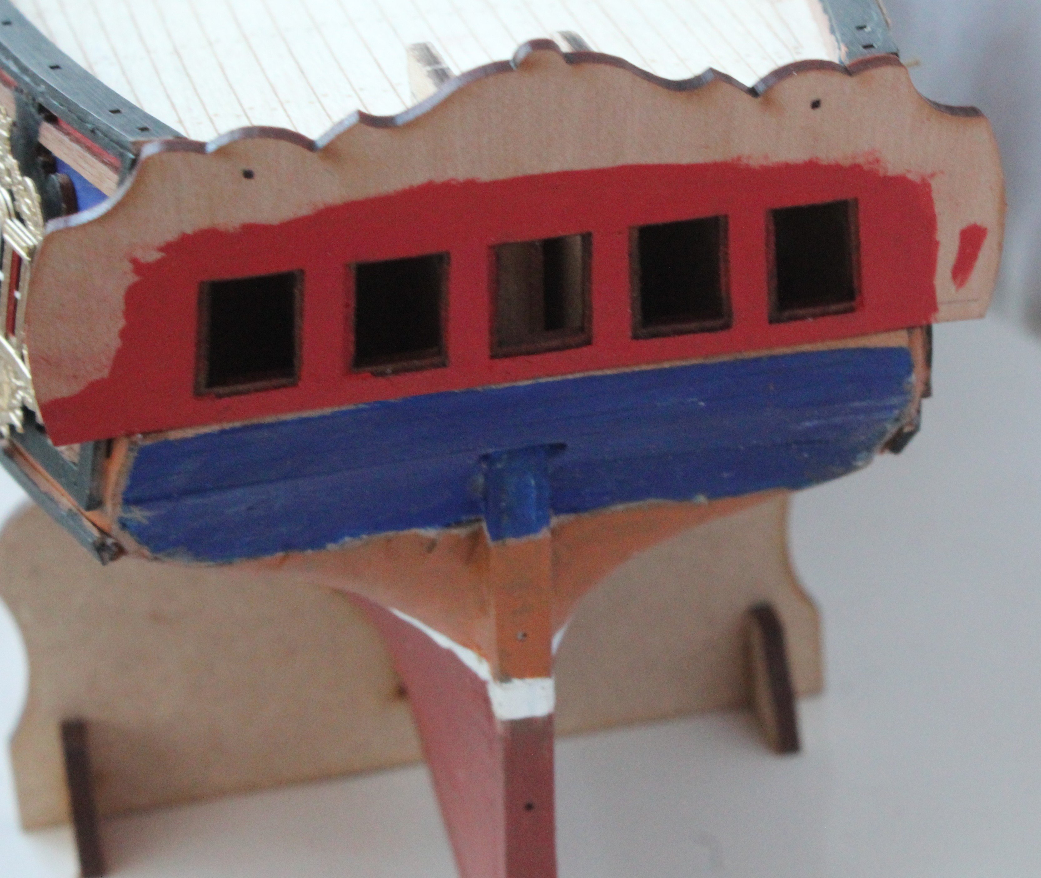
Build Log – Post 30 (19th Dec 2025) Task 50 – Upper Stern Counter Once the wales had been glued place I moved on to adding the upper stern counter pattern which was a relatively straightforward task. I did apply the red paint before this part was glued to place. Task 51 – Test Fitting Hull PE Patterns The main cabin decorative window comprises two PE parts. I had previously sprayed these parts with gold paint. The lower PE part window frame area then needed a red outline and window frames painted white. Using the pin holes to correctly align these two parts (not glued for the time being) a test fit was undertaken. I was happy with how this looks. I then glued the 4 off window frame PE parts to the side windows and test fitted the window surround patterns. Again, everything looks good. I will need to fill the gaps in the planking Next I decided to test fit the gun port surrounds. With these decorative patterns temporarily in place the build is starting to look like a royal ship fit for a duchess.