

tarbrush
-
Posts
439 -
Joined
-
Last visited
Reputation Activity
-

 tarbrush reacted to Jond in Gjoa 1872 by Jond - 1:48 scale - Amundson's Cutter
11 deck almost done and rigging no ongoing
I decided enough fiddling and completed my central pump gear and combined winch area. I tried to solder the small copper wires to the small brass square tube and went in circles. So, in the end I cheated and used Superglue. I tried using just magic marker, as we know brass and copper don’t like paint, that did not go well, so I eventually gave up and added paint. I call the effect a retiree’s distressed results. 🤫 It is not easy to photo so one can see all the parts.
1-3. these views show chains. The plan shows two chains, one to the pump and the second to the anchor winch. I do not believe they would have sailed so many miles with the chain rigged to the anchor. I may be wrong, but anyway I put it in as I assume my staging will be moored in the north country. 4-6 show three views of the central pump and winch assembly. There is a vertical arm from the big wheel that grabs the pump handle to move it. There is a wire frame outside it with the pump handle protruding though it so the arm is restricted to go only up and down as the bottom goes around the wheel. So far so good…I think I understand it. Now in all the photos, and thank you Harvey who sent me two, where does the chain or a gear engage the lower winch shaft. I had to make that up and just put it on the pump wheel. When I was building Bluenose a few years back and went to Lunenburg, Nova Scotia, I leaned in their museum about the various clutches needed so that one could engage different winches while raising different sails, wanting to raise the anchor, etc. With that logic, one could run the pump only or run the winches without the pump. The clutch would hold the shaft briefly as a gear would be slid sideways to engage, or in reverse to disengage. There was more stuff on a complete set up than in the photos and in my attempt to show it.
7 shows a little more overall and the anchor windlass chain inplace. 8 One more item is thanks to the prework of Harvey and others. I was able to shortcut the progress figuring out the tiller rigging. I had to remake the tiller as the first one just did not fit right. As to its rigging, I was on the right track because my sailboats had a tiller and we would lash it in a similar way when mooring or docking to hold the tiller amidships. Anyway, thanks for the insight I completed mine. 9 finally I scrapped the starboard side and it came out a little better…..Both sides no longer have red paint . I will have photos with the stain in place next time.
now we are heading into the rigging. I need to think about how I will stage things. Having read the diaries and chased images I am not sure. I think like me previous Bowdoin diorama I will show the crew about getting ready to sail away from Gjoa Haven. Some ice but water too. I also have to think about getting some crew. cheers
-
 tarbrush reacted to Lecrenb in St Roch by Lecrenb - 1:48 scale - RCMP Schooner rigged as schooner c. 1930/35
Happy New Year everyone!
Now that the relative riots are over, the turkey coma has passed, and the decorations are being put away for another year, it is time to get back to modelling!
St. Roch now has her mainmast installed!
The steps to finish the spars and main sail, and to assemble the mast, are the same as I carried out for the foremast, so I won't be repeating them here. The first picture is the mast assembled, held in my drill press vise that I brought to my model bench. Note the running rigging is pre-installed, and the cargo derrick is in place with my scratch built gooseneck.
Note also the chain and footropes on the main boom...
St. Roch originally had a gaff mainsail, but this was cut down and the gaff removed by captain Larsen after her maiden voyage. Presumably the smaller sail area helped her sailing characteristics, which were not very good. And here is the mast installed onto the ship...
The running rigging has been belayed to the pins at the mast foot. The back stays are installed. The main stay is installed to the spreader on the mast.
The crow's nest will be installed above the spreader, which keeps the stay out of the way of the nest. I made the Jacob's ladder and installed it between the top of the shrouds and the bottom of the nest.
As will be seen, crew climbed into the crow's nest through the bottom, not over the top.
The shrouds have yet to be made and installed.
In these next two pictures you can see the cargo derrick set up, with the crewman pushing his load of sacks to the side of the ship. The tackles used to swing the derrick are left slack on purpose, and the ends will be belayed to pins at the lower end of the main shrouds.
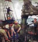
I normally do not include crewmen, since I am not very good at making them. However a friend on another forum and his 3d printer came to the rescue. I thought the open hold looked too sterile and the crewman would give scale to the model, so I used the following picture as inspiration to create this mini-diorama.
The photo was taken in 1928 during St. Roch's maiden voyage, as evidenced by her original small deckhouse and the note that she is unloading at Cambridge Bay.
It is interesting to note that there is no sailor manning the winch, the crewman appears to be working alone to get the cargo over the side and into, presumable, a shore boat...
This last picture shows my take on the scene...
Now all that remains are the main shrouds and some final details before St. Roch goes into her display case!
Thanks everyone for looking in and following along, and for your comments and support during my build!
Regards,
Bruce
-
tarbrush reacted to k-slak in Picket Boat #1 by k-slak - Model Shipways - 1:24
Hull is completed with a coat of semi gloss lacquer. And got to move onto building the boiler.
I opted for using brass bands instead of the paper for the boiler wraps. Wrapped them around a bottle about half the diameter then placed into a blackening solution.
The boiler top I had to think of it as a button and the shaping went great. I also finished it with a black lacquer - flat finish. Building the boiler ends was simple. Getting the wood to finish smooth with the acrylic paint was harder than anticipated especially on the stack but I got there eventually with a few rounds of filler, paint, and sanding.
The stack bands ended up being cardstock painted black as I couldn't get the bands of brass to glue and stay put. Overall the final look is good. When putting ont he boiler ends I drilled a small hole in each piece at center and put in a small pin this allowed me to get it centered and then just worry about things being oriented right. The pressure dial in my kit was a "cut from cardstock" situation but the cardstock was blue. So, I worked with my partner to find a gauge from one of his over kits that looked close to correct. It's not perfect but gets the idea.
One part I haven't done yet is the check valve that come out and goes into the "floor" in review of instructions it wasn't noted when this is to be done but it was definitely in the assembly picture. I'll likely come back to this next build session.
Here is the 90% finished Boiler with fire box and stack.
I'm hoping to do some good weathering on the pipes as the boat and system looking pristine doesn't seem right. If anyone has some ideas on how I'll take it. I have access to oils, acrylics and lacquers.
-
tarbrush reacted to Capt. Kelso in Kate Cory by Capt. Kelso (Quint) - Model Shipways - 3/16" scale - Whaling Brig
Have been finishing detail on the hull and deck. Temporarily set the masts to install the deadeyes, used the kit supplied chain plates which came out better than I expected. Almost finished with the Whaleboat Davits, Cranes and Bearer posts, a number of details still need to be added. Aligning the Davits and setting the Cranes to the correct height turned into a major task! Fortunately, I had finished the whaleboats in advance so I could use them as templates to set the height of the Davits and Cranes. Also, I needed to make sure there was enough clearance for the Davit Blocks. Seemingly endless adjustments! Oh, important point, the forward port davit for the waist whaleboat is on the outside of the bulwark.
Regarding the Davit Blocks. Actually, all the blocks. According to the Museum plans Kate used wooden and iron stropped blocks, iron stropped were used as Davit Blocks. OK, I may be a little anal about details at times. But I think they add a nice detail. I trashed all the kit supplied blocks and replaced them with "wood" blocks from Styrene and iron stropped from Bluejacket.
I'm pleased with the painting, still needs some touchup. I mixed my own enamel-based paints, scaled down.
-
tarbrush reacted to Fundysnapper in Benjamin W Latham by sideliner - FINISHED - Model Shipways - 1/4"=1' - kit ms2109
I love what you did to the transom. I am going to try the same thing.
-
tarbrush reacted to sideliner in Benjamin W Latham by sideliner - FINISHED - Model Shipways - 1/4"=1' - kit ms2109
Hello out there
As an afterthought I decided to take a shot at building the Latham Seine Boat. I don't believe I have seen anyone recently trying this. What I finished with is probably like no seine boat on earth. The instructions are limited and somewhat difficult to follow. Instructions say to cover hull former with water soaked( 24 hours) basswood 1/32x1/16 in. If I built again, I would use wider strips to keep glue from sticking to hull former. No way to clamp such fragile wood pcs, so had to use instant adhesive for entire model. I need training on applying this stuff. Unfortunately I accidentally erased my build log, but have included a few shots of finished boat. Trying to decide if I should mount it with the ship itself..
Getting ready to start on Xebec
-
tarbrush reacted to Fundysnapper in Benjamin W Latham by Fundysnapper - Model Shipways - 1:48
Started painting the deck and deck parts. Thought I would start there before attempting the hull. Still trying to figure out how to properly mark the waterline.
-
tarbrush reacted to palmerit in Benjamin W Latham by Fundysnapper - Model Shipways - 1:48
I'm not an expert - one thing I'd recommend: That looks like green Frog tape (or similar). For masking at the edge of painting a line like that, Tamiya tape (which is yellow in its thicker versions, white in its thinner) is significantly better (I've seen people test alternatives on YouTube and the difference is pretty striking) - it comes in a bunch of sizes (from really tiny to wide). It's kind of expensive (certainly compared to Frog tape) but you do not use much, especially if you just use it to mask lines being painted. Also, after you put the tape down, "burnish" the line by running the back of your fingernail or the back end of a paint brush along the line.
Another trick for painting a line: Imagine you are painting the top white and the bottom red and you already painted the top. After masking the line with (Tamiya) tape, paint white along the line and let it dry, so some white paint is where you'll be painting red and on the tape. Then paint the red. That one layer of white paint can really help keeping a fine line (along with using Tamiya tape and burnishing), limiting the bleed through under the tape.
I learned all those tricks here and the most recent line I marked off and painted was nearly perfect compared to the first couple of times I tried just using tape alone.
Depending on how OCD you are, you may still have some bleed through you'd need to touch up with a tiny paint brush, but doing these things can help keep the bulk of the line crisp.
-
tarbrush reacted to Jond in Gjoa 1872 by Jond - 1:48 scale - Amundson's Cutter
9 working on the deck furniture.
I am working away through the deck furnishings.
1. I counted ten main deck stationary items including the skylights, and here 8 of them are almost ready to glue down. 2 ,3,4. these three views show my experimental approach to make then main windless out of paper, a tiny wood dowel and plastic gears sanded down to size. The two deck brackets holding the shaft coming forward from the engine room. I switched to brass. 5 I am using the old thread trick to try to simulate iron rods for the forward skylight. I used pins on the aft cabin skylight. We’ll see if It works here. 6 here I have blackened the windless parts. the paint helps the paper become more solid looking. I found that black magic marker is better than paint however on both the paper [ second coating] and dowels. It does not thicken the dowel. I also used it on the brass clips. All is still loose here though I did make and glue down the engine room topside /skylight. I have no information, so I am following Harvey for what I assume is the engine cooling water return across the deck to be sure is stays above the water. I’ll talk more about the windless when I figure it and the two chains out. It is tiny at this scale. 7-9. here I show my rube Goldberg method of using my midi lathe to sand down to shape a mast that is longer than it. The railroad rail anvil is a family heirloom. I then stepped the rough mast just to take a look. It is shown to be absolutely plum in the drawings, so here we go. The last closer view shows the pumps going in and the bow sprit in place. There is still much to do here, and I am unsure of the mechanics of the rest of the deck workings. I a using the drawing section which is reasonable, and I will do my best but remain unsure as the photos are not complete and the system is not like our new England set up. It is fun to learn though
Cheers
-
tarbrush reacted to GioMun in Cutter Luisito by GioMun - 1/48 - A small cutter built to survive a shipwreck in southern seas
Ciao Shipmates!
Today i want to show the construction of the deck, it is already installed by now.
For start, i took a template from the model it self, then i made the layout of the deck furniture and other fittings, and then i took the template and i started to plank it.
I followed a pattern that i found in an old italian ship modeling book, it turned out very well, at least it dosen´t look like "parquet" 😉and it looks very real to me.
For the planking i used brazlilian pine, caulked with black glue (school grade), it leaves a very fine black line, very pleasent for the eye.
And for nailing, i made the simplest way, just a hole on the deck, and then i put a peg on it, after that, sanding, and that´s it. The nails and the waterways are made of rauli wood, (Nothofagus alpina), a patagonian wood, wich in this case, is a very apropiate wood to use, who knows if maybe Piedrabuna really used it on Luisito.
And now, pictures!
Well, i hope you like it.
See you soon!!
Greetings
Giorgio
-
tarbrush reacted to GioMun in Cutter Luisito by GioMun - 1/48 - A small cutter built to survive a shipwreck in southern seas
Ciao shipmates!
First of all, thank you for all the likes and comments. They are very important to me.
Thank you @Rik Thistle, i didn´t know about the book. I confirm to you that the book is about Luis Piedrabuena, the constructor of Luisito, i´m sure it must talk about in the book, it must be some more information about it, surely.
So, with these photos, i complete the chapter. I opened the hawseholes, and gave to the hull some polishing.
Brazilian pine is a rather soft wood, but hard enough to stand a good polishing and dye, unlike other types of pine wich aren´t suitable for that. Anyway some scratches were too deep to correct.
So, pics:
See you in next chapter. Black colored, and hull fittings.
Thank you for your interest.
Greetings.
Giorgio
-
tarbrush reacted to GioMun in Cutter Luisito by GioMun - 1/48 - A small cutter built to survive a shipwreck in southern seas
Hi shipmates!
So, i painted the hull completely black, i saw that in various models and i thought it would be a nice effect to give to the model.
I used shoe ink to give the color, and then i applied some coats of matte varnish, i liked the effect. I started the deck, but i will show that in the next time, i still don´t have good pictures.
So, i hope you like it. Ah, almost forgot, a carpenter showed up, one of the Commander´s helpers.
Chapter 4. Colouring the hull and fittings
Next, i will show the deck plancking, still under construction.
I hope you like it.
See you soon.
Giorgio
-
tarbrush reacted to GioMun in Cutter Luisito by GioMun - 1/48 - A small cutter built to survive a shipwreck in southern seas
Ciao Shipmates!
So, i finally finished the planking. It´s still raw, still have to do some sanding, polishing, etc., but you can see the idea how it goes.
I decided to do not nail it, since the hull it´s going to be dyed in black, and anything of it would be visible. I will let that to the deck planking.
I´m not very happy with the result, there are some mistakes wich i wish they weren´t there, but they are! Some of them i just found them with the macro of the camera. They are barely visible for the naked eye. So, a lot to do better next time.
I hope you like it and thank you for your comments of course.
Also, i made the rudder and modified the head of the stempost, in order to make the space for the bowsprit.
Photos:
As i said, a lot to be sanded, polsihed and corrected!
I will post some picutres or the finished plank after this operations are done, and then.... Chapter 4!
Thank you for your interest.
Greetings
Giorgio
-
tarbrush reacted to GioMun in Cutter Luisito by GioMun - 1/48 - A small cutter built to survive a shipwreck in southern seas
Hi shipmates!
I started the planking. First i marked 4 rows, then divided them in to 3, in order to achieve the best number of planks. This done following, not precisley, the David Antscherl practicum.
As for the plans of the Luisito, i know that the plans we are using (i say we for all the modelers that are building it), are from of course a survey done, i mean a ¨as built¨ set of plans.
Of course Piedrabuena didn´t have any drawings available with him. He later said that he managed to remember the lines from his studies. This set of plans is signed by an architect who happens to be a shipmodeler too, maybe he maneged to draw this set after that survey. You can search in the web Arq. Carlos Rando Ferrer. He is an argentinian architect, teacher and shipmodeler.
The bullwarks are planked too, using 3 rows of planks in each side.
This wood i´m using is very easy to bend, so no big difficulties so far. For caulking i´m using black glue (school grade), once sanded down it leaves a fine line between planks. So, lets go to the pictures.
Chapter 3 - Planking, calulking and nailing.
Thank you all for all the likes, the comments, and the views.
See you next time!!
Greetings.
Giorgio
-
tarbrush reacted to GioMun in Cutter Luisito by GioMun - 1/48 - A small cutter built to survive a shipwreck in southern seas
Hello. I´d like to share my new project.
It is about a little cutter, wich was built after a wreack of another bigger ship, in order to go back to civilization. A model and a surviving tale.
Chapter 1. Introduction and History
Luis Piedrabuena (August 24, 1833 – August 10, 1883) was an Argentine sailor whose actions in southern Argentina consolidated national sovereignty at a time when these lands were virtually uninhabited and lacked state protection. His biographers consider him one of Patagonia's greatest heroes. Piedrabuena rose to the rank of Naval Lieutenant Colonel, equivalent to Commander. Today, he is commonly known as Commander.
When his brig, Espora sank in March 1873 on Año Nuevo Island, and the possibility of salvaging the ship was ruled out, Luis Piedra Buena, its commander and owner, decided to build a boat to escape the difficult situation he and the crew members of the sunken vessel found themselves in.
It is still unclear whether the cutter was armed with timbers from the Espora or with the trees on the island, which was very close to the wreck, an ideal forest for using in the construction of the boat. The original type of Wood used, was ¨lenga¨, (Nocthofagus pumilio). The work was carried out by him and one or two crew members; the others were ill or simply uncooperative, which makes this feat even more impressive, not only because of his effort, but also because it was not based on any plans. He used his memory and knowledge of what was teached to him by Capt. William Horton Smiley, a whaler who was a friend of his father, and gave him the chance of learning sailing skills, and ship construction, and also, remembered the forms of chilean launches tipycal of the Patagonia, wich are very similar to Luisito.
In just over two months of work, he built the cutter Luisito, amidst storms and southerly winds. He named the cutter "Luisito" in honor of his deceased first son, who bore that name. Once the ship was completed, he left Isla de los Estados and arrived a few days later in Punta Arenas (actual Chile).
Once the cutter was launched and ready, it set sail to Punta Arenas, arriving after 11 days of sailing in May. After a stay of several months, amidst the southern winter, it sailed from the Isla de los Estados, and during that voyage, in August, it rescued the six shipwrecked people from the English brig Eagle, who were half-dead from hunger and cold on a rock. It led the rescued shipwrecked people to Punta Arenas and rescued them again, this time those from the German ship Dr. Hansen, whom it brought back to Punta Arenas.
Piedra Buena continued to travel along the southern coast with the Luisito.
In 1875, Piedra Buena had to travel to Buenos Aires, where Congressman Dr. Félix Frías needed his knowledge of the south to apply it to the border issues with Chile. In order to raise the necessary funds for the voyage, Piedra Buena decided to sell the Luisito, a sale that would be finalized in early 1876.
Ship Information
Length: 10.66 m
Draft: 1.52 m
Average Draft: 1.40 m
Displacement: 14 tons
Full deck, with a hatch at the Stern, and a storage locker at the bow.
One mast, with a trapezoidal sail, jib, and staysail.
Tiller.
Wales around the hull.
Chapter 2. Early stages of the model
So, the model is built in 1/48 scale, POB, in brazilian pine mostly, (araucaria angustifolia), and some parts in rauli (nothofagus Alpina).
I had the structure laser cut, for more precision, a practice that i will incorporate in my models from now on.
The model construction started with the assambly of the structure, and the bulding of a slipway, as usual.
After stat stage, i made some fillig between stations, in order to give the model more strength and a surface to do the planking and nailing.
Next, installed the keel, sternpost and stem, and of course set up the wales. First i had to build the transom, in order to correctly install the wales.
So that is all by now. See you in chapter 3, with planking.
Greetings.
Giorgio
-
tarbrush reacted to GioMun in Cutter Luisito by GioMun - 1/48 - A small cutter built to survive a shipwreck in southern seas
Ciao Shipmates!!
Sorry for the silence these last months. I being busy with family, work, as usual. But i managed to make my way throw the workshop and could start Chapter 5.
So, i made hull fittings and deck furniture, and in this moment i´m working on last fittings in order to finish the hull.
Chapter 5 - Hull fittings & deck funrniture
First of all, i post some pictures of the general view. Some pictures were taken before varnish and others after, so that´s why the color difference.
As you can see, the mast is already built, still need some finishing, and fittings, still not installed.
Luisito had a main entrance hatch for the crew at the stern, and a cargo hatch at the center, no description at all about how they were built, so i took the liberty to shape it my self. As for the missing eyebolt, well, we are all modelers, so you know what happened, it fell to the ground at the moment of getting it to its place. 🤭 I will have to build some new ones. And as you can see in some pictures, there was a small hatch at the bow, wich i added in the moment of the photos were taken.
You can see the different tones of brazilian pine, you can find some very different patterns as the one for the deck, and the one for the deck furniture. A very good wood to work with. I strongly recomend it if you can find it.
Some views of the metal fittings and the rudder hinges wich are very separated from the sternpost, i don´t know why, and i don´t know if that affected the navigation capabilities of the ship, but that is the way they are in the plans. I am now discovering that the scarph joint on the starboard side is not as tight as it seems in naked eye! 🙄Will correct.
The macro of the camera makes everything a little more "goofy" than it seems with the naked eye.
Finally, i post some pictures of detailes, hope you like them.
So, that is all for now. Next i hope to post pictures of the completed hull, with all the fittings and ready for rigging.
See you soon!!
Arrivederci.
-
tarbrush reacted to Ronald-V in USF Confederacy 1778 By KennyH78 - Model Shipways - 1:64
Just picked this one out of Chuck's log, you can see the run of the planks quite nice here.
There are more pics from different angles also 👍
-
-
tarbrush reacted to Bryan Woods in Fischkutter by Bryan Woods - Laser Creation World - 1:35
This I believe is a mid 1900 German fishing boat. Skills of their trade were passed down through generations. This kit is a part of a diorama that I don’t intend to build. Hopefully I can furnish it with proper equipment. I would like to try the weathered look.
The frames and spine are plywood. The planking seems to be .5 mm basswood, the was laser cut. It has 3d printed tires, drums, fuel containers and small crates. The captains wheel, rudder and light are also printed.
-
tarbrush reacted to Bryan Woods in Fischkutter by Bryan Woods - Laser Creation World - 1:35
Besides working on the planking I laid the planks on the deck. I decided to use a smaller width than what was provided with the kit. That’s some of it on the right.
I’m about halfway completed on the planking.
The way I chose to plank , it can’t be the best way. But it only uses second grade math. Of course, it’s not done yet. I just measure the longest bulkhead and divide it by 4, (my plank width ). Take that number, that I round to whole and divide it into the measurement of the first bulkhead at the bow. And that’s what I cut the taper at the bow end. I’ve ended the taper starting. #5 but the last few I went to #6. At the bottom, about the third plank, ( when it went past the first bulkhead and landed on the bow stem) I started tapering them also. It’s probably just this hull but it has stayed pretty consistent. There will be 4 or 5 planks with both ends pointy.
-
tarbrush reacted to Admiral Rick in Picket Boat #1 by RVB (Rick) - FINISHED - Model Shipways - Scale 1/24
I’m up Suns Up Anchor’s Up and setting sail on another day of boiler and steam engine work. Without the engine and no wind and occasionally getting caught in the irons (with a very demanding 20 year old granddaughter) work must be done. Turning my attention to finishing the steam boiler!
-
tarbrush reacted to Jond in Gjoa 1872 by Jond - 1:48 scale - Amundson's Cutter
3b painting prep and firs paint
This update shows steps to get the lower hull ready and painted so I can removed if from the jig.
views 7-8 show results of glazing putty repairs and marking of the waterline. the hull is wet as I just damp rubbed it to get off all the dust.
views 9-11 show my low tech means to build the gudgeons in brass and the plates and bolt heads using mylar fishing line
views 12-13 show taping out the black section above the water line and afyer painting it.
views 14-15 show taping out to allow rattle can spray of heritage red for the bottom and "backside".
I mentioned earlier that I am trying to build this model without buying new stuff. As anyone knows, 12 years into retirement, our home collection of parts, wood etc. is ridiculous. The problem came up when I started to spray red with a can that has sat for more than a year, it wasn't pretty. We'll see in the next post how all came out.
cheers
-
tarbrush reacted to Cathead in Gjoa 1872 by Jond - 1:48 scale - Amundson's Cutter
This looks like a great project. I'm a big fan of Amundsen as an explorer and leader, and will enjoy watching this story take shape.
-
tarbrush reacted to Nick 843 in HM Armed Cutter Sherbourne 1763 by Nick 843 - Vanguard Models - 1:64
I'm cooking with gas now on second planking. The system of edge bending and then dabbing some water on a section of plank and working that section with my travel iron, then going on to the next section, is working really well for me. I only have two planks glued on at this point, one each side, but two more just about ready. I'm doing two at a time to match them up either side. My steps (just what works for me):
Nip the two planks to match the angle for the rabbet. Sand a bit on the rabbet end as needed. Mark one for the taper cut; double/line up with the other plank in the Dremel vice (metal jaws without the rubber covers). Then it's easy to plane both planks at the same time. The mini plane works great for this. Bevel the plank edges. Edge-bend the planks to the outer bulwark contour. I clamp the end of the plank (first pic in my earlier post) and then just wet the plank in sections and work along with the mini iron. Then, one plank at a time, dab a bit of water on the section of plank nearest the rabbet, but without getting water on the rabbet insert, get it just wet but not dripping so as not to drip water on other planks/model. Insert the rabbet end and lay the plank in place. Work the wetted section with the mini iron. The mini travel iron is working great, for the edge bending but also for this; I'm finding it heats up almost instantly versus the soldering-iron -type plank bender, and is way more manoeuverable and precise. It only takes a few seconds to work the particular section. Repeat 8 as needed. Continue along the plank in other sections to get the bow curve, same as 8-9. So far anyway, I don't need to work the middle section of the plank as the edge bending has done the job there. Work the stern section of the plank to bend and twist to fit. Here I'm using steam from a kettle and bending with pliers. After a final fit check and any adjustment/repeat, it's ready to glue. I'll have to adjust once I get further down towards the keel, but I think it will be much the same, with just garboard and it's neighbours a bit different.
Nick
-
tarbrush reacted to Redshadowrider in US Brig Syren by Redshadowrider - Model Shipways - Scale 1:64 - First wooden ship build
Gammoning & Bumpkins….
Despite the continuing heat, we had a few days where I could get some work done on the Syren. I have been able to complete the bumpkins, including the mounting brackets. I tried the copper strips folded over, but I ended up using some card stock. The gammoning turned out to be easier than I expected, but ‘easier’ is very relative. To complete the gammoning I did make a small hook out of a RC control rod so that feeding the line would be easier.