HOLIDAY DONATION DRIVE - SUPPORT MSW - DO YOUR PART TO KEEP THIS GREAT FORUM GOING!
×


RMC
-
Posts
933 -
Joined
-
Last visited
Content Type
Profiles
Forums
Gallery
Events
Everything posted by RMC
-
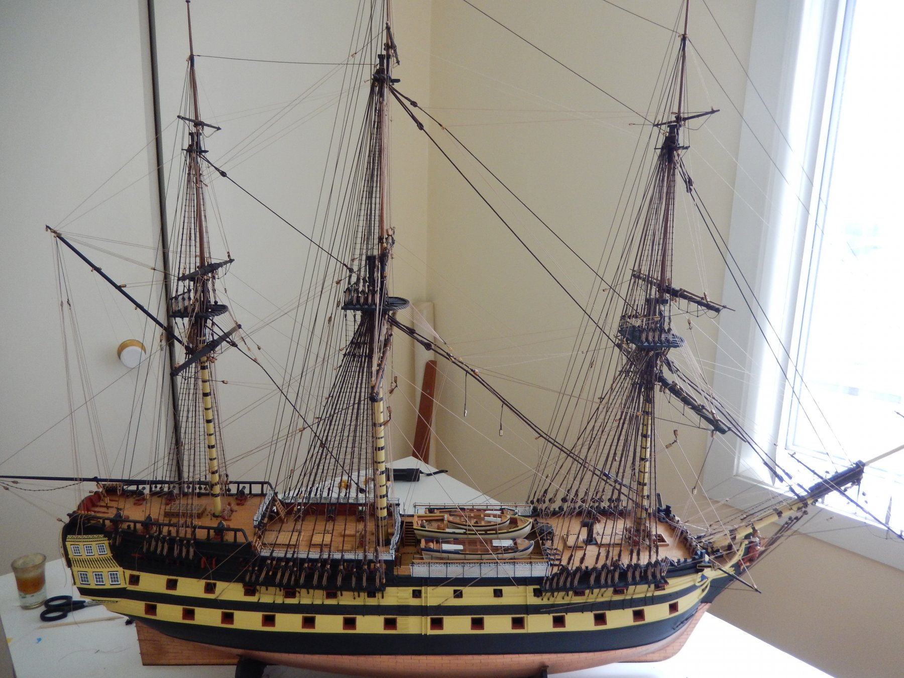
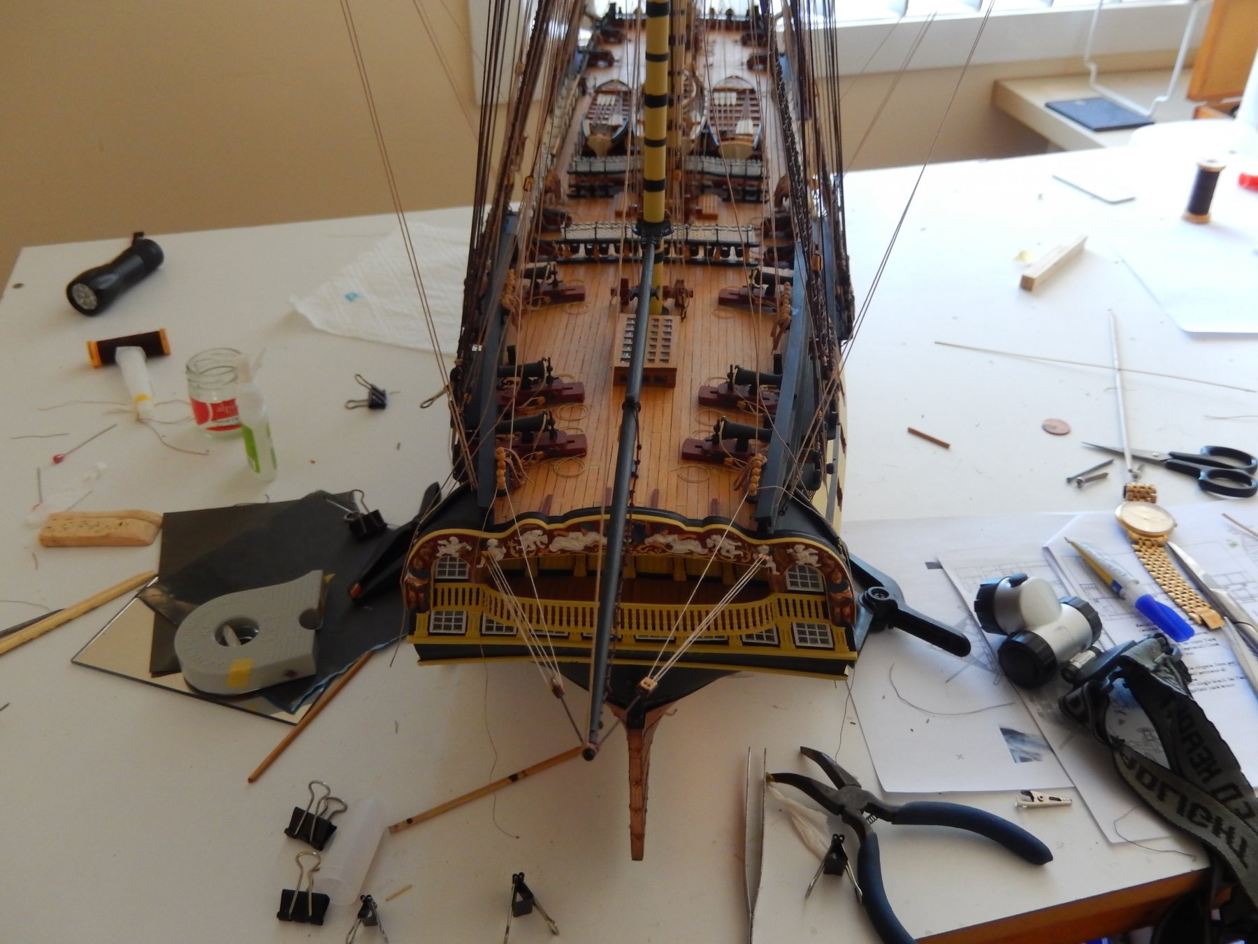
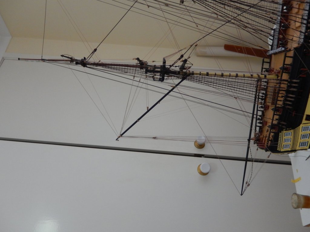
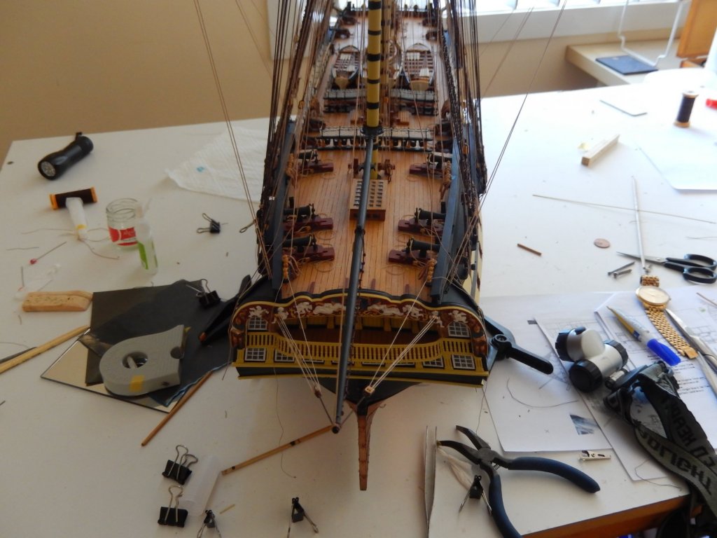
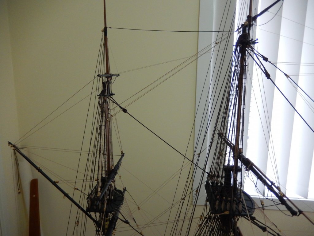
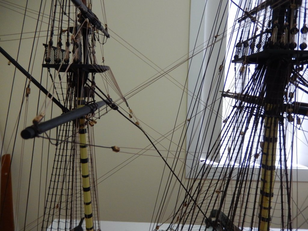
The rigging is finally complete but for tidying up and mounting some rope coils. There is one omission: the rigging of the ensign halliard. There is no indication on the plan to show where the lower block should be rigged and the positioning is not obvious. Recourse to Petersson (aka the bible) drew a blank and the internet ditto. So this Vanguard shall remain flagless unless someone has a suggestion. I am now hoping to restrict any future knot-tying to shoe lace,s and thinking about what, if anything, I will do next - suggestions are again welcome. Here is what it all looks like now. The lights are to be installed, gunport lids put on and the rudder mounted. Once all of that is done over the next 2 or 3 weeks, I then have figure out what to do with the damn thing. The photo following is a product of my losing battle with Windows10/Nikon. I rotated the picture in the Nikon software to portrait and here is the result. Ah ha! The Nikon software apparently doesn't talk to the windows10 software. Rotating the photo in Widows10 did the trick.


-
Sorry Peter. I completely misunderstood what you had in mind. I have looked closely through the windows of my model (including shining quite a powerful light through them). You really can't see anything of interest. (I did paint the triangular pieces black.) I have not used the perspex for the windows that was supplied in the kit, but rather a MicroMark product (mentioned somewhere in my log) which I think looks far better, though not as translucent as the perspex. That may make a slight difference to what you can see, but really I don't think it's worth the trouble. All the Best Bob
-
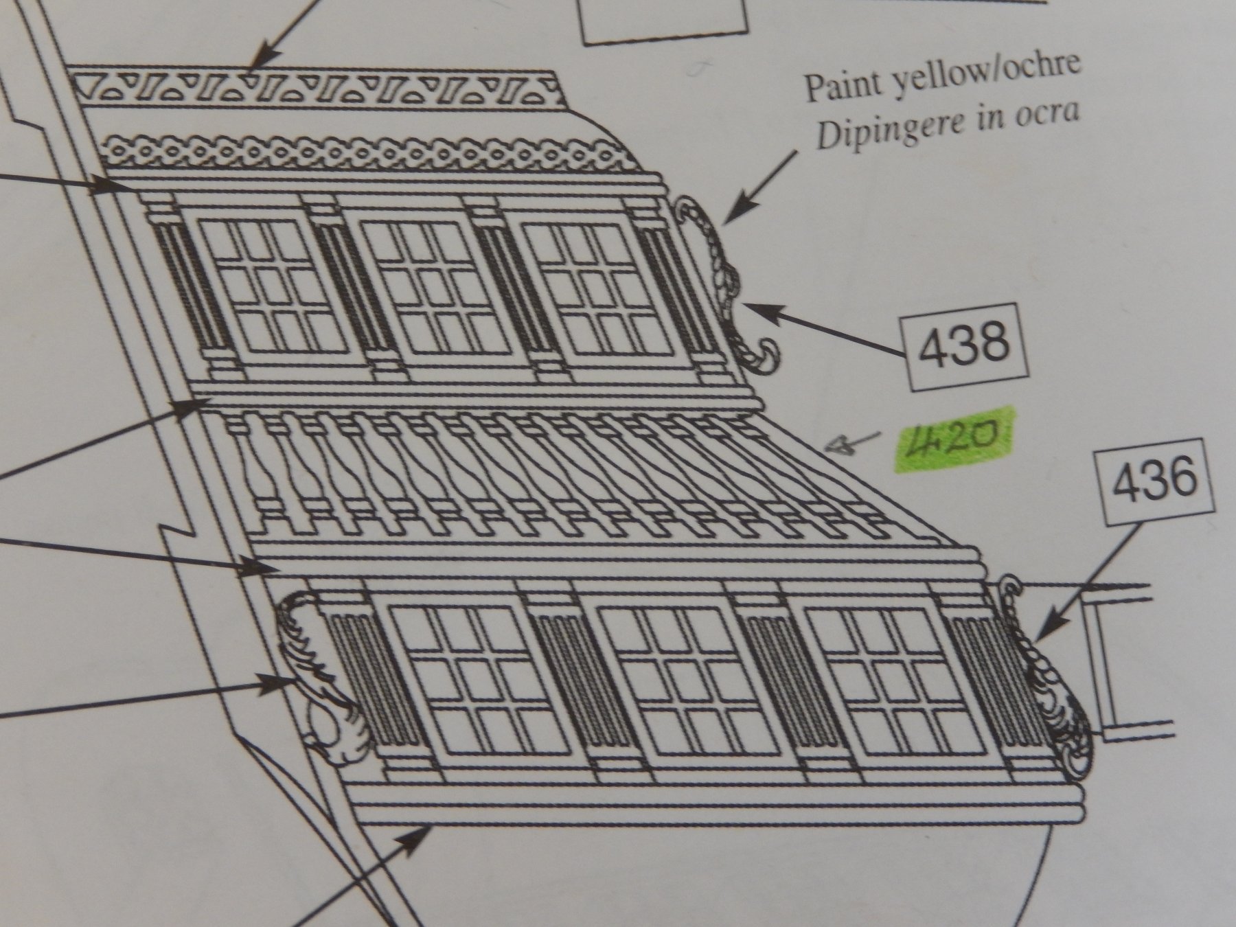
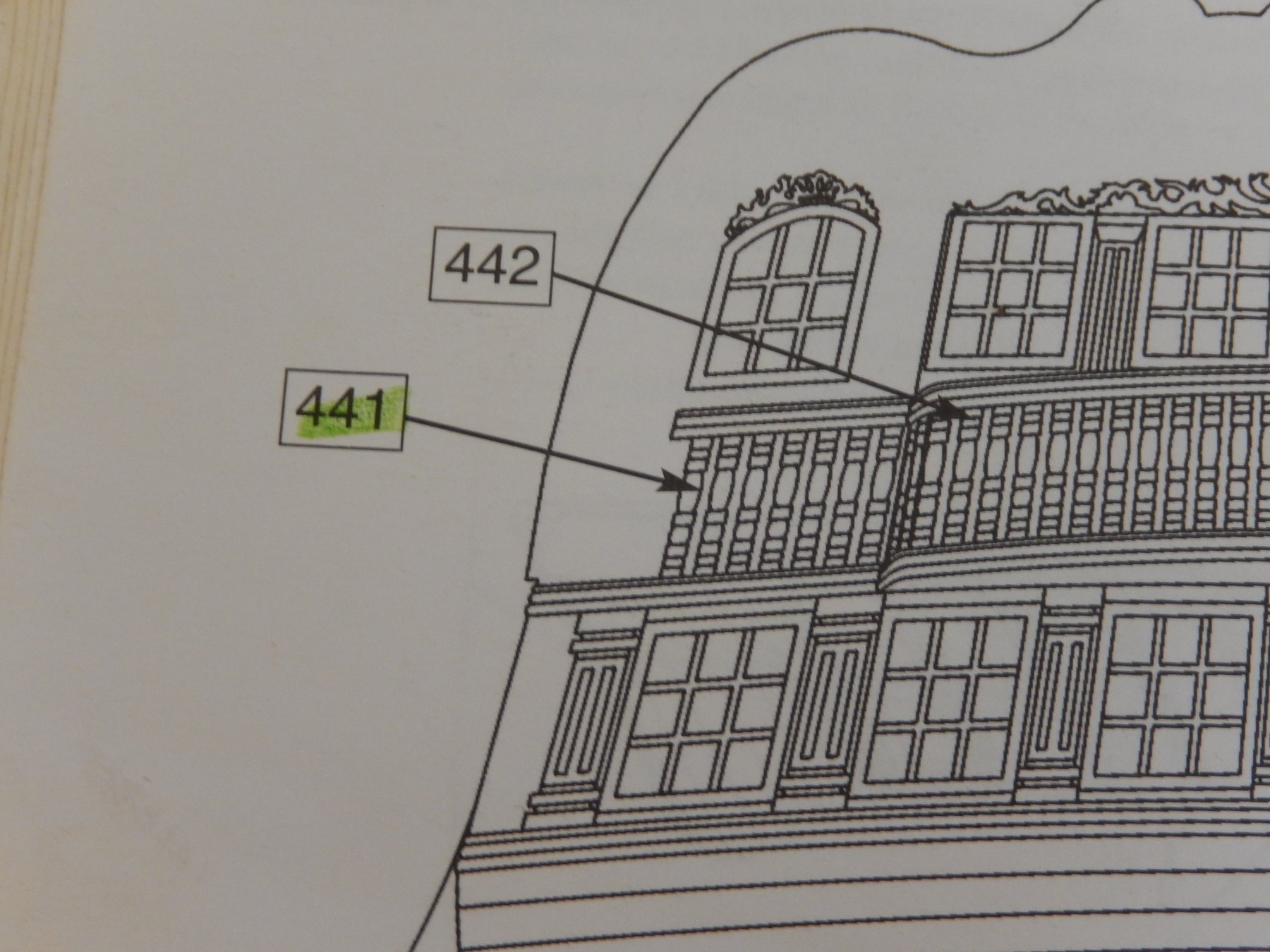
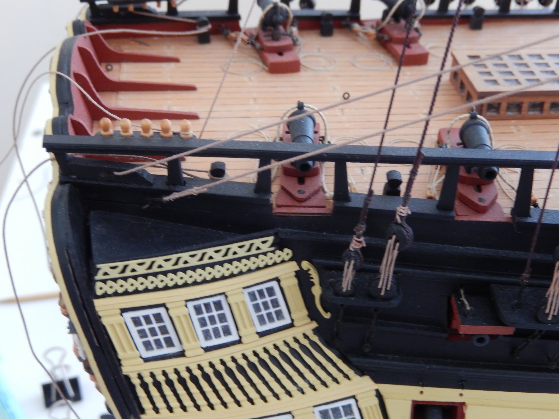
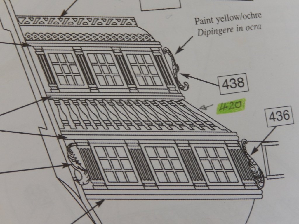
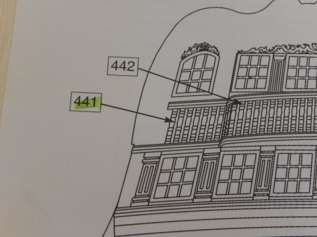
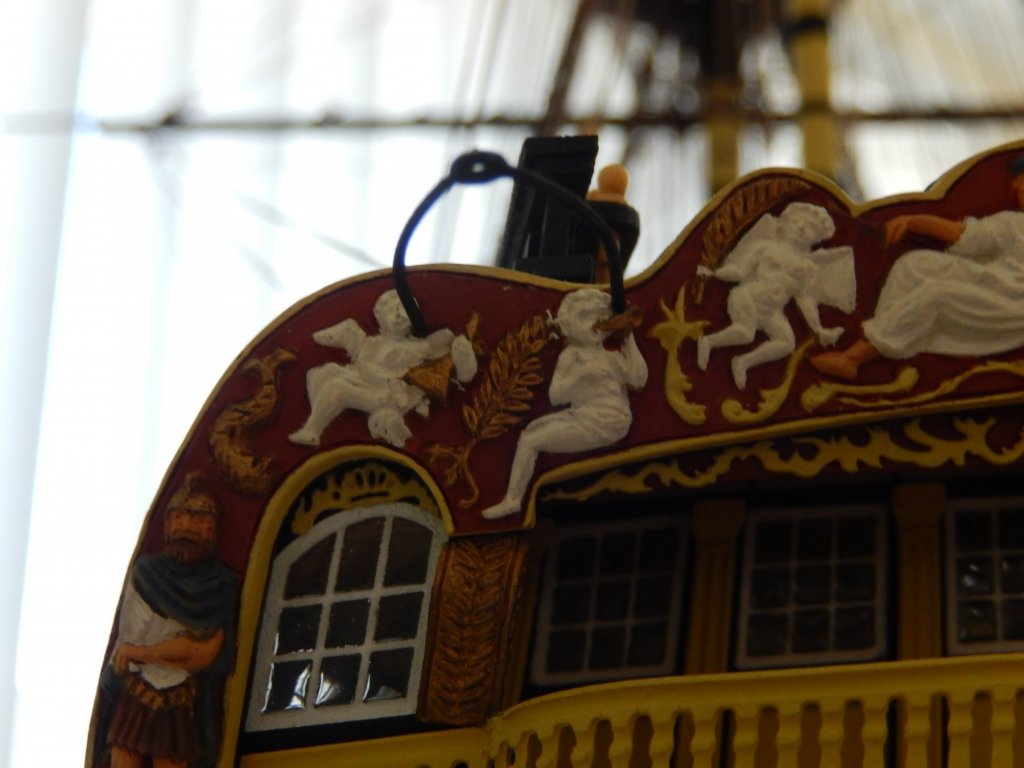
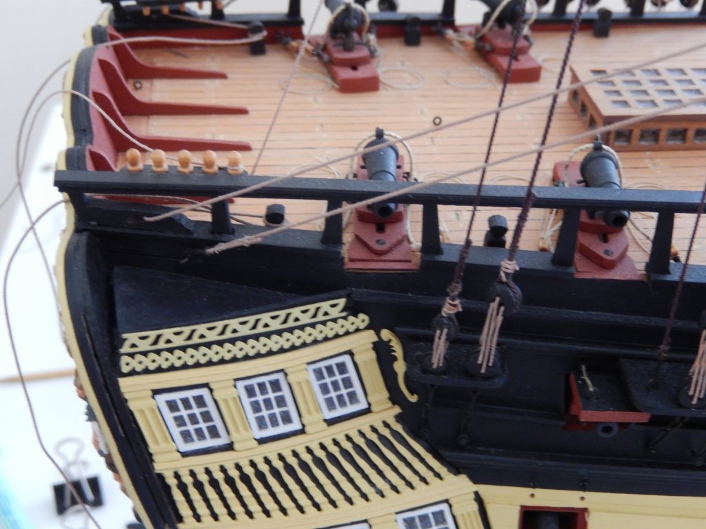
Hi Peter I'm not certain that I follow you, but here goes. I presume you are talking about the part labelled 420 in the photo below (the quarter gallery balustrade), and perhaps the decorative piece labelled 441 in the following photo. You wish to bring these parts slightly away from the timber backing to provide the appearance of depth to the galleries. At 1:72 scale I don't think what I understand you propose would make much difference. There is already a tiny gap between the pillars and the black backing giving some some appearance of depth as the pillars are not stuck on the the backing. If you wish to accentuate the gap I would stick a very thin strip of copper along the top and bottom of part 420 (and 441?) which would make the gap a little bigger, thus giving a greater appearance of depth. Hope this helps. Bob
-
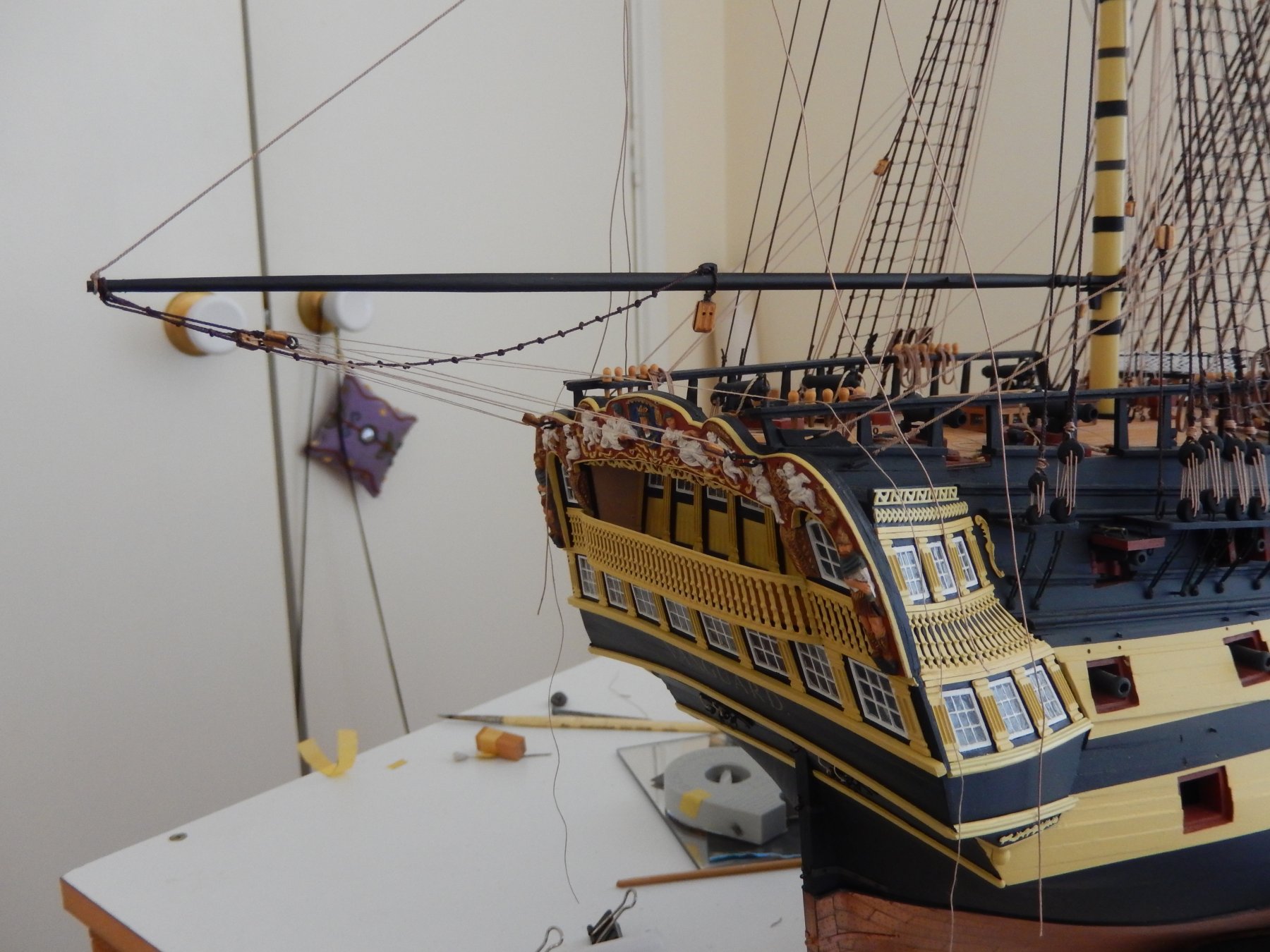
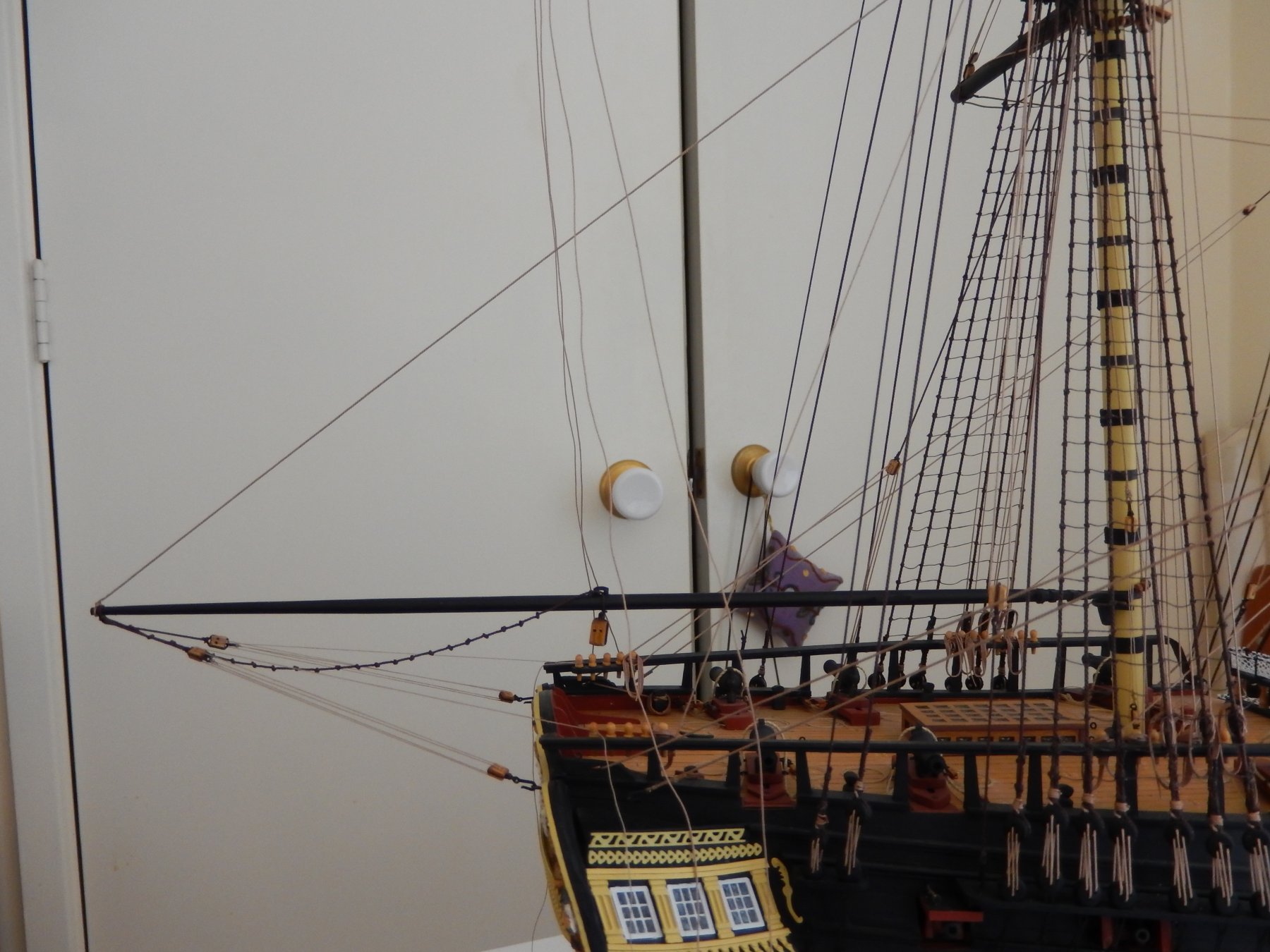
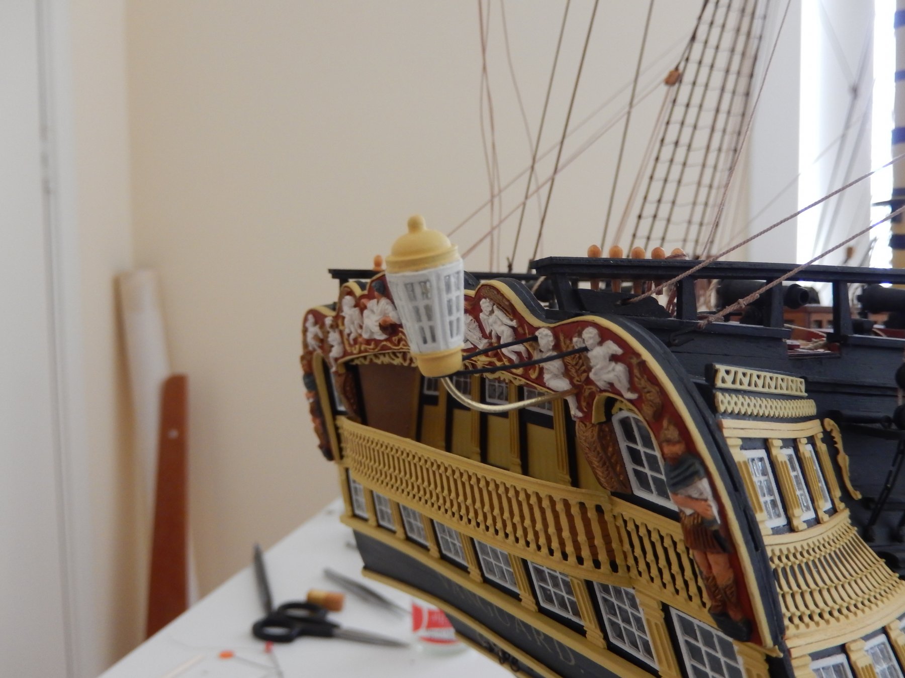
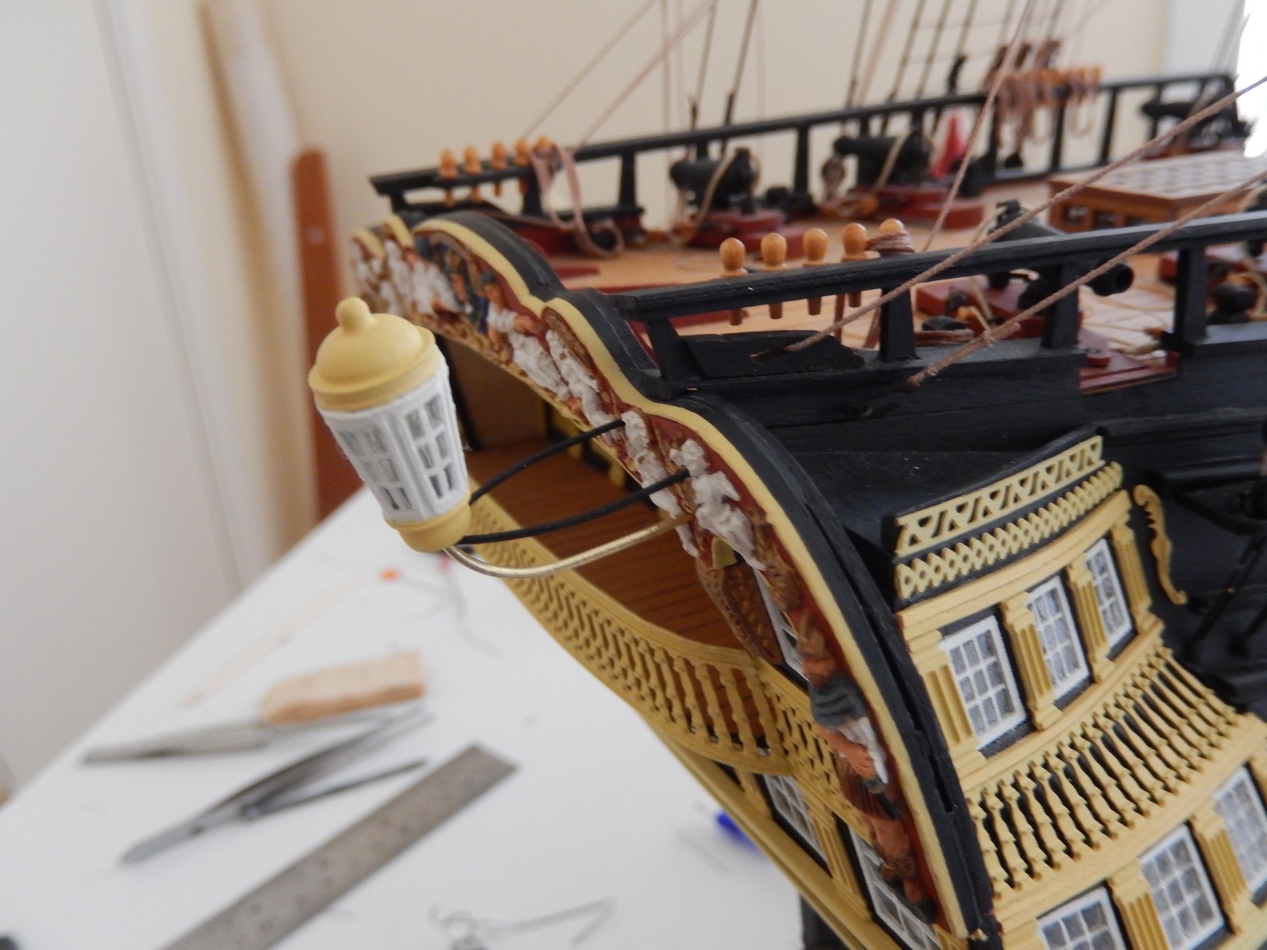
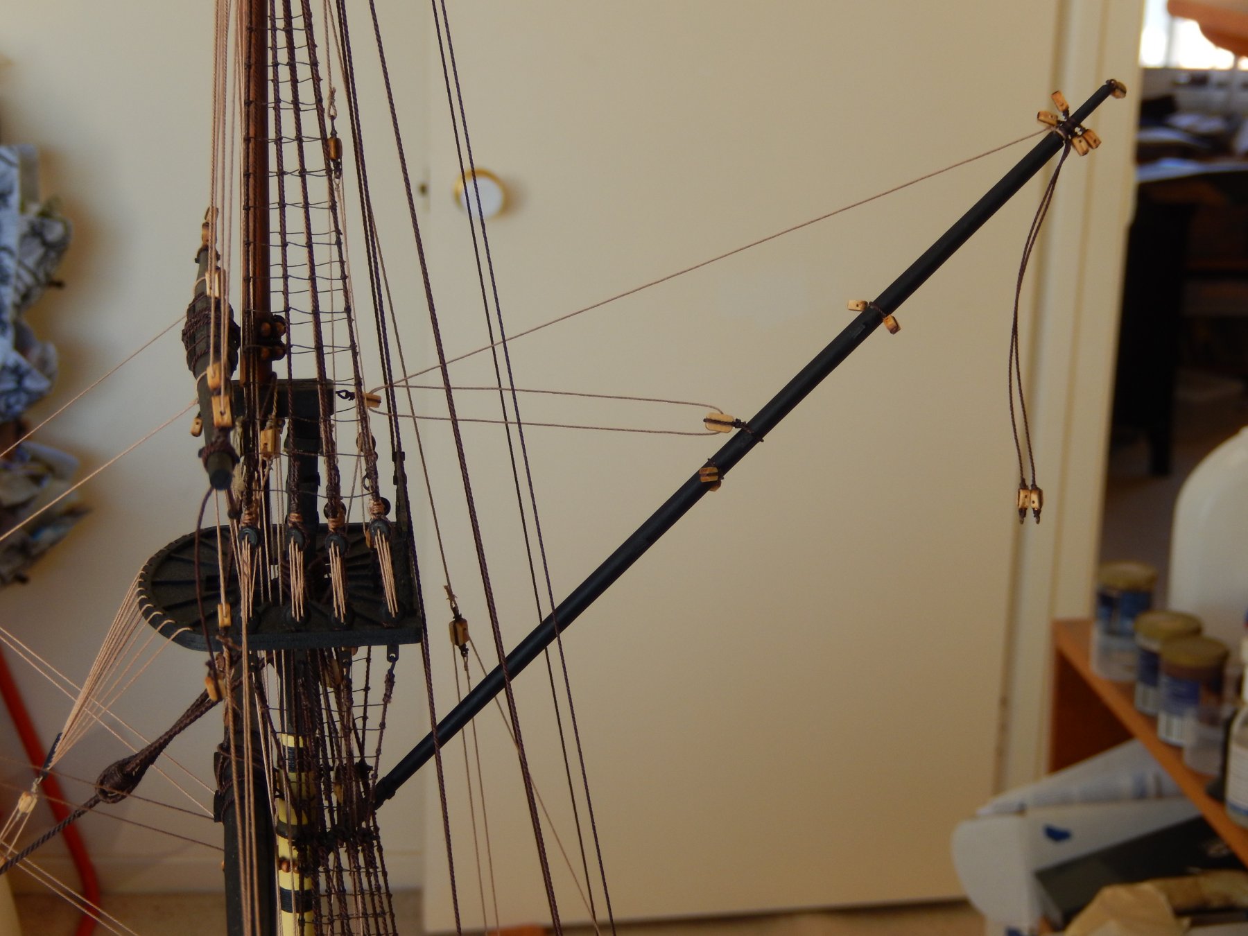
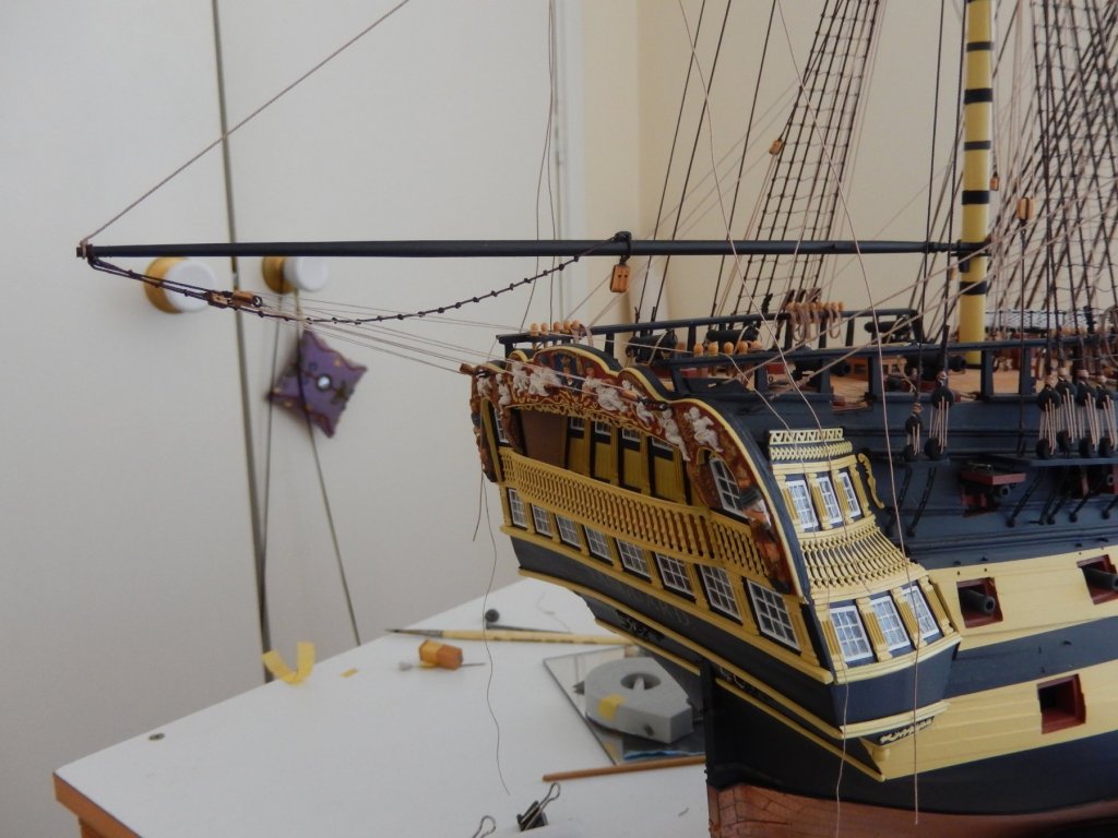
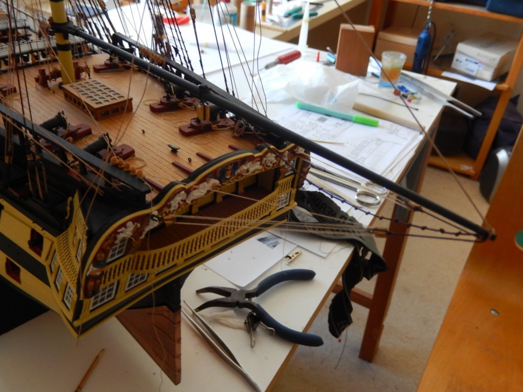
The repair has gone well - you'd never know .... However mounting the driver boom proved to be a bit of a nightmare. There are a number of traps and I fell into all of them. The main thing is to avoid the rigging fouling the lanterns and their supports. I didn't. I drilled the holes for the eyelets about 1.5 - 2mm too low. Fortunately the mistake is under the hook and the rigging and is not noticeable though I will probably try to repair it. This shows more the chaos of my work table than the boom. Make sure the driver boom clears the middle lantern. Mine didn't. The plans show the boom parallel to the waterline. Best make it to be at a very slight angle. Without the saddle, the whole process would have been far more difficult.

-
Amati's Vanguard is is very high quality, good instructions but is quite demanding. If you have two or three years to spend on it, the time is well worthwhile. After (I think) four years I have almost finished, You may find my build log in wooden ship kits forum if you're interested. Good luck rmc
-
Thanks very much Kier for the kind words. I thought at one stage your finger must have stuck on the 'like' button. I received the thread necessary to complete the rigging today, so I'll see how it goes. I also need to finish repairing the damage to the stern decorations. So far things look OK, but writing that is probably the kiss of death.
-
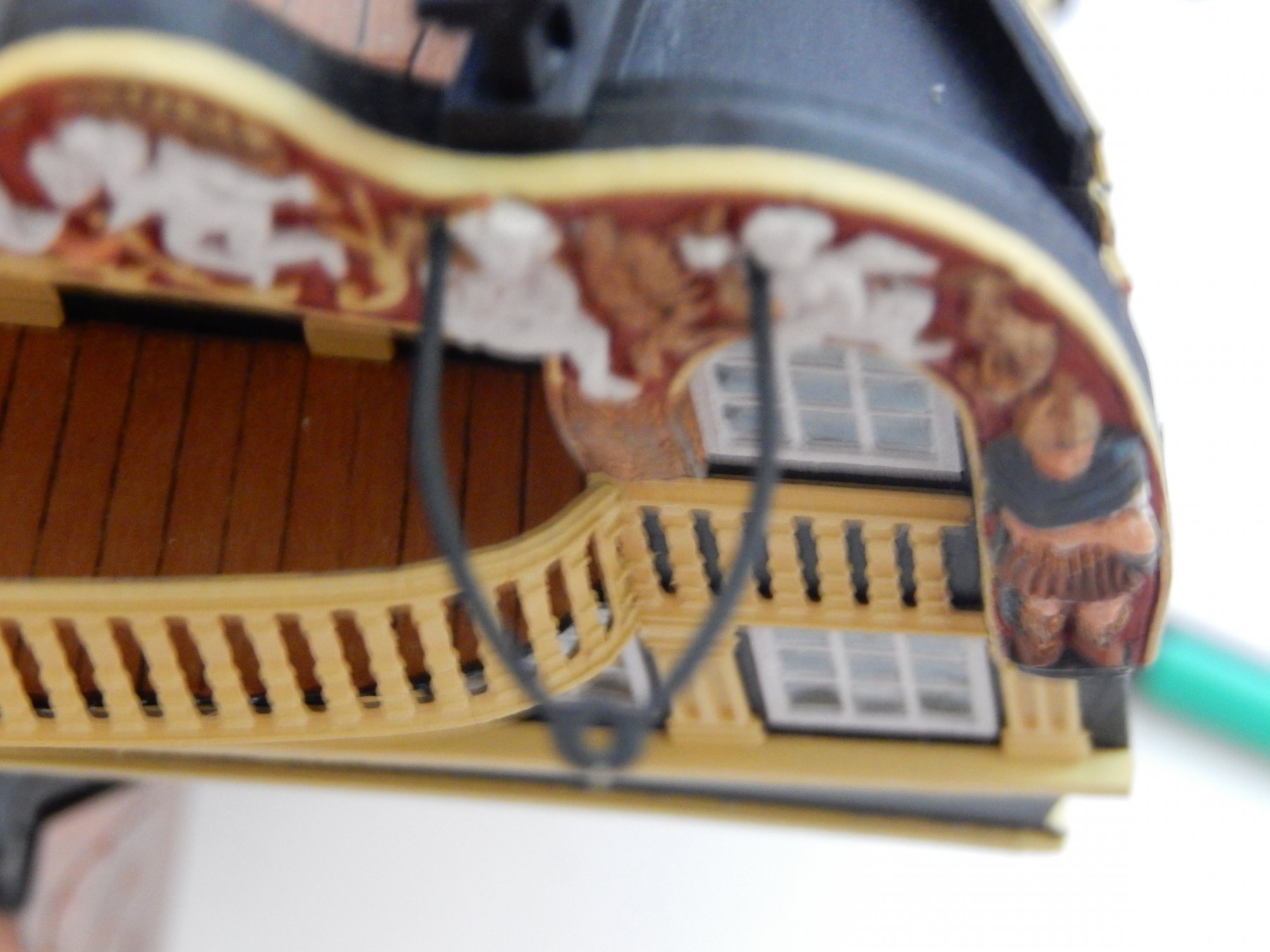
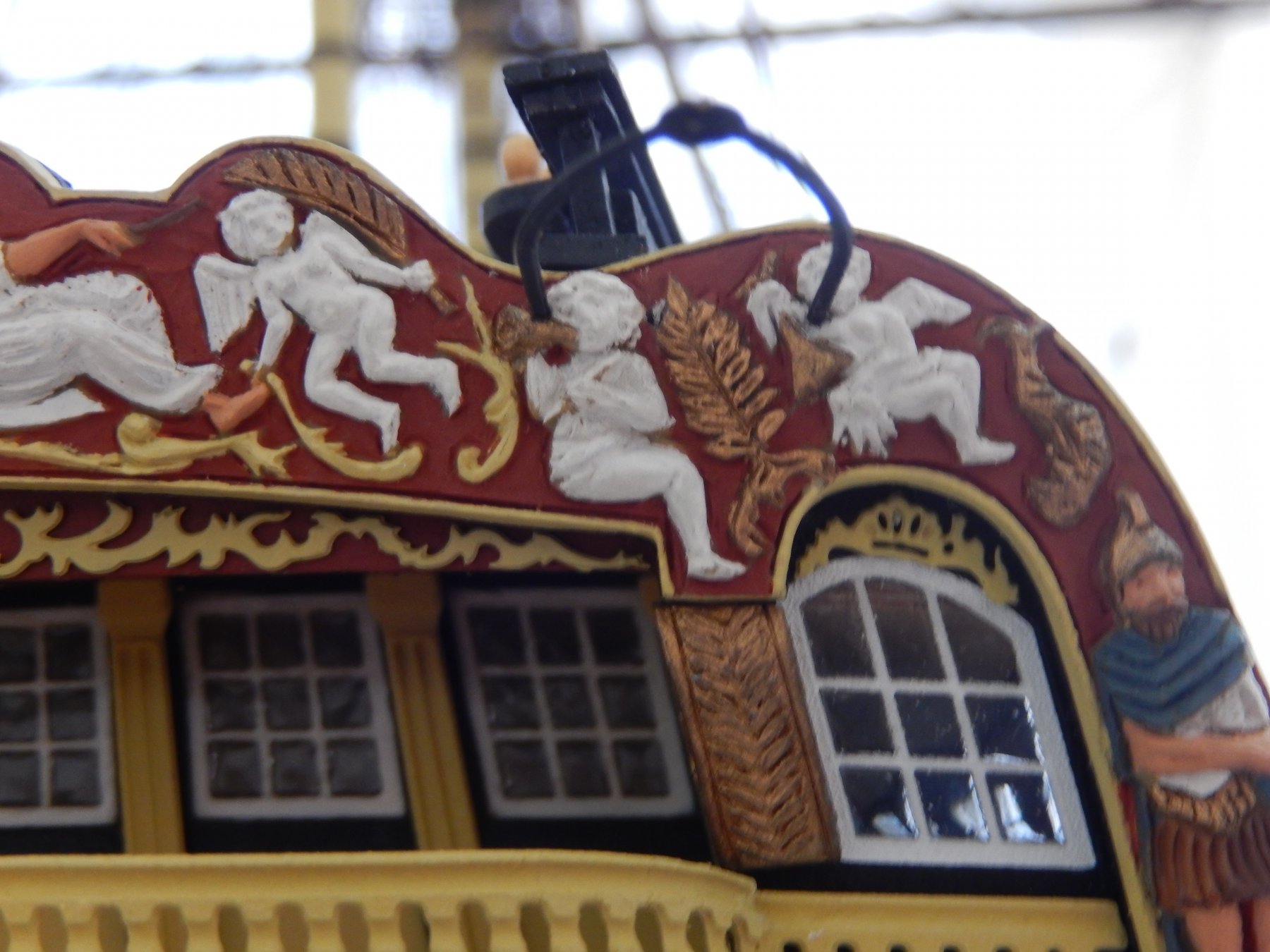
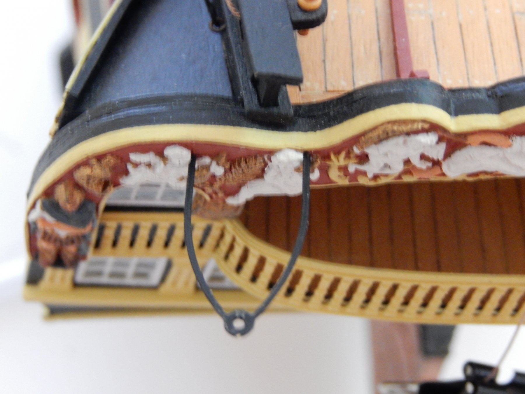
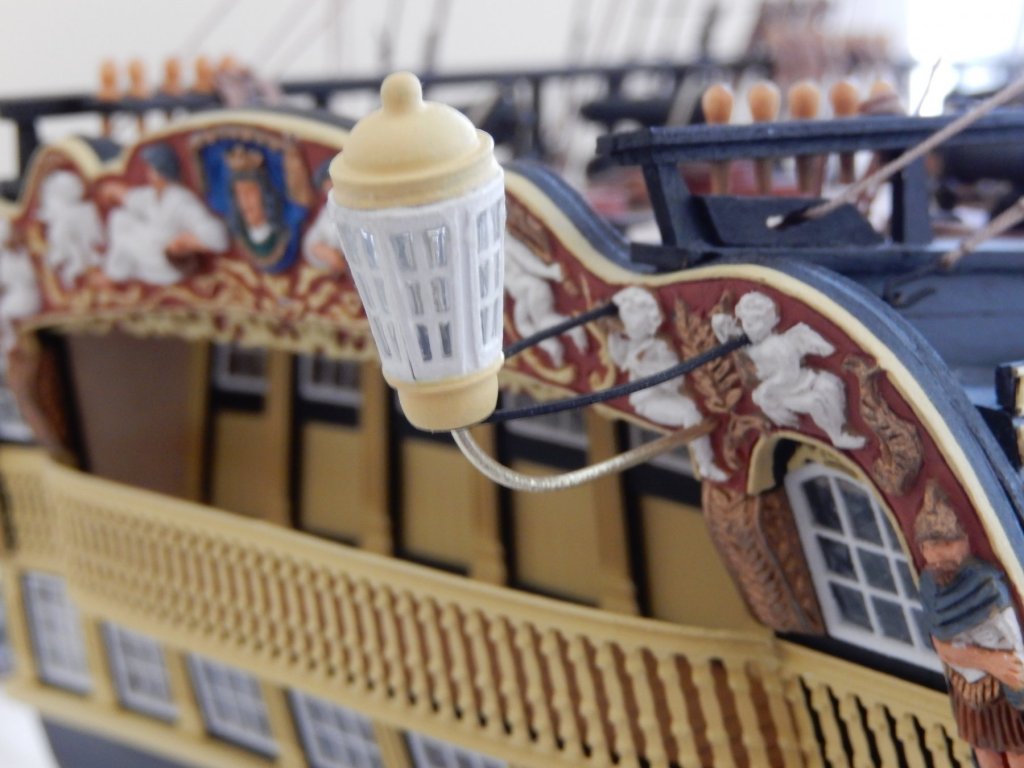
While waiting for the thread necessary to complete the rigging I thought I may as well see how the lights fit. This turned out to be what may have turned out to be complete disaster. While playing around trying to fit the starboard light, the decorative panel partially delaminated from its backing. This was not good at all. Having said 'Golly gee' (or words to that effect) I dropped medium CA and gel CA where I could into the gap, and held the two pieces together as best I could (clamping was not possible). At this stage the repair looks to be successful, but I would have liked to have got far more glue between the two pieces. The first and last photo below show the gap clearly. (I hadn't noticed it until I had taken the whole light assembly off the model and taken the following photos.) The gap has now been almost fully closed, the remaining gap filled, and a coat of paint put over it. Another two coats of paint and a coat of polyurethane and I hope nobody will know.


-
Thanks Jason. The photos show up every little fault, but in the flesh the decorations come up well. I have now finished drilling the 1mm holes for the vertical light supports which again is a rather fraught business. For those who have not yet mounted the decorations, I strongly suggest drilling the holes before painting and mounting.
-
A concern is avoiding the rigging of the driver boom fouling the lights. Exactly where the rigging is attached to the hull is far from clear. Actually installing the lights is about the last thing I will do as their attachments are very fragile indeed. Protruding as they do is an invitation to disaster. However to get an idea of the best place to attach the boom rigging I have dry-fitted the light supports - shown below. This entails drilling holes in the decorative surface of the stern - something I was not keen to do. However needs must ... (With hindsight I would have drilled the holes before painting and off the model, but there your are.) In the process however, I discovered that it is just possible to drill the appropriate holes without damage to the painted figures. Obtaining the distance between the holes from the light supports, I used a pair of dividers to search places on the decorative surface where I could drill without damaging the figures. The only places are shown in the unfortunately rather unclear photos.


-
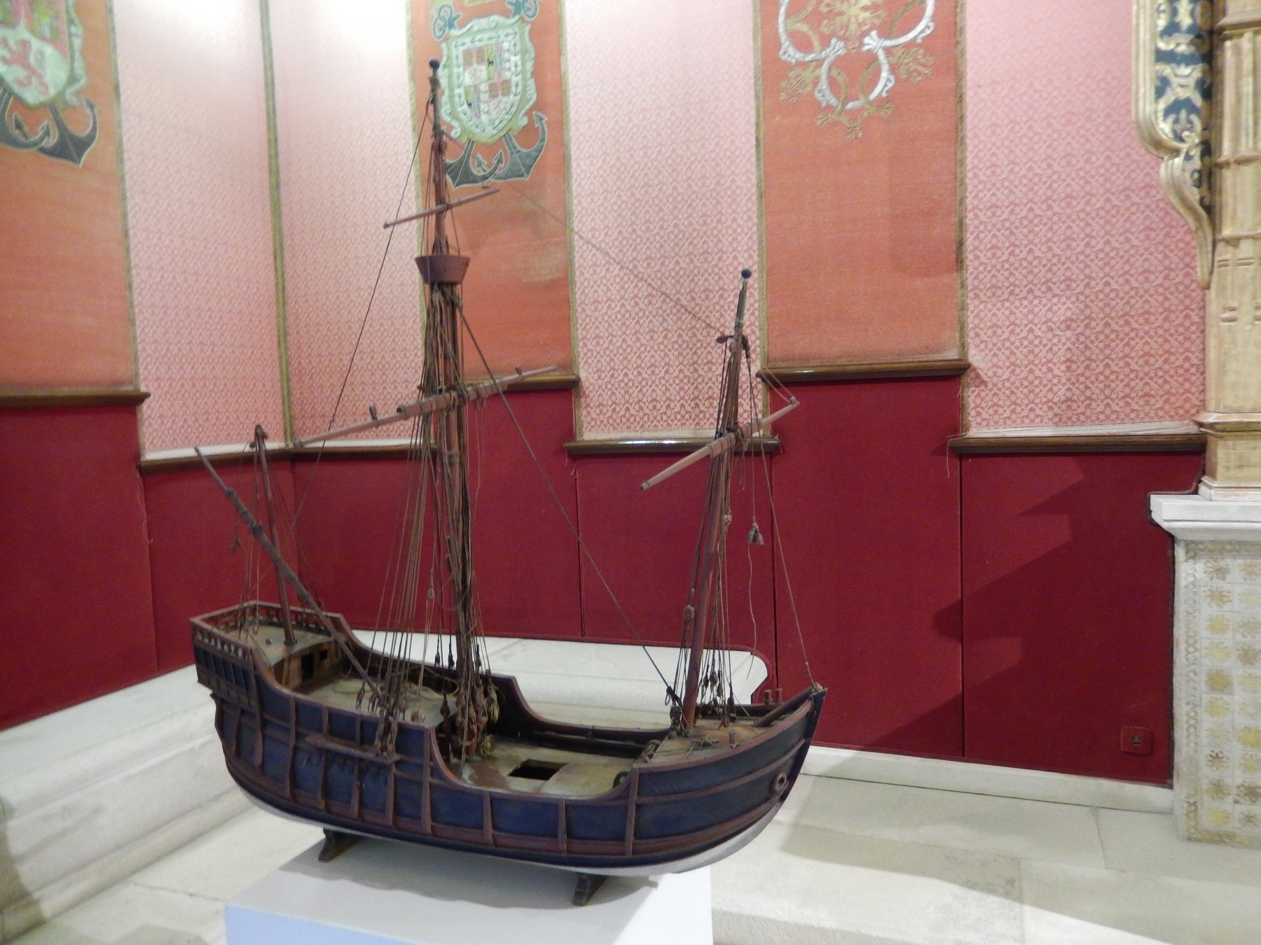
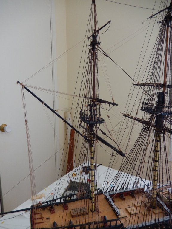
Windows 10/Nikon software is continuing to be difficult. This is an experiment to see if I can more easily load photos following an upgrade of the Nikon software. Joy - it works. The photo is of a model of the Santa (sp?) Maria from a museum in Valencia. Finishing off the rigging of the vanguard will have to await the arrival of the Syren thread in a couple of weeks.

-
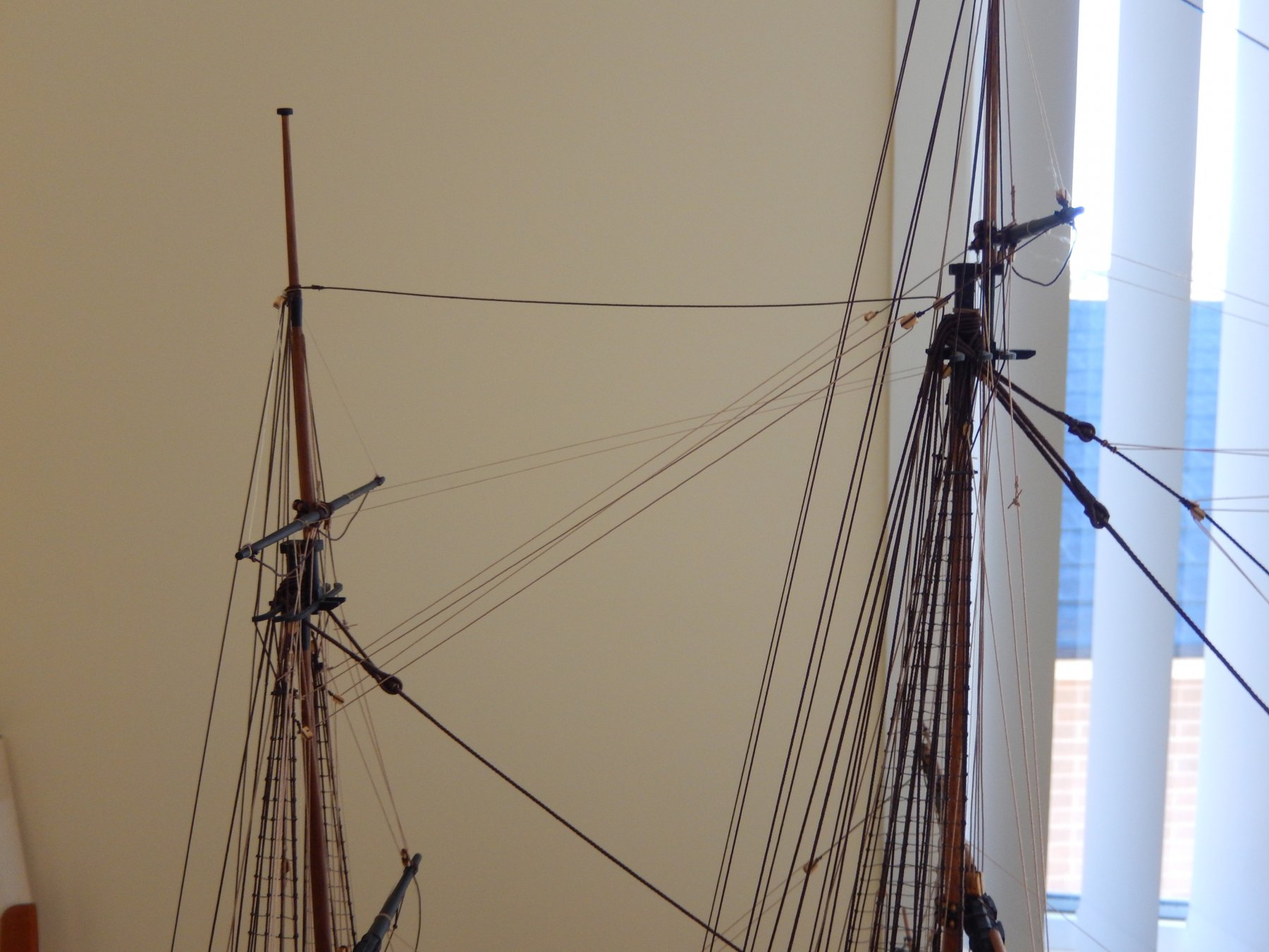
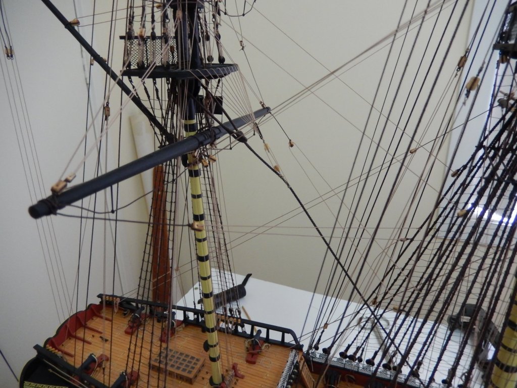
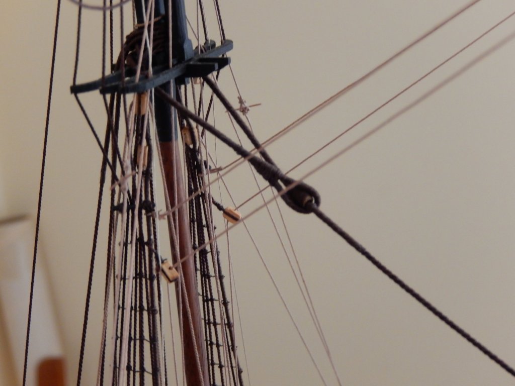
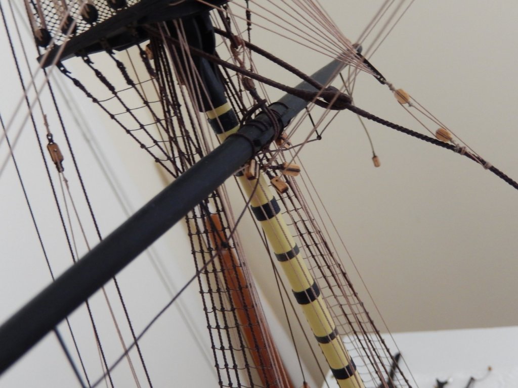
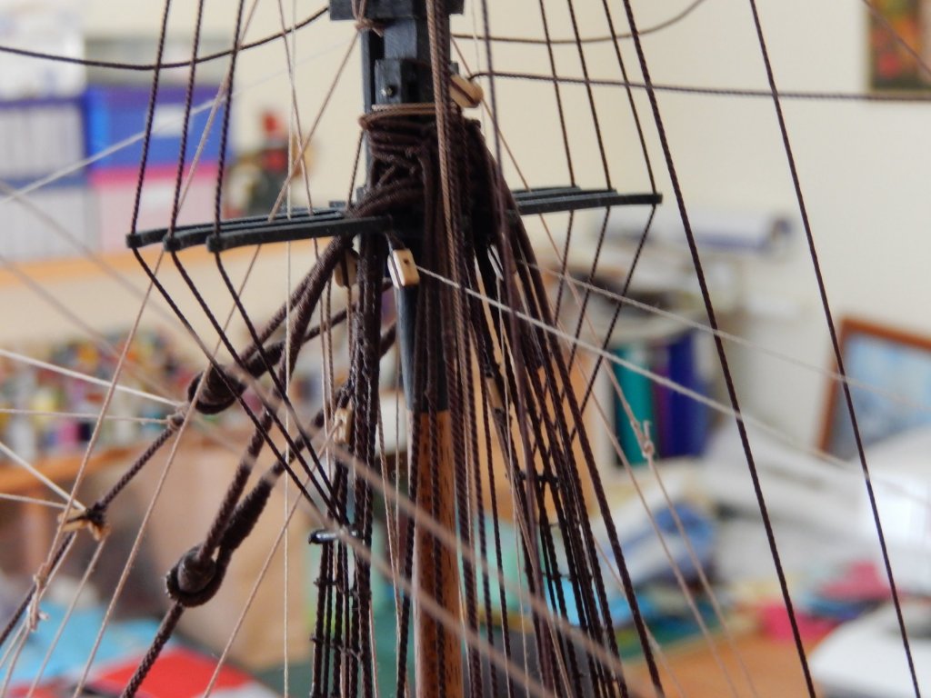
The braces are now finished. The driver boom(spanker?) is the only bit of rigging that needs to be done and it will have to wait until I receive a (very) little more 0.47 thread from Syren. I have tried to show the rigging of the braces in the following photos, but I'm afraid it doesn't show up well. They may be of use to someone though. One thing that may come across, however, is the complexity of the rigging of these ships.
-
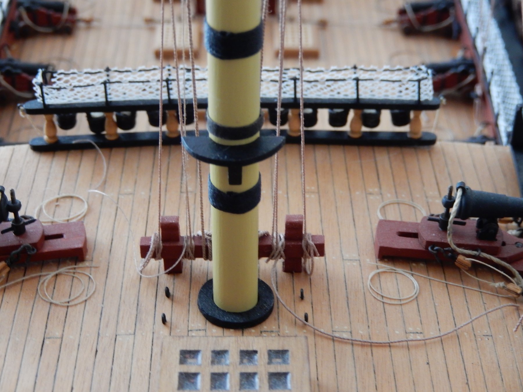
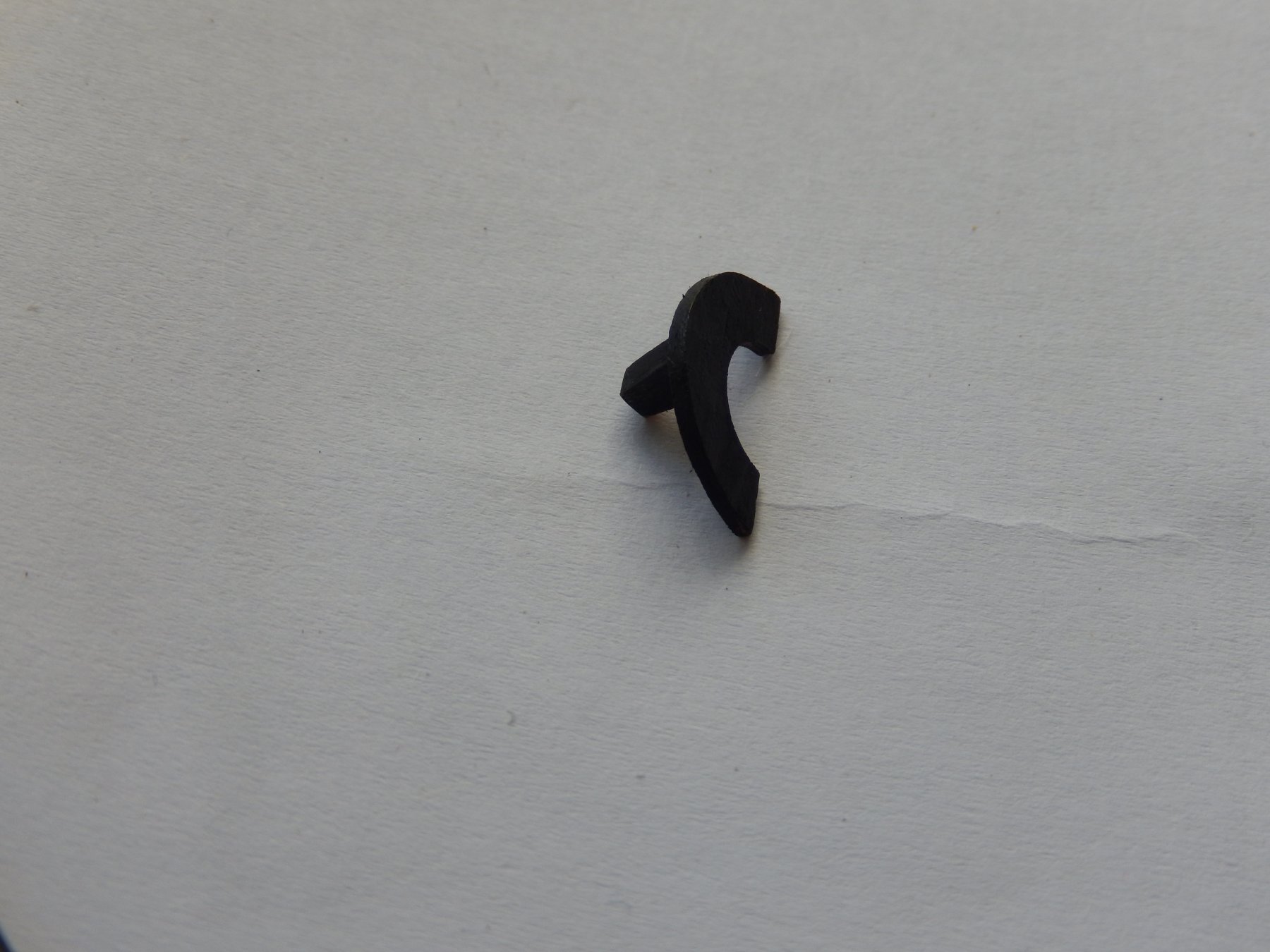
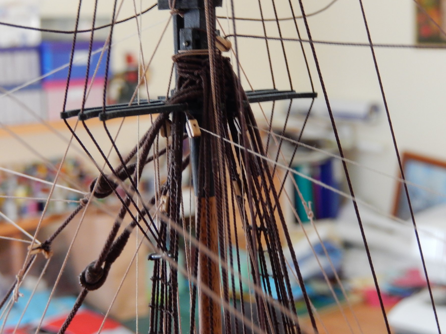
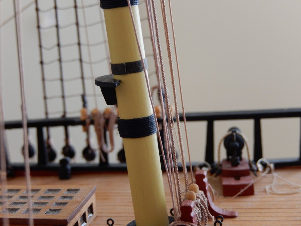
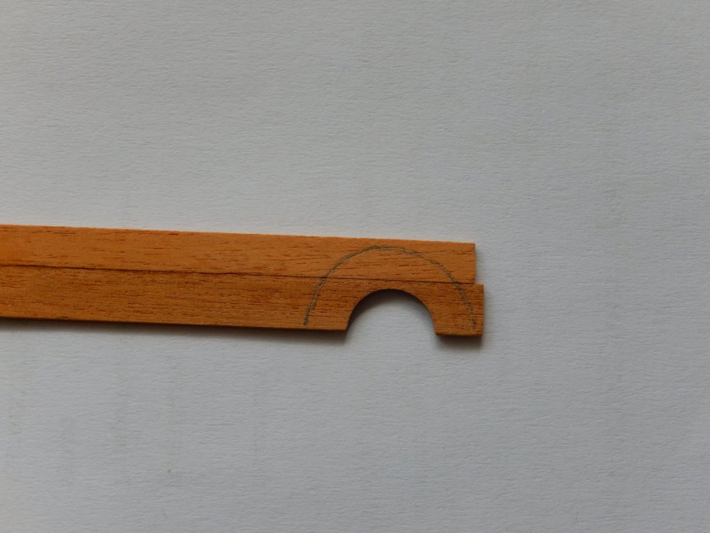
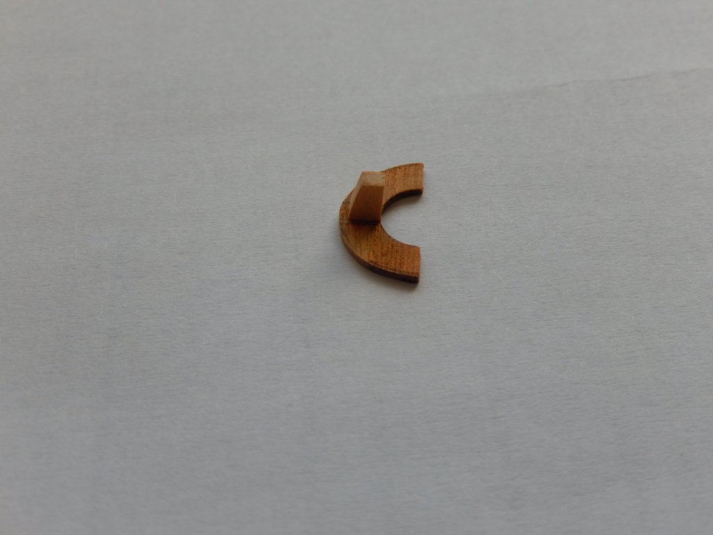
Here is the saddle attached to the mast. It's shape is more or less a guess. If it turns out to be wrong, at least the mistake won't be all that obvious. In the photos below the boom is simply resting on it to give the general idea. I have run out of 0.45mm thread (by about 20cm ) so I will have to order more and finish it when I return.


-
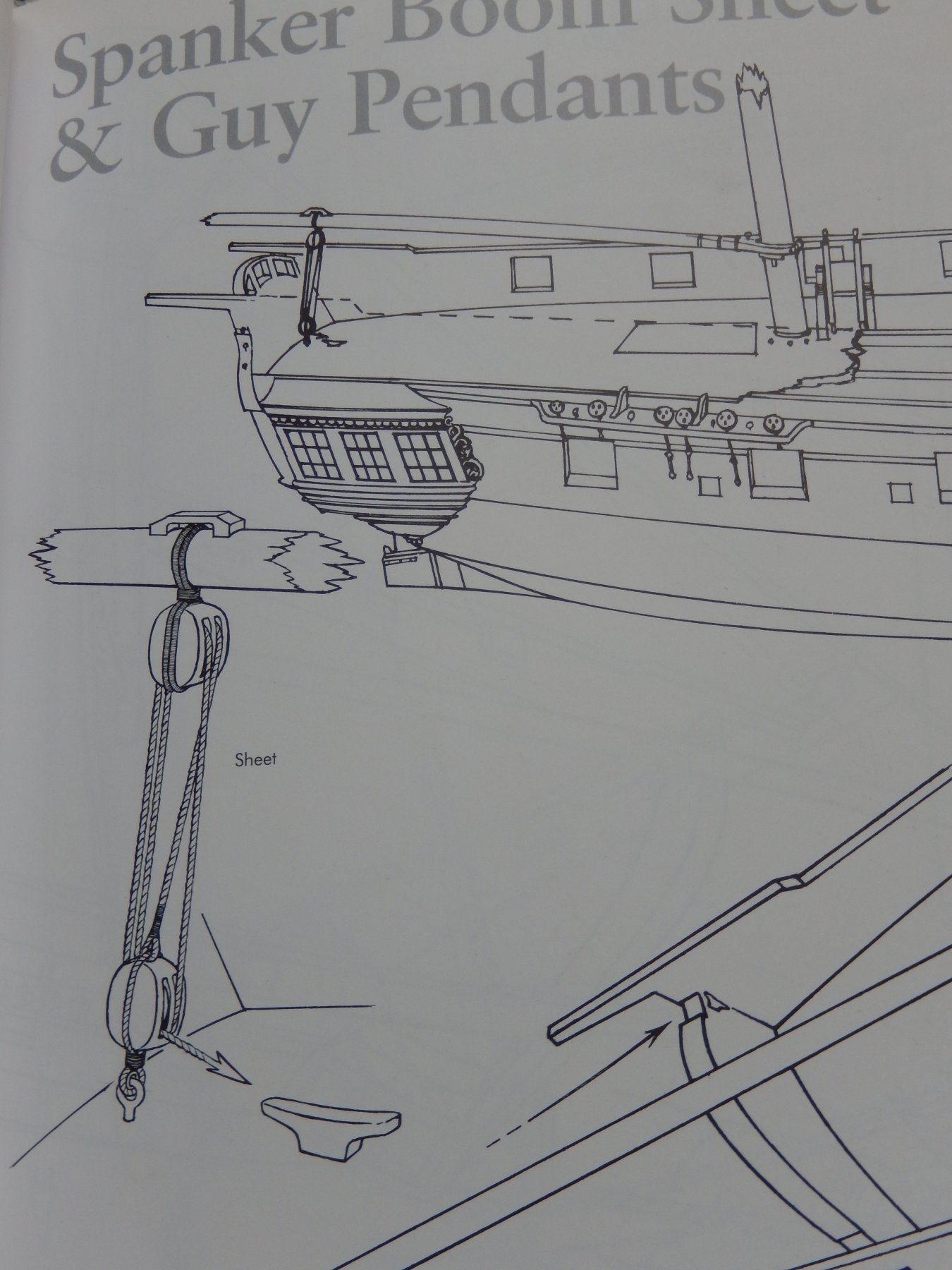
The lower (boom) Peter. I have seen an illustration of what turns out to be the gaff throat halliard as you have described it, but there was no name to be found (or at least I couldn't find one). Fitting one now isn't possible, and even if it were, it's probably not worth the trouble. I hope to have the (lower) saddle fixed before I go away (to Barcelona) and if so, Ill post some photos. All the best Bob
-
The driver gaff is now attached and so far has turned out quite nicely. Keeping the gaff 'attached' to the mast was a bit tricky - it kept moving up and down as the lines were adjusted. I understand a saddle was meant to slide up and down the mast to control this, but there is no reference to anything like this in the plans. The only drawing I have been able to find is not practical at this stage of the build - so here, no saddle. On the other hand, attaching a saddle for the driver boom looks to be comparatively easy. Here it is with the first coat of paint - sand back, another coat or two and some polyurethane will finish it. Then all I have to do is get it on the mast ..... I had hoped have the driver boom attached before I go away next week, but I have just run out of the Syren 0.47 thread that is needed.

-
Peter (flyer): sorry for my delay in replying. Things are a little busy at the moment. Since your post I have looked at Petersson - something I should have done in the first place. It shows pretty well what you have gone to the trouble to describe. Sorry about that. I wouldn't have resorted to Petersson had I not had your suggestion. Suggestions/comments are always helpful. (Note the 'first place' next to the photo- I have no idea how to get rid of it.) first place.

-
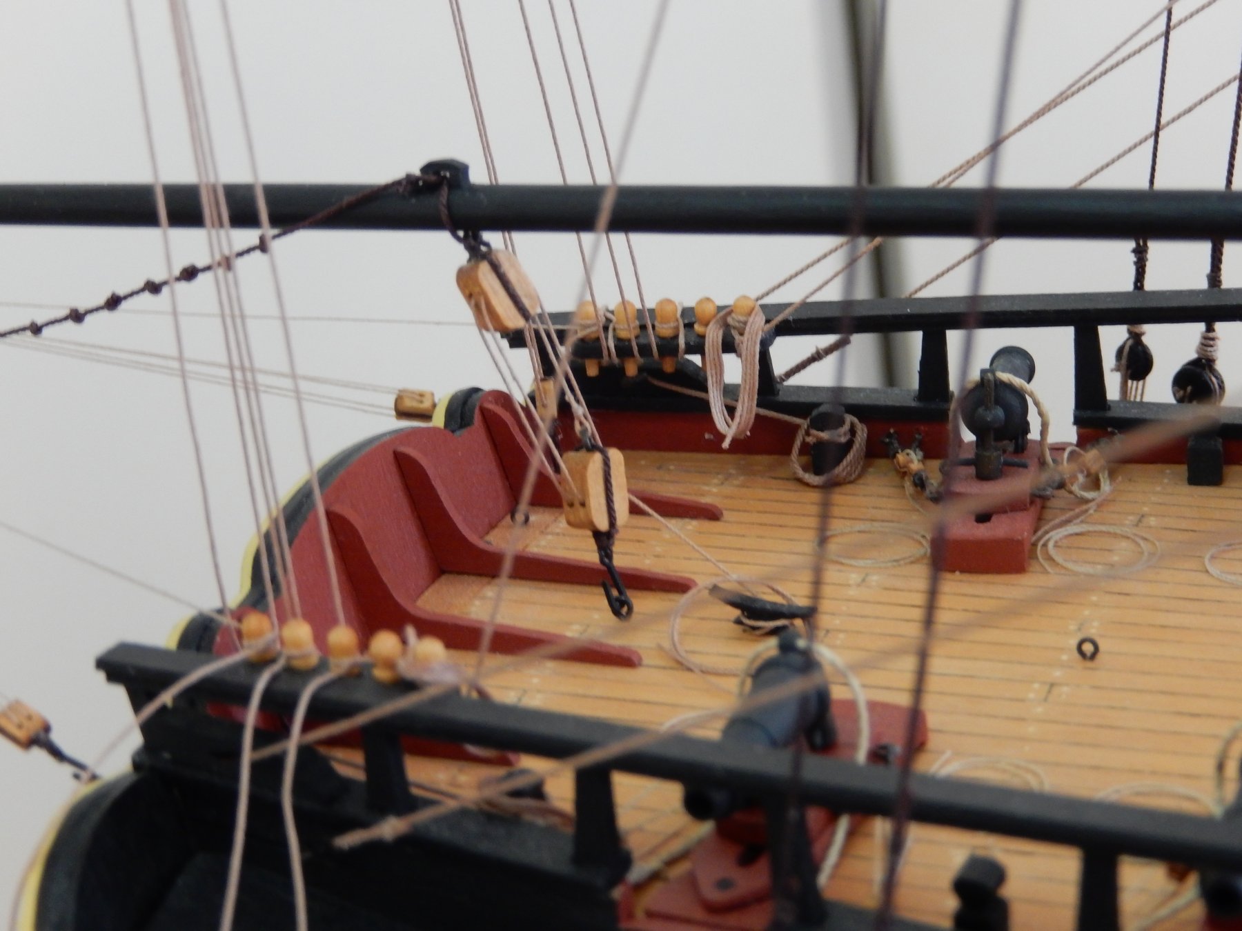
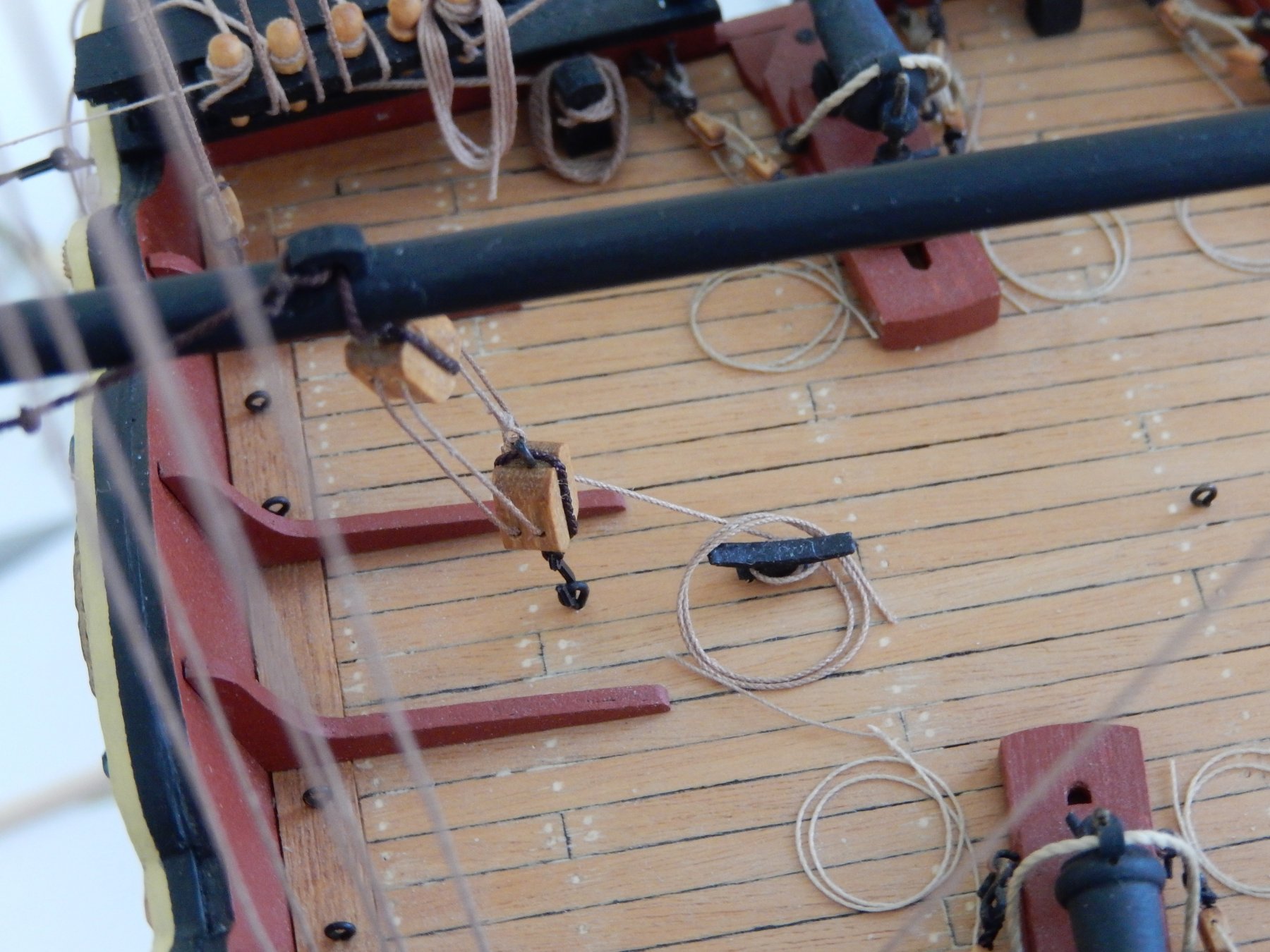
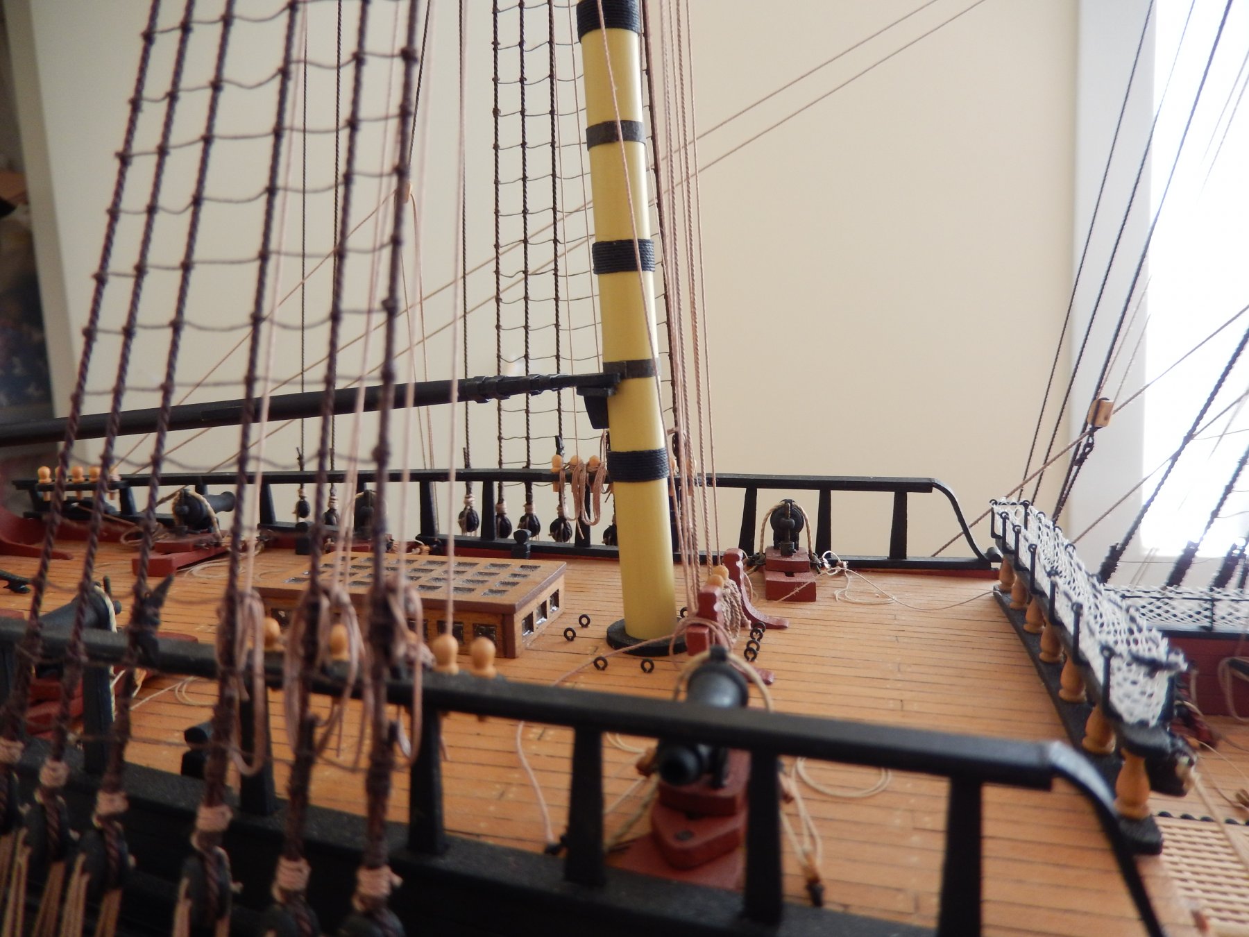
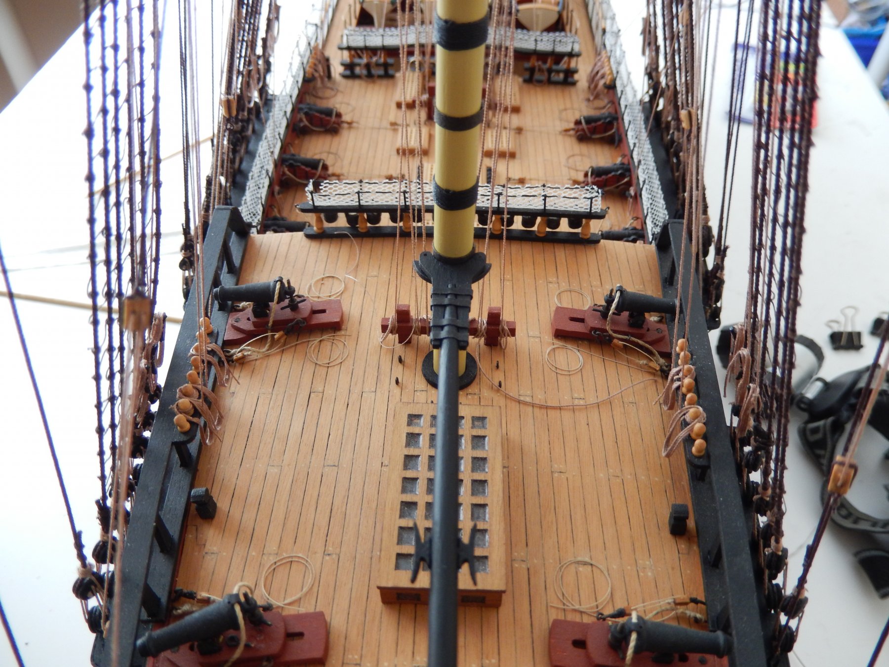
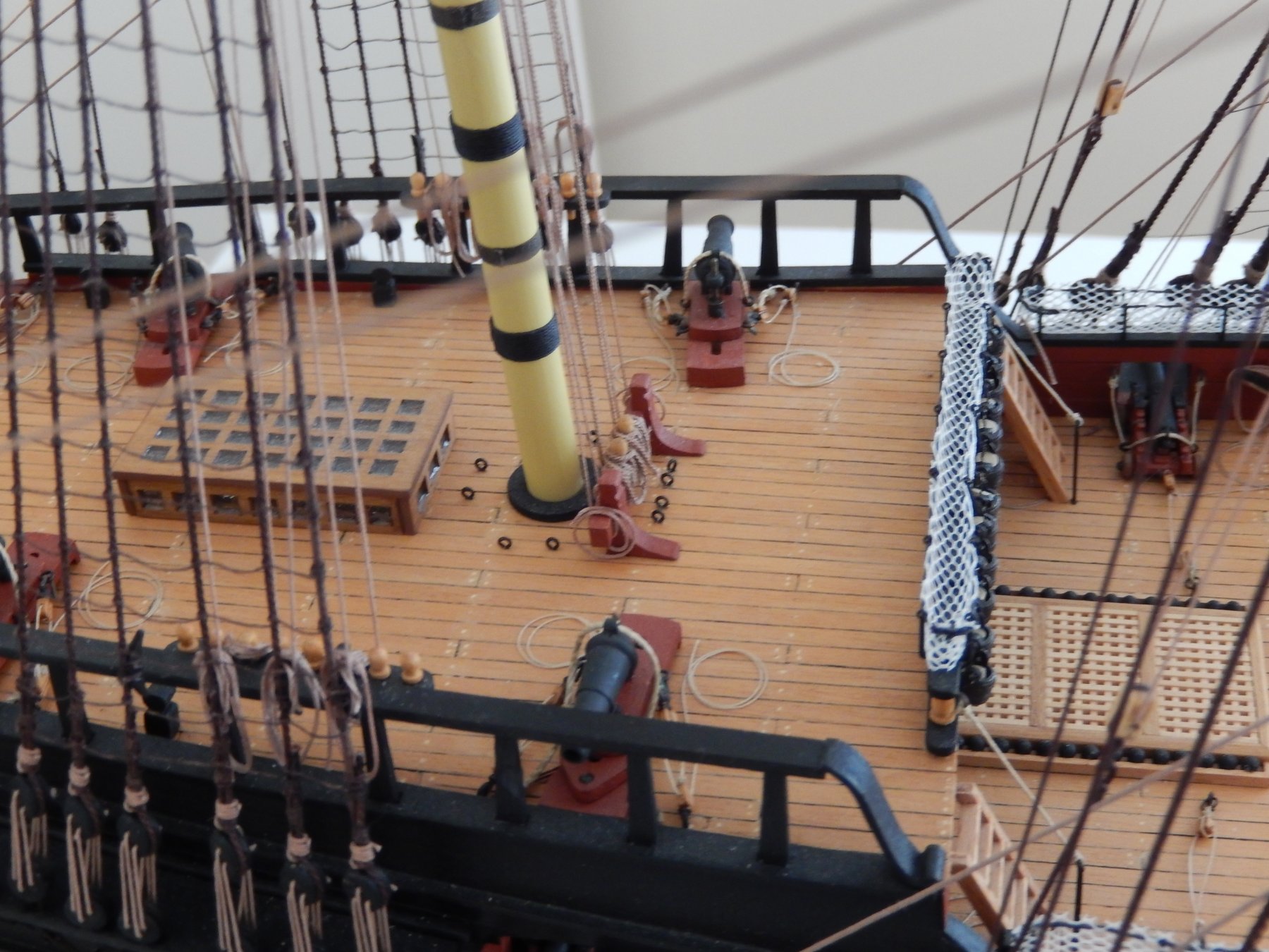
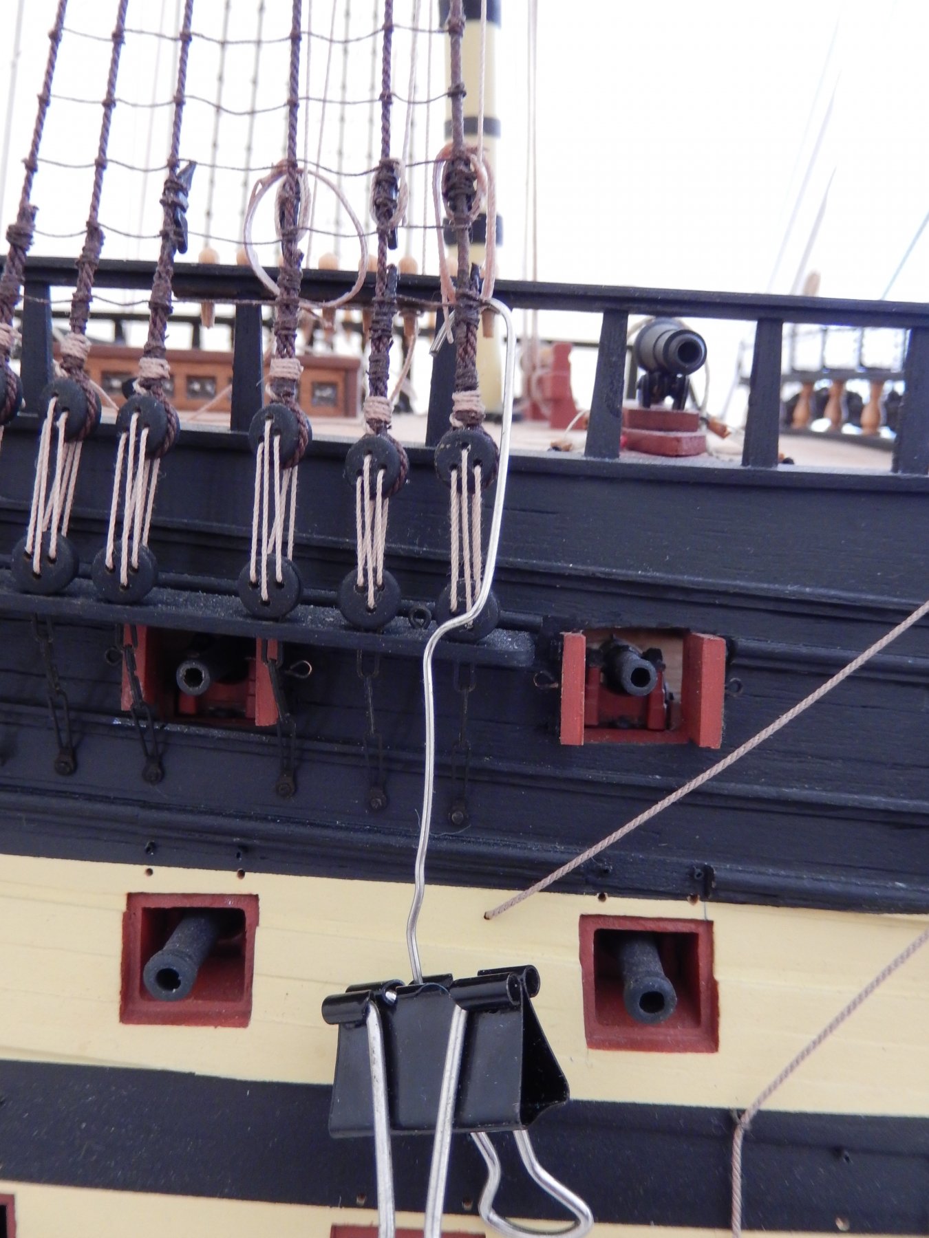
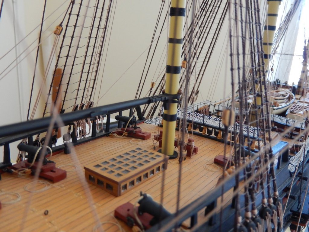
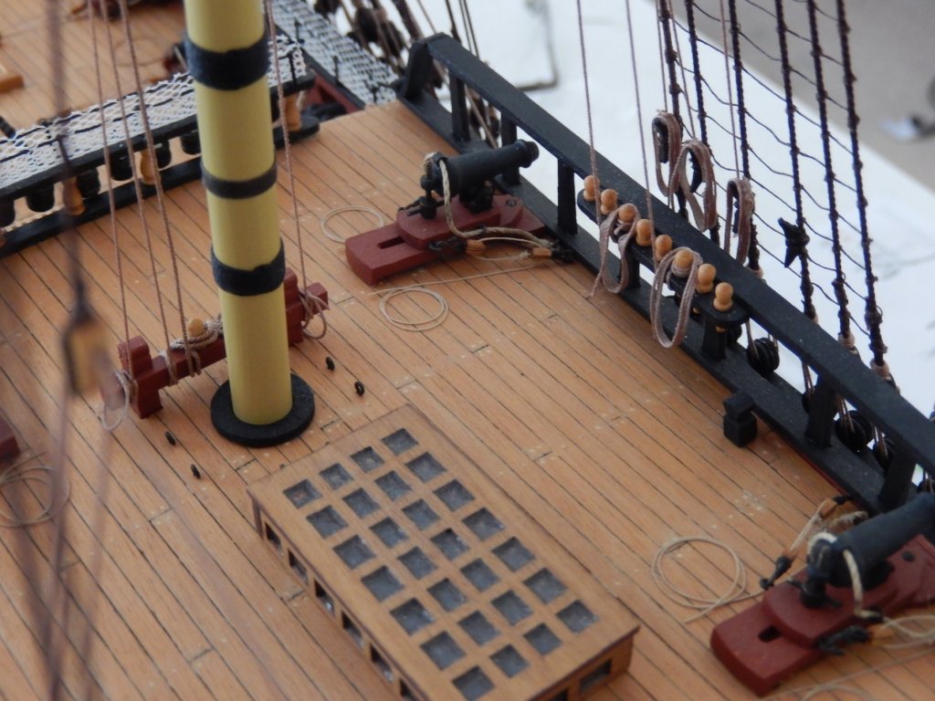
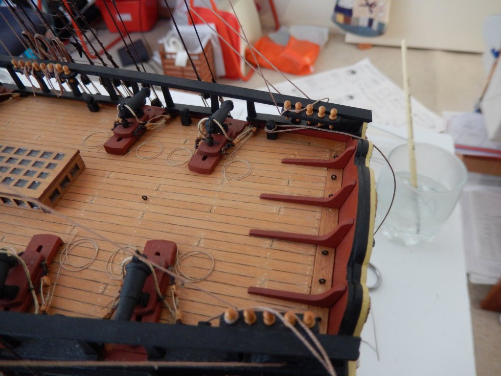
The rigging of all but the mizzen mast yards is complete. This is how the poop deck looks at the moment. Rather foolishly I overlooked three or four lines still have to be belayed on the bitts below the mizzen. So there is still work to retrieve that omission. Below is one of the main braces. Thanks to Flyer for informing me how they should be belayed. There is, in fact, a small hole already in the block mounted on the bottom of the rail ... ... the line is threaded through and belayed to the post on the deck shown below. (The line has not yet been finally tied off and a rope coil needs made.)
-
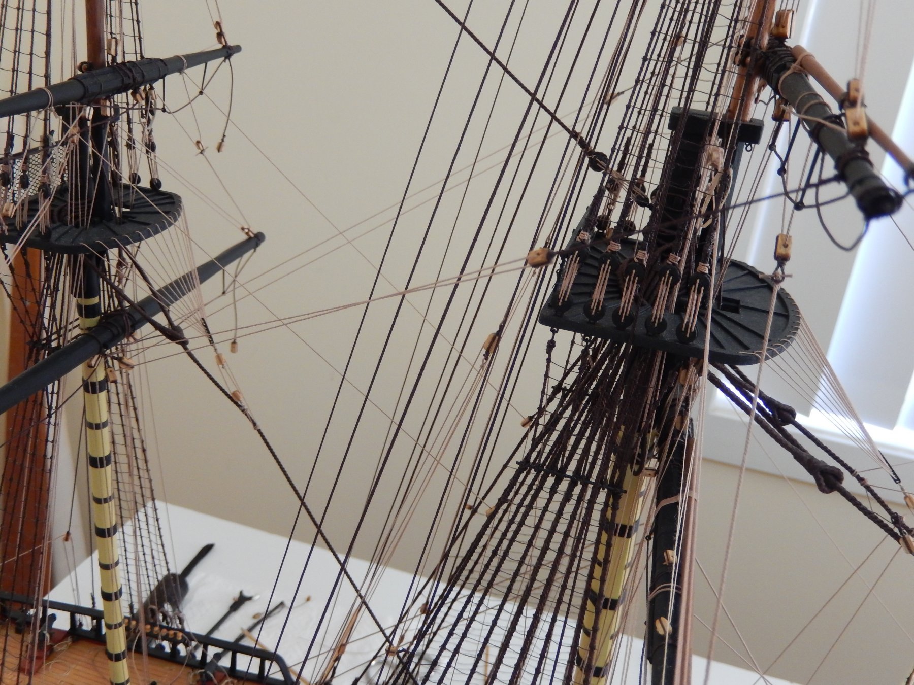
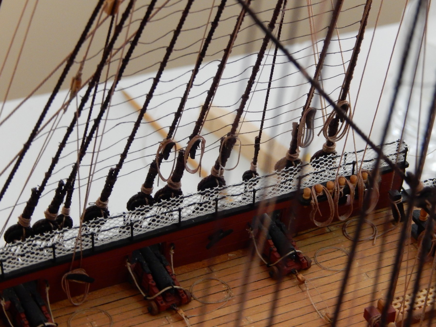
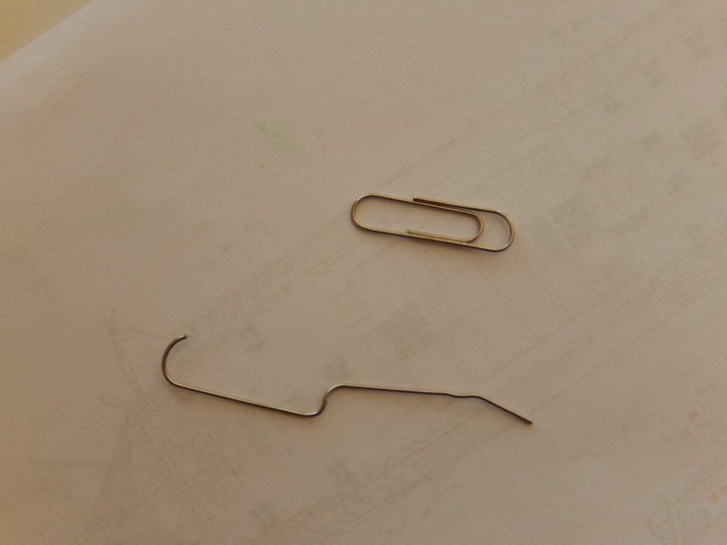
As far as I can tell, all of the lines that should be belayed at or near the main mast are now been finished. The bowlines and braces are all but complete. Until doing all of this I had no conception of how complicated was the rigging of one of these ships. I'm not sure if the following photos are of help, but I have tried to show close-ups of some of the more difficult bits. The bow lines go to belaying point 75 and 76. Here are the bow lines to belaying point 76. The lines going into the two blocks shown below were a small nightmare to thread hidden as they were in all of the standing rigging. I put off tying the braces to the main top yard shown below as long as possible. I had left the lines tying the blocks to the mast a little short, and thought tying the running rigging above the blocks would be quite difficult. It turned out to be simple. Make a noose, slip it over the block, then tighten the noose. This may help those who must attach rope coils with some semblance of natural 'hang'. I first made circular coils in the way I described earlier using the plastic nozzles. To give the 'hang' I first wet to circular coil in situ (using a small paint brush) then used a paper clip and a light weight to draw the circular coil down. Here the left coil has not yet been touched; the right is pulled don by the weight. Here are some results, though I see some further adjustments need to be made. I will be going away for a while in a couple of weeks and in the meantime will try to fit the driver gaff and boom. (I have no idea why the preceding sentence is underlined.


-
Sorry for the delay in replying CDW. I don't have Opera and I can't find a box similar to the one you describe in any of the search engines to which I have access. I guess I'll have to stick with Microsoft Edge (when it works) or Google Chrome. Thanks too Mark for your comment. The whole thing seems very odd.
-
Zappto: Yes, the small boats are wooden. On another topic. - I have had trouble with both Fire fox and Google in posting replies. When I click on the reply button only the 'drag files etc' is apparently operative and will not allow any text to be inserted. Google chrome seems to work properly as does Microsoft Edge (but it has other problems). Does anyone else have the same problem?
-
Painting Photo Etched Parts
RMC replied to michbyerley's topic in Painting, finishing and weathering products and techniques
I am close to finishing Vanguard. I have found the brass etchings may be cleaned first by etching with the finest steel wool, then finally cleaned up with acetone - then use an undercoat before painting. For any blackened parts, after cleaning with steel wool/acetone, use Birchwood Casey Brass Black. Good luck rmc -
Having more or less completed the rigging of the fore and main masts and yards, I had though the mizzen would be ..er.. plain sailing. Alas, it has turned out not to be so. Avoiding lines fouling each other proved quite difficult - only after some lines were 'finally' tied off was it apparent that they had interfered with others ... It has been two steps forward two steps back. I am quite short-sighted, which in this application is an advantage, so good luck to those who are long-sighted. I will post some photos in the next day or so, though really it's more of the same (ie: fore and main rigging) so I don't know if this will really help anyone. At least now it seems to be under control and it's time for a drink ... or two ....
-
Peter: thank you VERY much for the information. It would never have occurred to me. Bob
-
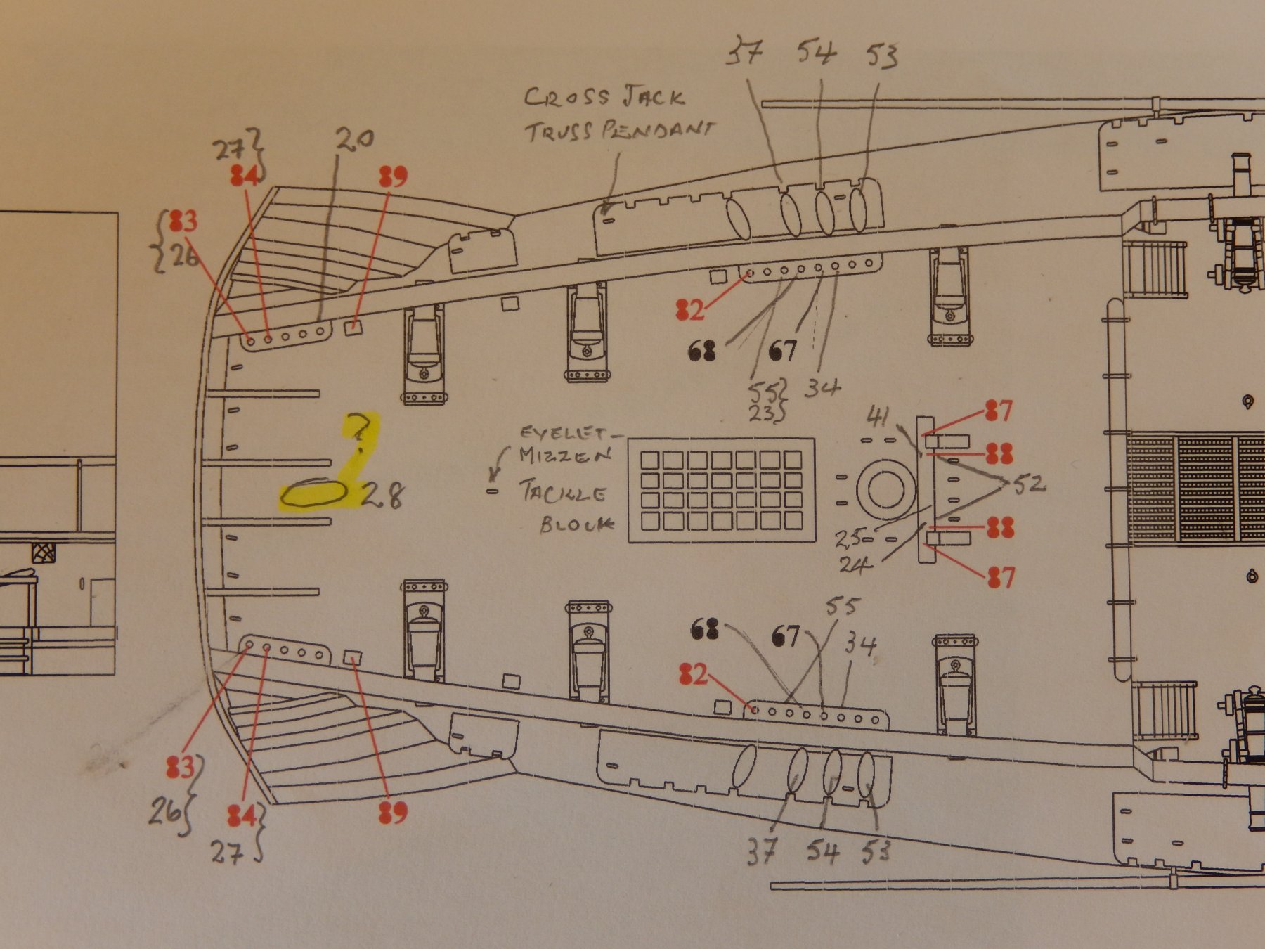
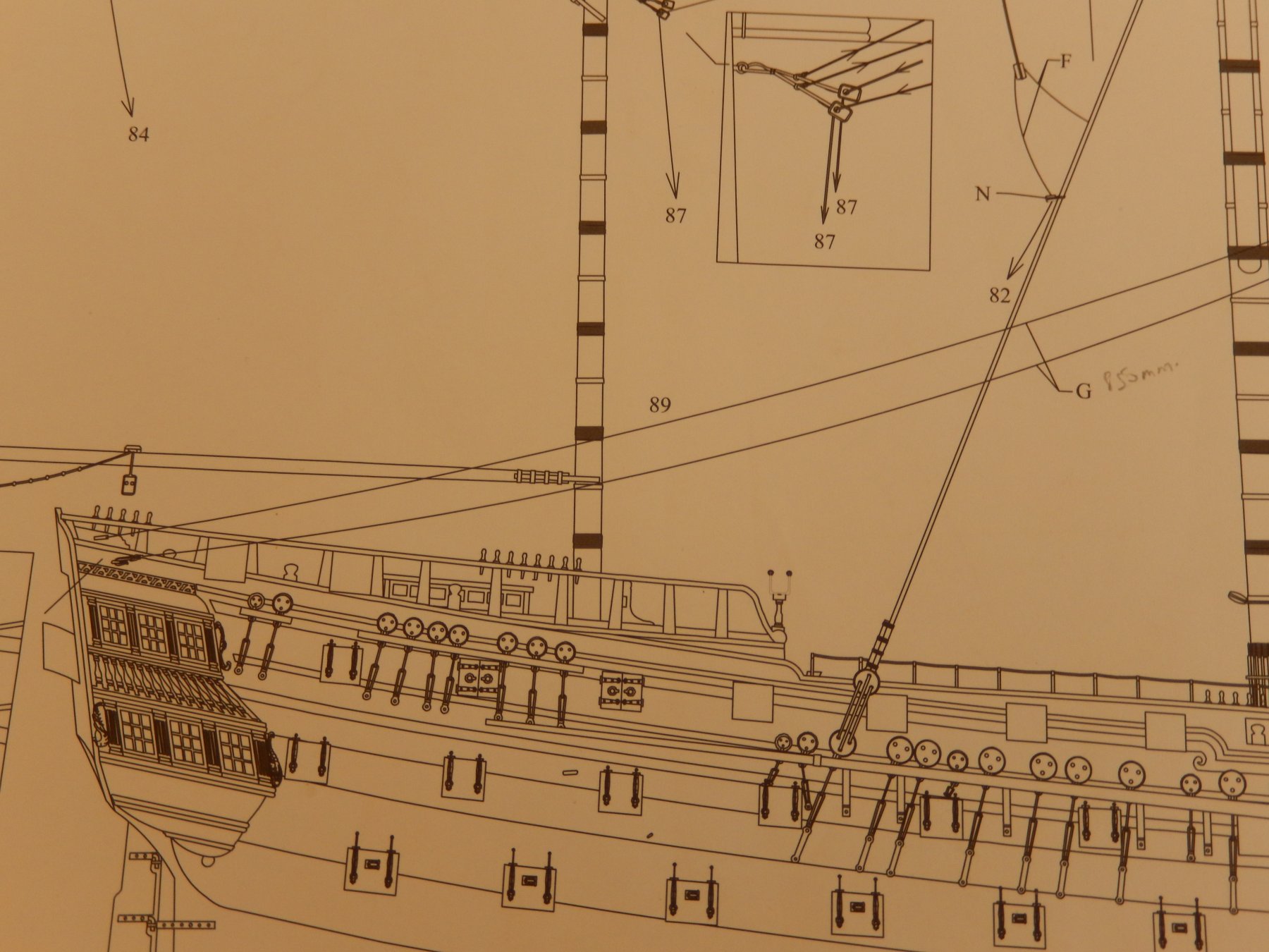
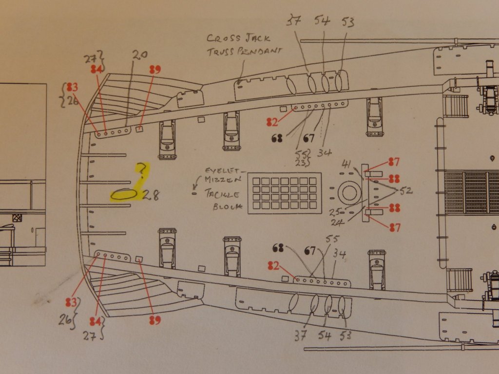
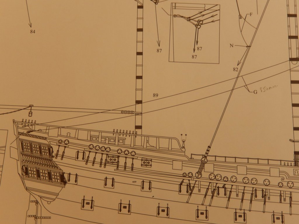
If I expected the rigging for the mizzen yards to be a little less complicated the yards for the fore and main, then I would have been sadly disappointed. It is of course every bit as intricate with the usual degree of awkwardness. Here are the belaying points. Those marked in red were originally omitted from the plans and subsequently added by the designer, Chris Watton. I have no idea what the oval marked 28 is supposed to be. There is nothing on the plans that I can find, though as I can rarely find anything, perhaps this is hardly surprising. As usual many of the belaying points are doubled up. Then there is an added complication. The braces for the main yard are shown below as apparently belayed at 89 - on the side of the hull. Point 89 shown above however is on a post on the deck. Unless something else shows up, I will ignore the belaying point on the post.
-
Deck Planking
RMC replied to michbyerley's topic in Planking Techniques's Click Here for Topics dedicated to planking!!!!
The brand is 'Woodcraft' made by Kuretake Co Ltd Japan. I used the chisel tip 6mm. It is very easy to use and has all the attributes of the Brush described above - acid free etc. ..... I guess you pay your money and make your choice. I am just about to go away for a few days and haven't the time to include a photo. All the best wiith your vanguard. rmc (Bob) -
Deck Planking
RMC replied to michbyerley's topic in Planking Techniques's Click Here for Topics dedicated to planking!!!!
I am in the finale stages of building the Vanguard. For the deck planking I used a Woodcraft Marker. They are made in Japan, and in this country are available in craft shops. I think they are also available at Modeler's Shipyard near Sydney. They have a website and do mail order. You can have a look at the results by taking a look at my Vanguard log. All the best rmc