HOLIDAY DONATION DRIVE - SUPPORT MSW - DO YOUR PART TO KEEP THIS GREAT FORUM GOING!
×


RMC
-
Posts
933 -
Joined
-
Last visited
Content Type
Profiles
Forums
Gallery
Events
Everything posted by RMC
-
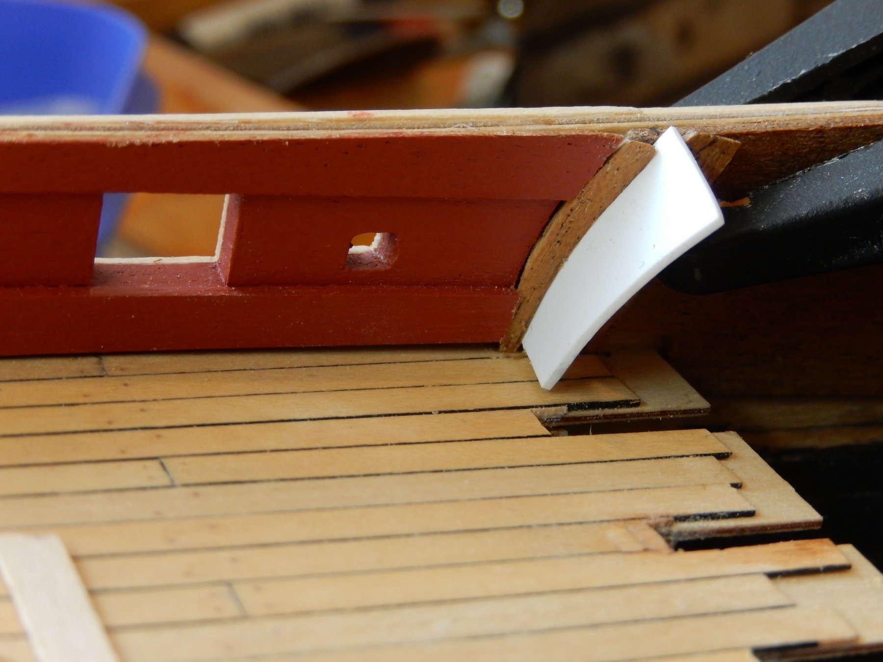
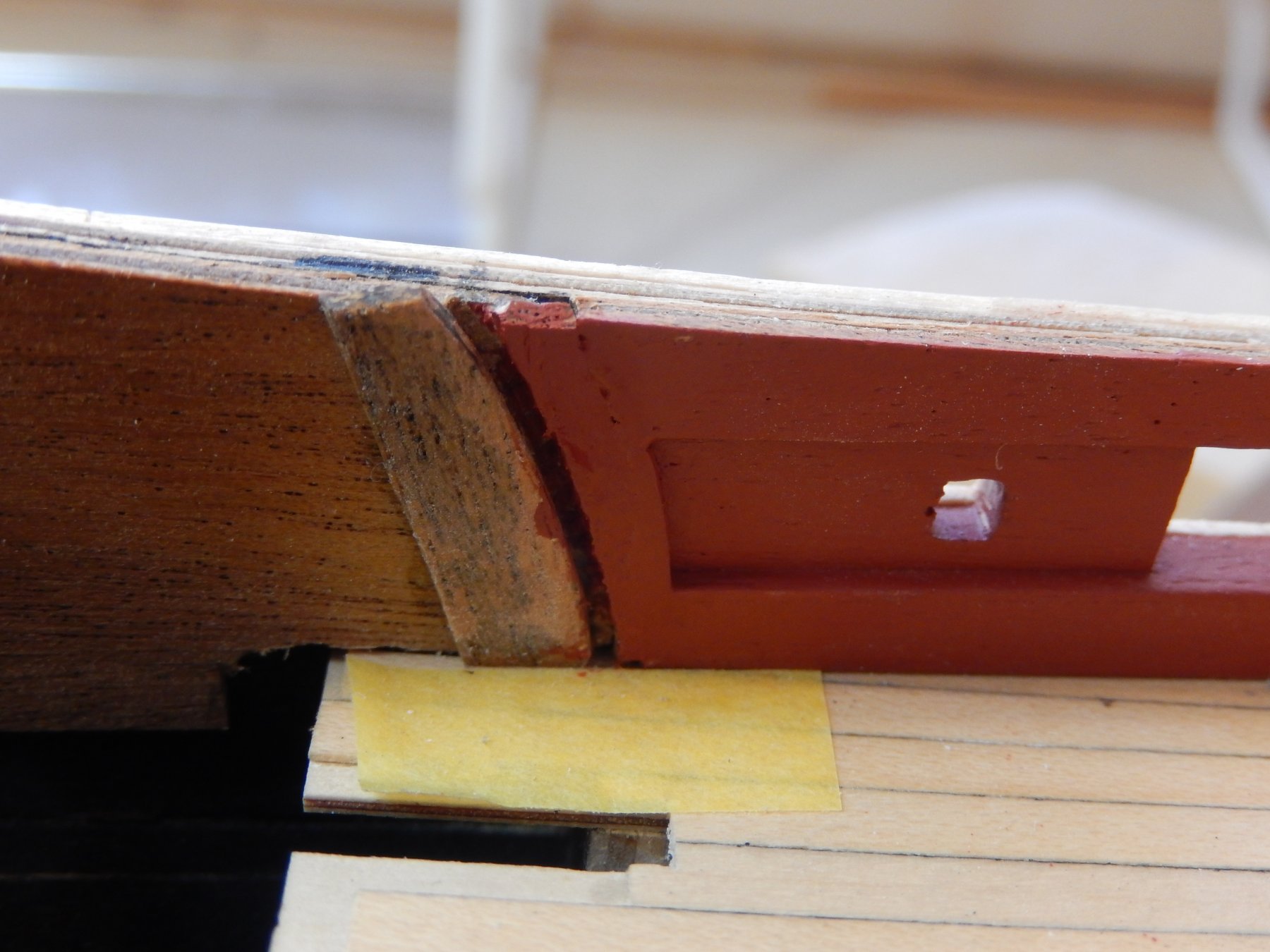
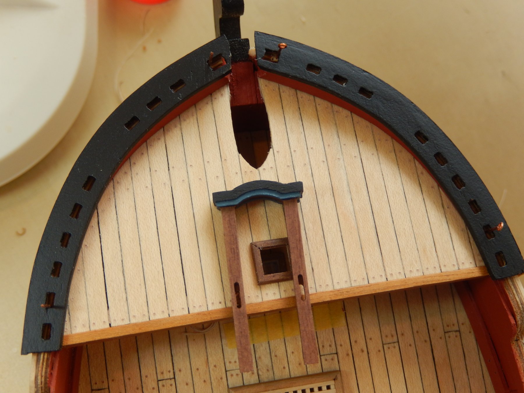
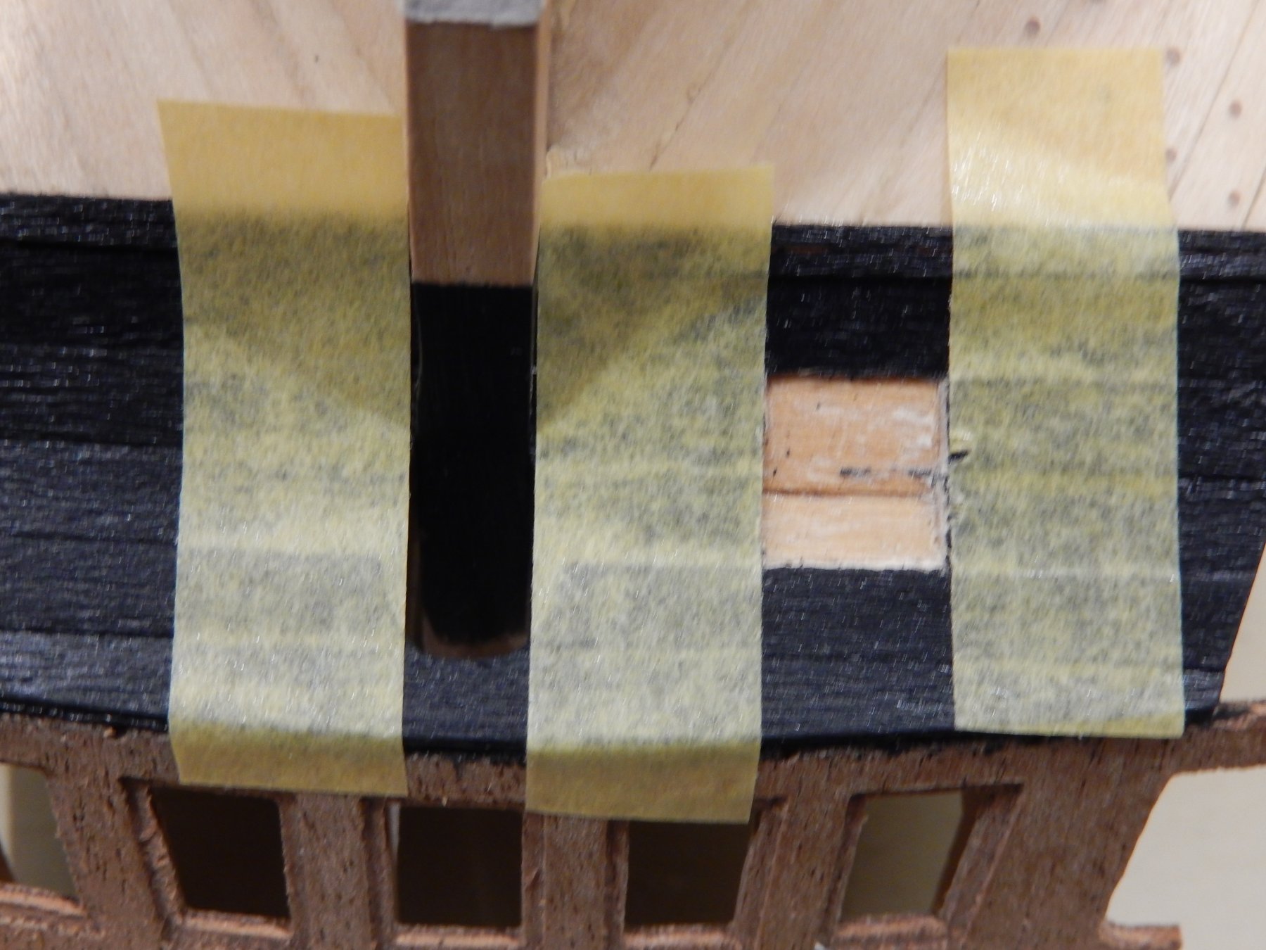
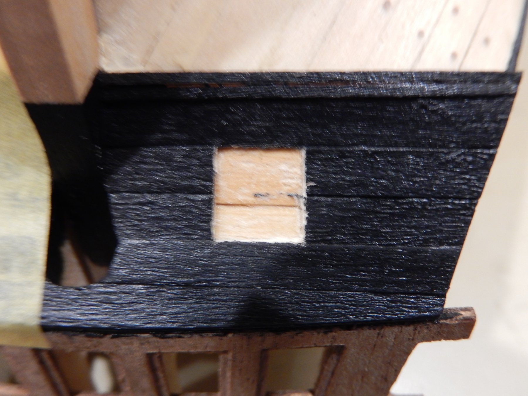
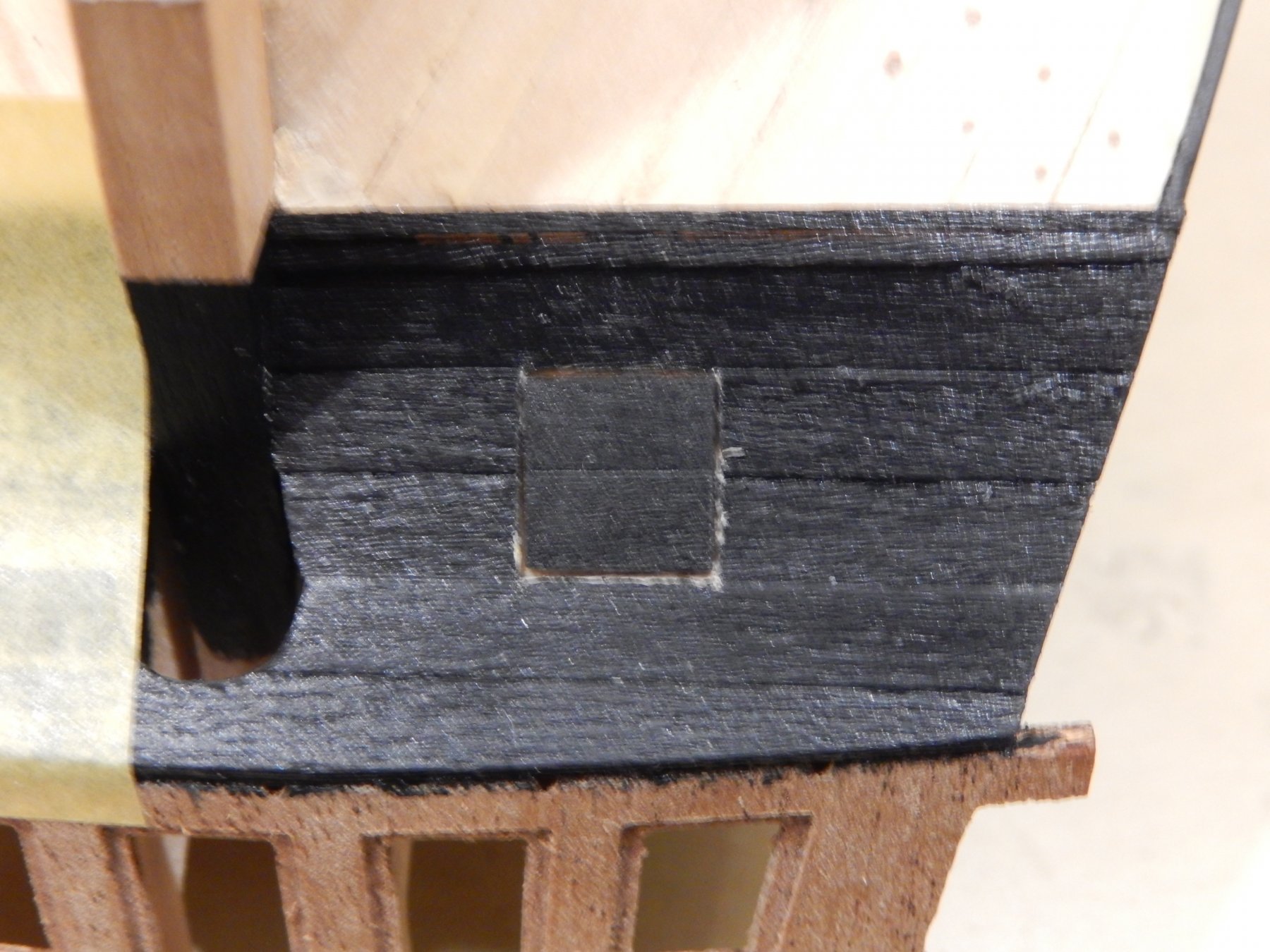
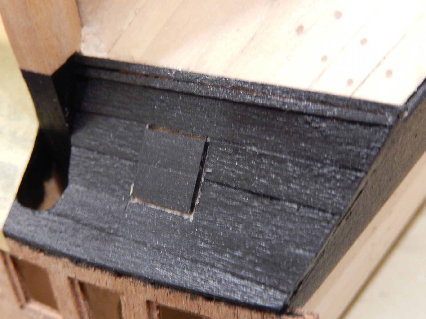
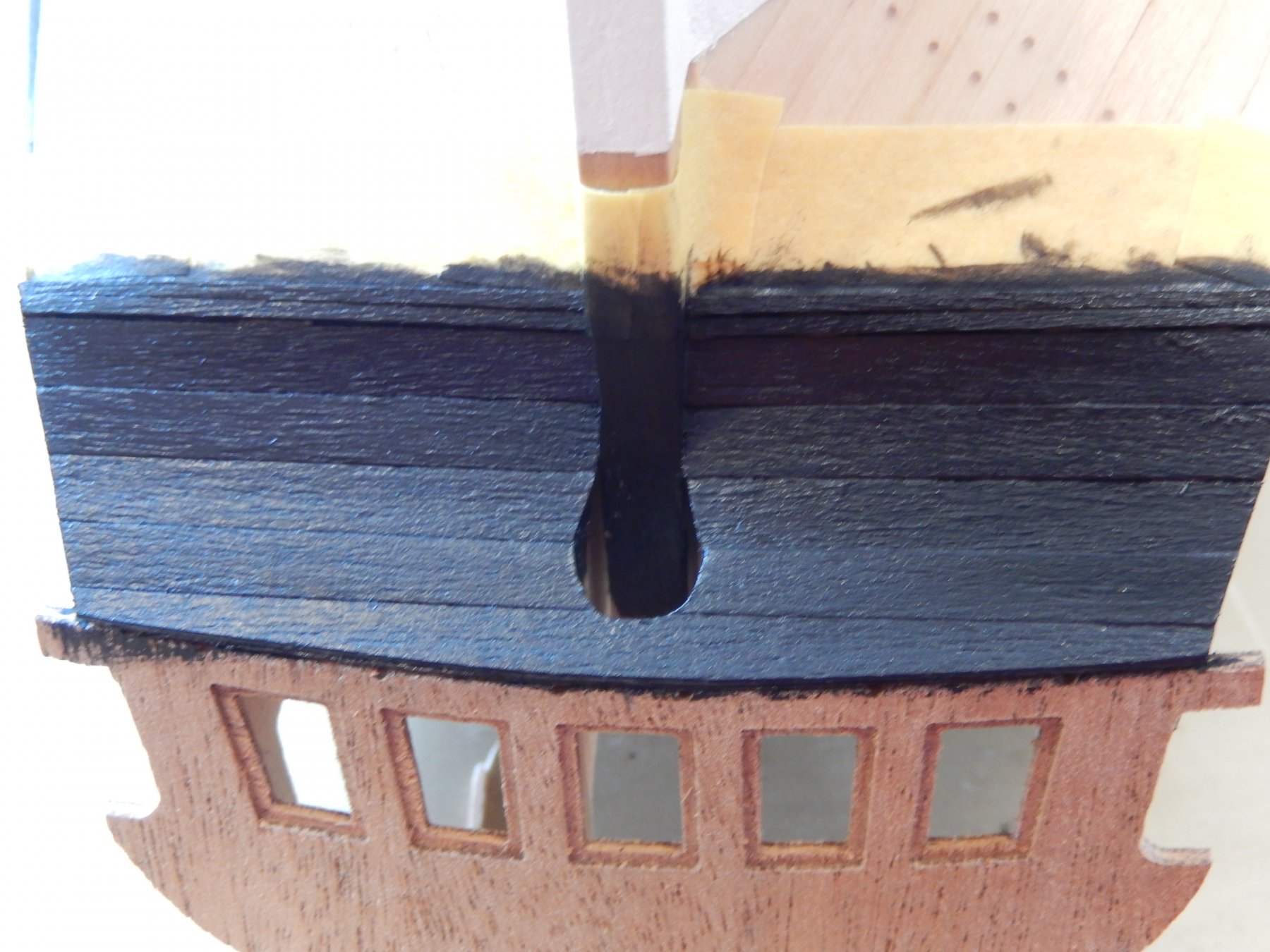
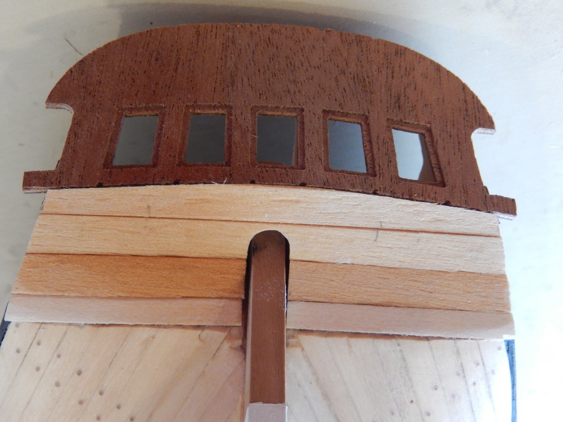
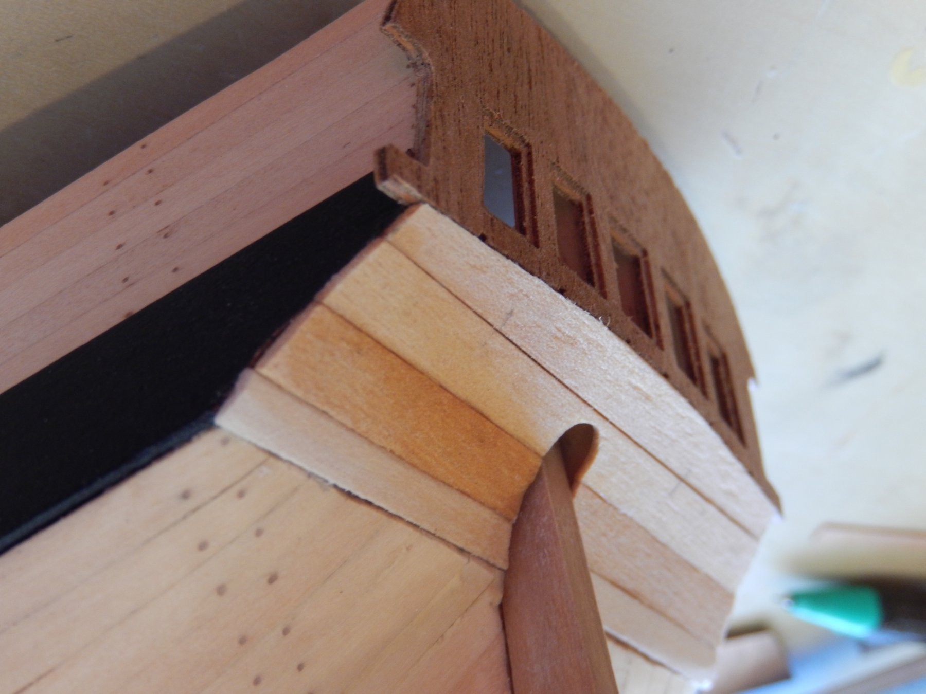
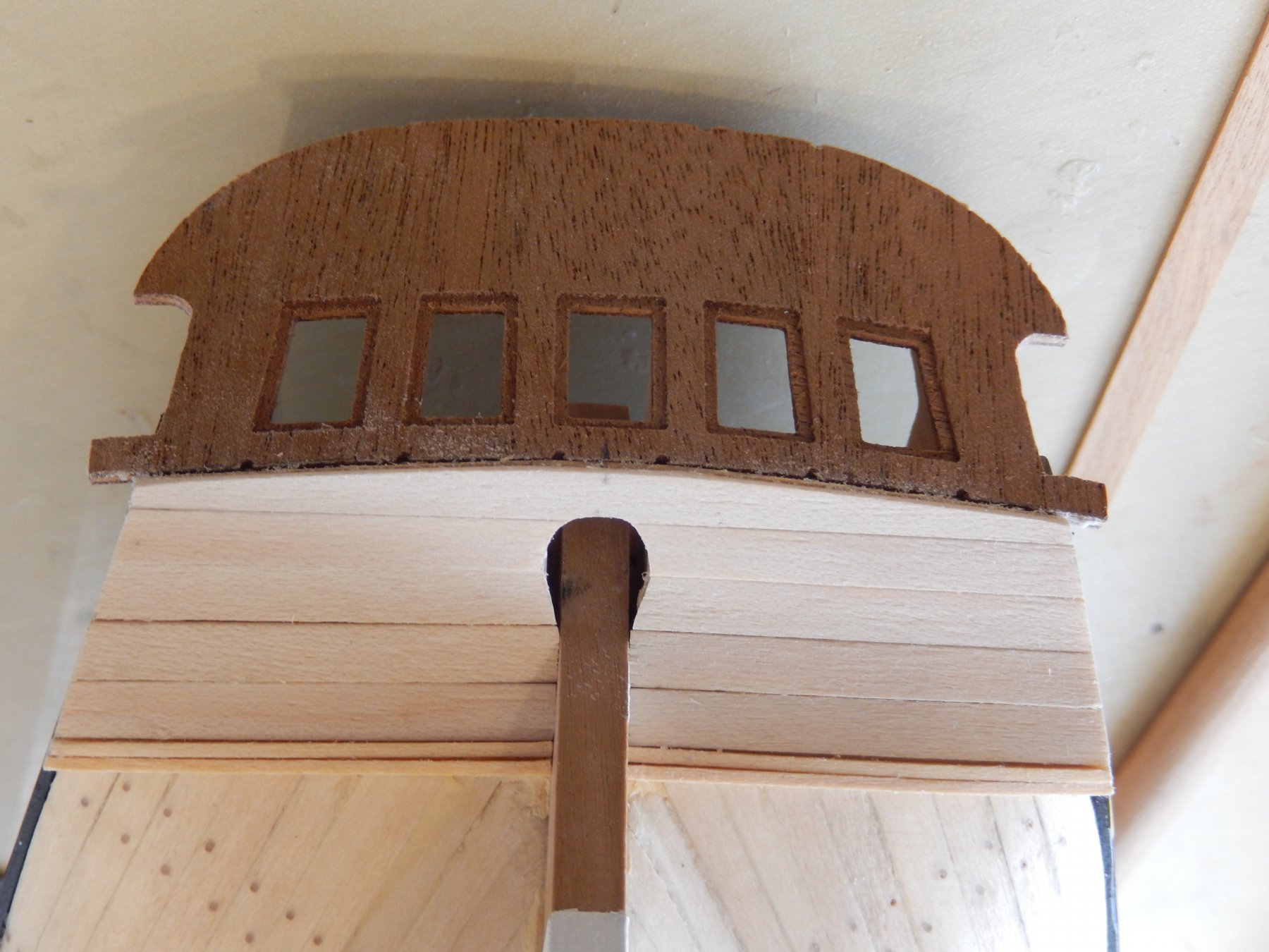
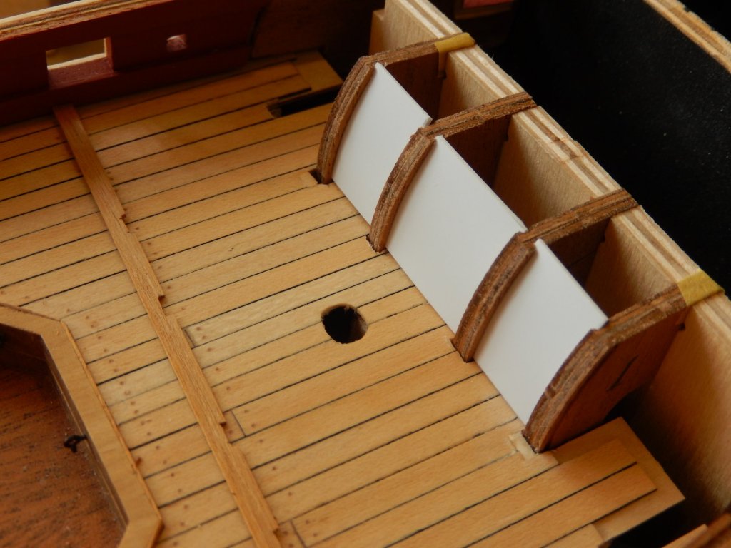
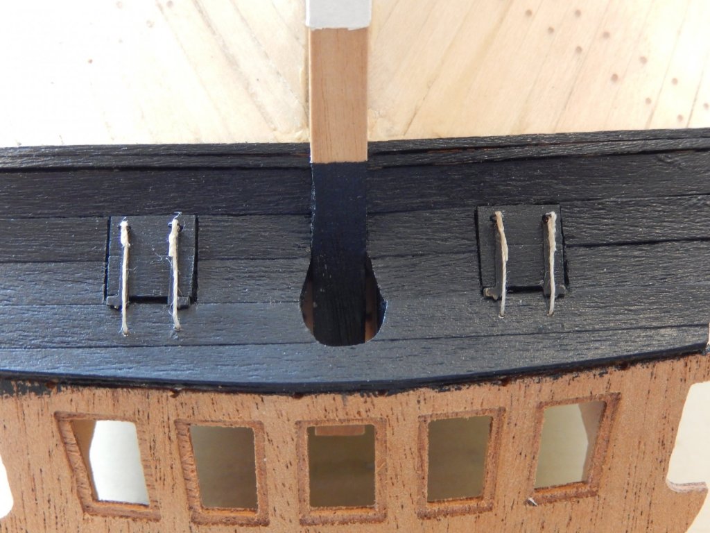
When I dry-fitted the bulkhead it became apparent that the grooves for the side screens were out by about 1mm at the bottom and 2mm at the top. It was not good news. The error stemmed primarily from incorrectly installing the bulwark pattern. Here is my solution to the problem. First a groove was cut in the appropriate position. The drill bits from the dentist have proved invaluable. A piece of timber was cut to shape and glued in place in front of, and behind the groove. This gave a far deeper groove for the screen and will, I hope make it easier to fit. The grooves in the supports a very shallow. ... and here is the result. At the moment the repairs only have one coat of paint and both need some further touching up, but it hasn't turned out too badly. The photos exaggerate the roughness of the job, but it will better once complete. Alan: I will try to get hold of a copy of the Kighorn (sp?) article. Thanks for taking the trouble. As an experiment I have painted one of the screens Admiralty paints French blue and another Tamiya mid blue. The Tamiya covered in one coat and looks quite good. The Admiralty paint has not covered well and may need at least two more coats. I will post some photos when finished, but the French blue is, to my eye rather garish.


- 421 replies
-
- 8
-

-
- caldercraft
- granado
- (and 1 more)
-
Hi Alan - I think it's likely you are right. The curves of the screens do not appear to be functional - particularly the curved door. However at this stage I almost feel obliged to finish the damn thing consistent with the plans provided in the Anatomy of a Ship, and I can only presume they are accurate. In doing so, I have discovered that an error I made earlier has come back to bite me. It has taken me some time to correct it - and I am still not sure yet that I have succeeded. Photos to come. I have already said that I will probably not use the transfers of the illustrations on the screens. They look rather toy-like, but I am not sure how plain (light) blue screens alone will look either. Perhaps a glass of wine will help.
-
Hi Peter It's all a bit confusing - but have a look at the photo on page 35. I think that gives me an out. The horizontal beam under the curved supports only needs to be a fraction deeper than that shown in the photo to cover my errors. Replacing the planks doesn't bear thinking about. All the best Bob
- 421 replies
-
- 2
-
-
- caldercraft
- granado
- (and 1 more)
-
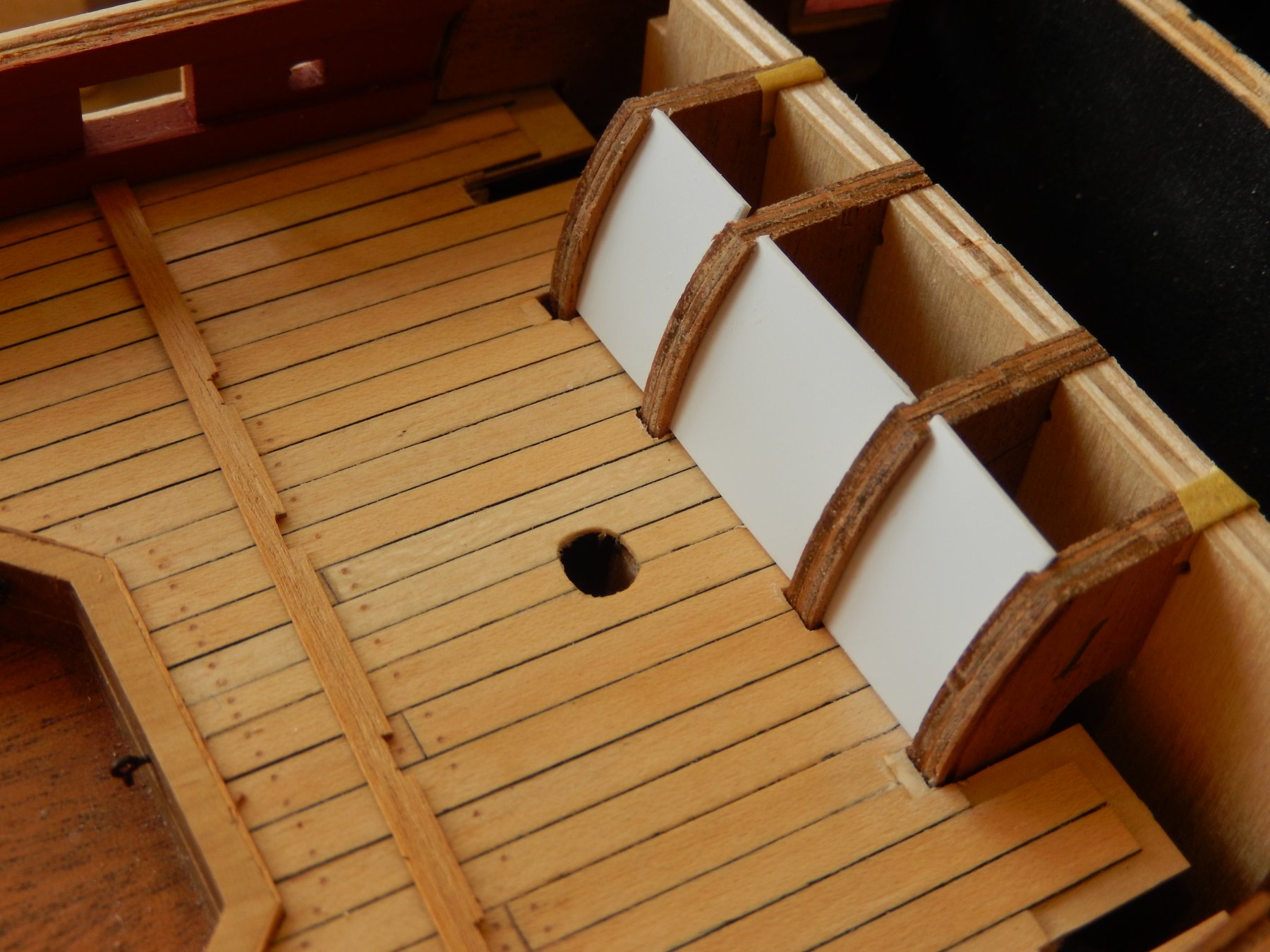
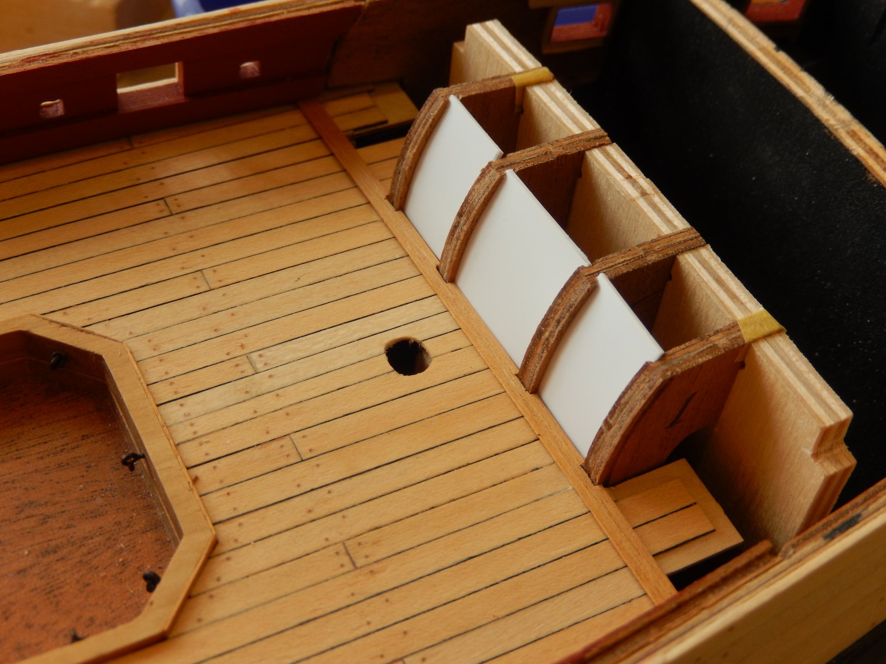
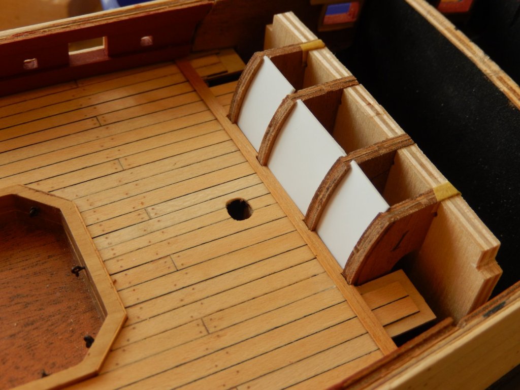
Progress is slow. The quarterdeck bulkhead is proving to be quite difficult and time-consuming. Everything seems to fit now, but I have made a mess of two of the cutouts for the supports. I have left the repairs as is for the time being, (see the first photo) but I think I can do a better job. If all else fails I will fudge it - cover the whole lot as shown in the second photo, though I would prefer some lighter coloured timber. Like Joe V I have used polystyrene for the panels rather than the ply supplied in the kit. They will be painted light blue, but I will probably not use the transfers of the drum etc. but may have go at painting the pictures. If that doesn't work (likely) I will probably leave them simply painted. Every thing shown below is dry-fitted. The windlass has another coat of poly on it and the ends are now painted. I will forget about painting/staining it.
- 421 replies
-
- 9
-
-
- caldercraft
- granado
- (and 1 more)
-
Thanks Sam. I think I will go with another coat of the polyurethane. The stain/paint look too artificial.
-
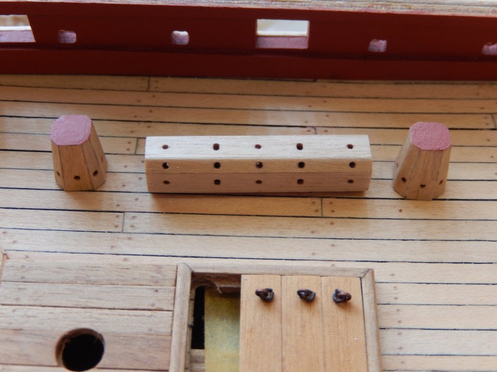
I have now put the windlass together, and a very fiddly job it was. It is shown with a coat of polyurethane. I have experimented with walnut stain and Admiralty walnut paint. The paint gives a slightly better finish, though it is still not all that accurate a colour. At this stage I am undecided, but am inclined to put another coat of poly on it and leave it as is. Comments are welcome.

- 421 replies
-
- 10
-
-
- caldercraft
- granado
- (and 1 more)
-
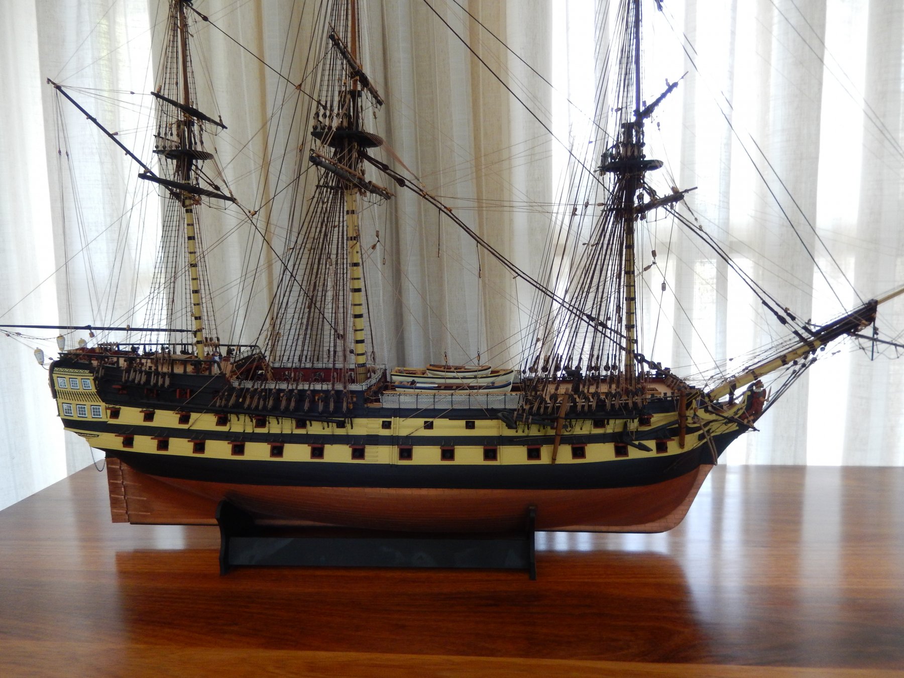
Thanks mark. I'm afraid I was rather shortsighted about what to do with the thing once it was finished. I will probably have a case built, but at the moment I'm not sure how best to fit it in with the table.
-
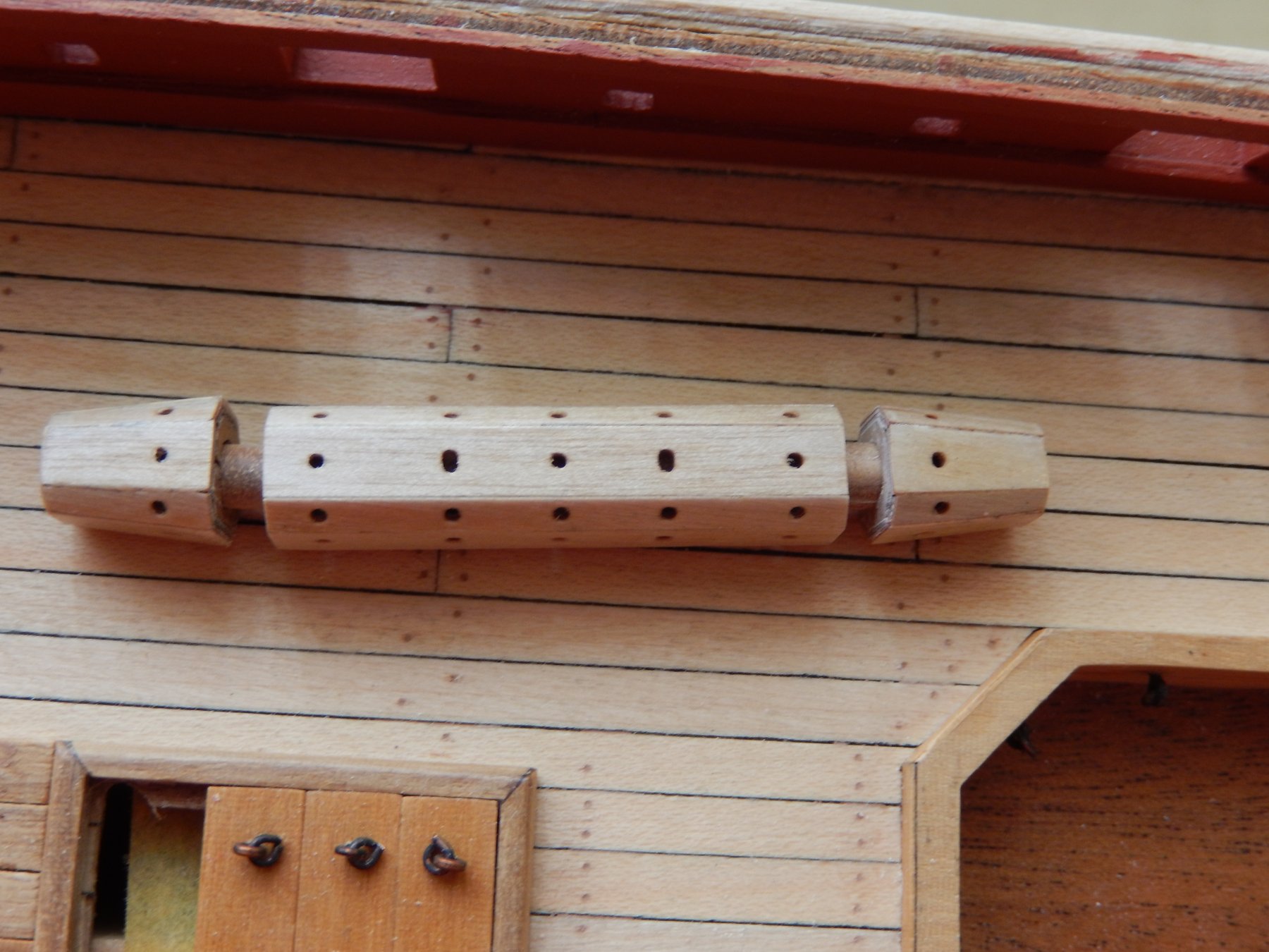
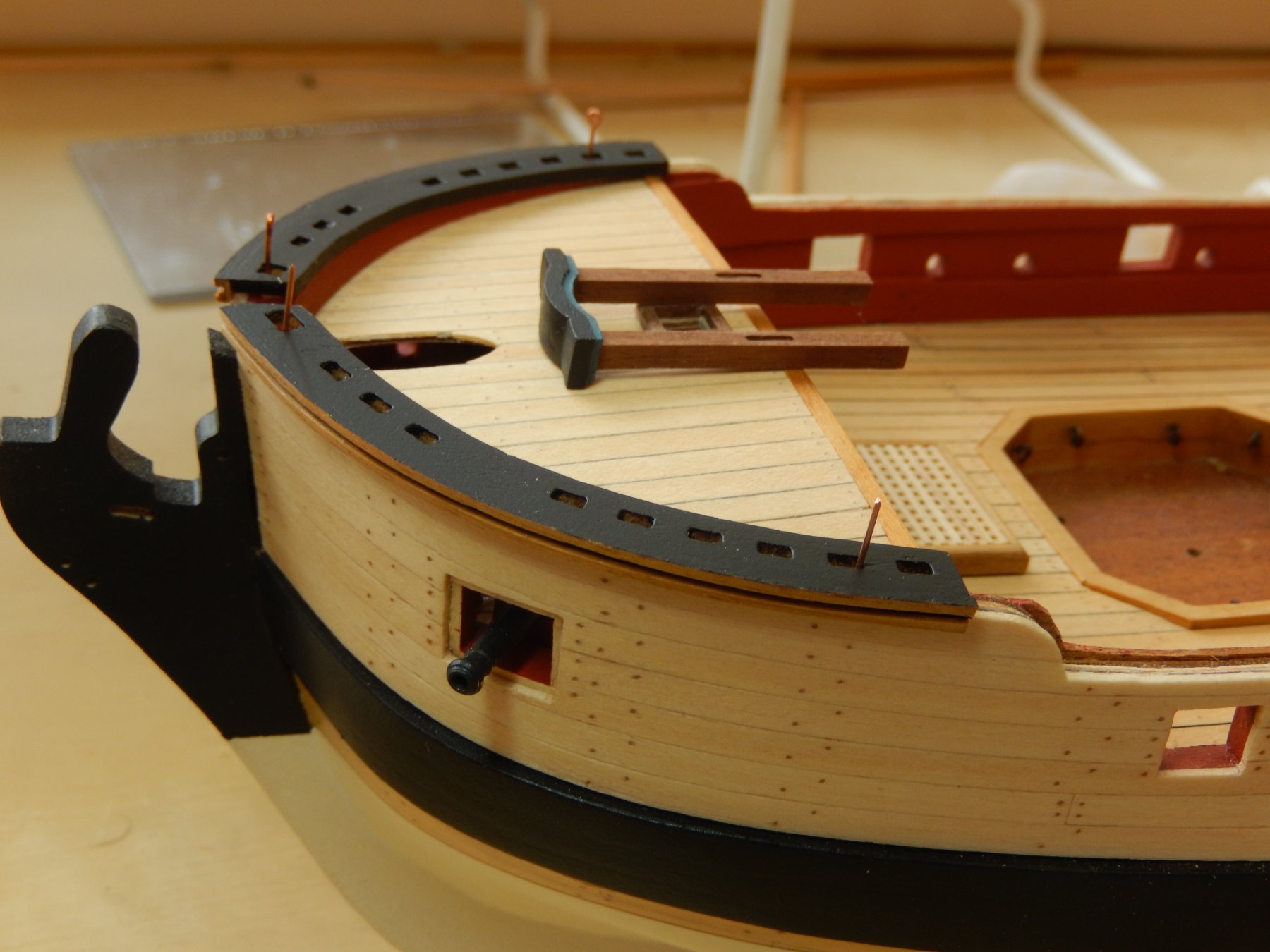
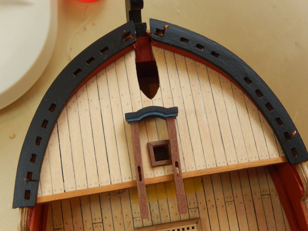
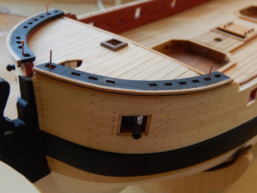
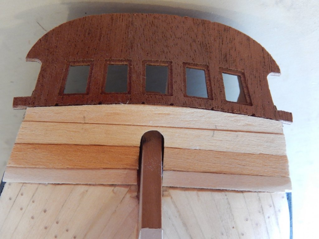
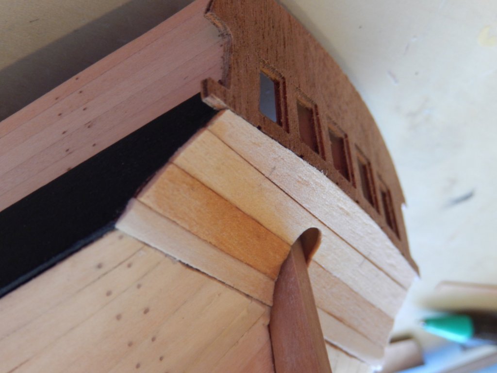
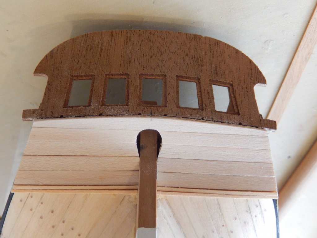
Joy. The missing parts showed up today. The service from Cornwall Model Boats was excellent. Progress on Granado has been slow. I had to put a few finishing touches on Vanguard which is now FINISHED.😁 The fore castle capping on Granado is now done, and in the end proved more difficult than I expected. It is only dry-fitted in the photos and will remain that way until all the capping is ready to install. It came out reasonably well - fortunately most of its shortcomings will be obscured by other detail. The top of the belfry has been painted - otherwise the edges of the plywood trim would be seen. I have painted the lower edges Tamiya mid-blue. I tried Admiralty Paints French blue, but the colour seemed to me to be too strong. I will probably use the lighter blue on the rest of the model.

- 421 replies
-
- 8
-
-
- caldercraft
- granado
- (and 1 more)
-
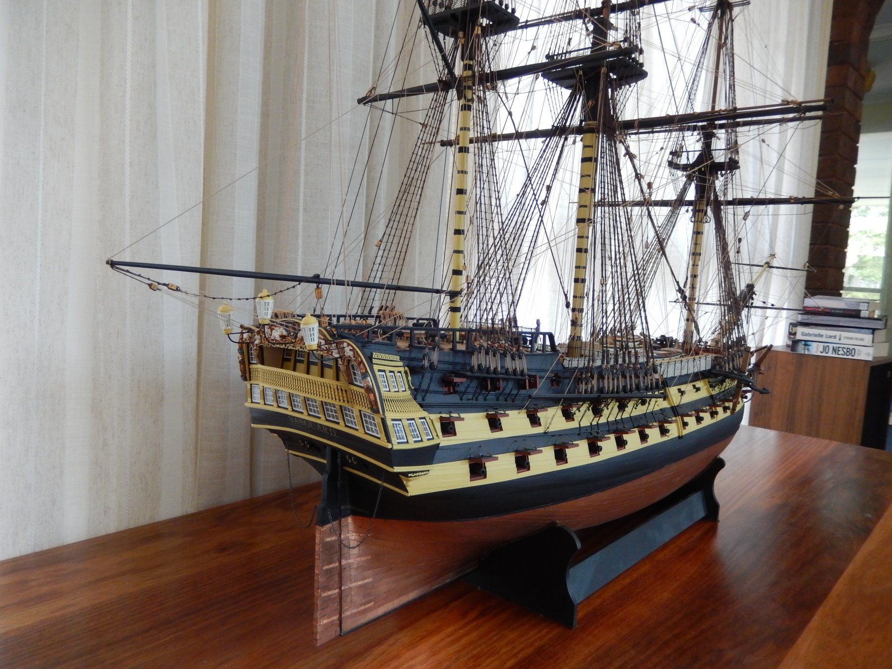
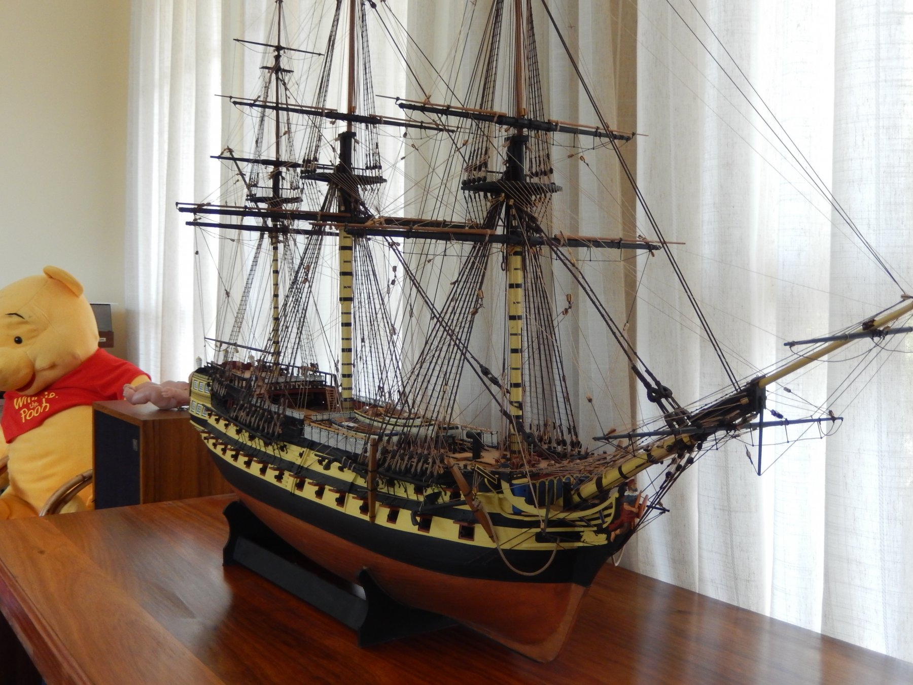
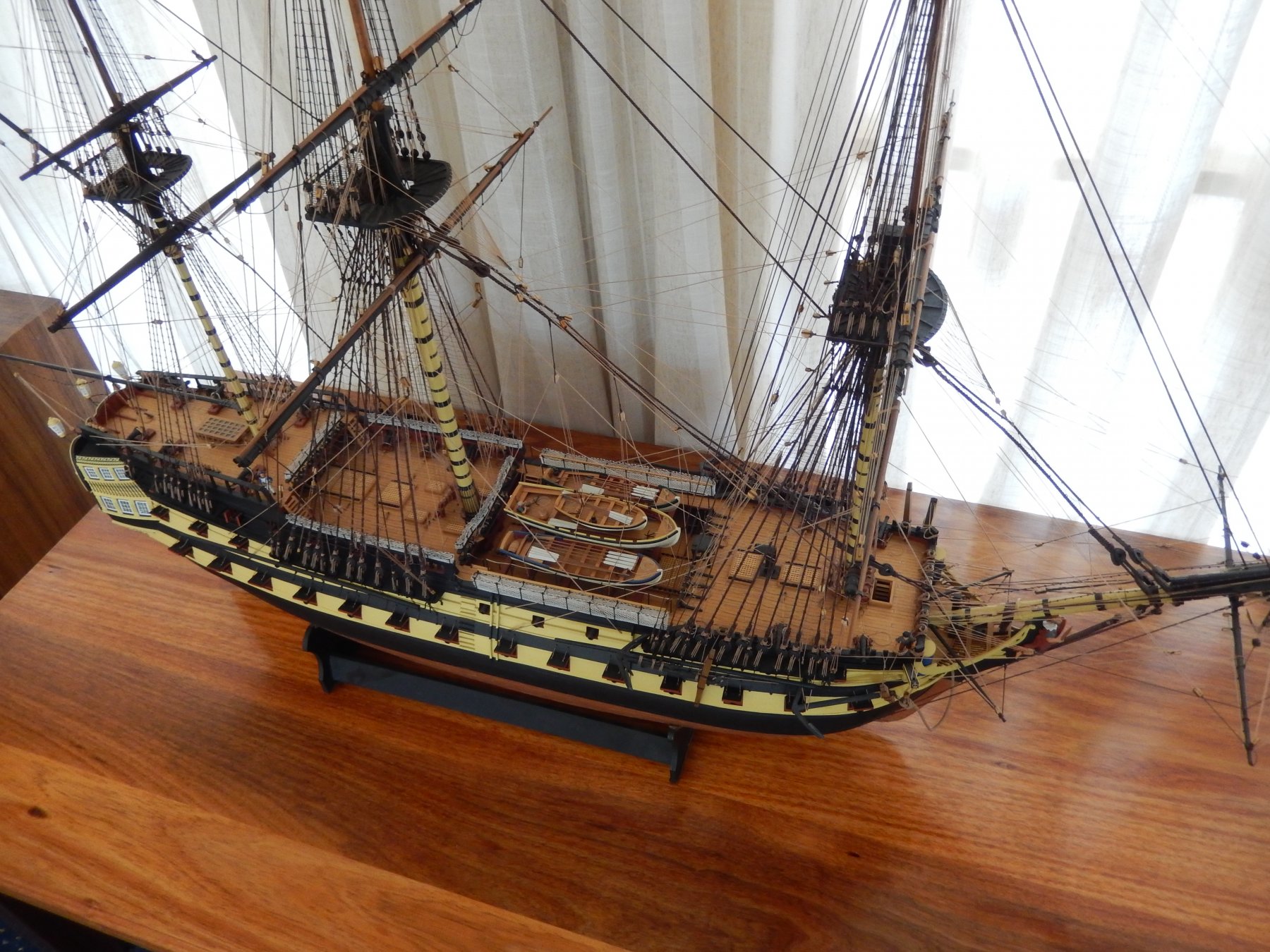
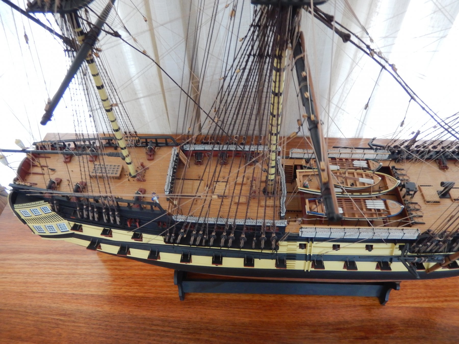
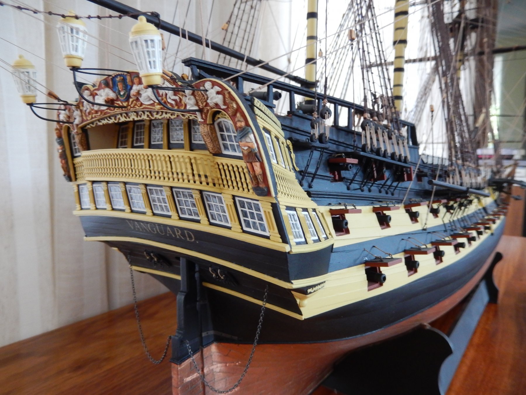
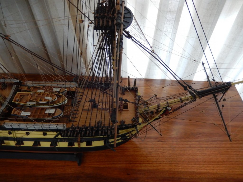
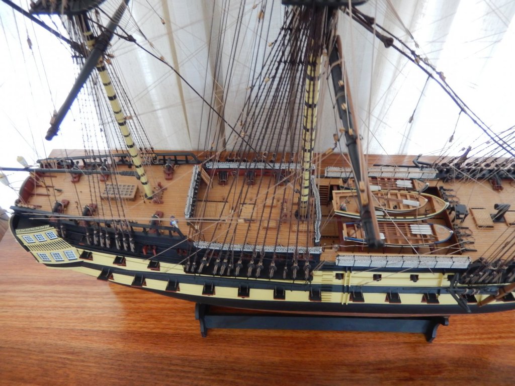
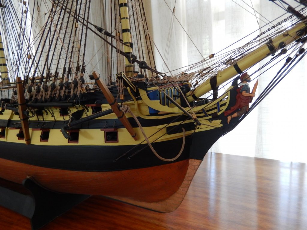
Vanguard is finished- after five or so years. I have had a beautiful Tasmanian blackwood table made to accommodate it and the result is quite pleasing. I am now recovering from my near heart attack while carrying it down the stairs. Here are the final photos. I see Winnie the Pooh in the background.


- 949 replies
-
- 19
-
-
Things are delayed until the missing parts show up. Until then I will do some of the fittings. Before that however I will try to complete the forecastle capping - though only dry fit it. This is how it's turned out so far. I have stuck my molding onto it and have now repainted the top, including the top of the molding (not shown). I am now waiting for the paint to dry. Photos of this later.
- 421 replies
-
- 9
-
-
- caldercraft
- granado
- (and 1 more)
-
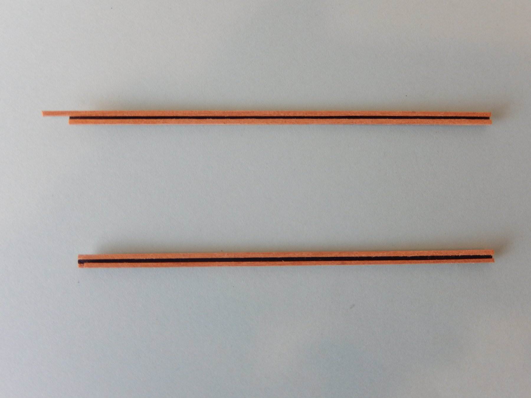
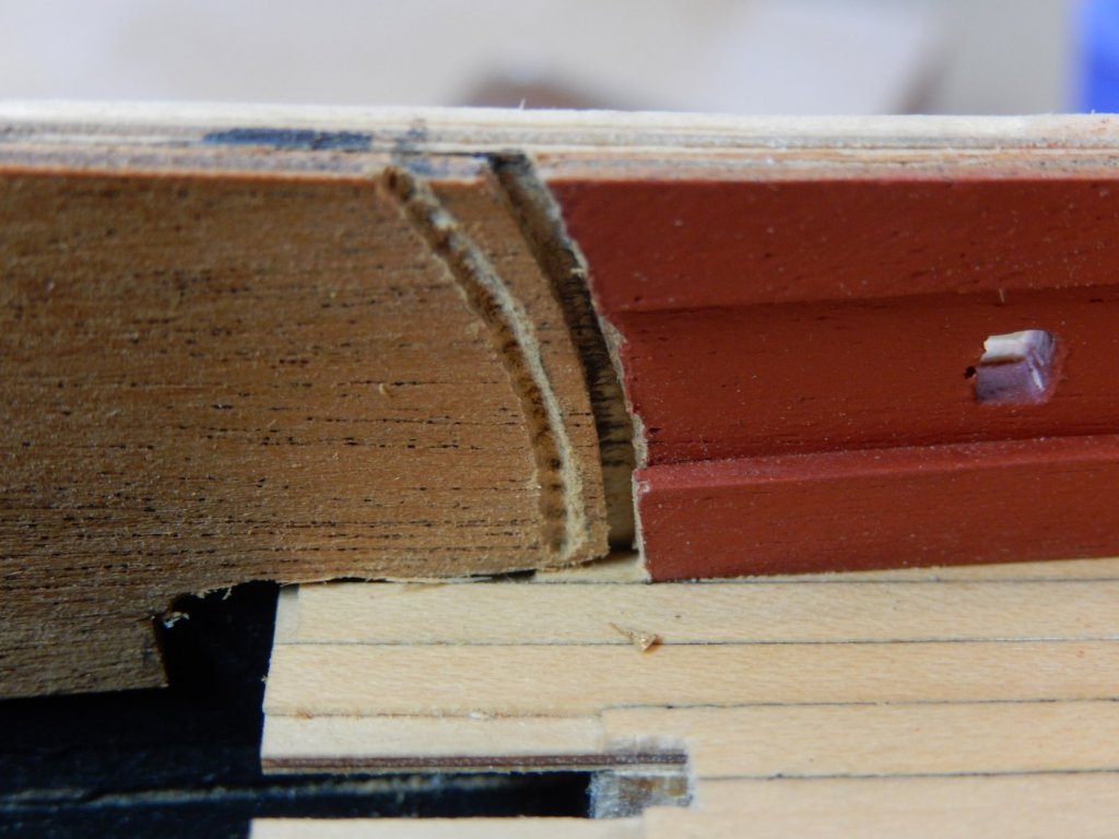
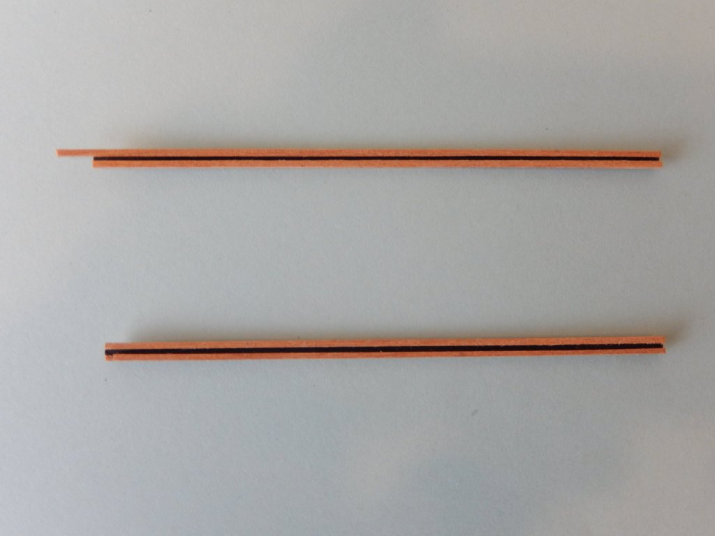
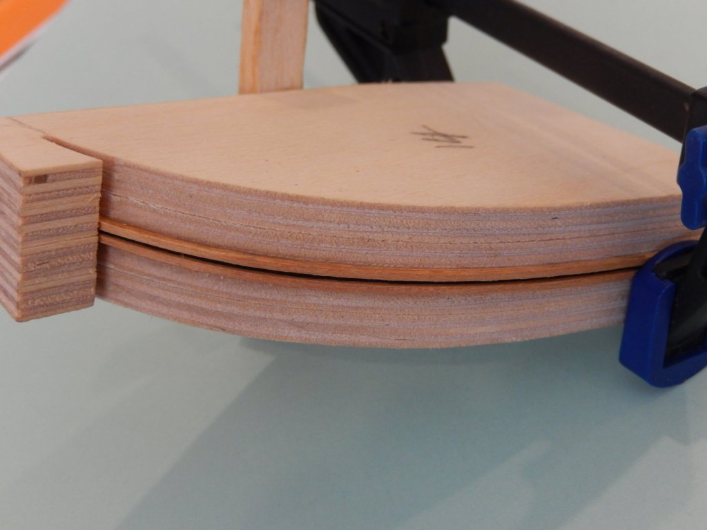
Having looked at Joe V's excellent Granado I tried to duplicate the trim on his forecastle capping. His method entailed scribing a channel down the centre of a piece of a (roughly) 2.5x1mm timber strip. My channel looked like a dog's breakfast and so I looked for an alternative. I then took a piece of 2x0.5mm strip, painted down its centre, then glued pieces of 1x1mm strip on each side. Here are the results. As you will see, the gaps are slightly different, but at 'lifesize' the difference is scarcely noticeable. Nevertheless I will make up another one, then choose the best two of the three. I thought bending may be a problem, but it turned out quite well.
- 421 replies
-
- 6
-
-
- caldercraft
- granado
- (and 1 more)
-
While the shape is shown on the parts list, the dimensions aren't. If the sheet of ply were available to provide a pattern it would be easy, as it's not .... The dimensions being out by even a little is not likely to end well.
-
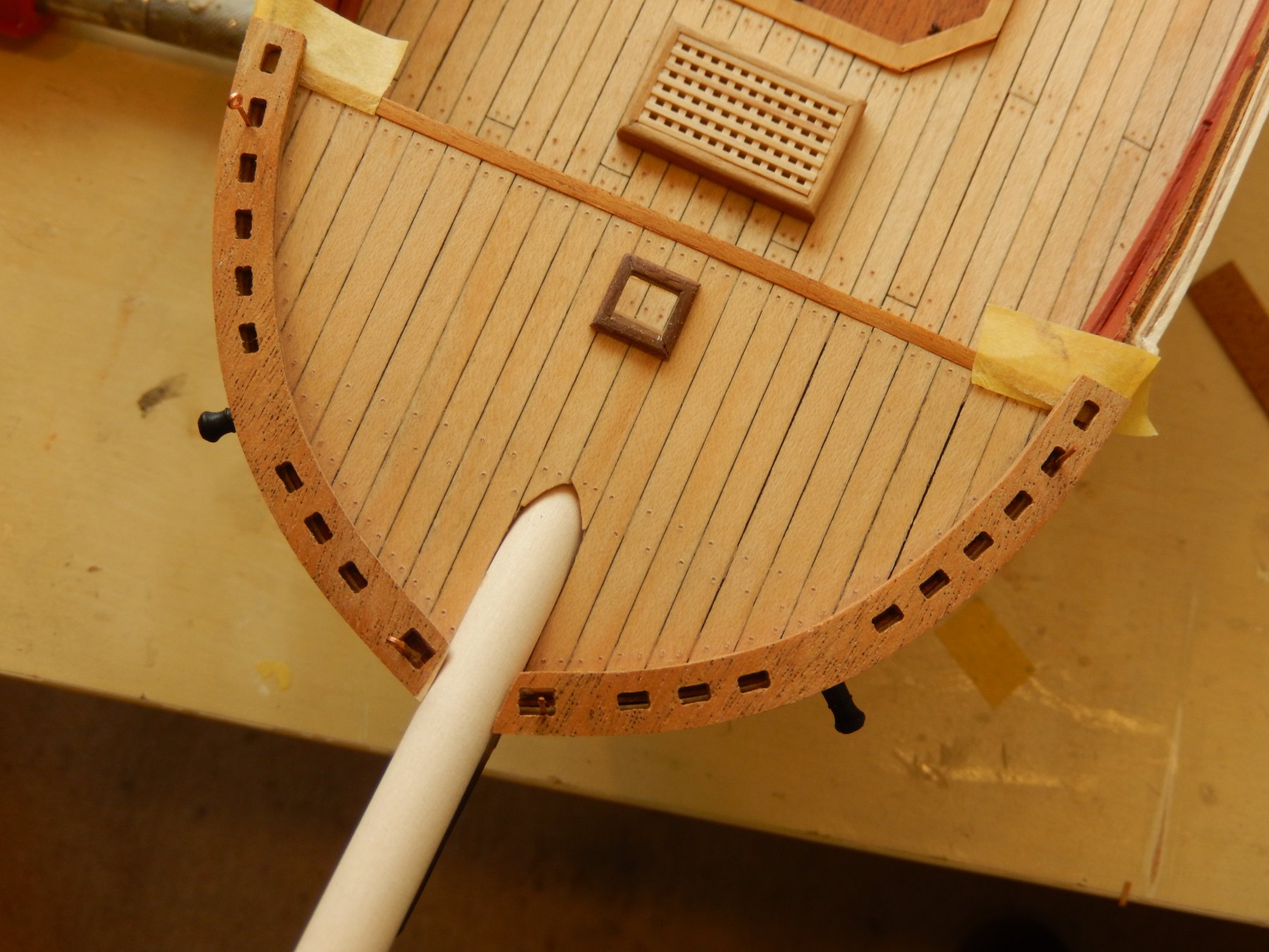
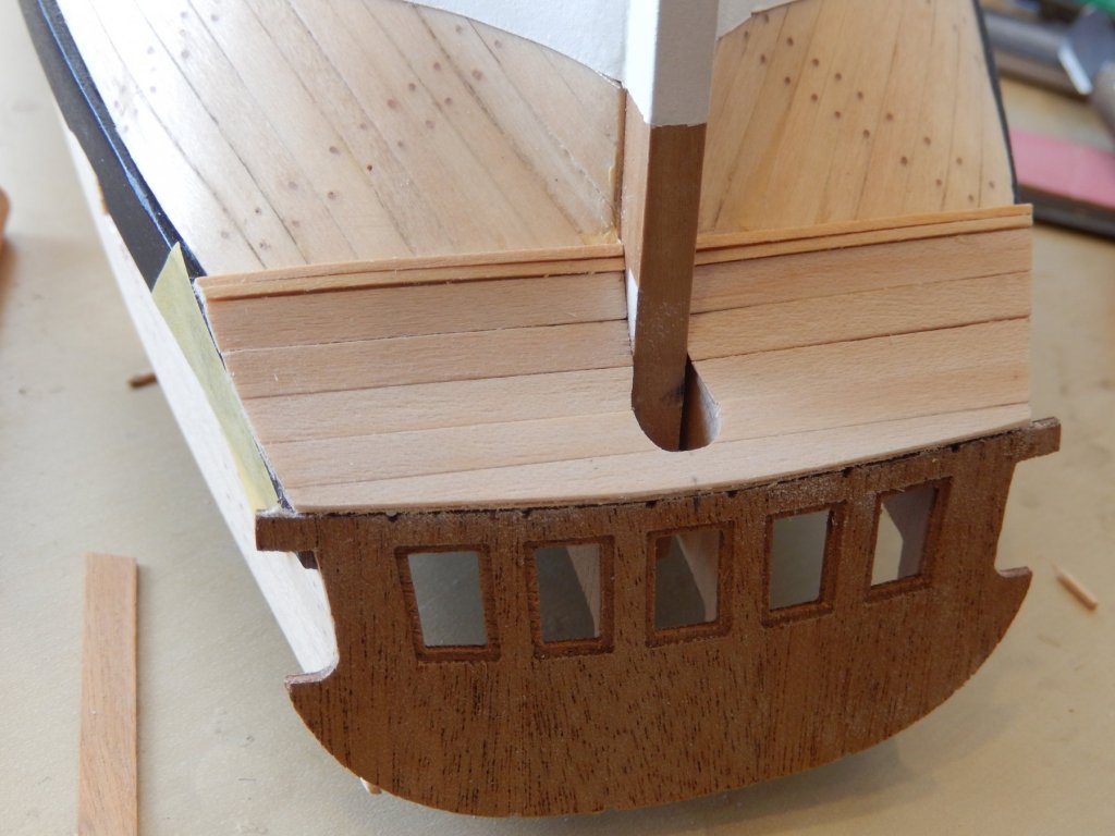
A belated thank you Kevin for the video - very useful I have done some work on the forecastle capping. Unfortunately I have discovered that the sheet with the quarterdeck curved pillars is missing. I guess I should have checked the contents of the box when I first received it, but is a bit of a pain. Until I receive them I can't put on the main capping and of course the quarter deck is in limbo. Here is some progress. Fortunately the capping fitted the curvature of the bow perfectly. At least something has gone right.

- 421 replies
-
- 6
-
-
- caldercraft
- granado
- (and 1 more)
-
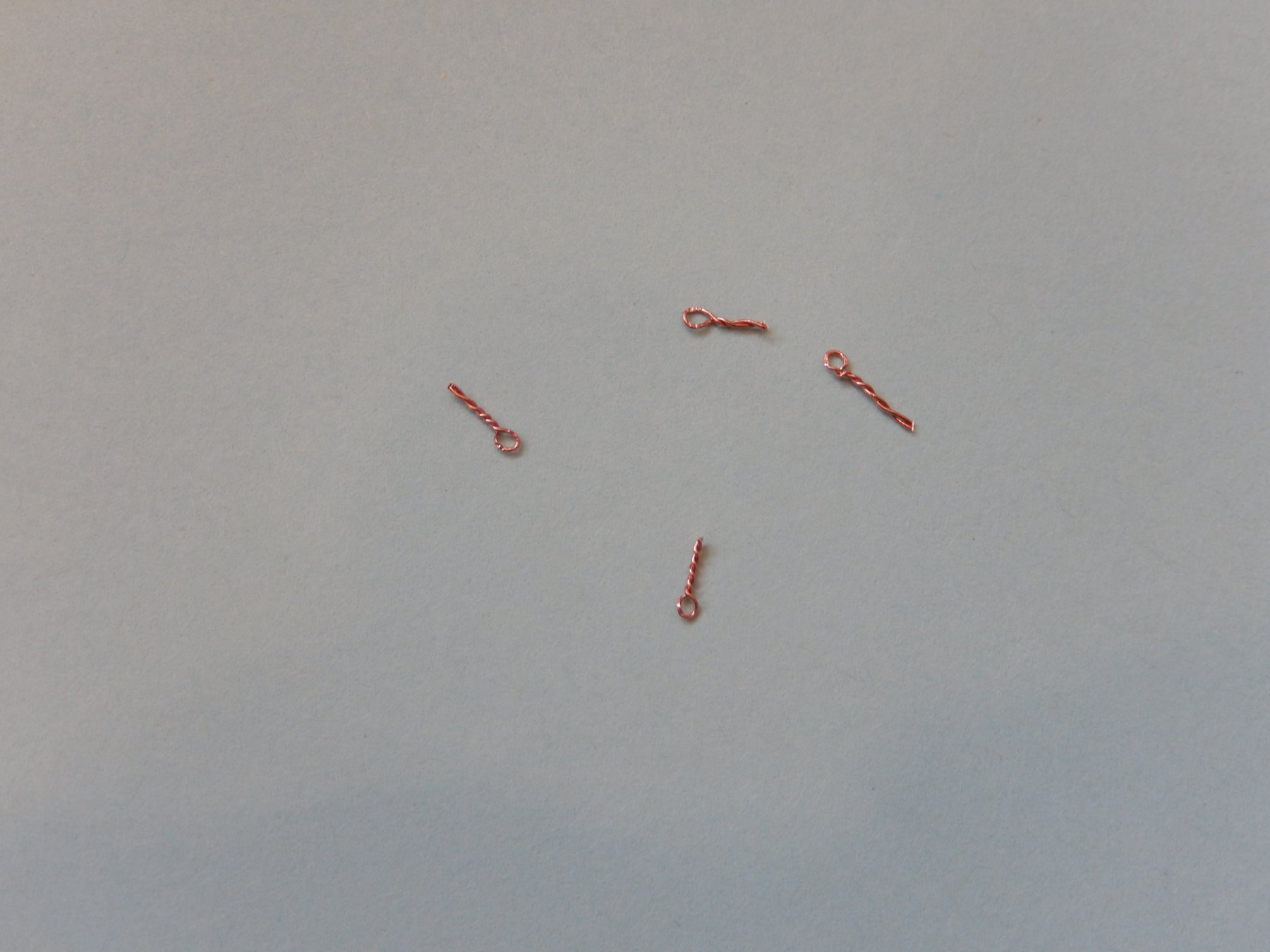
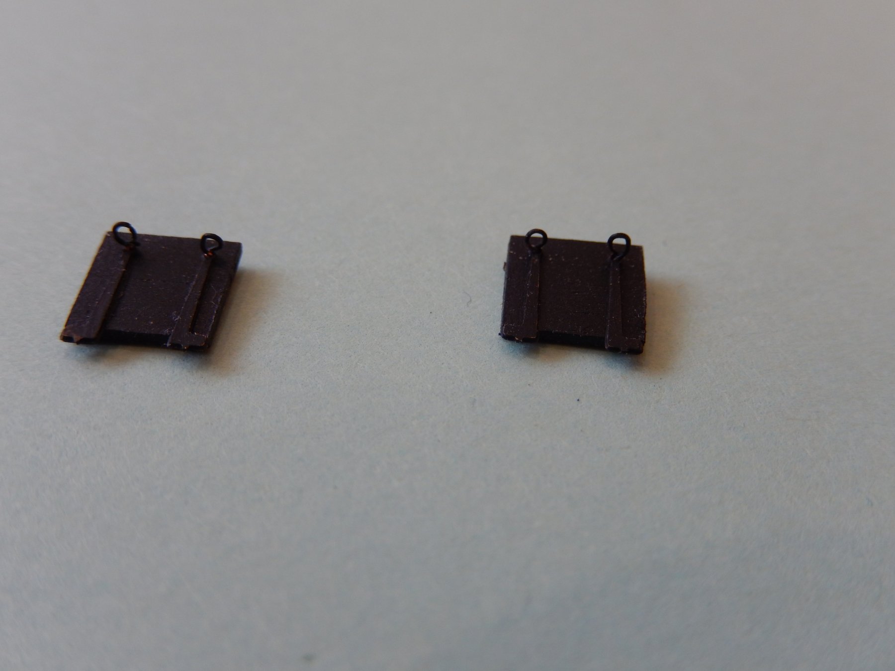
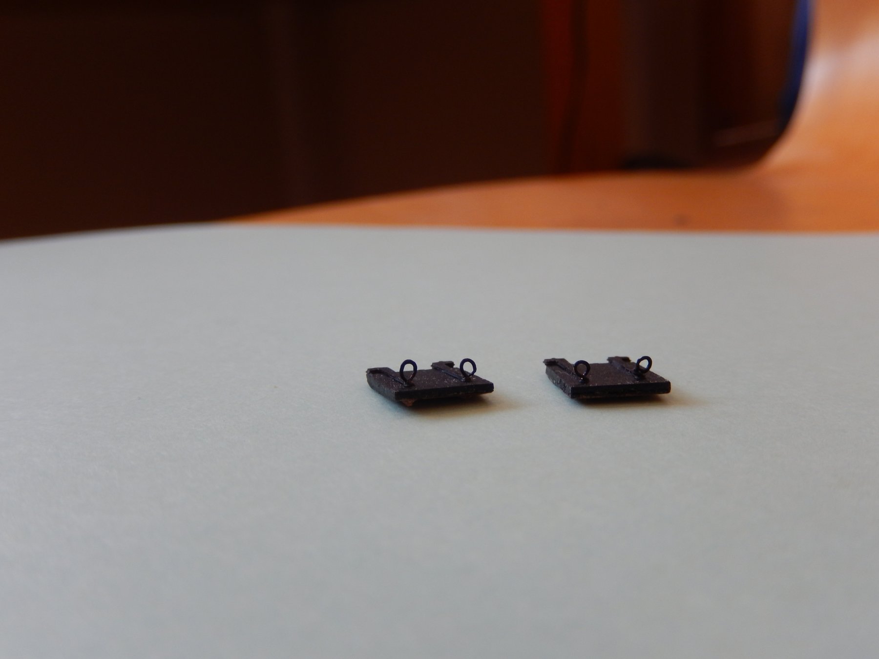
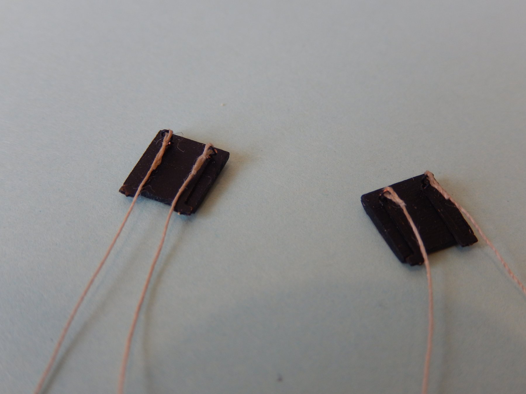
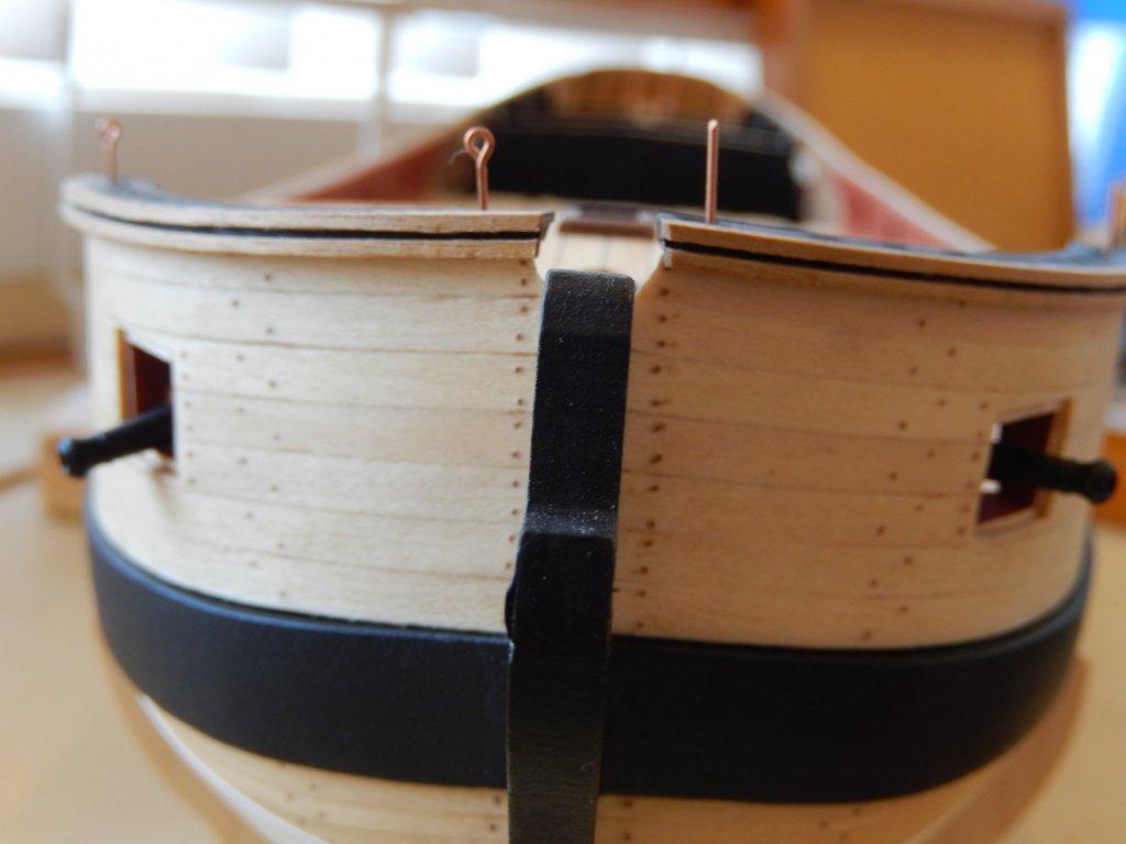
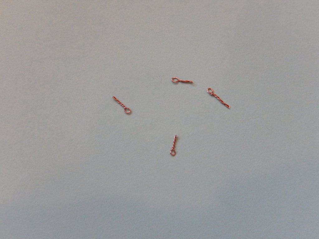
The lids are now fixed. I'm reasonably happy with the result. In the instructions there appears to be no mention of the ropes (lanyards?) supporting them. They are, however, shown in the illustrations on the Jotika website. To put them on requires eyes that are far smaller than the eyelets that are commercially available. I have used a strand of fine copper electrical wire to make up the following eyelets. Here they are installed and painted Finally - I have now turned the model right-way up. I was then able to make the ropes taught. To my pleasant surprise the guns remained in place.


- 421 replies
-
- 6
-
-
- caldercraft
- granado
- (and 1 more)
-
The Mary Rose museum is everything Rob Durant suggests. My wife thought it was wonderful and she is not a boating person. Me? Of its type, it is the best I have seen. Very, very highly recommended.
- 421 replies
-
- 2
-
-
- caldercraft
- granado
- (and 1 more)
-
Thanks for your good wishes Rob. I couldn't resist. I have had a very close look at the Anatomy of a Ship. The lids are NOT quite flush with the counter. So here is my solution and the process of taking off a layer of planking was rather fraught. At the moment the lid is dry-fitted and the photos exaggerate the faults. Obviously it needs to be touched up, but once painted, should look quite acceptable. All I have to do is a similar job on the other side - but that really will have to wait.


- 421 replies
-
- 9
-
-
- caldercraft
- granado
- (and 1 more)
-
Thanks GrandpaPhil as one grandpa to another. Peter: good to hear from you. I don't know about withdrawal - it's more like a hangover. I am finally having a table built for it so I can get it out of my work room. Back to the Granado: unfortunately I think you are right. If I stuck the damn things on as is, it would niggle at me. It will have to wait however. I will be going away for about four weeks next Thursday and there are the usual jobs to be done beforehand. One thing to which I shall look forward is a visit to the Mary Rose museum in Portsmouth. The last time we were there it was closed while all the preservative sprays etc. were switched off.
- 421 replies
-
- 1
-
-
- caldercraft
- granado
- (and 1 more)
-
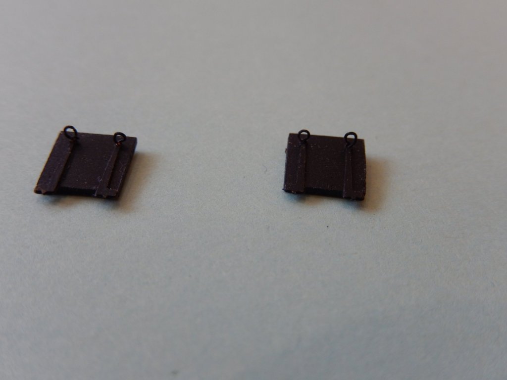
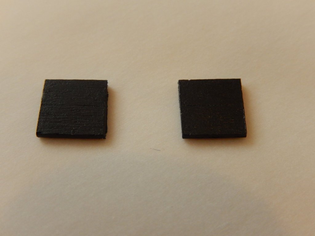
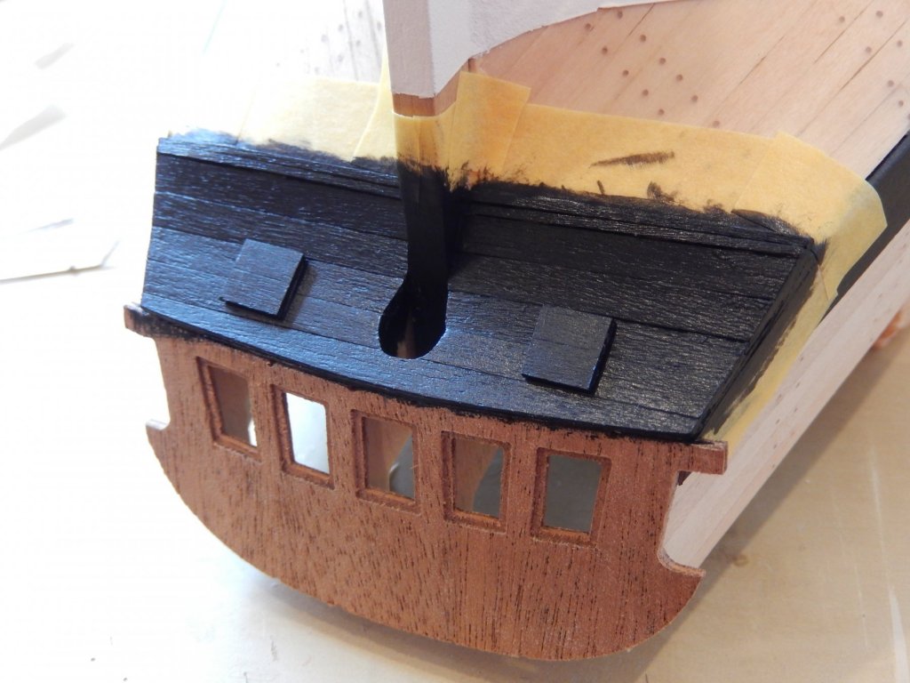
There are now 3 coats of paint on the stern counter. Despite appearances in the photos, it doesn't look too bad in the flesh. Nothing has yet been touched up. I will sand it back a little to improve the finish, then put 2 coats of polyurethane on it. As an experiment I have made a couple of stern vents. The instructions suggest that to give an appearance of the vents, scribing their outline on the counter which I would prefer not to do. Here is the painted stern counter. The vents. They are less than 1mm thick, but I think I can make them fractionally thinner. The vents simply resting on the counter. The shadows exaggerate their thickness. I am undecided whether to go ahead - opinions are welcome.

- 421 replies
-
- 9
-
-
- caldercraft
- granado
- (and 1 more)
-
Oh .... I forgot. The hole provided for the rudder on the stern counter ply is too small and the wrong shape.
-
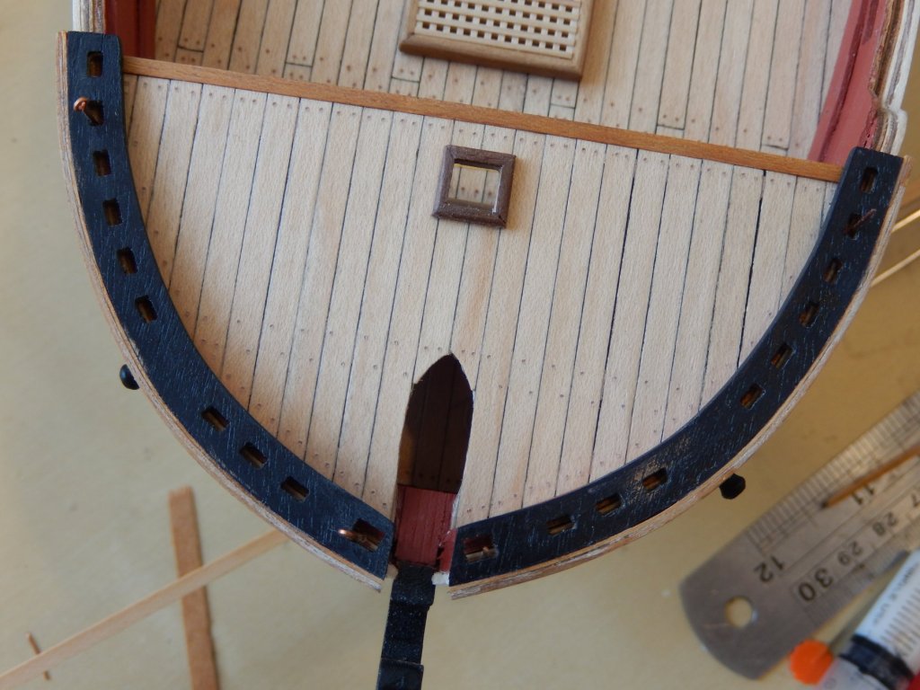
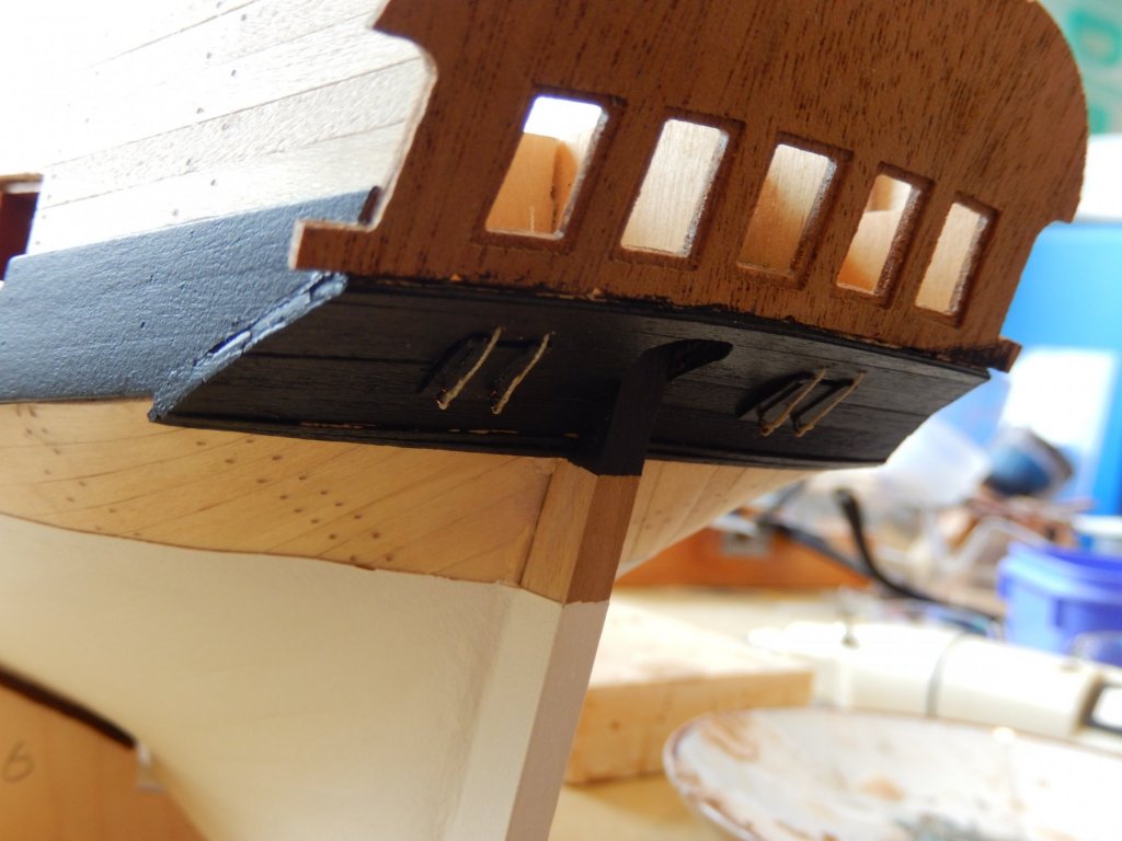
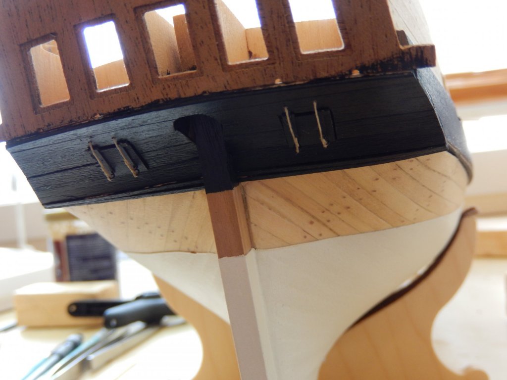
The instructions suggest the next steps are to attach the stern fascia and counter. The fascia does not provide a problem: the stern counter certainly does. The only practical way of working on it requires the model to be turned upside down. Having installed the cannons for the chase ports - as suggested - this leaves the guns hanging from what has become the ceiling. I just hope the guns are still where I glued them when the thing is turned the right way. Lesson: do the stern THEN the fore deck. The second problem is with the walnut ply supplied as the base for the stern counter. Having given it the obligatory 30 minute soak in water and 2 days in a jig to bend it, it refused to be bent to shape. Fitting clamps to glue it to the hull proved impractical. I therefore scrapped it and simply used timber strip which proved to be relatively easy. Here are the results. The first three photos have been rotated. This, and the next photo show the first layer of planks. The last two show the planking complete.
- 421 replies
-
- 9
-
-
- caldercraft
- granado
- (and 1 more)
-
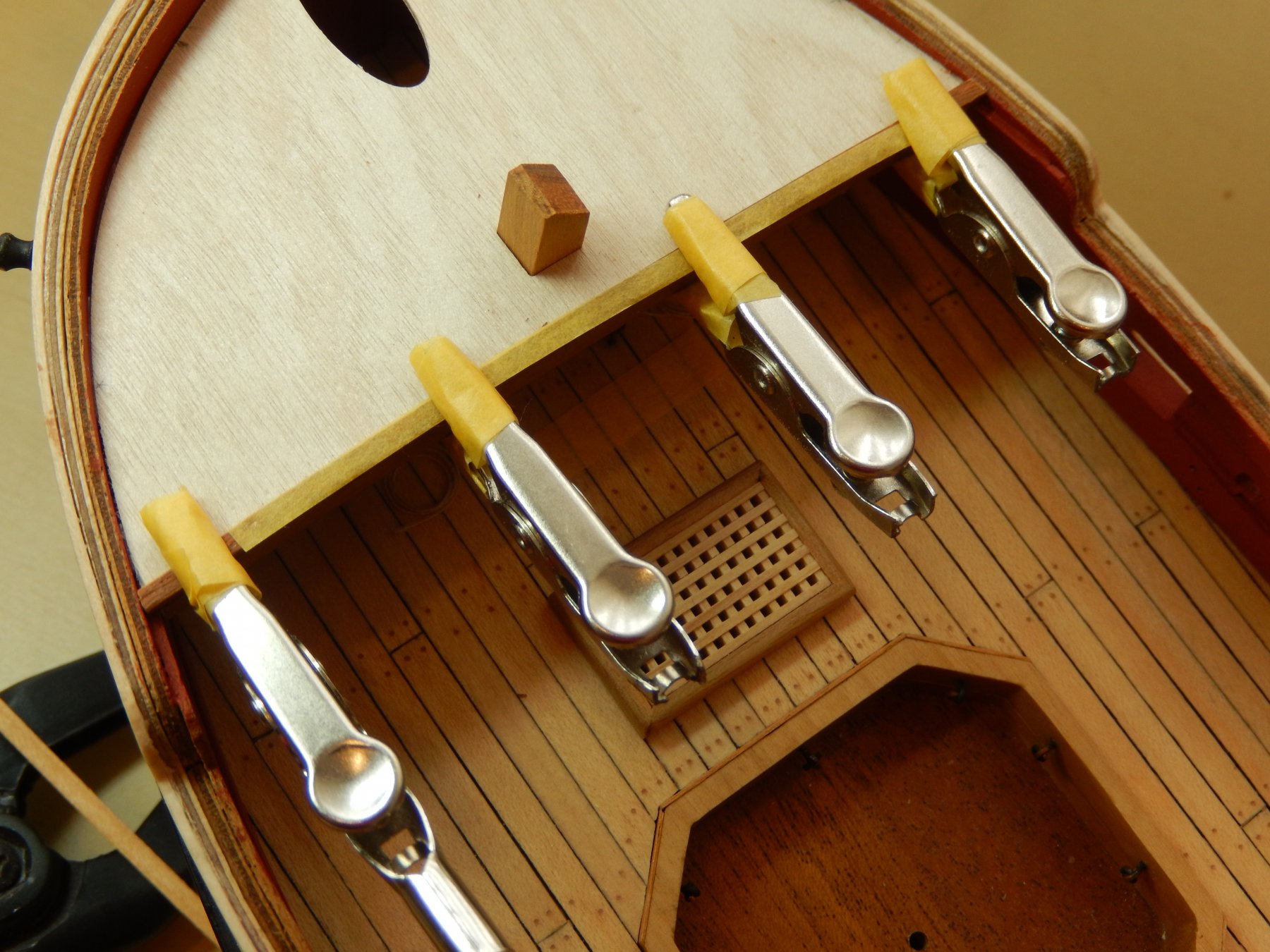
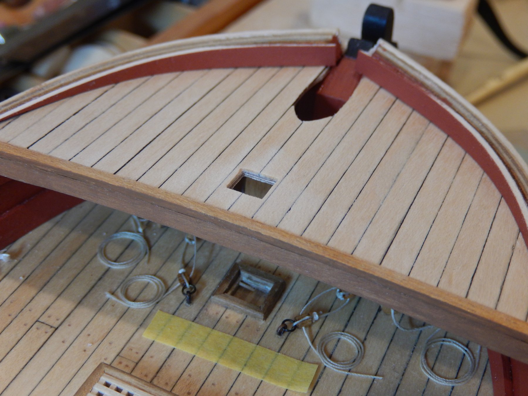
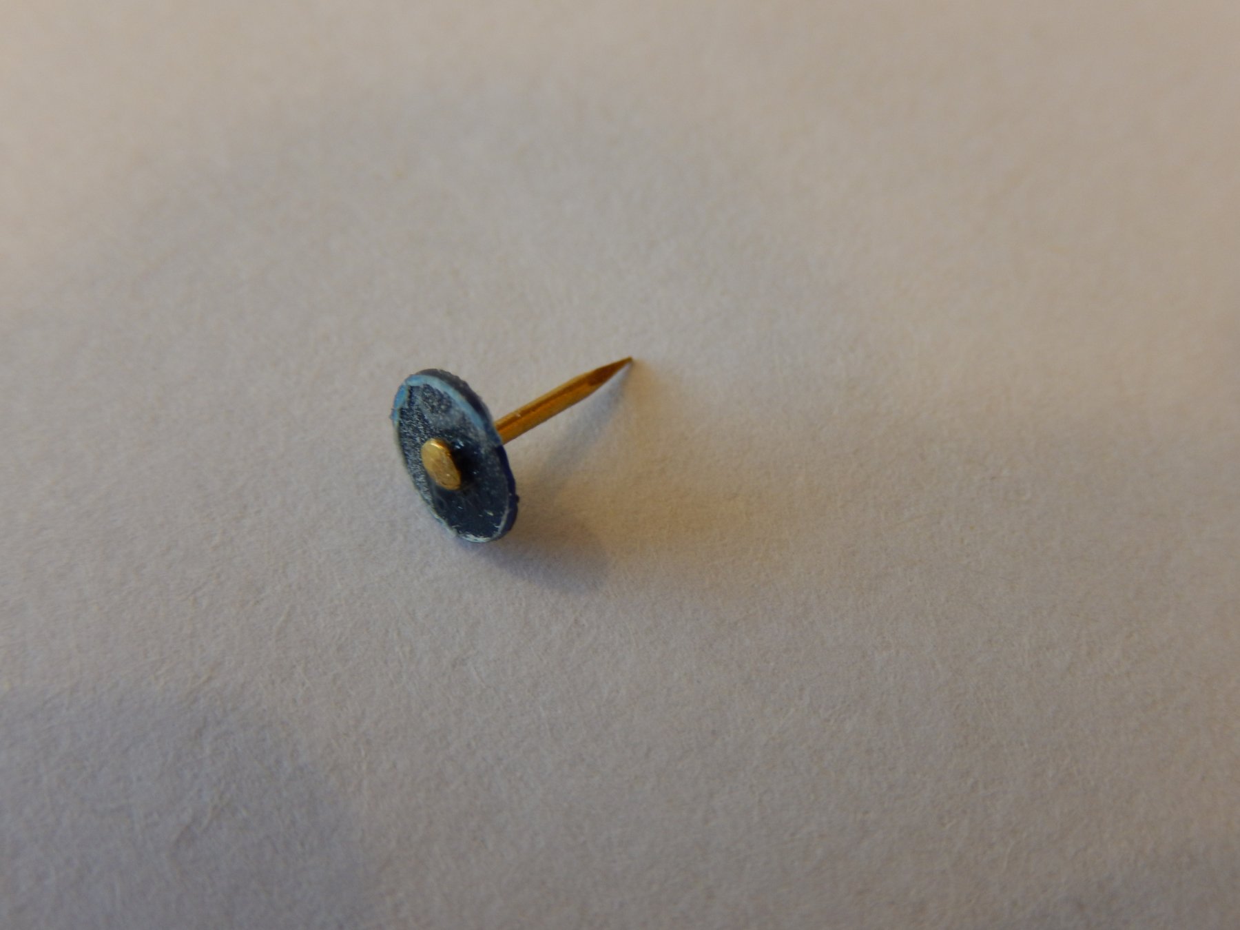
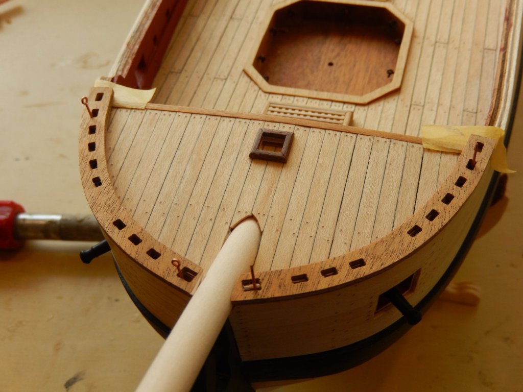
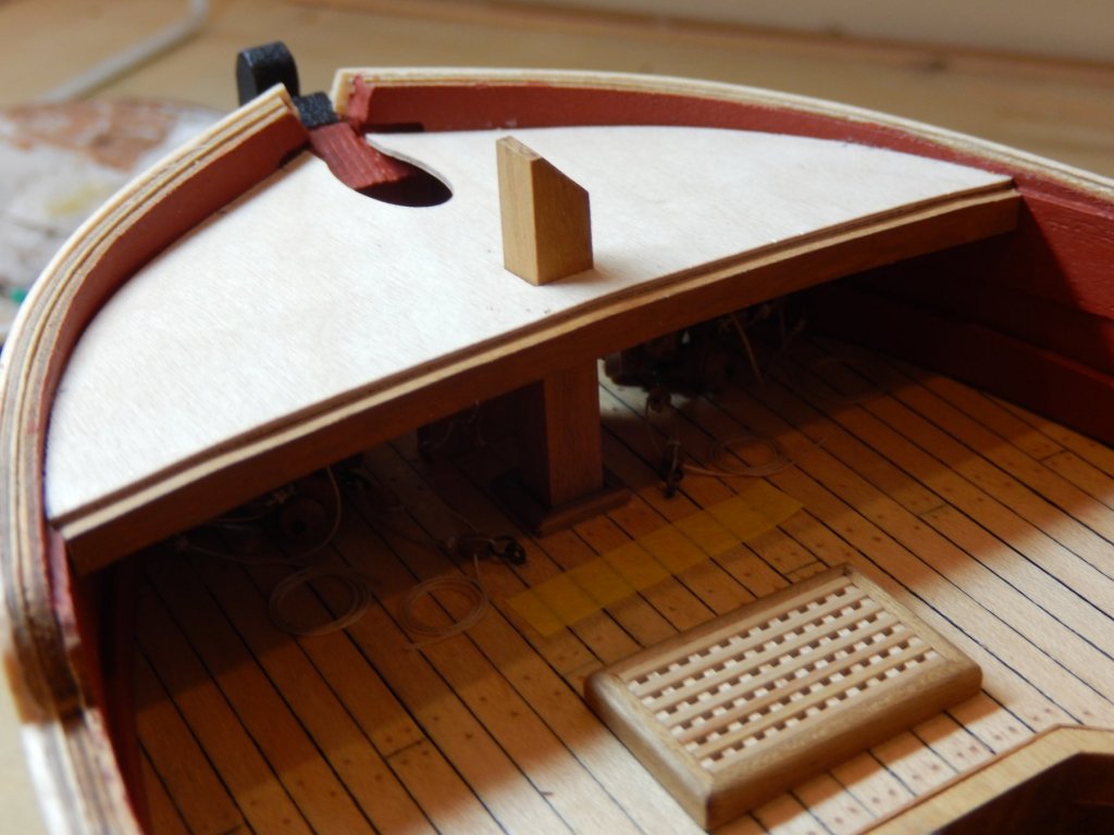
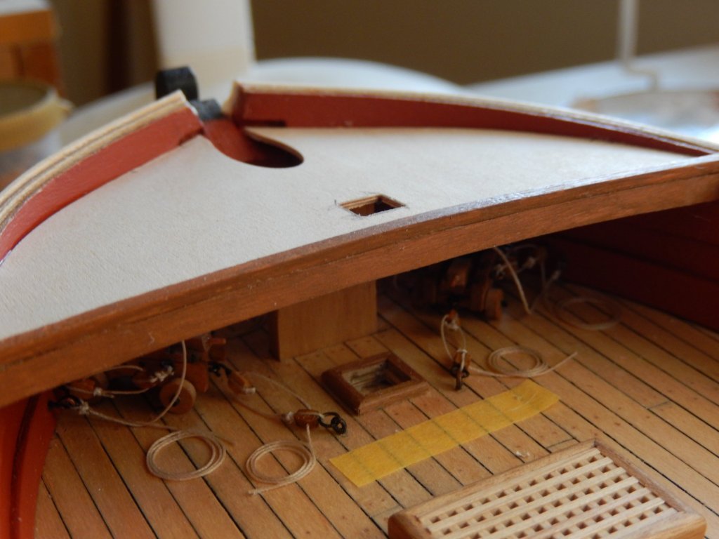
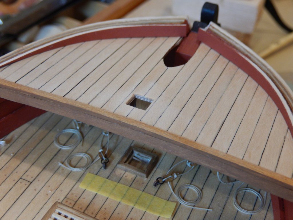
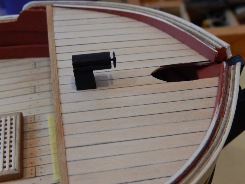
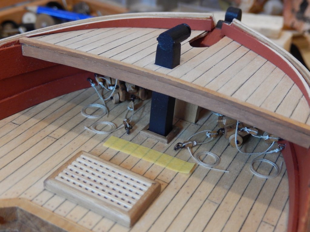
The fore deck is now on, and the planks are applied awaiting a coat or two of polyurethane before treenailing. The following photos show the process so far. I decided to place a piece of timber strip behind the the plywood deck to hide both the ply and the ends of the planking that would be glued to it. I fixed the deck support about a mm or so back from the rear edge of the ply. Also shown is a piece of 6x6mm timber in place of the galley flue. This helped to position the deck. Gluing the covering piece of strip. The tape is there to cushion the jaws of the alligator clips. Strip in place; Planking glued: Having seen Joe's log, I was aware that he had made up a galley flue replacing the kits metal casting. Once I took a look at the metal casting in my kit I now know why. I therefore decided to have a go too. I had the correctly sized timber, but had nothing to make the small disk for the diffuser (?). My wife suggested a piece of X-ray film and it worked a treat. The film was first roughly shaped,and a nail driven in to the centre. The nail was glued to the film, then placed in the chuck of my faux Dremel. The rotating assembly was very gently lowed onto an abrasive stick until it was a nice clean circle. Here is the result, dry fitted. At least it's better than the casting.


- 421 replies
-
- 9
-
-
- caldercraft
- granado
- (and 1 more)
-
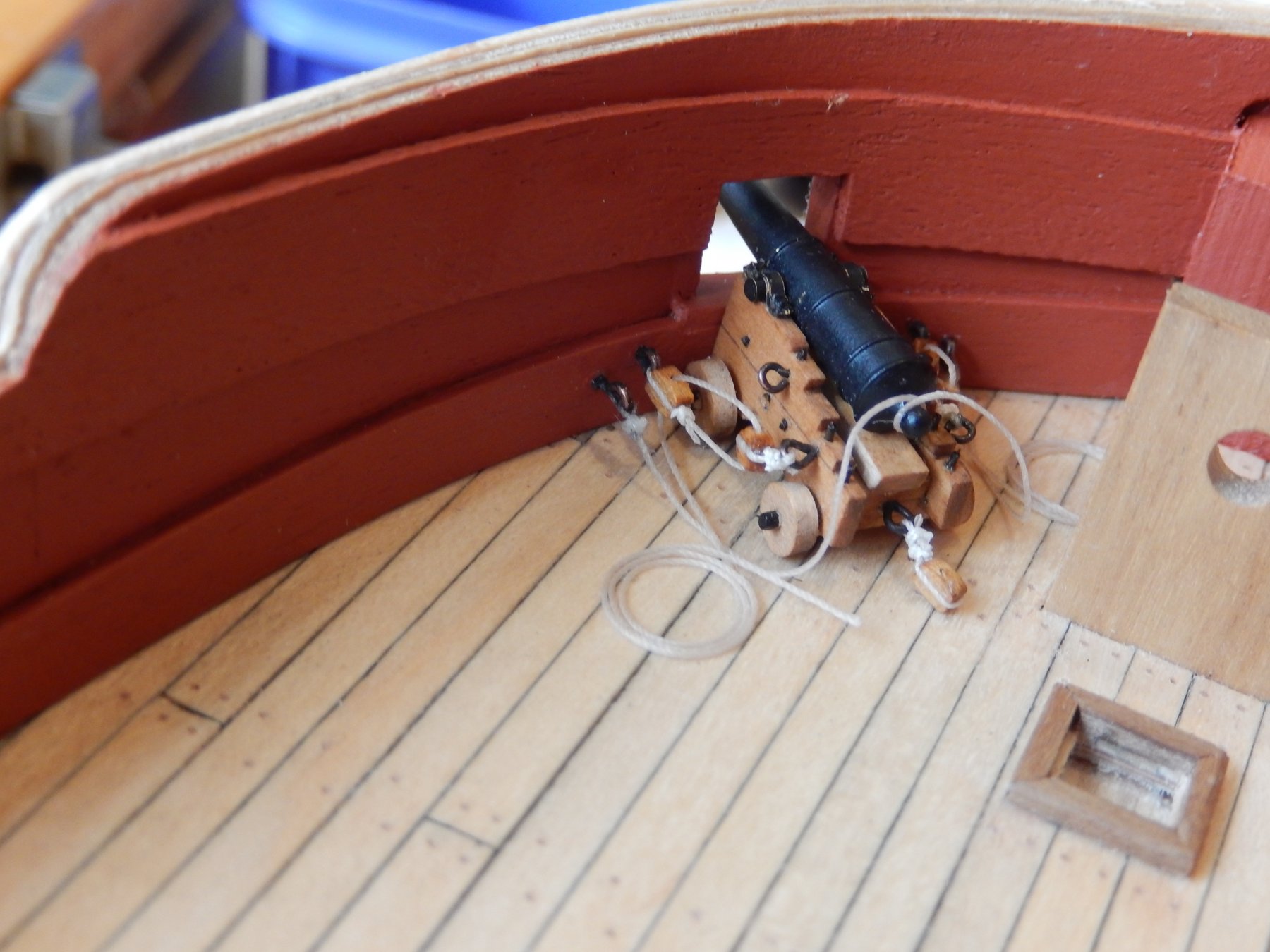
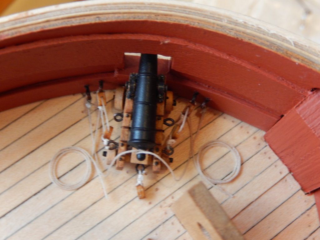
Thanks Jim for taking the time to comment and thanks for all the likes (or whatever they are called now). They really encourage. Jason You're right. Originally I tried for hooks but none of the material I had proved to be suitable for making them. Your post encouraged me to look again. Fortunately I found some etched brass fittings left over from the Vanguard that, with some work, could be made into adequate hooks. Here are the results. I hope all the mistakes are confined to these two guns (and I can now see the quoins need a touch up too) because they will be almost hidden.

- 421 replies
-
- 10
-
-
- caldercraft
- granado
- (and 1 more)
-
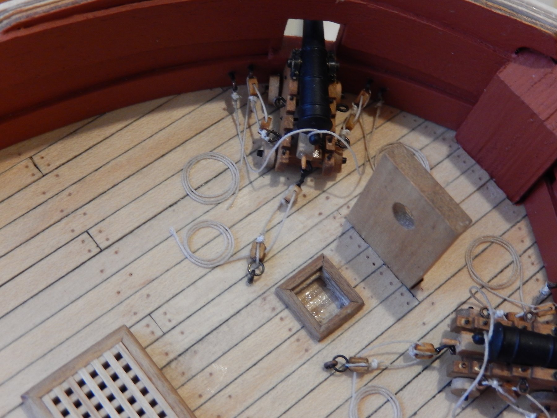
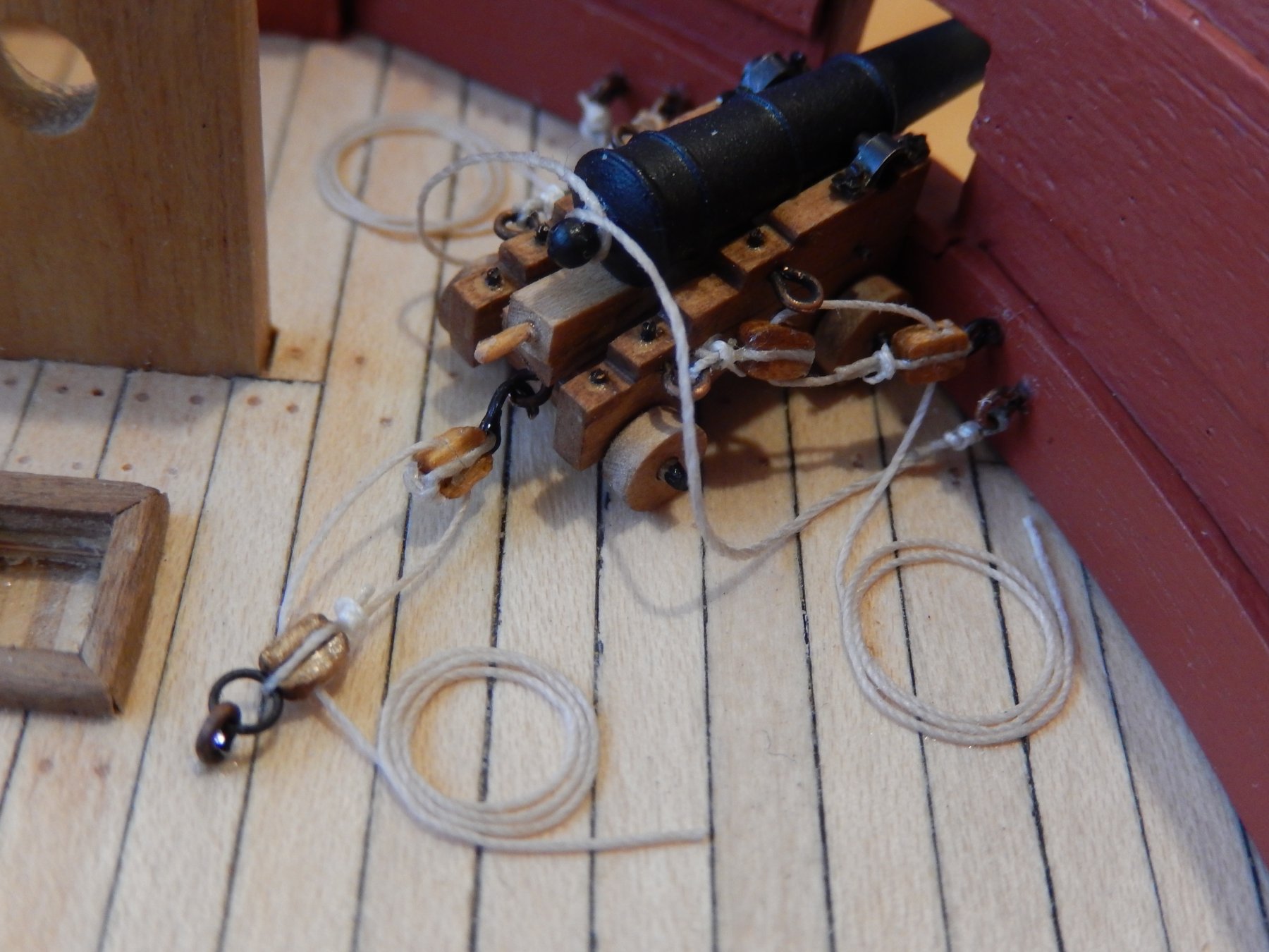
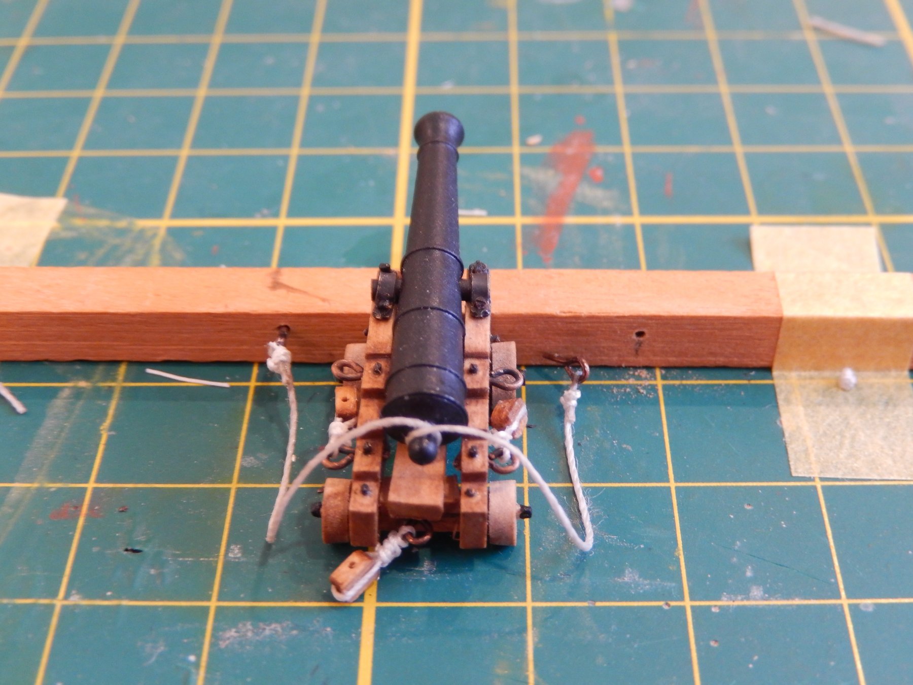
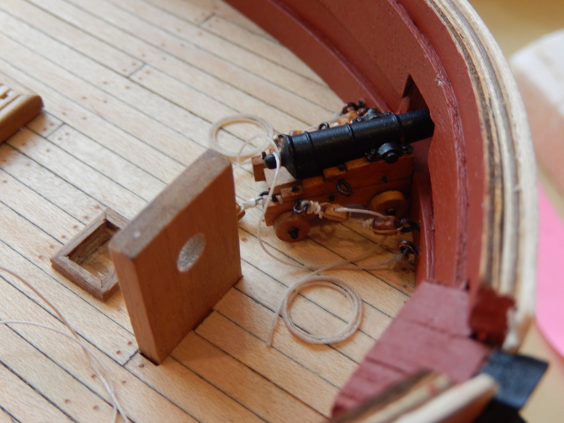
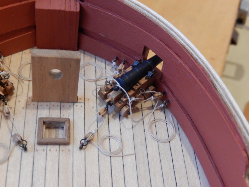
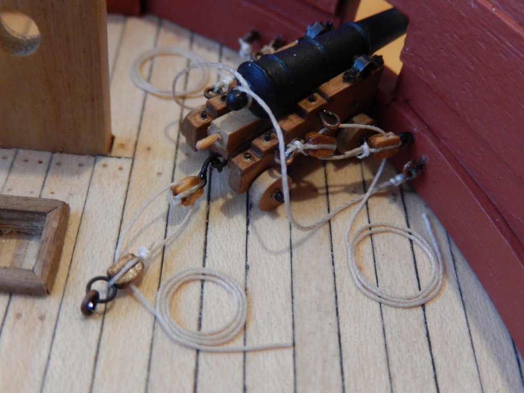
Thanks Kevin. I wish the rigging for the chaser ports guns had gone as easily. I made more mistakes doing these than any single job I can remember. At least I learnt a few things: don't put in the eyelets first - tie the lines to them off the model; adjust the length of the breeching rope off the model; and make sure the distance between the two blocks on each side of the guns provides enough room for the gun tackle fall (ie, the rope between them) to look realistic. Having not done any of the three the first time meant I had to re-rig at least once, and in one case, twice. While I am obviously a slow learner, my vocabulary has expanded if not improved. The first photo shows a simple way of adjusting the length of the breeching rope - off the model. The following photos show the rigging of one gun almost complete. The eyebolts and tackle are yet to be done. The blocks are standard off the shelf jobs and I think for the remaining rigging I will buy some of the Syren blocks. These two guns will be covered by the fore deck and will be almost impossible to see so I will leave them as is. I will be going away soon for a month and will wait until I return before ordering them - so no rigging for a while which will be a relief.


- 421 replies
-
- 7
-
-
- caldercraft
- granado
- (and 1 more)