HOLIDAY DONATION DRIVE - SUPPORT MSW - DO YOUR PART TO KEEP THIS GREAT FORUM GOING! (78 donations so far out of 49,000 members - C'mon guys!)
×

woodrat
-
Posts
835 -
Joined
-
Last visited
Content Type
Profiles
Forums
Gallery
Events
Everything posted by woodrat
-
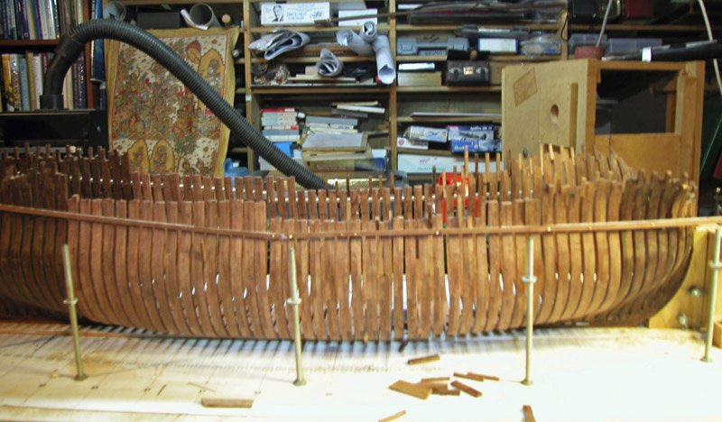
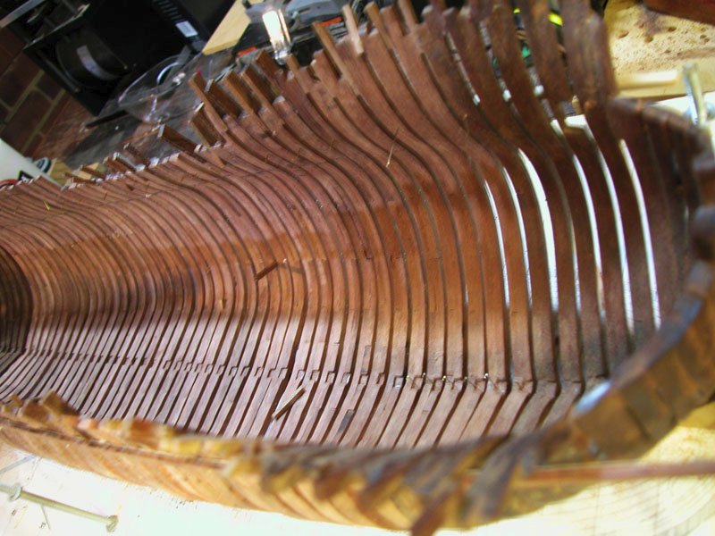
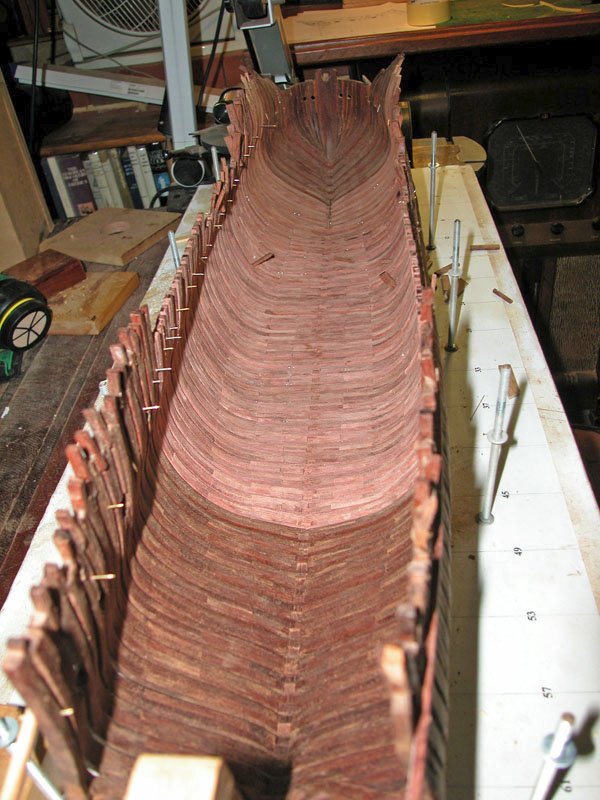
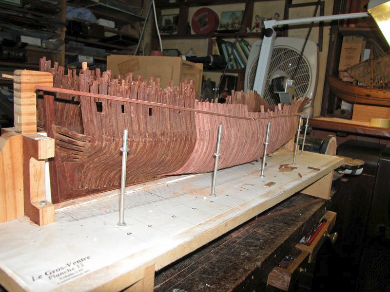
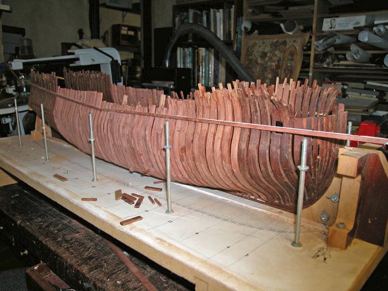
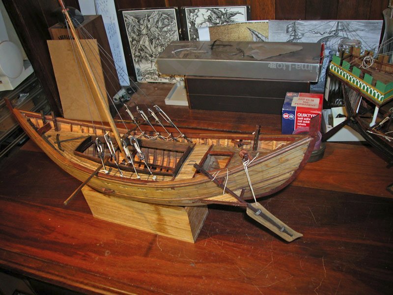
 As the immortal Arnie says: "I'm bark". After being derailed by two other builds I have girded the proverbial loins and cut some serious wood to finally finish all the frames for the legendary "Fat Belly". The frames have been cobbled onto the keel and not yet fully trued. Here are some piccies of the Beast: As you can see, the jarrah frames from years ago which were oiled are considerably darkened and make a contrast with the new frames which have yet to be oiled. Much happy and dusty woodcutting to come. Cheers Dick
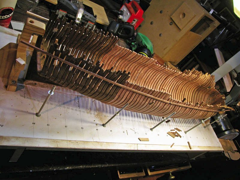
-
Oh, just the usual thimgs: tidy up ropes tie down the anchors, make a stand. But is any ship model truly "finished"? Dick
-
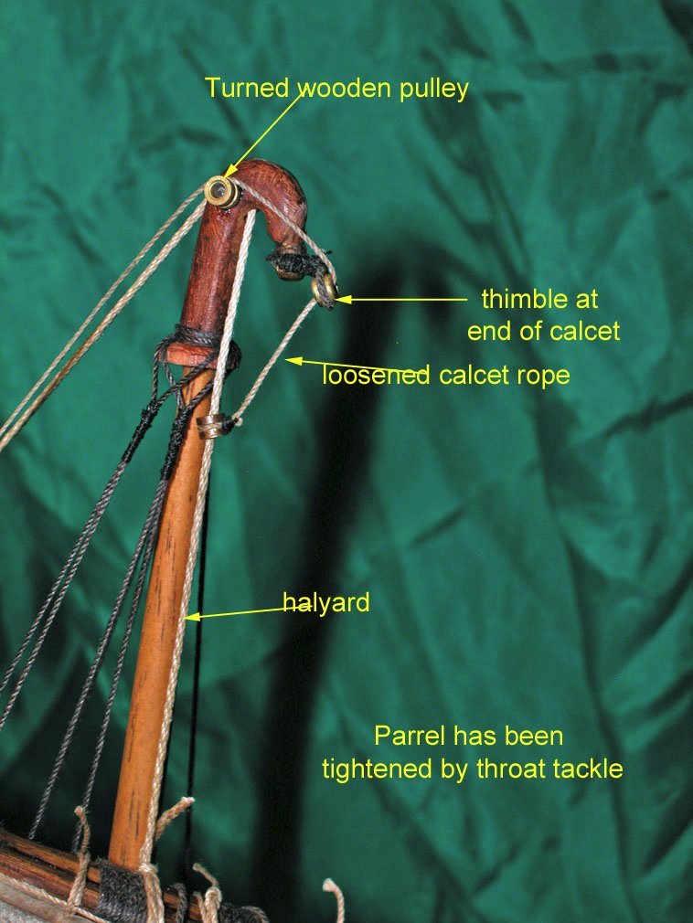
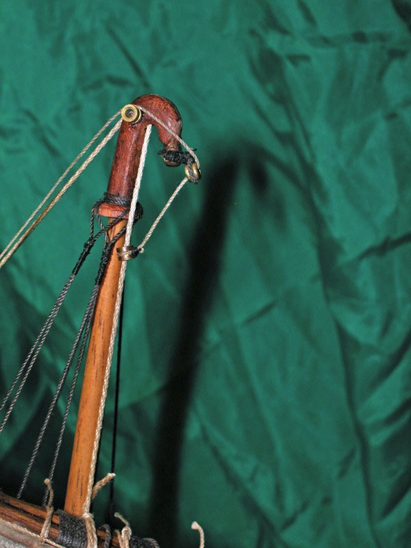
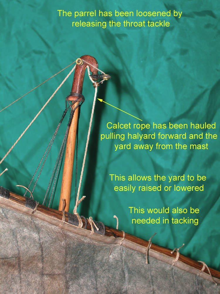
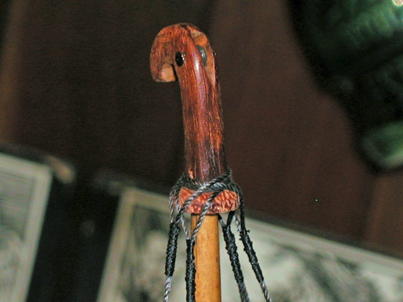
I have spent some time cogitating over the mechanism of the hooked calcet and have been helped by the fact that a calcet (the hooked carving seen at the top the mast in mediaeval and older ships of the Mediterranean) has been found in a wreck in the eastern Mediterranean, the Michael Ma'agan B. Also found were two pulley-like wooden carvings attached to the calcet. Having pondered mightily for some weeks, I have come up with a suggestion which I humbly suggest may be a working solution to the way the calcet worked to make raising or lowering the yard, as well as tacking, much easier. This system could be managed by a crew of two. The yard is raised and lowered by the halyard. The yard slides loosely held to the mast by a rope sling (or rope parrel with leather sleeve. I am doubful that parrels with trucks existed in the 7th-9th century). The rope sling is tightened when the yard is the correct level by a "throat tackle". In order for this sliding of the yard to occur, the yard must be held away from the mast. The forward slope of the mast assists in this. The purpose of the hooked calcet is to pull the halyard further forward once the throat tackle is loosened. the throat tackle has been released. The rope sling (parrel) is loose. the throat tackle is hauled thereby tightening the rope sling A rope which I call the cacet rope passes over a woodeen pulley on the calcet, thence to a thimble roped to the end of the hook and, through this, to another thimble which can slide on the halyard. Hauling on the the calcet rope pulls the halyard forward and the yard away from the mast. note halyard is close to mast I hope this is easy to follow and of course is only one possible solution. Cheers Dick
-
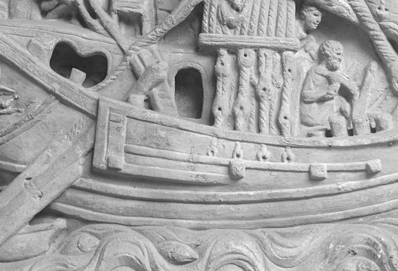
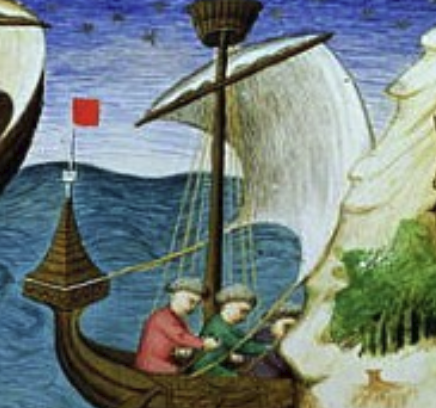
It's a famous relief from Ostia. 1st century CE. Just search on Roman merchant ship and Ostia Dick
-
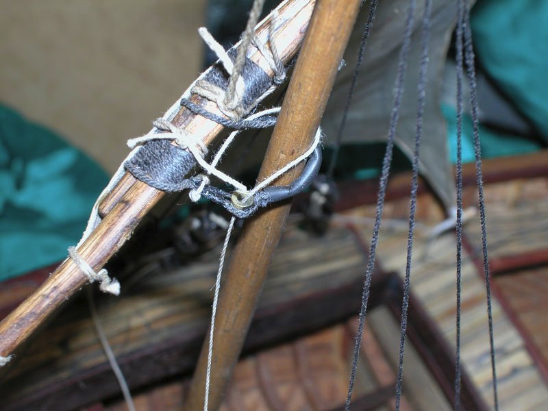
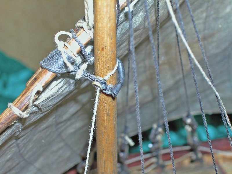
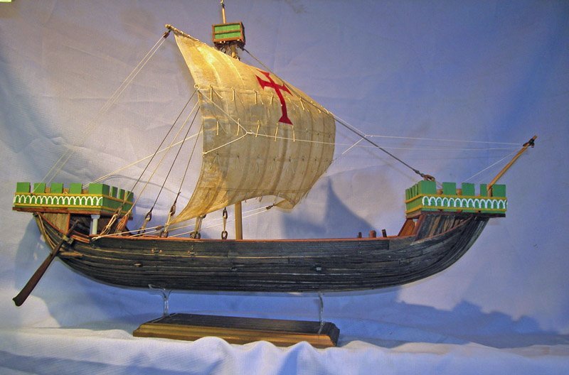
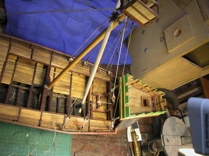
No, No No.....!! Bad idea! I had forgotten the KISS principle and was guilty of overbuilding. 😕Plus the construction for the rudder looked ugly. So off it comes and back to minimalist. Looks better I have completed the standing rigging. The rope at the base of the shroud goes through holes either side of a frame a bit like as seen in roman merchant ships The hooked pulley to allow the yard to fall away from the mast when tacking Cheers Dick
-
The rudder doesnt have to swing all the way up but if it did it would be lashed to the bitt. In any case it would only be raised when on the windward side and be out of the water. The tiller would be withdrawn before raising the rudder. Dick
-
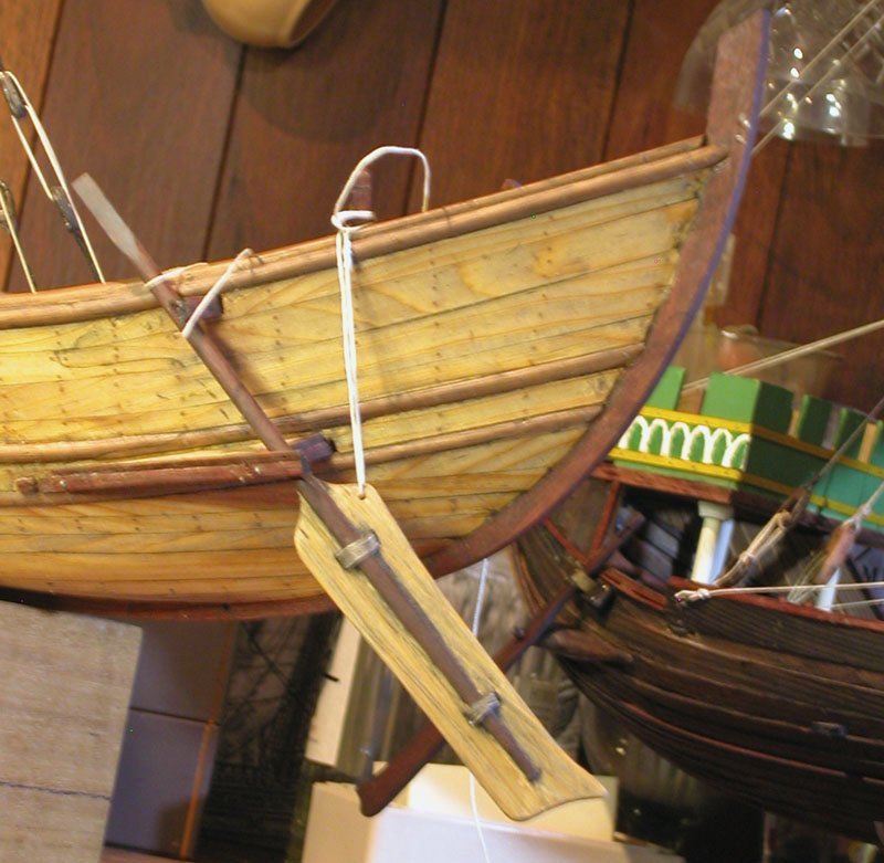
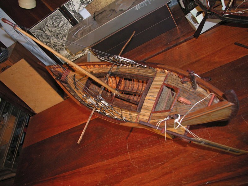
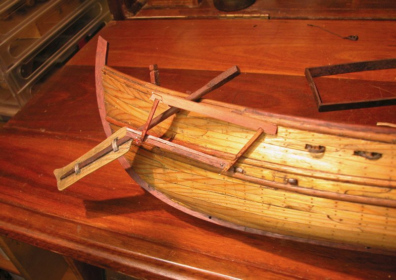
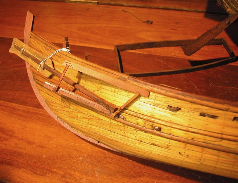
Now to finish the Yenikapi. Sometimes it's good to step away from a model for a while then come back to it with a fresh eye. Having done that, I was not happy with the rudder housing and have redone it. When this is finished it will look almost like the rudder goes inside the hull as many pictures suggest. But it doesn't! If the rudder went through a hole in the hull, it would be impossible to raise the rudder for landing and we know they did this!. Also when docking it would be necessary to protect the rudder with some casing. We see on many ships pictures with quarter rudders a structure which is triangular and I have tried to show one reason for this. This is the framing showing rudder in lowered and raised position. Planking will be installed to cover this Cheers Dick
-
Now we're lookin good. You will need to think carefully about the frames forward and aft of the tail frames. I was forced to use some cant frames as the bevelling is otherwise too much. Dick
-
Thanks, Ferrus, most kind. I suppose I could open a shop but I suspect I would starve to death! Cheers Dick
- 186 replies
-
- 1
-

-
- keelless
- reverse clinker
- (and 4 more)
-
It is most kind of you to suggest this Ferrus. I would of course love to see my models in a museum but I doubt that the local Western Australian Maritime Museum would be interested in any of my models as they have no link to Western Australia or its history. I am not sure what their fate will be when I'm gone. Hopefully the family will value them or they may end up in some yacht club. Who knows? Dick
- 263 replies
-
- 1
-

-
- nave tonda
- round ship
- (and 2 more)
-
Thanks, Roger and thanks to all the MSW people who provided feedback and likes. This was a project I almost gave up twice as too quixotic but I am glad I persisted as the model is quite attractive. The stability concerned me but the method of construction dictated the outcome as Roger says. I believe these hulcs were best suited for work in riverine conditions and shallow seas but clearly unsuited for open ocean. The question arises, if they were so unstable, why haven't we found any wrecks. The cynics would of course sneer: because they didn't exist, mate! I'm off to finish the Yenikapi vessel. I'll get out of your way now. Cheers Dick
- 186 replies
-
- 3
-

-
-
- keelless
- reverse clinker
- (and 4 more)
-
Modified decoration and perspex hull supports. Not much more to do except tidy up and put in a case (underway) Cheers Dick😎
- 186 replies
-
- 15
-
-

-
- keelless
- reverse clinker
- (and 4 more)
-
Thanks Roger . I have taken the hint and renamed the blog as you will have noticed. Dick
- 186 replies
-
- 2
-
-
- keelless
- reverse clinker
- (and 4 more)
-
But comparisons are odious. Might be a good way to lose friends,too 😏 I have a better idea. You refit the Great Harry and I'll work on Le Gros Ventre which languishes. Cheers Dick
-
Well. Damme ! You must be psychic! This is exactly what I was considering as a future build. I look forward to seeing your reconstruction of All the weaponry poking out of the sterncastle.😁 Cheers Dick
-
Thanks, Mark. The poem is an old Mother Goose nursery rhyme. Ta, Roger. The likely thing is that we already have found remains of hulcs but have labelled them as clinker built nefs. It is my view that the term hulc encompassed a range of mostly clinker built broad beamed and bluff bowed cargo nefs. Maybe there was a cohort of reverse-clinker hulcs but no evidence of them yet that is convincing. Dick
- 186 replies
-
- 3
-
-
- keelless
- reverse clinker
- (and 4 more)
-
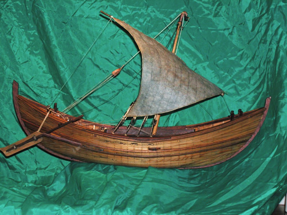
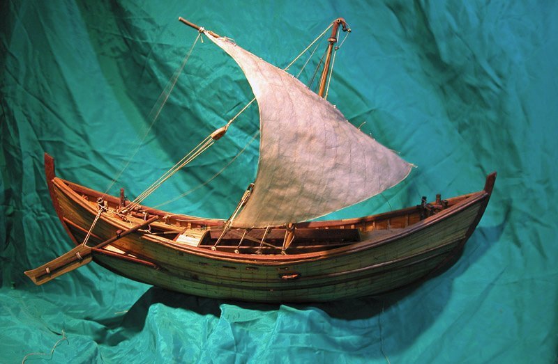
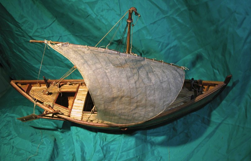
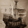
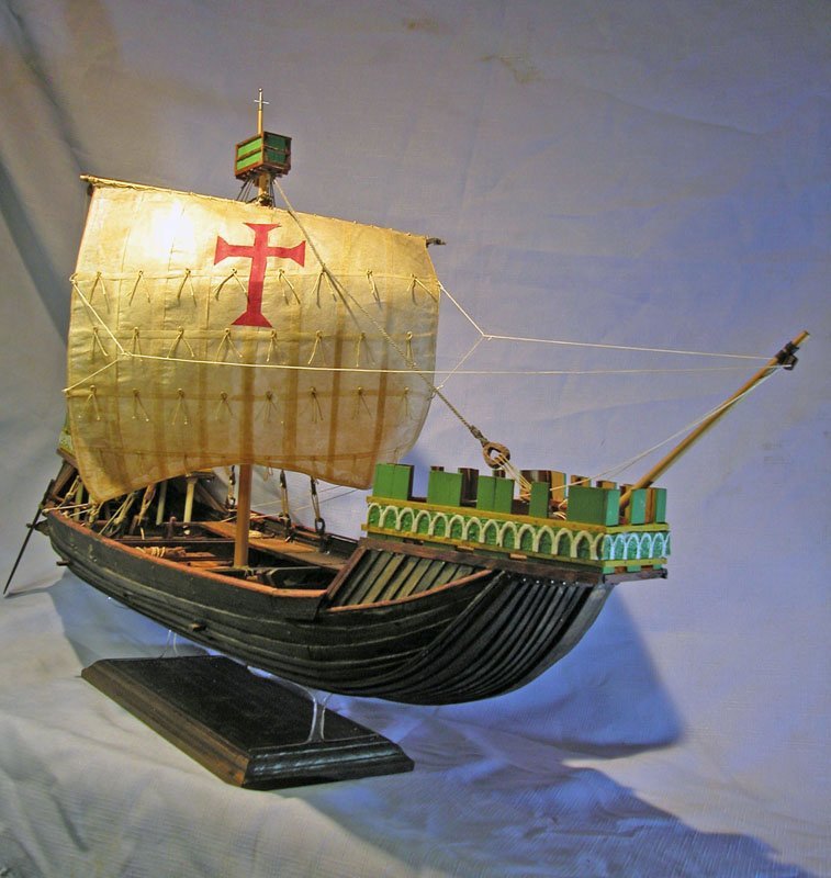
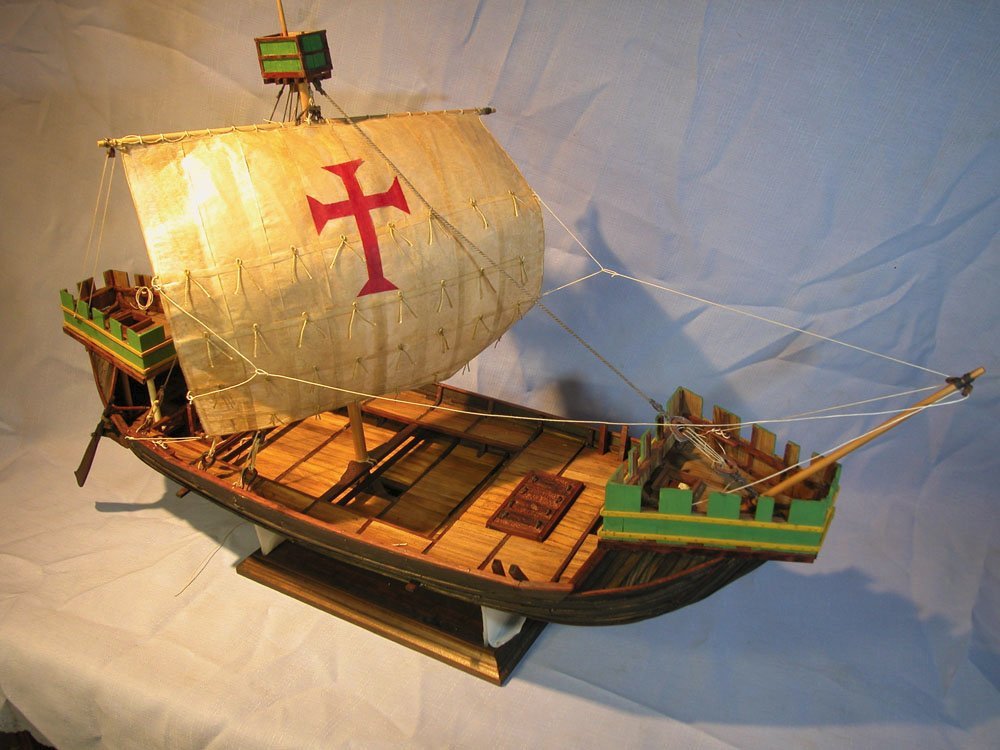
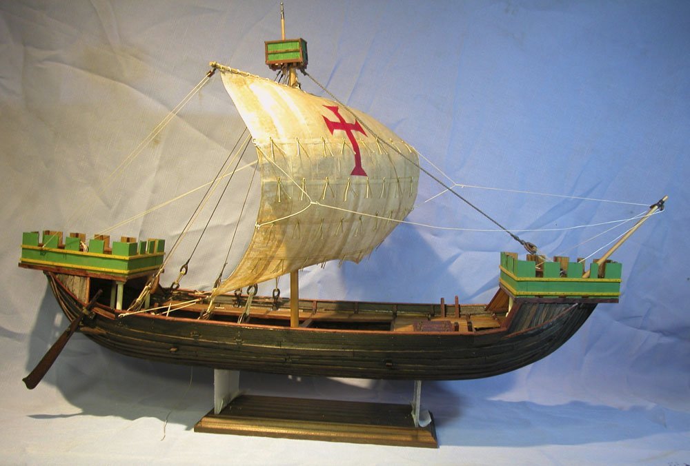
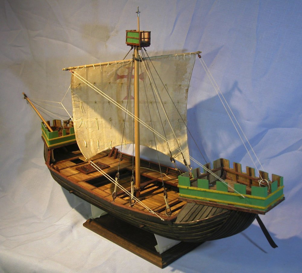
Some views of the vessel with sail deployed. Almost finished I saw a ship a-sailing, A-sailing on the sea, And it was full of pretty things For baby and for me. There were sweetmeats in the cabin, And apples in the hold, The sails were made of silk, And the masts were made of gold. The four-and-twenty sailors That stood between the decks, Were four-and-twenty white mice, With chains about their necks. The captain was a duck, With a packet on his back, And when the ship began to move, The captain cried, "Alas, alack!" I saw a ship a-sailing, A-sailing on the sea, And it was full of pretty things For baby and for me. Merry Xmas Dick
- 186 replies
-
- 10
-
-
-
- keelless
- reverse clinker
- (and 4 more)
-
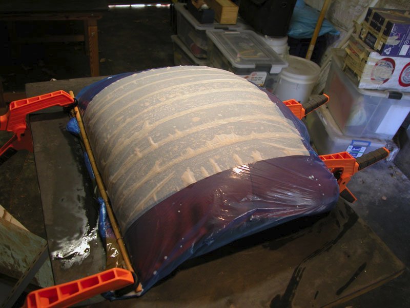
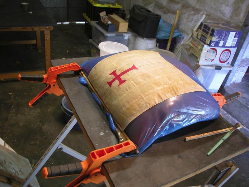
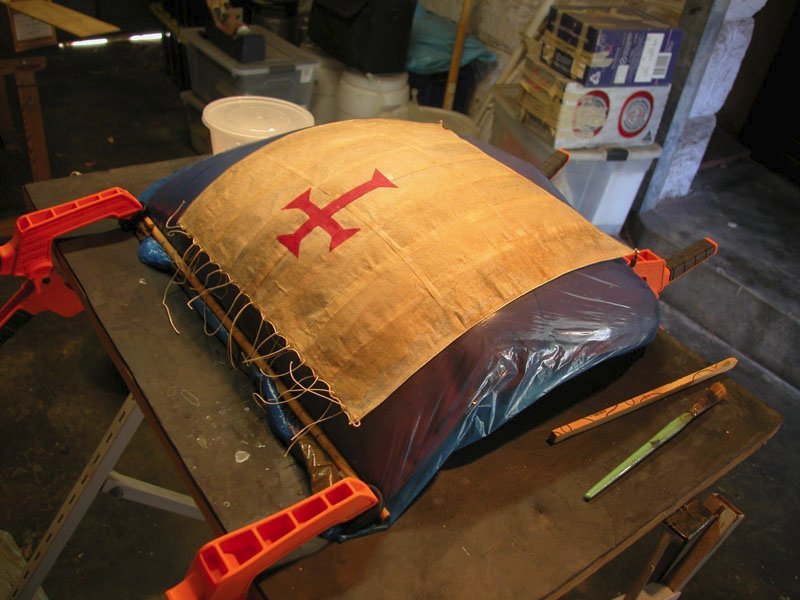
To show the sail bellying to a moderate quartering wind, I used a cushion inside a plastic bag secured to a firm surface and coated with silicon lubricant. Strips of Silkspan were held together with watered down wood glue. Cross bands applied. Sail coloured with diluted wood dye. Silkspan is too white. I doubt mediaeval sails were ever white. A Templar cross was made of Silkspan and applied. Bolt ropes and cringles applied, robands inserted. I have avoided stitching as the Silkspan crinkles and tears easily. I realise that this sail not accurately depicting a real sail but this is a decorative model and I wanted to give an overall impression of a sail bellyingrather than just hanging limp. Double reef points and loops applied to both sides of the sail. Dick Woodrat
- 186 replies
-
- 6
-
-
- keelless
- reverse clinker
- (and 4 more)
-
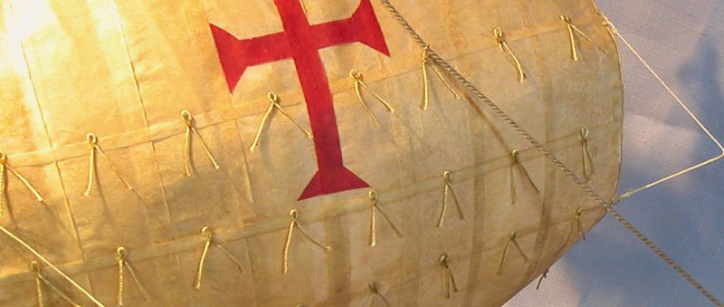
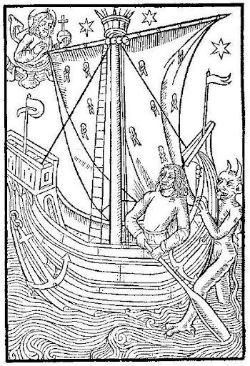
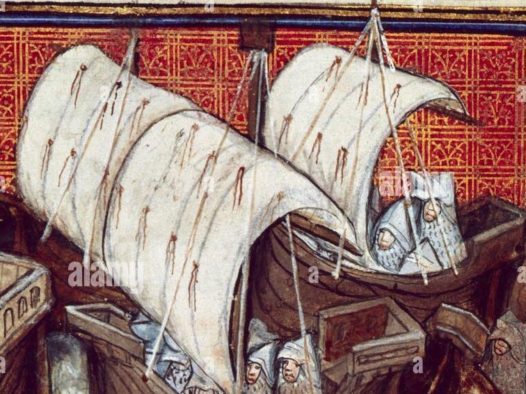
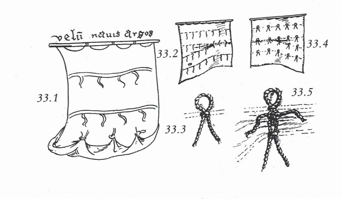
And now to the knotty problem of how the mediaeval tar shortened sail. There is no doubt that in the 13th century, bonnets had not yet been introduced but there is ample evidence of reef points in contemporary illustrations. The patterns of reefpoints seen are legion, varying from a single band to multiple bands of reef ponts to seemingly random scatterings of points. It is my contention that reefing was not done using the techniques of later centuries. For one thing I believe sailcloth was somewhat stiffer and hence difficult to hand. Something more mechanical is needed. There were no footropes so it is unlikely that reefing by hardy matelots at the yard occurred during a blow although furling was done in harbour by sailors astraddle the yard. It is possible that the yard was lowered somewhat to allow the sail to be shortened from the deck, much as was the case with the later bonnets. The contemporary illustrations once again come to our assistance and, in this regard, I acknowledge the research and lateral thinking done by the early contributors to The Mariner's Mirror Robert Morton Nance and Harold Brindley. To these I owe the concept which , I believe, likely explains the the strange appearance of reef points in this age. I have elected to use their concept in my model. Many illustrations are seen where reef points are double and with a loop as seen in this woodcut fromthe Compost et kalendriers des bergiers 1493 These strange points were on the forward and after side of the sail. There are often three rows of reefpoints Mr Nance contends that the double points and loops were used to enable one or two sailors to sequentially reef the sail by passing the double points of the upper reef point "over and through the loop on the the lower band " then a reef knot is tied on the standing part. This is repeated on the other side. This concertinas the sail. (Mariners Mirror Notes, Vol VI, No 3, pp 85-86, March 1920) I have decided to use these reef points in my model although I baulked at showing the sail reefed. Cheers Dick
01.png.f55b4511894a1c879eda96615d4d2380.png)
- 186 replies
-
- 4
-
-
- keelless
- reverse clinker
- (and 4 more)
-
Just a question about mediaeval robands. My impression is that the robands of this period in the north were a simple rope passed through a grommet in the sail and tied above the yard with a reef knot. My books give no evidence for this. Certainly the complicated double robands of the 17th to 19th century would not be appropriate. However, looking at some contemporary ilustrations, some seem to show ribbon-like robands, a little tapered at the ends. What was the scandinavian practice or dont we know. Sails dont preserve well. Dick
- 186 replies
-
- 1
-
-
- keelless
- reverse clinker
- (and 4 more)
-
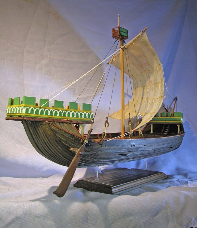
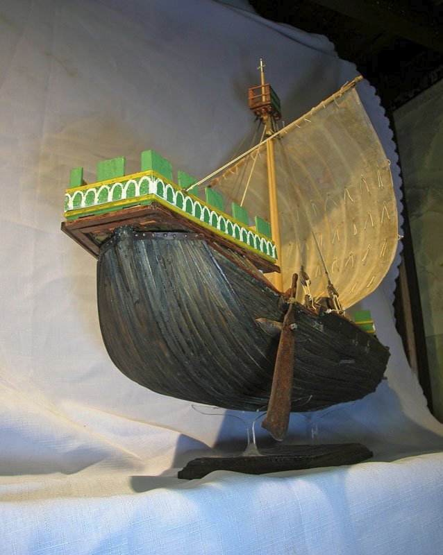
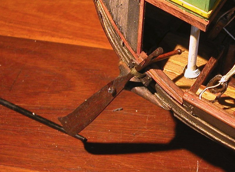
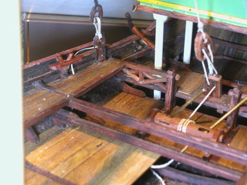
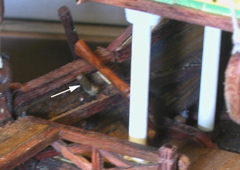
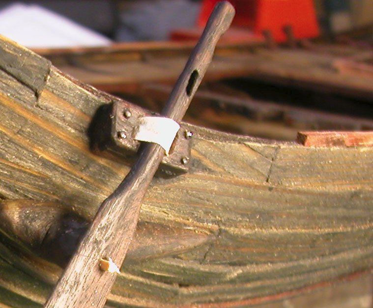
Some pics of the quarter rudder The arrow points to the wooden rod holding the leather strop inside the bulwark. Removal of this by the steersman allows rapid raising of the rudder. Cheers Dick
- 186 replies
-
- 6
-
-
- keelless
- reverse clinker
- (and 4 more)
-
I used a strip of Silkspan doubled lengthwise glued and dyed brown. Seems strong. But, in order to be able to raise the rudder, this has to be released quickly. I fixed one end to the wood block against which the rudder moves and led the other end through a slot where it is held with a wooden dowel which can be pulled out quickly by the steersman. I have no evidence for this but they must have done something like this or lost a lot of rudders. Dick
- 186 replies
-
- 3
-
-
- keelless
- reverse clinker
- (and 4 more)
-
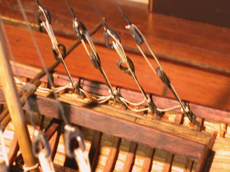
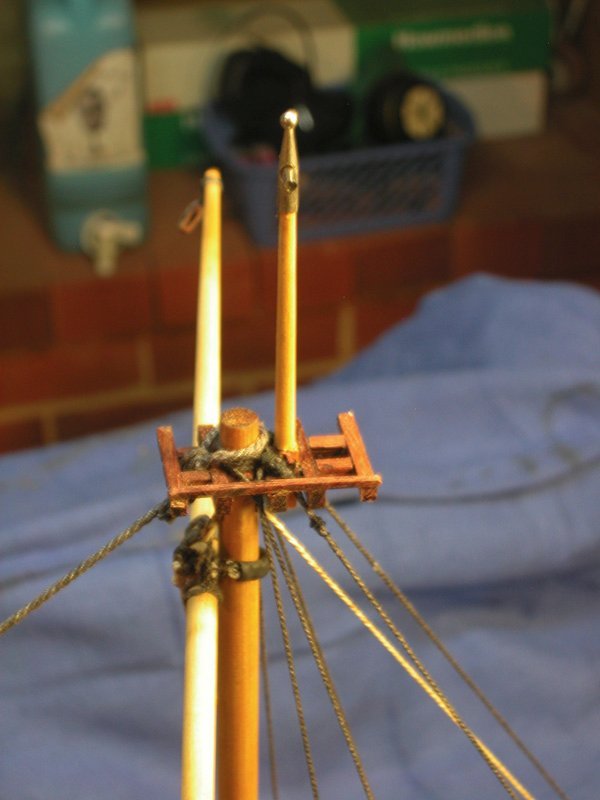
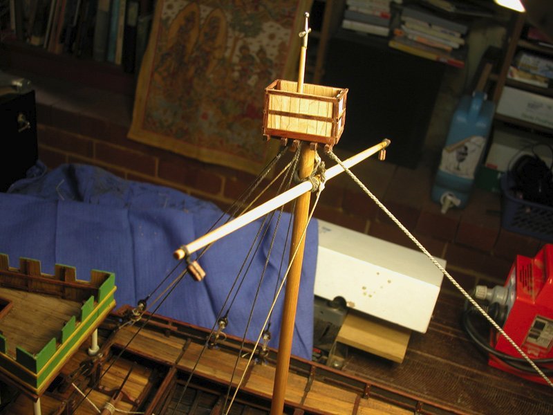
Thanks, Steven. The tamu file agrees with my impression of hulcs. Here is the maintop with the forestay and shrouds rigged. The yard is crossed. I was not convinced that parrels were appropriate so I opted for leather wrapped rope. There is a rope for tightening the leather strop. Cheerio Dick
- 186 replies
-
- 6
-
-
- keelless
- reverse clinker
- (and 4 more)
-
According to Wolfram zu Mondfeld (Historic Ship Models): from the 13th century onward the windlass drums were usually octagonal or hexagonal in cross section. As the speculative hulc predates this by at least a century, it would seem sensible to have a cylindrical drum. But of course local variation must have been endless. Dick
- 186 replies
-
- 2
-
-
- keelless
- reverse clinker
- (and 4 more)