HOLIDAY DONATION DRIVE - SUPPORT MSW - DO YOUR PART TO KEEP THIS GREAT FORUM GOING!
×

woodrat
-
Posts
834 -
Joined
-
Last visited
Content Type
Profiles
Forums
Gallery
Events
Everything posted by woodrat
-
 I would suggest only using length of keel/breadth of midship frame and forget I ever mentioned length between perpendiculars. I still suggest 2.5 as a starting point. If you are planning POB at large scale, you are going to need at least a jigsaw or a fretsaw and elbow grease and I would suggest good quality plywood. Dont rush in. I spent years collecting and making tools before I cut the first wood for my first scratch build the USF Essex. Use the collective hive mind of the MSW tribe to its full extent. Dick
 -
are you talking of length of keel or length between perpendiculars? It makes a difference. Let us assume it is length of keel. For venetian galleon 16th century Pre Theodoro gives keel length to breadth ratio as about 2.6:1. This would be higher if you use length between perpendiculars. For an english galleon of 16th century length to breadth about 3:1. BUt thise is not likely for a 15th century nao. I imagine spanish would be similar to venetian in most regards. As far as 15th century practice, have a guess but I would say 3:1 is a tad high and would tend to go for the ratio of 2.5:1 (I base this on the figures given for venetian naves in F C Lanes Venetian Shipbuilders of the Renaissance. There were no set rules and shibbuilders varied. Dick
-
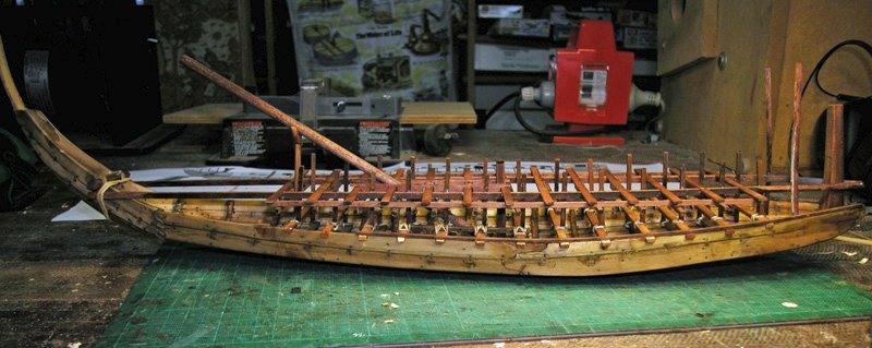
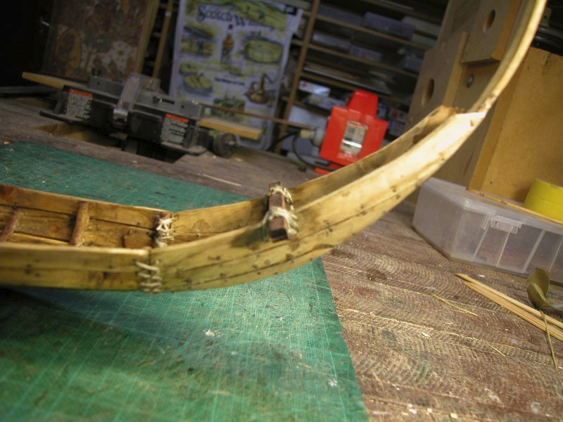
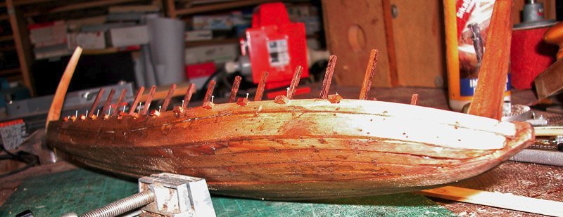
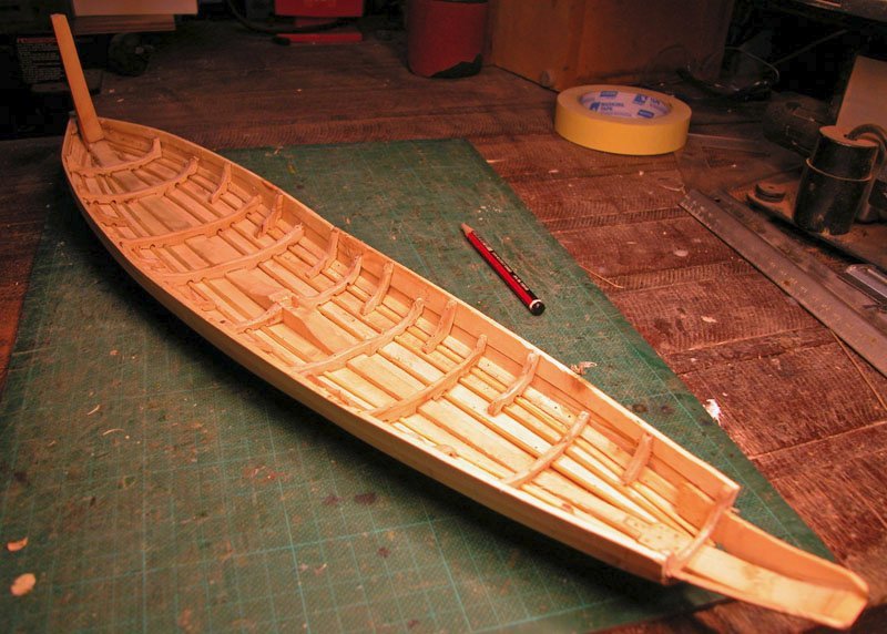
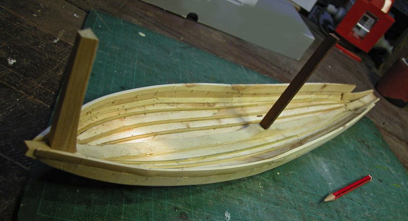
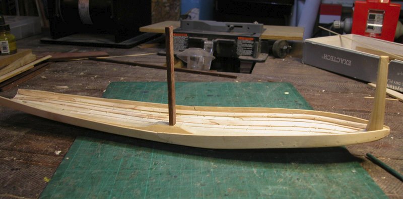
Thanks, Mark. Here are the missing pics. The mast is seen lying on its crutch. The upper bank of rowing benches is now added Cheers Dick
- 142 replies
-
- 10
-

-
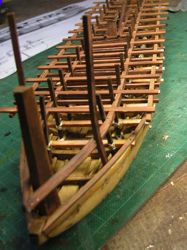
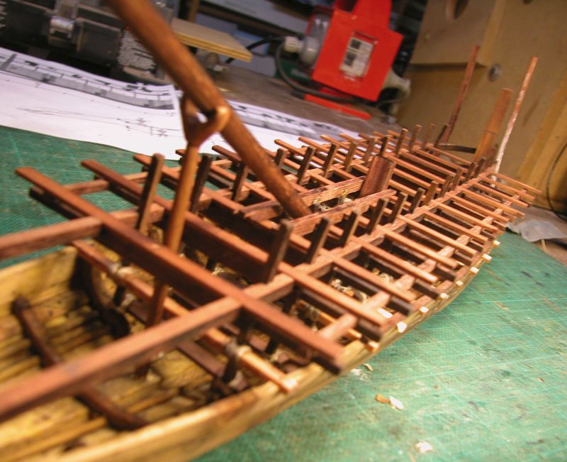
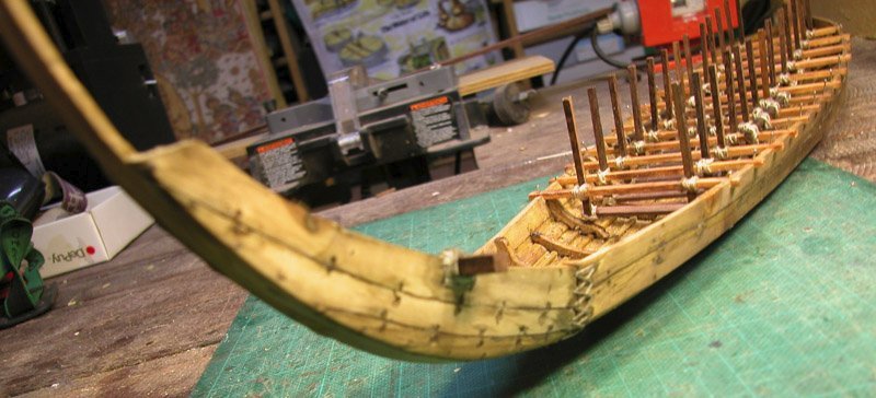
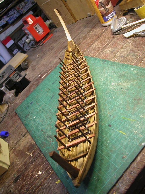
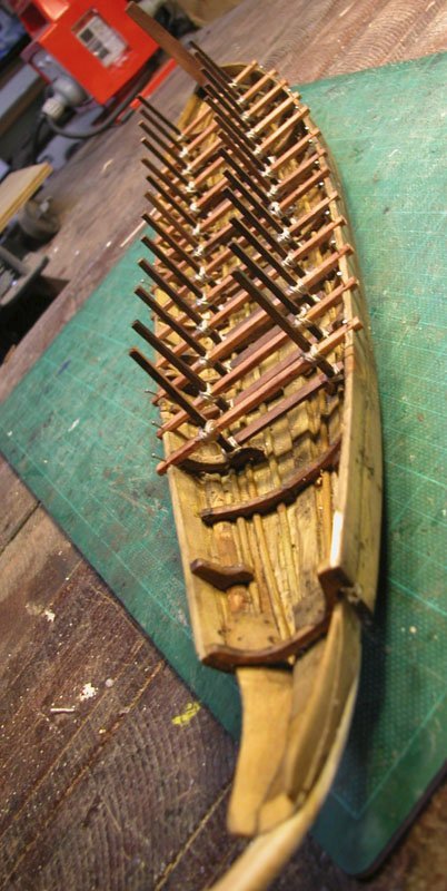
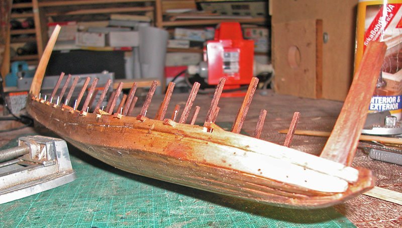
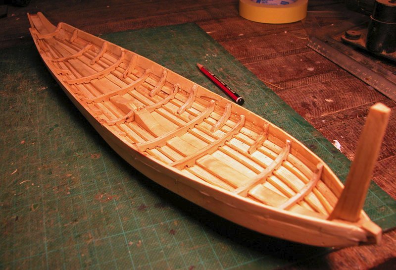
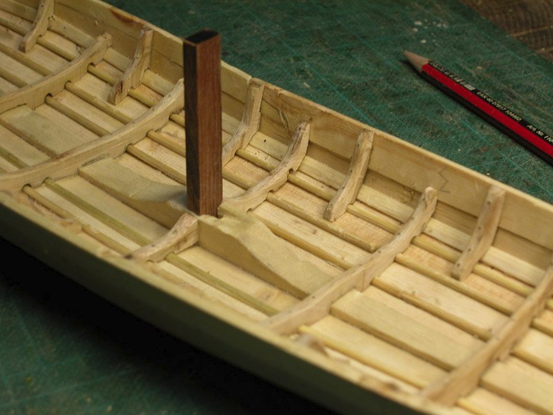
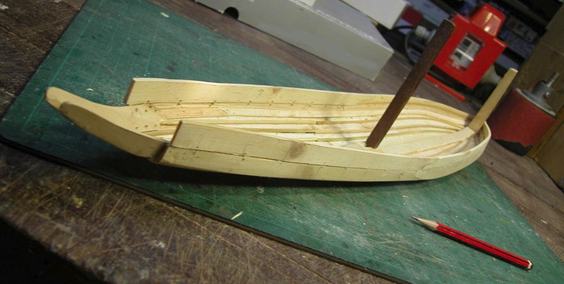
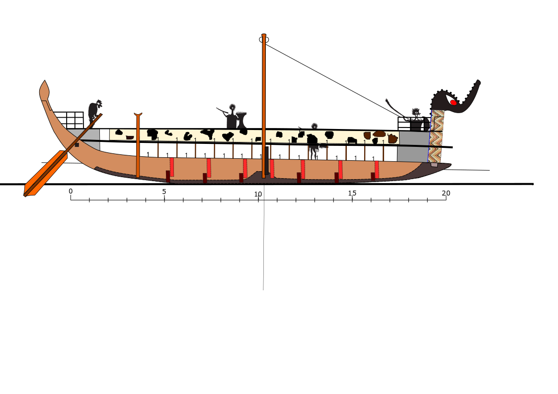
I have added the upper bank to the galley. The foot rests can be seen. Note that there will be a cutout in the central deck to allow the mast to be disconnected from the histopede (the upright on the keel plank to which the mast is lashed and to be tilted down onto the crutch (histodoke). The yard could then be furled and stored. The more I think about it the more sense there is in an upper and a lower bank of rowers. It would mean there are two teams which could row in shifts . When a maximum effort is required, both teams could row. When storming a beach , the lower rowers could row onto the beach while the upper team gets into their armour and weapons and prepare to attack or repel boarders Cheers Dick
-
There is a basic problem with using the Mataro vessel as the basis for a model in that , although built by someone who had knowledge of contemporary shipbuilding techniques, he was building it for reasons that are foreign to us. This vessel was a votive object. That is to say, it was an object of art made to celebrate a religious event: a salvation, a conversion, or a simply as a form of thanksgiving. Maybe it was even commissioned by the catholic church, who knows? The completed work of art was presumably meant to be hung from the rafters of a church and viewed only from certain angles. It was of supreme disinterest to the builder to accurately depict a scaled down replica of an existing ship (something which obsesses us today but did not start to occur till the seventeenth century). What was required was an object which conveyed to the lay person the idea of "ship" without obsessionally replicating it. Consequently, the dimensions of these votive ships were distorted and unreliable, Such votive "ships" were not uncommon in european churches during the middle ages and, it is my belief, such "models" were copied by artists to depict the vessels of the time. A classic example is the series of depictions of carracks produced by the master WA which were clearly drawn from model ships. You have to wait for the Renaissance artists such as Carpaccio who drew from real ships to reduce the distortions. So, by all means use the Mataro as a guide but I would suggest that reproducing an"accurate" reproduction of a carrack is largely guesswork. Even the archaeological remains are fragmentary and to some degree distorted but still give the best information on construction techniques. I'll get out of your way now (homage to John Clarke, sadly missed). Dick
-
I was strongly considering installing a steering oar on my mycenean galley rather than a quarter rudder. But this would not be likely in a Venetian round ship. Dick
-
It looks rather like a bragozzo, which is venetian, although I think they had lug sails. Dick
-
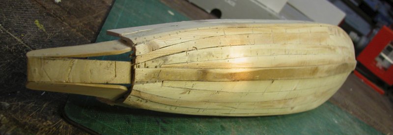
Yes. You can see some projecting planks on the after part of the hull over which the stern sleeve slides. The sewn ropes are just to hold the stern on and allow disassembly (see Khufu royal barge). The longitudinal internal stringers are for holding in the caulking . Dick
-
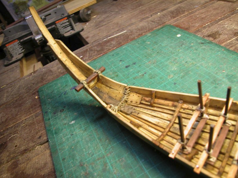
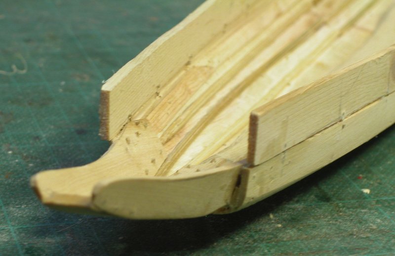
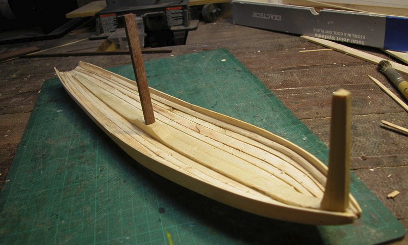
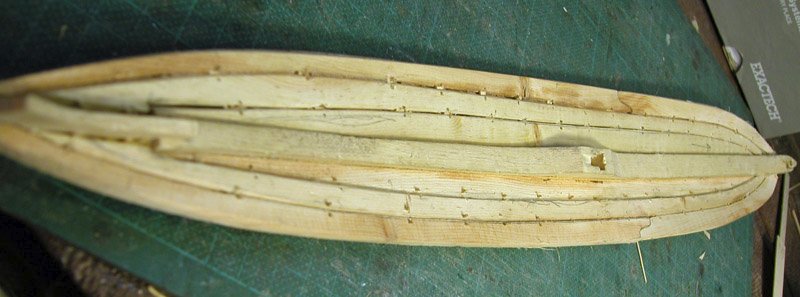
The stern module has been attached. It is my contention that these war galleys may have been required to be transported over land (see the Gurob ship cart) as was done later in classical times over the isthmus of Corinth. So it would have been advantageous to be able to dissassemble the craft partly. Hence the stern module is designed to slide into place and be held by sewn ropes as was the case with egyptian vessels. Also seen here is the through-beam in the stern upon which the steering oar bore. This also is fixed by ropes. Cheers Dick
-
Yes, its absurd to think that the mycenaeans were not aware of egyptian shipbuilding practices and used them. The method of attaching the stern module is also adapted from the Khufu barge. The flat bottom and beaching sled on the bow make bringing the boat ashore much safer. Dick
-
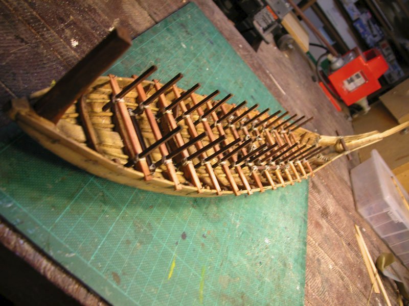
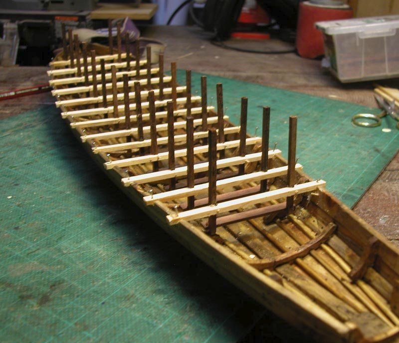
Thanks, Steven. I had seen most of these "reconstructions" before but did not want to become influenced by them. As it is, they have reconstructed single banked galleys whereas I wish to produce an idea of how a double banked galley could be built keeping iin mind the materials available in the Bronze age. I have inserted the lower thwarts and made them integral with the vertical stanchions and the rowers' foot rests. I made a rough jig to ensure that all these Frames are uniform as they will be used to construct the upper rowing benches and central walkway The thwarts and stachions are lashed together as metal nails would not have been used. Note the ladder-like appearance produced by the vertical stanchions as seen in the pottery images from the time. The next step is firstly to make the curved stern and then I will be able to start on the longitudinal "wales" to which the upper benches will be attached Cheers Dick
-
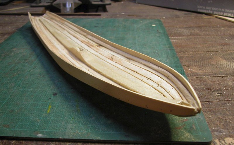
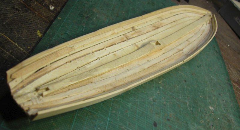
The frames and foothooks have been inserted. This gives resistance to twisting, The hull is surprisingly strong even without the frames. This shows the histopede to which the mast is lashed Dick
-
For ease of reference for those interested, I have inserted an index of the build on page 1. Thanks to those who have supported this build. Cheers Dick😁
-
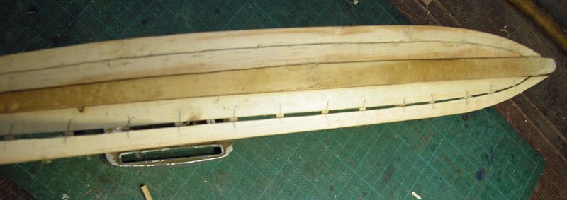
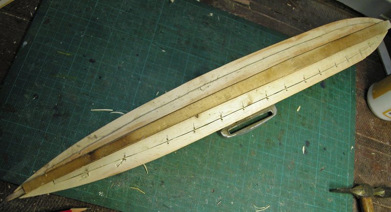
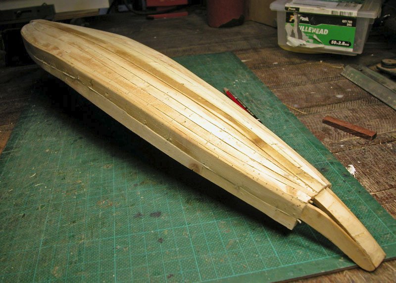
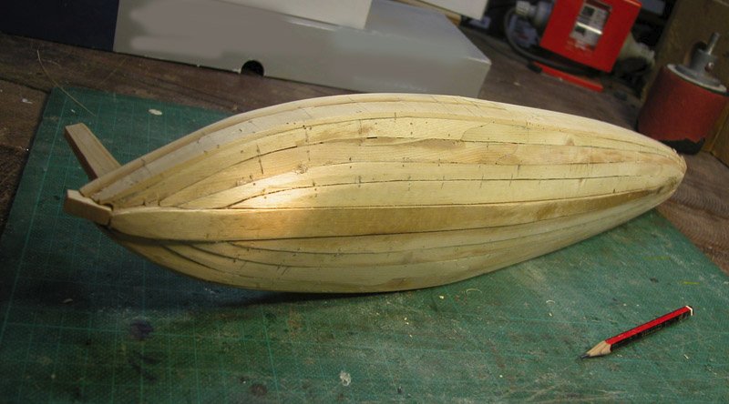
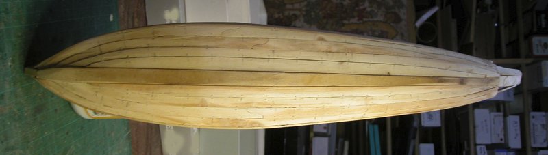
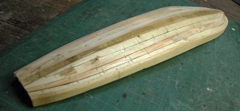
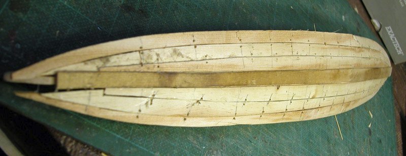
The planking is complete although the caulking remains to be done. Note the construction at the after end which is in preparation for the stern module to be attached like a sleeve. Some reinforcement of the prow was necessary but this is not a true beak (which came later during the geometric period or Iron Age (maybe worth another model?). Dick
-
I would suggest The Anatomy of the ship: the ships of Christopher Columbus by Xavier Pastor. Much of its Santa Maria is based on the Mataro Nave Dick
-
The planking of the hull is complete except for the sheer plank and capping. I am debating how much internal framing is needed. I dont want the hull to be too heavy. The stern section will be made separately as a module which will be slotted onto the hull in a similar way to the Khufu barge (I have a cunning plan!). The plank joins internally will be sealed with ribbands (and presumably some water excluding substance available in the Mediterranean (?resin or pitch) Cheeers Dick
-
I think you will find I have detailed these in the initial pages of this build. I have used only sources contemporary with the vessel depicted (15th century CE). No modern reconstructions were used. Dick
-
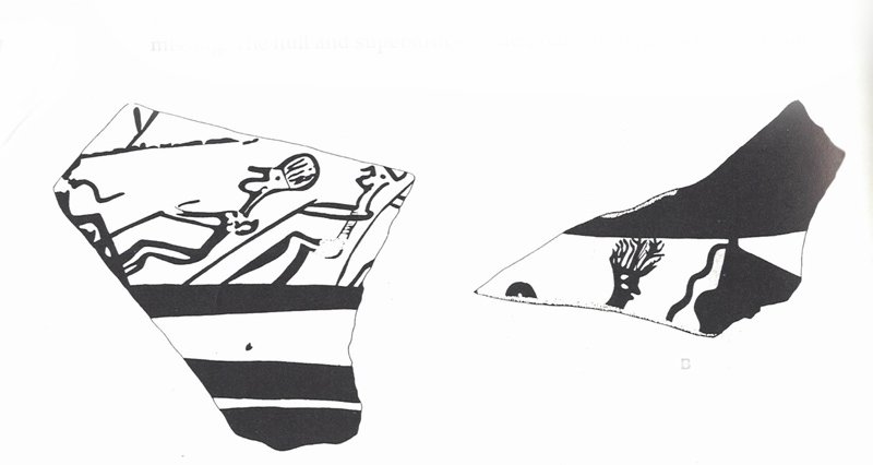
No, but his hair is like the feather headdresses seen in depictions of mycenaean warriorsWachsmann after Morricone 1975 Cheers Dick

-
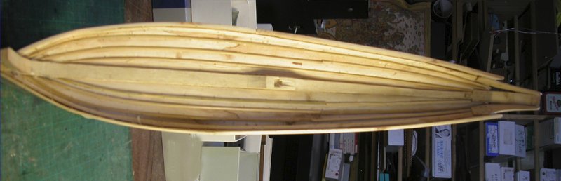
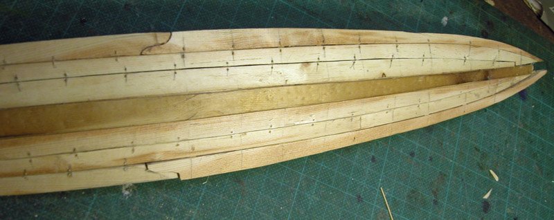
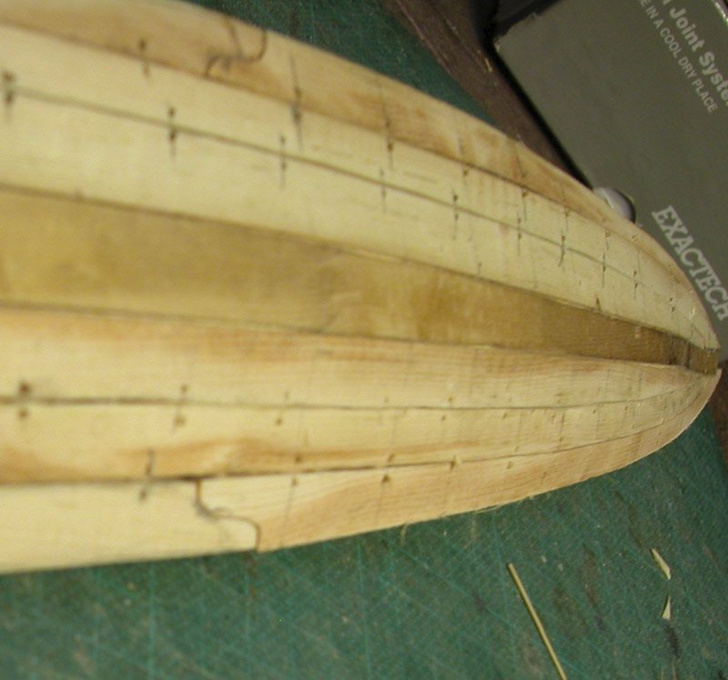
The hull is well underway. This the latest sheer plan of the vessel with figures for scale. Dick
-
Yes, the ship you are doing may be rounder than the Contarina 1 ship which I measure at about 4:1 but your vessel is probably earlier than Contarina. The Logonova wreck of about 1400 CE is also about 4:1. Dick
-
Steven, great to get you back cutting wood. That cross section looks vaguely familiar. Just a question or two: What will your length to beam ratio be and how will you calculate narrowing of the floors? Dick🙂
-
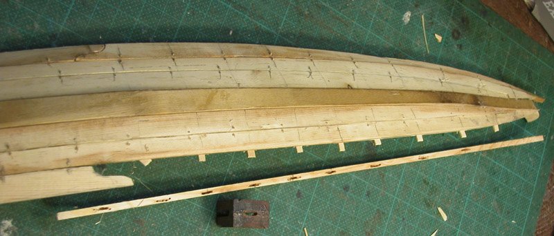
Thanks Steven. The next strake has a sigmoid scarf which were seen in ancient ships. I have used a simple jig to drill for the mortices. and pegged I think one more strake then do the turn of the bilge. Dick
- 142 replies
-
- 11
-
-

-
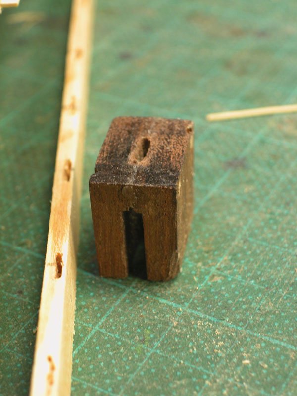
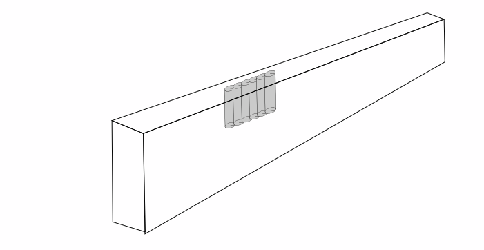
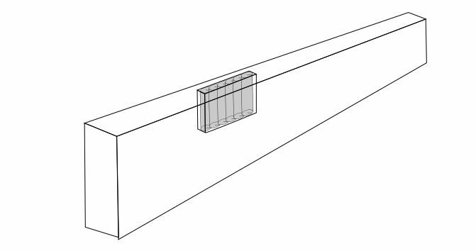
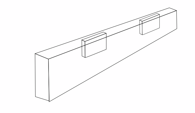
On the contrary the process is very basic and low tech. Cutting a continuous line in which to position the tenons is easy on a straight line or convex curve bbut not possible on concave edges. So these have to be cut individually. I tried burrs knives and even a high speed mill. None were satisfactory. I then realised that, in order to do these mortices in a rapid production line way, the ancient shipwrights must have had shortcuts. One thought is drilling a series of set depth holes and cleaning up with a chisel. I tried this and it works quite well and is quick. Next I will make a jig to do this reproducibly. Dick
-
These pics show the fittingof a strake using the pegged mortice and tenon technque. No glue is used. It is quite strong. Dick