woodrat
-
Posts
836 -
Joined
-
Last visited
Content Type
Profiles
Forums
Gallery
Events
Everything posted by woodrat
-
 Exactly, Roger. I allowed for that in this mast step by chamfering the slot for the mast foot so that the mast coould be"walked" into the slot an angle and then raised vertical. Cheers Dick
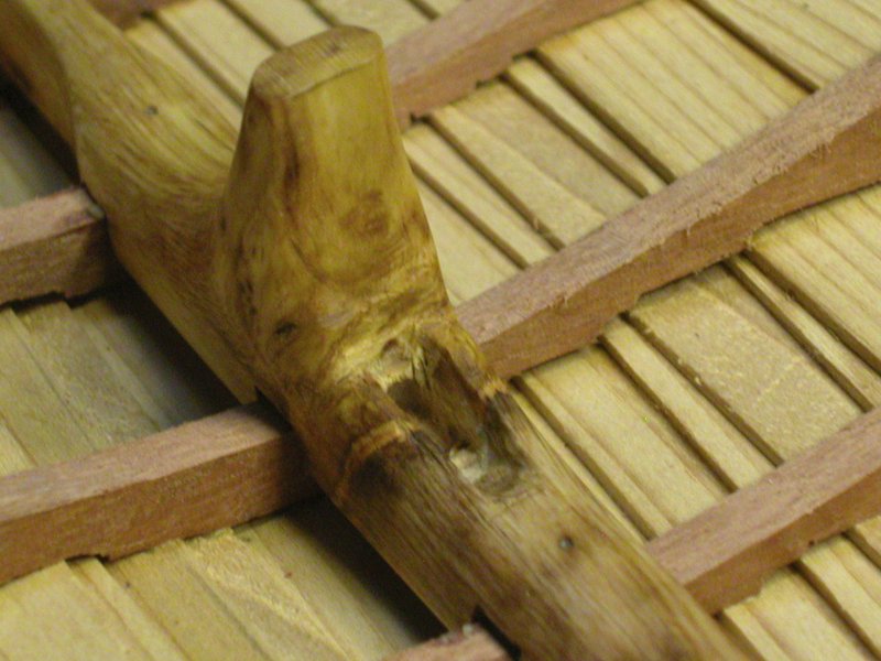
-
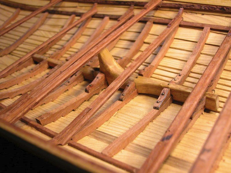
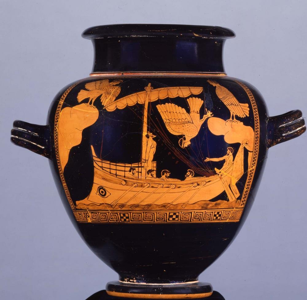
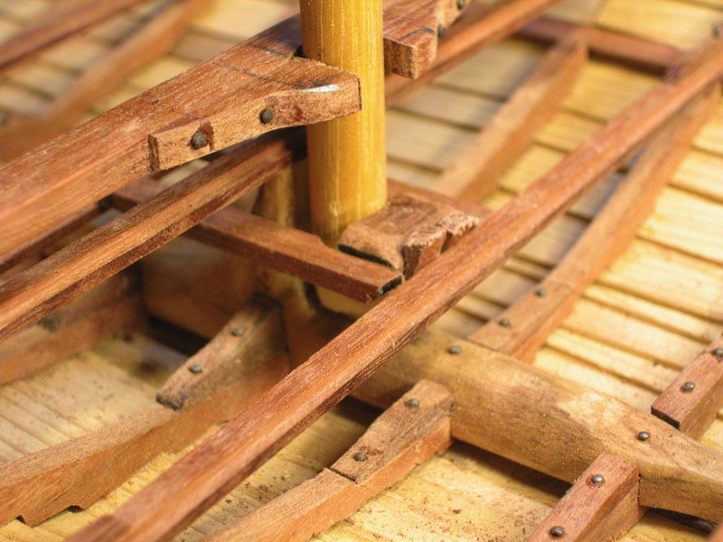
Ian, there are no pictures extant of this. The evidence is literary. When Odysseus was about to be tempted by Sirens, he commanded his crew to lash him to the histopede. The mast (histos), it is written, had been previously lowered and placed on its crutch (histodoke). So he cant have been lashed upright to the mast as has been shown in later red-figure pottery. It is likely that the histopede was an upright part of the mast step , much as is seen in viking ships (but taller) to which the stepped mast could be lashed. The following pics are from my hulc build. Dick
-
Eugene, I would not use pulleys, just wooden loops through which the ropes pass. There are no shrouds. There is evidence that at least in greek ships there were two forestays going to port and starboard forward bulwark which could act as sort of shrouds. There may have been a backstay. Also the mast step would include an upright post in front of the mast to which the mast is lashed when stepped. Beware of using modern deck fittings. Most ropes were secured around posts or bulwarks. Whatever you choose is right because nobody really knows. Remember this is the Bronze Age. Dick
-
I have given a description of minoan rigging in my mycenaean ship blog Cheers Dick
-
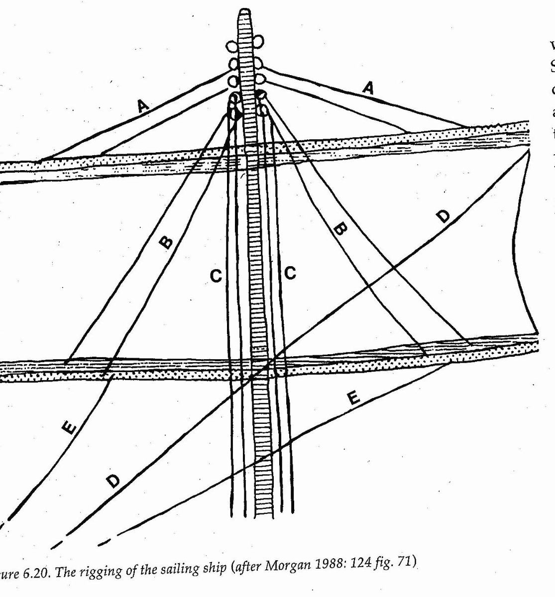
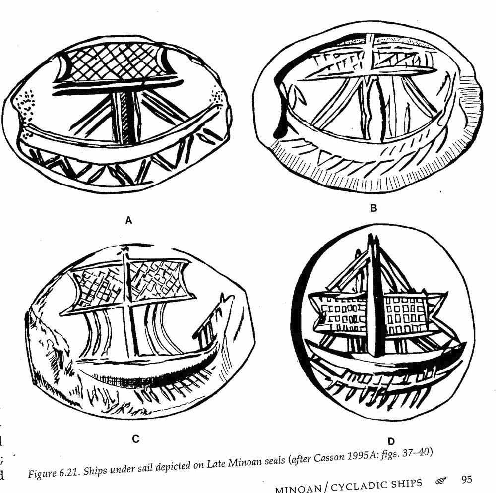
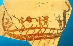
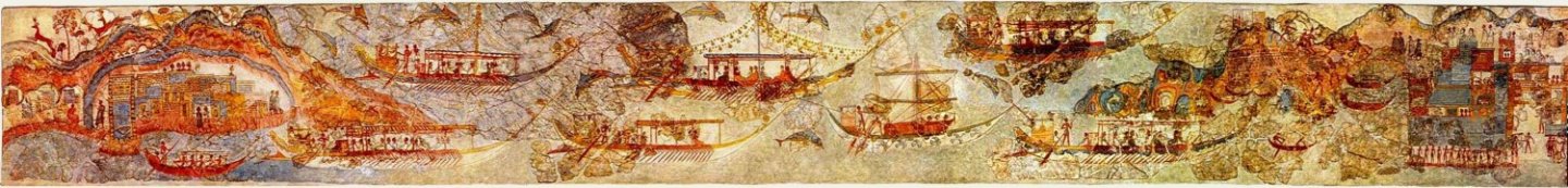
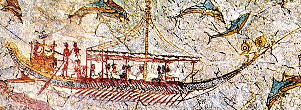
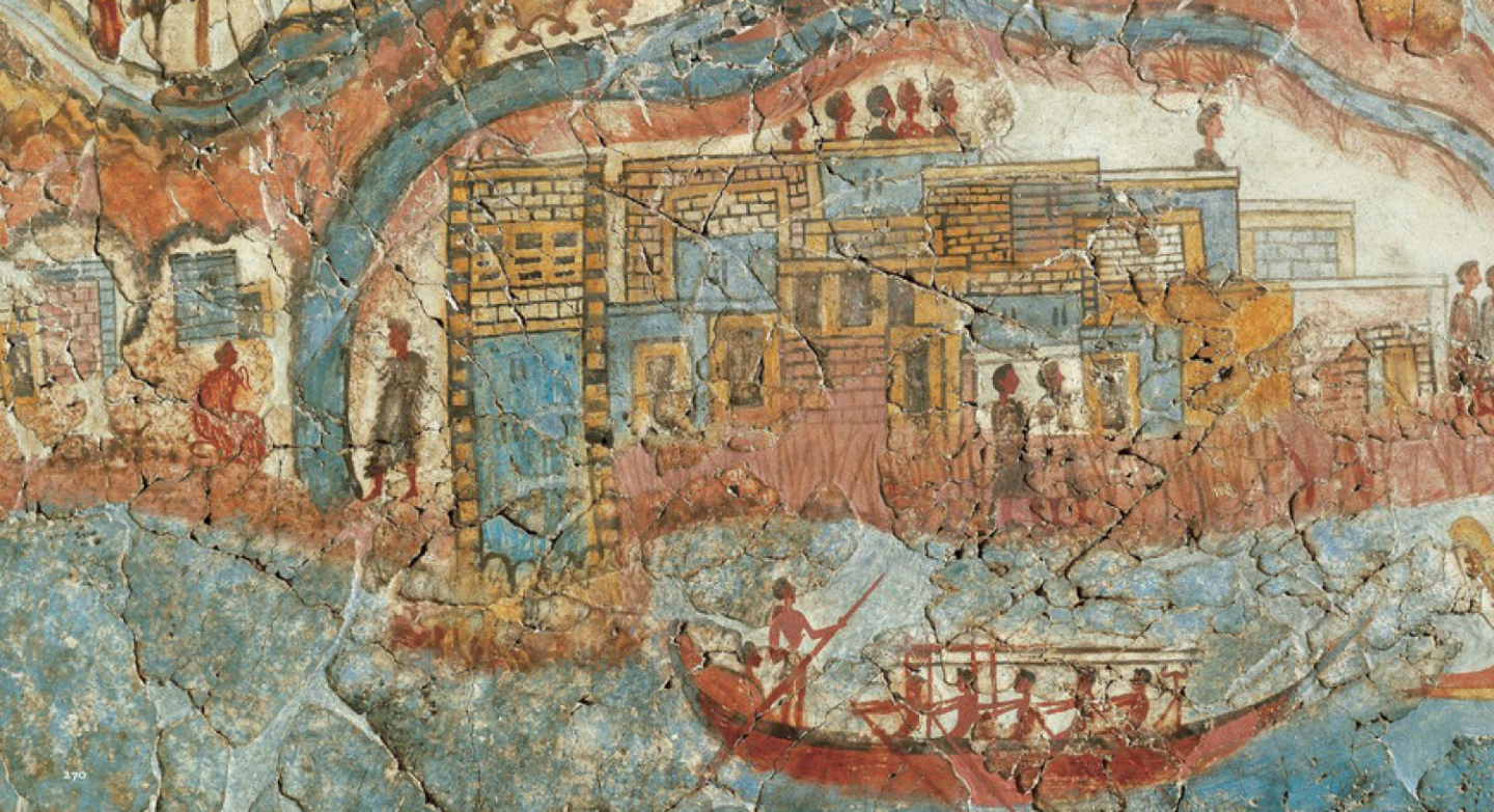
OK Eugene. The rigging of the Late Helladic vessels was most likely very different from that of the Middle Minoan ships such as you have attempted in your model. I will go into detail on Late Helladic rigging in a later post. from the Akrotiri ship procession frescoes The minoan vessels had a single mast with a square sail made of segments sewn together, material unknown. The sail was hung from a two or three piece yard with the pieces bound together maybe with leather rope. The foot of the sail was attached to a wooden boom. t Taken from Wachsmann originally from Morgan 1988 The yard and boom were controlled by a stack of loops at the masthead through which ropes were led to the deck. The use of stays and shrouds is conjectural. These seals give an impression of a hatched appearance to the sail segments. The sails may have been decorated for special celebrations. I hope this helps Dick


-
Nice to see a new member interested in the older ships. I will get back to you about the question of minoan rigging. Cheers Dick
-
I think there should be a rack either side of the quarter gallery to rack the pikes. Pulling them out of holes in the transom would be tedious in an emergency. Having them pointy things sticking out would certainly discourage boarding by the stern! 😁 Dick
-
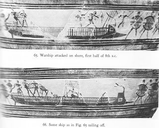
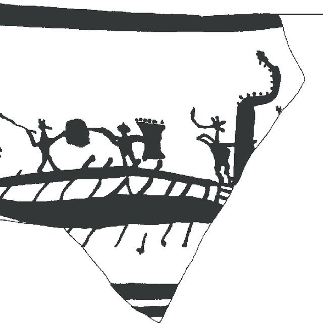
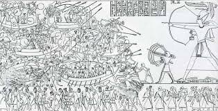
Thanks Steven and Druxey There are many competing theories e.g. the ladder represents an artistic convention with the plan view superimposed on the sheer view and representing frames. Or are the stanchions at the side of the bulwark or internal to it supporting a war deck? No one knows for sure. Some reconstructions show a spindly structure supporting just a cowhide pavise (e.g. Argo reconstruction discussed later). Others opine that the stanchions were strong enough to support not only a war deck but also rowers benches if the galley was rowed from the upper station. I will decide once I have made the wooden hull. There are clues from the representations from the Geometric period which followed the Late Helladic that show warriors legs seen through stanchions and apparently standing on what might be the lower rowers benches. From Casson: Ships and Seamanship etc Other geometric galleys show the they were either rowed from upper or lower positions (or maybe both) From Casson: Ships and Seamanship etc However, the last picture is interpreted by Landstrom as owing the port and starboard rowers placed one above the other. I dont ascribe to this. There are enough pictures of geometric galleys showing warriors gallumphing along a raised war deck to satisfy me that the superstructure was strong . If so, the hull must be deep enough to compensate for the top-heavy superstructure and the gallumphing warriors. Grapnelling a ship's mast or rigging and capsizing it is well shown in the Medinet Habu bas reliefs and seems to be a favoured technique of sinking ships in the era before the invention of the ram. So top heaviness was always on their mind! From Casson: Ships and Seamanship etc Cheers Dick
-
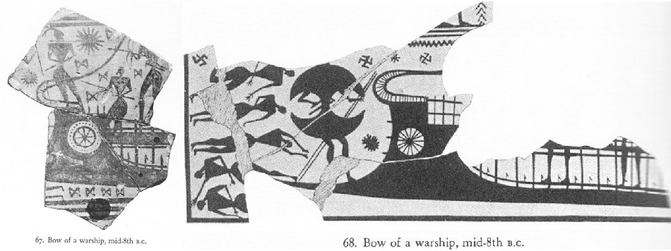
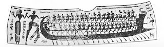
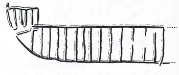
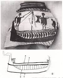
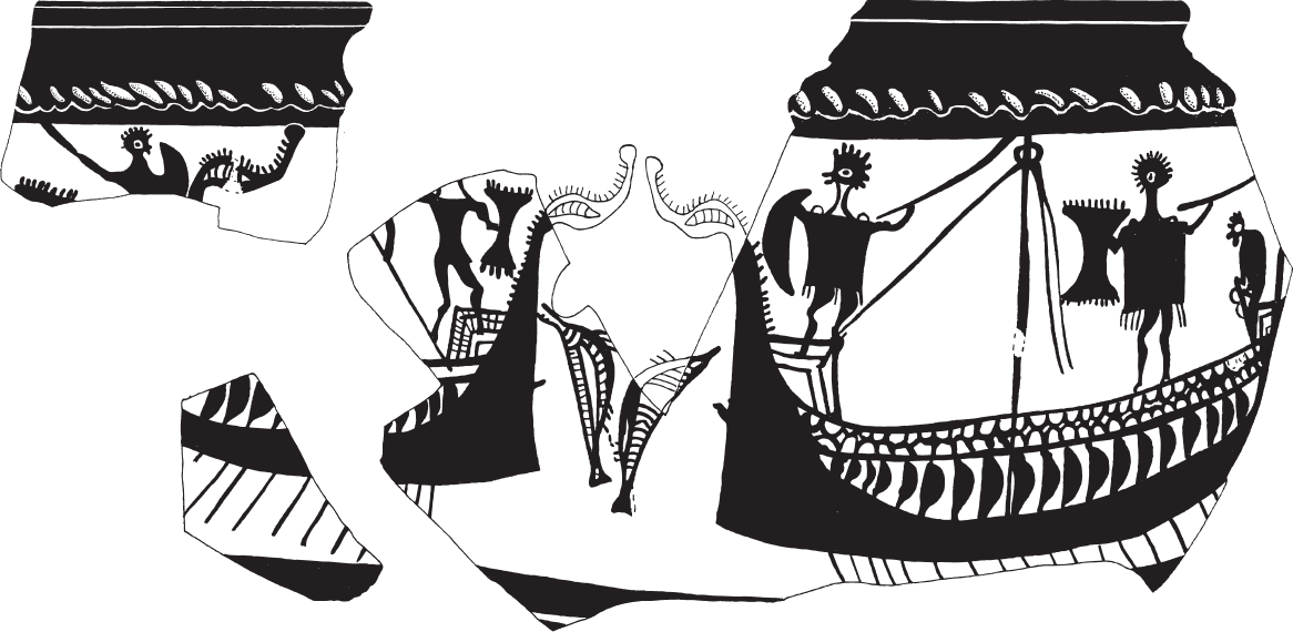
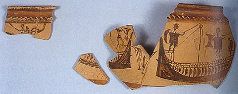
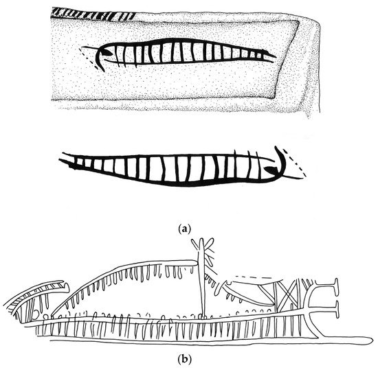
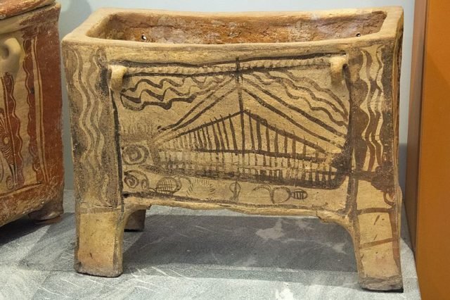
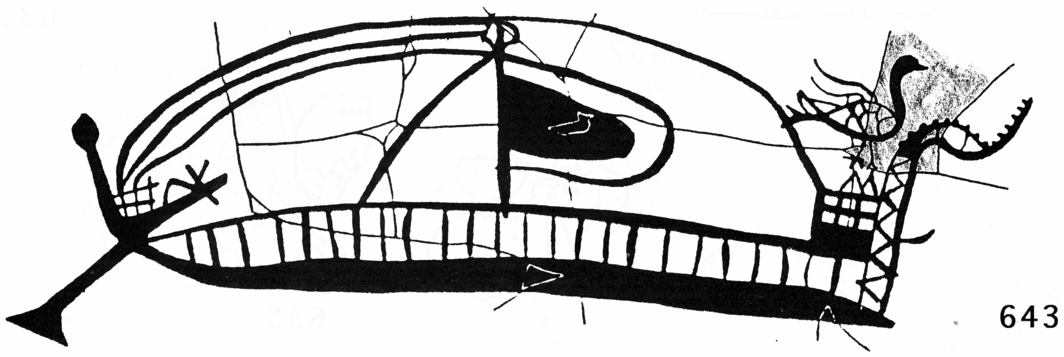
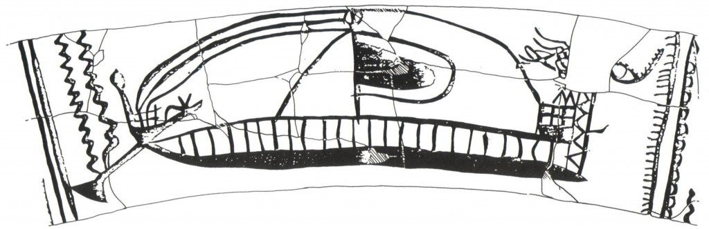
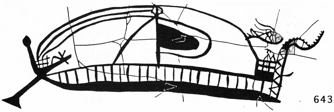
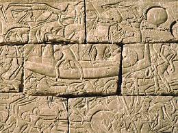
The Mycenaean Pottery Shards The Kynos Ships. There are some common elements seen in the depiction of Mycenaean vessels on pottery bits. The most striking is the ladder-like appearance. In some cases, the vessels have been simplified to the point that all is seen is a ladder.http://www.salimbeti.com/micenei/ships.htmFrom S. Wachsmann : Seagoing Ships etc At Pyrgos Livonaton in Central Greece a site has been excavated and identified as Kynos, mentioned in the Iliad. Quite a number of pottery fragments showing ships, parts of ships, warriors and clay ship models has been found. The most complete of the depictions is the Kynos Ship A. From S. Wachsmann : Seagoing Ships etc http://www.salimbeti.com/micenei/ships.htm This lacks only the figurehead and sternpost decoration. The hull is subtly crescentic but with a sturdy vertical stem post and a curved stern. The steersman is depicted on his stern platform holding the loom of a steering oar. Betwixt the stem and stern is a band with the appearance of bubble-wrap. This has been interpreted as a bulwark faced with cow hide (seen in other depictions commonly e.g. on shields). Nineteen vertical partitions are seen between the bulwark and the hull with half-moon shaped silhouettes attached. These latter have been interpreted as the chests of the oarsmen at the end of their stroke. The partitions are likely to be stanchions supporting the deck superstructure. The heads of the oarsmen are thought to be hidden behind the cow-hide bulwark. Atop a lightly built forecastle postures a feather helmeted warrior and a further warrior aft of the very sketchily indicated mast. This depiction may represent what Homer referred to as a pentikontoros (25 oars a side) in his epic. It could equally be a triakontoros (15 oars a side). The similarities to the Medinet Habu ships are evident . Kynos Ship C' http://www.salimbeti.com/micenei/ships.htm Kynos Ship C shows well the bird shaped figurehead with a sharply up turned beak commonly seen on these ships. The oars in this case are unmanned, presumably they grabbed their weapons and were in the process of smiting. Interestingly, the oars are seen extending above the bulwark. Does this mean the vessels could be rowed from two stations, above or below the bulwark according to need? This is seen on later shards from the eight century BCE. A painting on a sarcophagus from Gazi in Crete (in Iraklion Museum now) shows a roughly drawn ship of this era. The ladder effect is prominent. From Tragana near Pylos in the Peloponnese comes a largely complete ship with 24 stanchions presumably a pentikontoros. It shows a bellying square sail and an interesting steering oar. The bird-shaped figurehead is again seen and this time has an additional figure ( half missing) behind the figurehead which may be another bird. Note also the small projection of the ?keel and another sharp projection halfway up the stempost The rear bird is speculative, it might be a fish? Clay models next Cheers Dick
- 142 replies
-
- 10
-

-

-
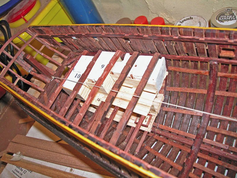
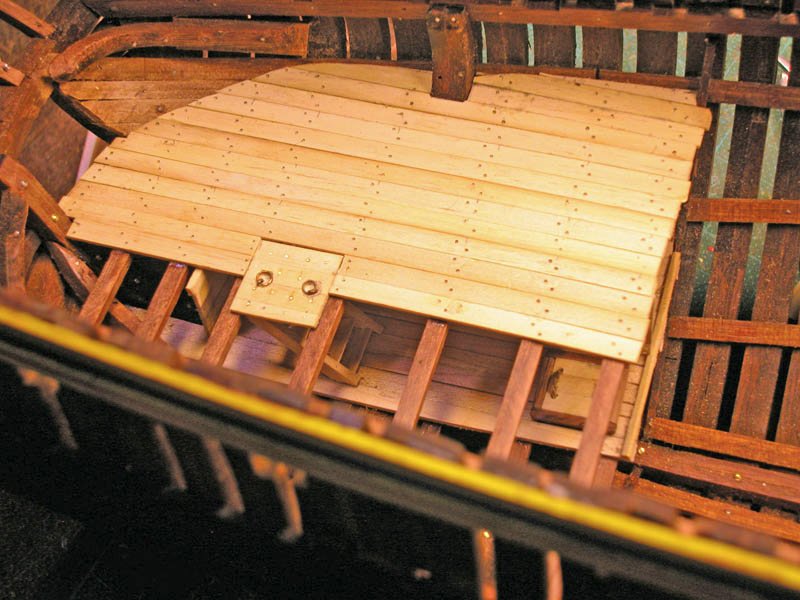
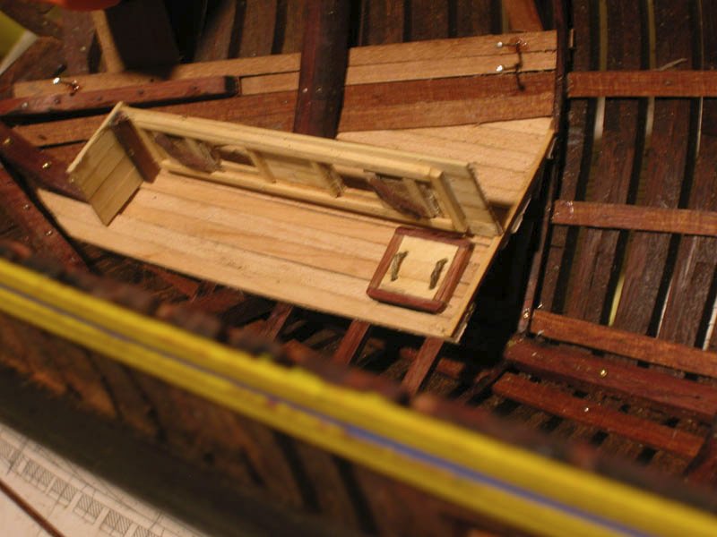
This shows the storerooms beneth the main deck beams. This would include the bread room, vegetable locker, spirit room etc. Only the port half is shown. Sliding hatches allow access to some of the stores. I made balsa wood blanks to ensure fit of the cabin walls beneath the deck beams and constructed the walls around them. Cheers Dick
-
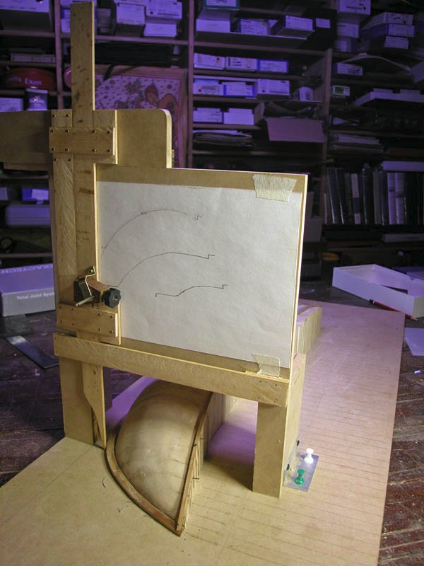
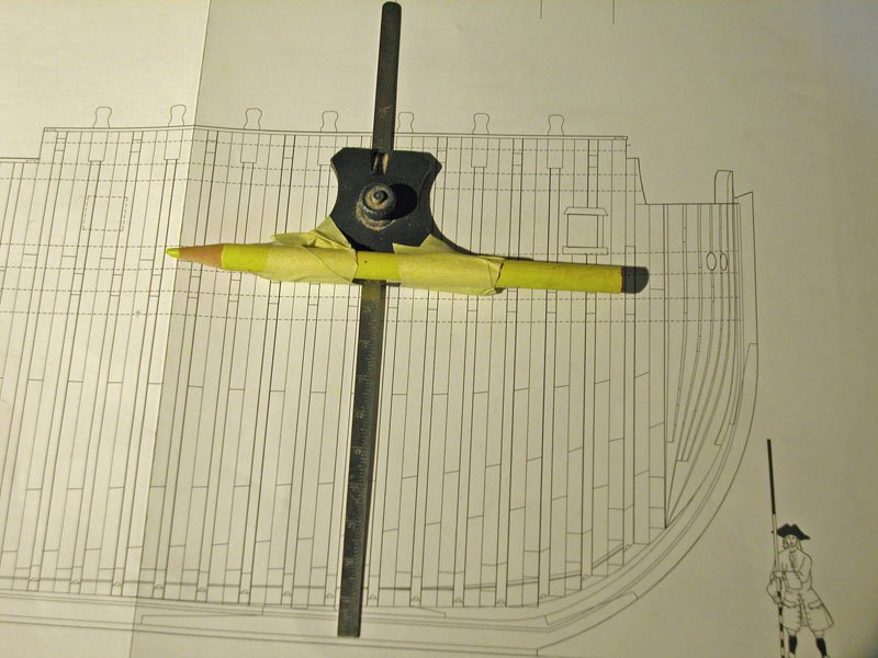
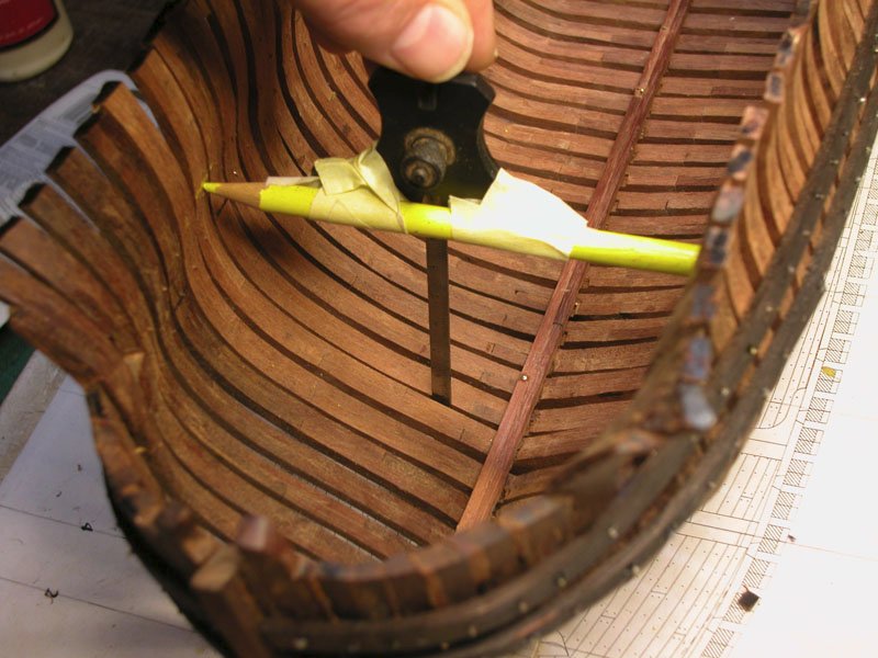
Ian. I have used this device a couple of times to take sections off half-hull models and it works well. It is relatively easy to make but you need ball bearings on the cross -slide to reduce friction and jerking movement. Cheers Dick
- 536 replies
-
- 5
-
-
-
- Quadrireme
- radio
- (and 1 more)
-
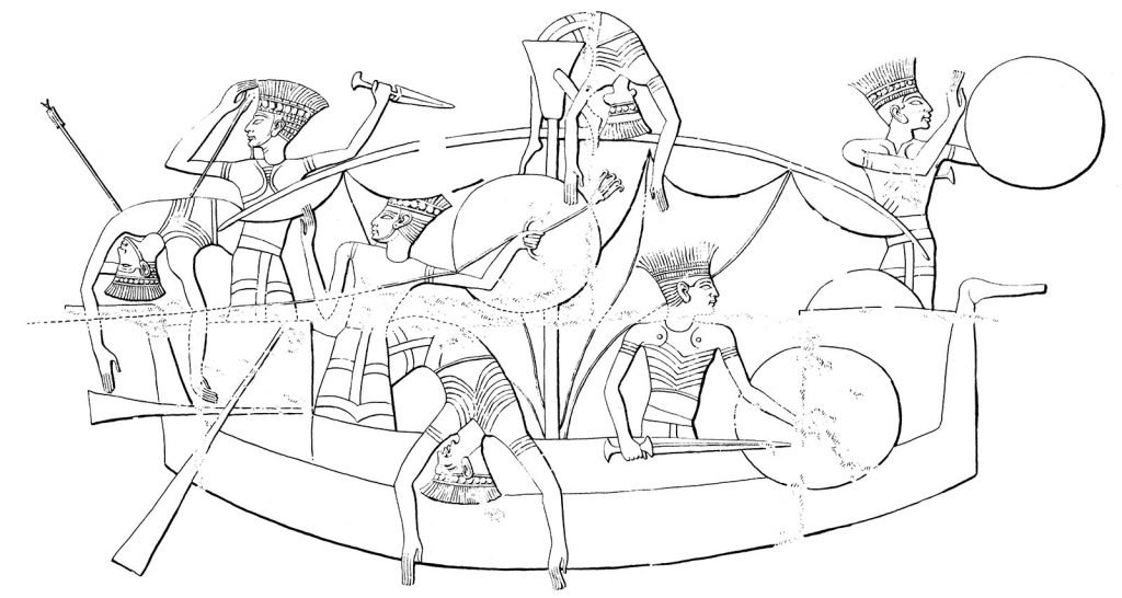
Thanks Ian, Chuck and Steven for your comments and support. I will of course discuss some of the antecedents of mycenaean craft as follows 1. The Iconography Most of the images I will use will come from pottery shards which are confidently dated to the Late Bronze age. Some pottery from the Geometric period will be cautiously referenced. I will not refer to evidence from the Middle Bronze Age as the nature of shipping was markedly different then as evidenced by the remarkable wall frescoes from the minoan island of Thera. These vessels were crescentic and symmetrical in hull shape and propelled either by paddles or oars and with a mast with a square, boom-footed sail very much as seen in Egyptian and syro-canaanite ships of the era. There are similarities with the Dahshur boats and the Royal Ship of Khufu but the mycenaean war galley had little in common with these vessels of an earlier era While I am on the subject, I intend to use the Egyptian evidence sparingly. Also, some will note my lack of reference to Landstrom’s books (which I Iove looking at) because I think his reconstructions may influence me too much. Many of you will be aware of the Late Bronze Age bas-reliefs carved and painted onto the walls of the mortuary temple of Ramses III at Medinet Habu. These depict in graphic detail a battle between the maritime war vessels of Ramses III and a fleet of foreign peoples known as the Sea-Peoples. Much has been made of the Sea-Peoples as a possible cause of the Late Bronze Age Collapse but there is only peripheral evidence for this and the present consensus is that they were an indication of major population shifts in the Mediterranean basin and were one of a number of factors such as climate change, famine, earthquakes and war which created a “perfect storm” and led to the demise of the Myceneans, the Kassites, the Hittites, Mitanni and nearly the Egyptian civilisations of the early twelfth century. For a very readable and logical account of our knowledge of this collapse, may I recommend Eric Cline’s book 1177: The Year Civilization Collapsed. There are also some YouTube clips by him which are useful. The ships represented at Medinet Habu have similarities to the mycenaean war-galley and indeed some have included the Mycenaeans in the Sea-Peoples but this is controversial (the list of Sea-Peoples includes the denyen = ?the Danaans of the Iliad). (stop press: the discovery has been announced of the worlds largest ancient shipyard in 2023 on the island of Dana, located off the coast of Mersin province in the Mediterranean region by turkish archaeologists from Selçuk University . This has led to the possibility that the Denyen (danaans) of Sea-peoples fame may originate from this area.) https://arkeonews.net/underwater-archaeologists-discovered-worlds-largest-and-oldest-ancient-shipyard-on-dana-island-turkiye/ The Sea-Peoples ships are rowed, have a crescentic hull, fore and stern-castles and bird heads on both the prow and stern facing outward Some speculative reconstructions have been made of the Sea-Peoples ships based on these bas-reliefs but caution is required. The carvings were done by royal Egyptian artists and have doubtless been influenced by the artistic conventions required of them and inevitably some inaccuracies in scale, number of rowers and structure may have occurred. Nonetheless, these images are a very useful first step in resurrecting the mycenaean war galley to which they have some resemblance. Please see Shelley Wachsmann’s excellent monograph for a full discussion of the Medinet Habu reliefs. The distribution of corpses about the overturned ships give some indication of the nature of the ships’ superstructure The next section will discuss the Late Helladic pottery shards and clay models Here is a limited bibliography: Shelley Wachsman: Seagoing Ships &Seamanship in the Bronze Age Levant. Texas A&M. 1998 Lionel Casson: Ships and Seamanship in the Ancient World. Princeton University Press. 1971 Paul Johnstone: The Seacraft of Prehistory. Routledge Kegan and Paul. 1980 J R Steffy: Wooden Ship-building and the Interpretation of Shipwrecks. College Station. 1994 John Morrison (ed.): The Age of the Galley. Conway’s History of the Ship. 1995 Basil Greenhill: Archaeology of the Boat. London. 1976 Dick
- 142 replies
-
- 10
-
-
-
Perhaps the most important event to shape the Middle Bronze Age was the demise of the so-called minoan civilization of Crete. Minoan is a term pulled from the rather creative brain of Sir Arthur Evans, the excavator and popularizer of the Palace of Knossos which he, on the basis of no evidence, called the Palace of Minos. The people he named the minoans were an expert sea people who were known to have traded extensively, especially with Egypt (who record the cretans as the keftiu). The demise of the minoan palace-based civilisation is poorly understood and probably was not sudden. The eruption of the volcanic island of Thera in about 1600 bce may have played a part in this. Certainly, the palaces of Crete were not destroyed by a monster tsunami, as is popularly depicted, but it may have destroyed the minoan war fleet and left the palace-based civilization open to opportunistic takeover by their erstwhile trading friends the mycenaeans. The Late Bronze Age (Late Helladic when applied to Greece) is regarded as that period between the fall of the minoans (1600 bce) and the catastrophic collapse of the Bronze Age civilizations in the early 12th century bce. The mycenaeans, also known as achaeans (and likely corresponding to the ahhiyawa of the Hittite records), traded extensively throughout the Aegean Sea and the Levant. They were also likely involved in piracy and freebooting including the famous siege of Troy which may have occurred in the Late Bronze Age and was later celebrated in oral performance by whoever Homer was (or were). In any case, the mycenaeans were based in the Peloponnese and what later became Greece during the Iron Age. By fair means or foul, they became the heirs to the palace civilization of Crete and together with the syro-canaanites of the Levant took over the minoan trade networks. The mycenaeans were known as deep-sea traders but they also were more war-like. It is likely to the mycenaeans that the next revolution in sea-warfare is owed, namely the large, rowed war-galley which became the raiding longship of the age. This is not to say that the mycenaeans invented the concept but they certainly popularized it and brought it to a level of prominence and sophistication which led to its evolution into what became the most feared weapon of war of the Age of Bronze. These in turn were to further evolve during the Iron Age into the battleships of the Geometric and later Attic periods of Greece, the biremes and triremes. It is my intention to build as convincing a reconstruction model of a Late Helladic war-galley as I can with the very limited and confusing contemporary evidence available from paintings on pottery, graffiti, carvings on seals and small clay or lead ship models which have survived the ages. It is not my intention to use other reconstructions or modern artistic representations of these vessels but to sail unescorted into uncharted waters. I will, of course, be greatly guided by the archaeologists and historians whose knowledge of the period is vast but all the while recognizing the controversies which abound in their literature. Where possible I will try to use construction methods which were known to be extant at the period we are discussing. I may come up with the occasional idea of my own When I carried out my “reconstruction” of the mediaeval hulc vessel, I found that the method of construction greatly influenced the final shape of the hull and it is likely that the same will occur with this build. I have no academic axe to grind and really it is immaterial to me whether this model meets with academic approval. I claim all my mistakes as my own but welcome them being pointed out. No wrecks of any of these war-galleys or similar vessels from the period have survived. The only wrecks of relevance are a couple of trading vessels such as the Uluburun ship found off the coast of Turkey which give some clues to keel and plank configuration. But all the rest relies on the surviving imagery on fragments of pottery and crude models. I hope you will bear with me as I blunder through this putative reconstruction and, of course, I would like to encourage any MSW members to contribute. There is a vast body of knowledge in MSW which I hope will protect me from the more egregious errors. So, please help me if you can. Dick
- 142 replies
-
- 18
-
-

-
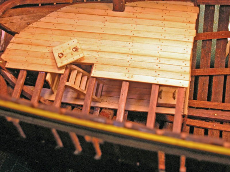
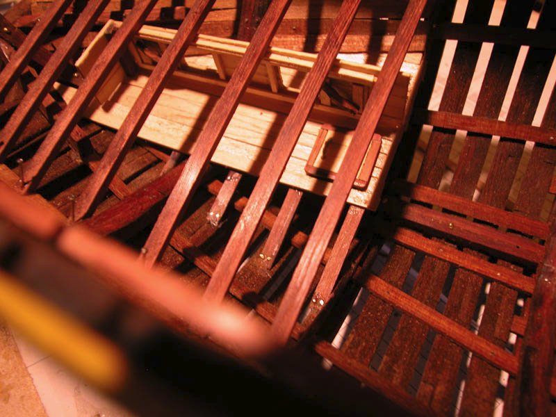
The next level of deck has been installed as well as the flush scuttle above the powder store. This deck is level with the sill of the loading port in the port stern timbers (used for loading the spar spars for the expedition. To allow for loading of spars, the store cabins on this deck are demountable. cheers Dick
-
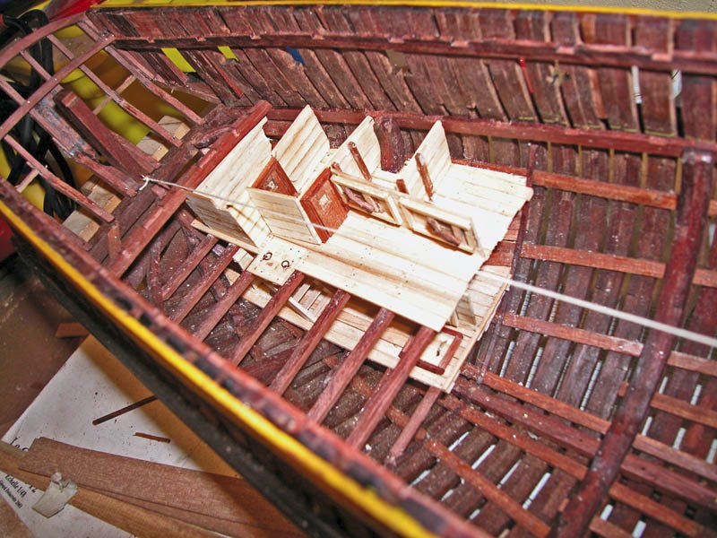
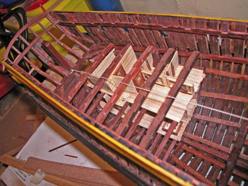
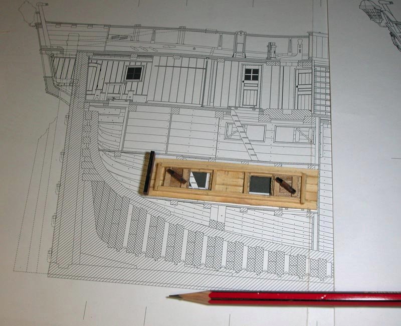
I have decided to install cross sections os the lower deck partitions. This the powder room, the lowest store. As this is a merchant vessel, it would probably double as a filling room and be accessed from a flush scuttle in the deck above. No iron fittings were allowed and all nails were of copper. A small scuttle in the floor would allow powder spills to be swept out to avoid risk of explosion. It is a good exercise to build the s storerooms as it made me research more . this shows the sliding panels for distribution of filled cartridges. I assume that the powder barrels were loaded through the scuttle above. I have not shown the light alcoves which separated the lanterns from the powder store . These would have been in the starboard wall. These would exclude flame from the store. The beams for the deck above are in place. Dick
-
The stern timbering is largely complete and the upper deck clamps are in place. Consideration now needs to be given to the orlop and false decks. As this vessel is meant to portray the ship at the time of its West Australian visit, augmented armament has been installed as well as an extended false deck to provide additional accommodation below the main deck. Cheerio Dick
-
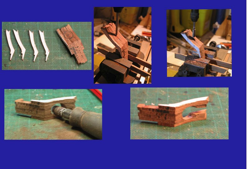
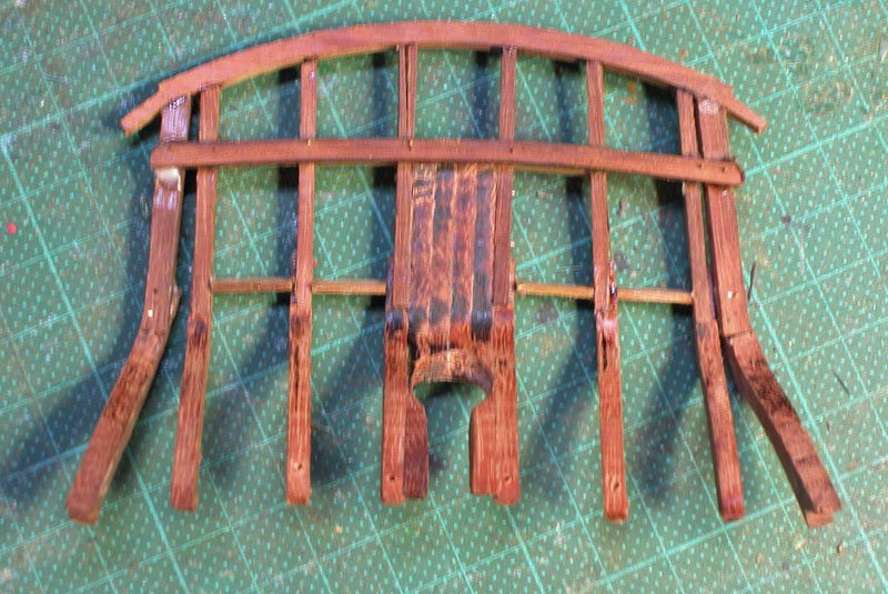
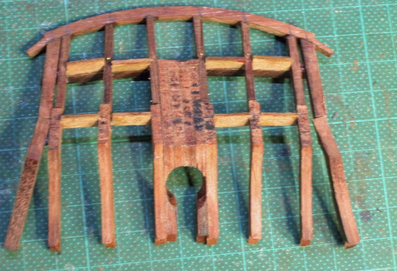
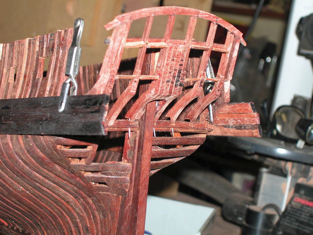
Lots of fun doing the stern timbers. This is the key shaped opening for the sternpost and rudder head being cut using a mill and finishing of with the rotary tool The stern timbers temporarily in place The stern module front and back sort of in place but not yet fixed. The window frames need work. Cheerio Dick
-
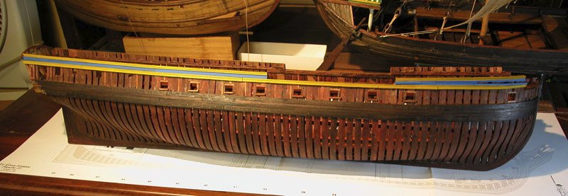
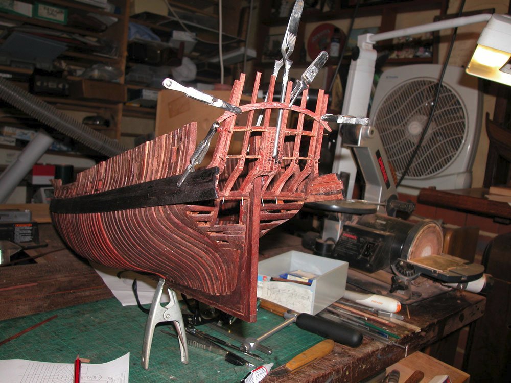
Thanks, Druxey. I have now cut the gunports and trued the frames. The wood (jarrah, a west australian hardwood) has been oiled with orange oil. This brings out the red of the timber but this will darken with time. Not many models are made with jarrah (if any) but the replica of Cook's Endeavour, which was built in Fremantle West Australia and is now in Sydney, was built using jarrah and therefore will last forever. Cheers Dick
-
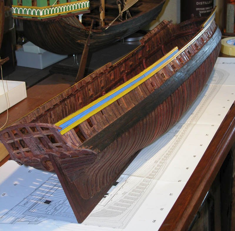
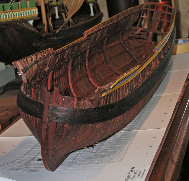
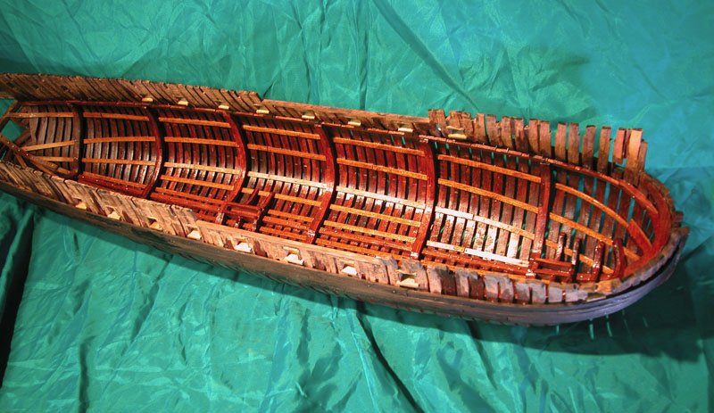
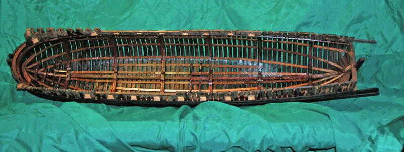
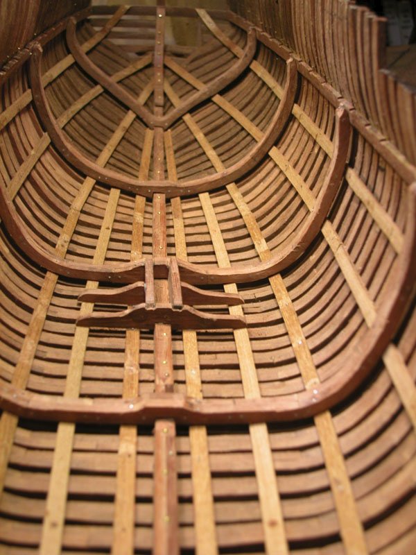
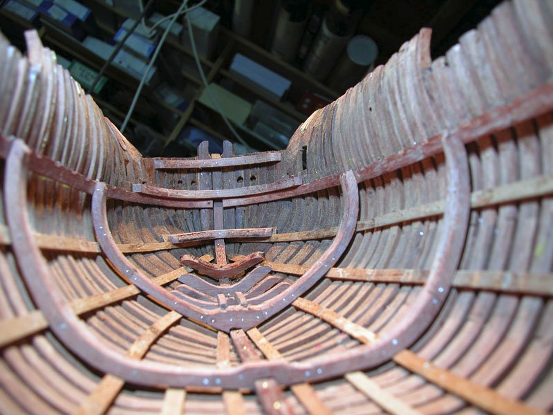
More progress on the hull: The ceiling has been indicated by a number of longitudinal strakes The athwartships futtock and floor riders have been installed. Main deck clamps in place Breasthooks installed Fore and mainmast steps in place Looking forward Looking aft Stern timbers promise to be a challenge! Cheers Dick
-
Steven, I just realised that I have been remiss in not commenting on the wonderful nef you have reconstructed. The figures add a good impression of the scale and the realities of working a vessel with just wind and muscles. I hope that the trumpeters were expected to pull on a rope too! Splendid work and I love the barrels. What about putting it in a diorama? Dick😃
-
ancre Le Gros Ventre by ChrisLBren - 1/36
woodrat replied to ChrisLBren's topic in - Build logs for subjects built 1751 - 1800
Welcome back. 1/36 scale. You must have a bigger bench than me. Very neat work. Dick -
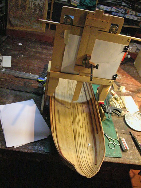
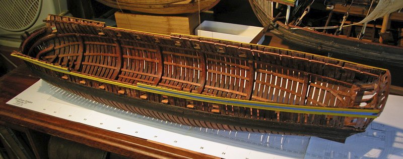
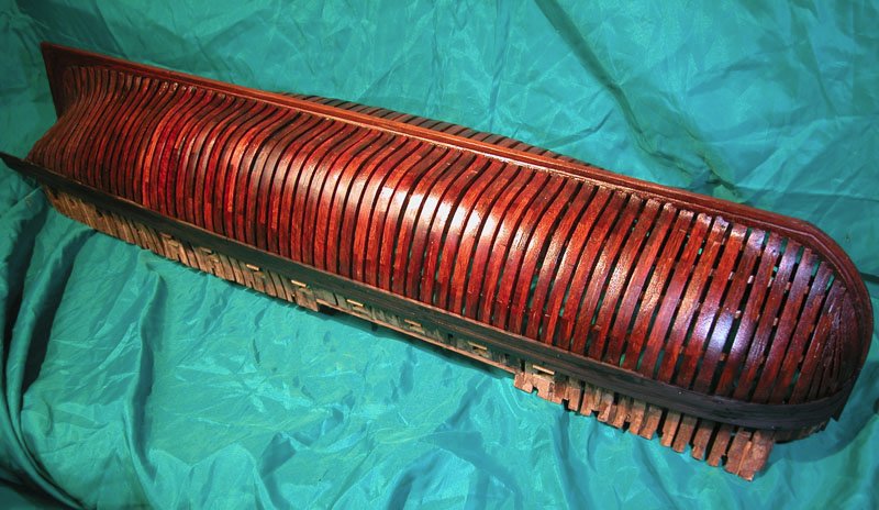
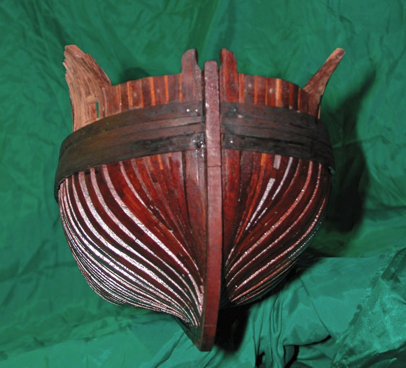
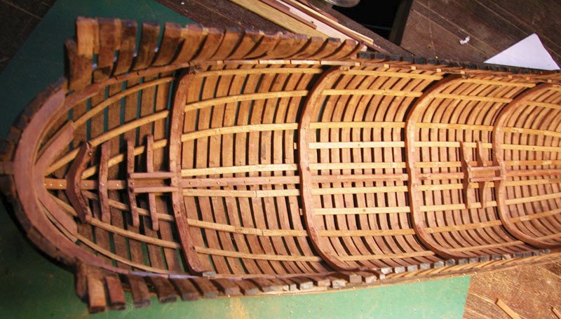
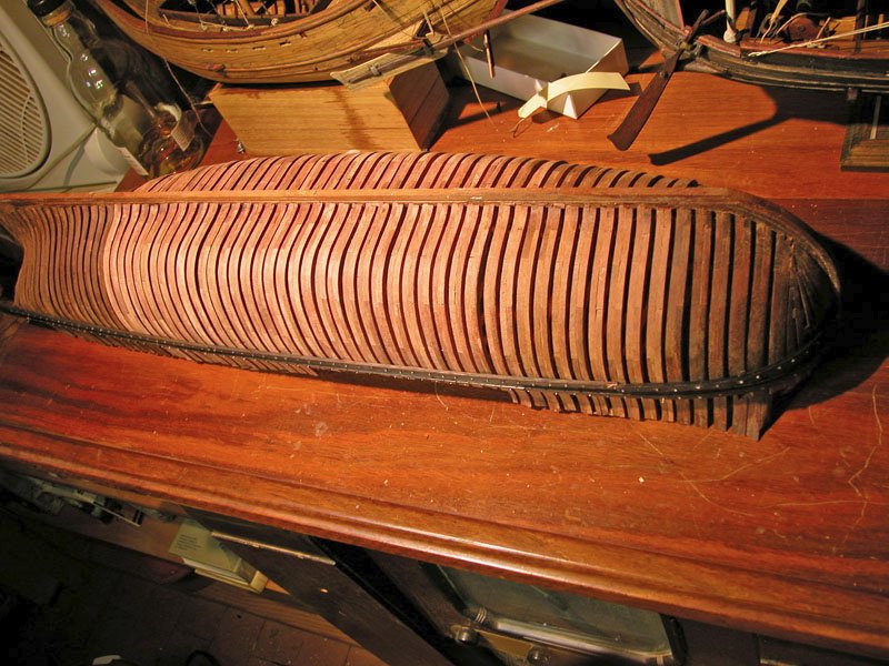
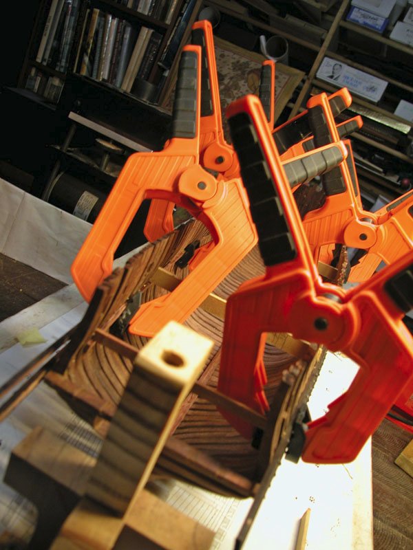
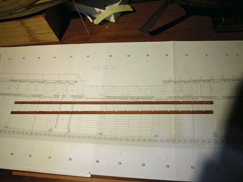
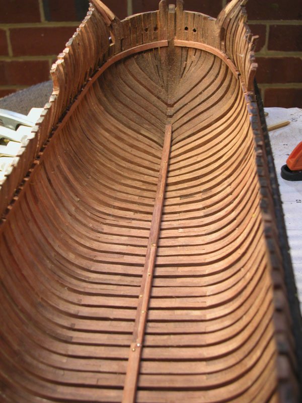
Thanks, Steven. I was feeling a mite guilty because the thing sat in its building frame for years glaring balefully at me from the back of the workshop. It's now starting to look like a ship and hopefully a happy one! Here is the view from below out of the frame It was necessaery to measure, remeasure and re-remeasure the position of the deck clamp as this is the most vital for all other measurements. Also the deck must end up horizontal. fortunately with the building frame holding the hull strongly in a vertical position, it was possible to measure directly off the plan and transfer the measurement directly to the frames The main deck clamp ready for insertion The main deck clamp fixed in position and horizontality checked The main deck clamp installed Cheers dick
-
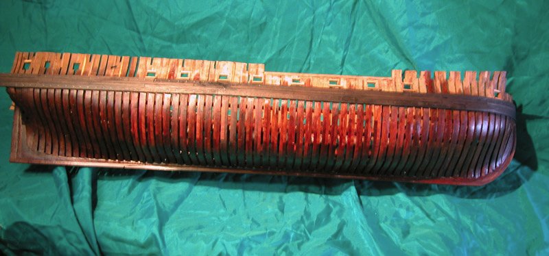
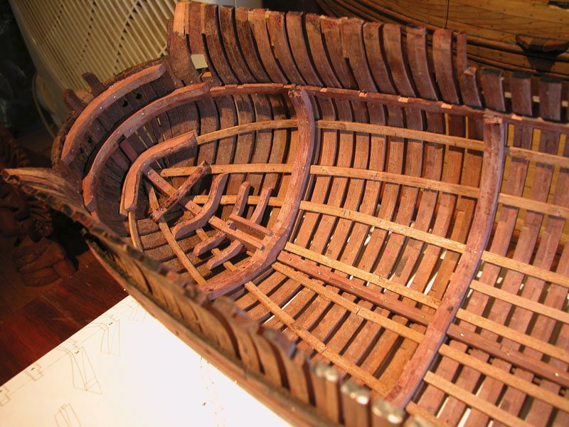
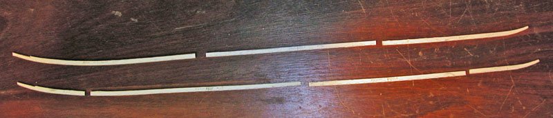
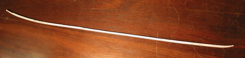
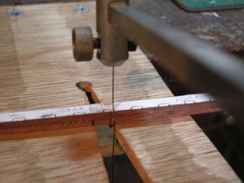
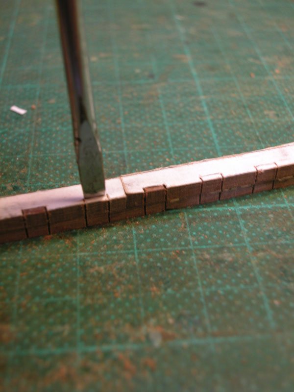
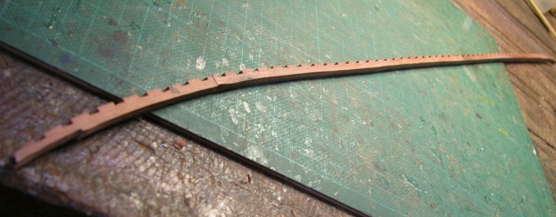
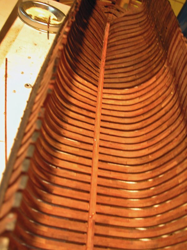
The construction of the keelson: The keelson is made from several overlapped pieces Which are joined Mortices are cut with a jeweller's saw. I find this safest. and chisel (made from a small screwdriver) Keelson in place Framed hull taken out of building jig (but only for a little while. I like to leave it in the jig until all stabilising longitudinal structures are in place) Cheers Dick
-
Thanks for choosing this beautiful topic. I would imagine this beast would be paddled not rowed because of its low freeboard and this fits with the maori waka or war canoe concept as Louie da Fly suggests. Do you think this would have been coated in pitch? But the grain of the wood is pretty. A lovely piece it will be. Dick🙂