woodrat
-
Posts
836 -
Joined
-
Last visited
Content Type
Profiles
Forums
Gallery
Events
Everything posted by woodrat
-
 I have seen many more imaginary and fanciful "reconstructions" of famous ships that definitely existed, such as Santa Maria and the Golden Hind, but never in the strange manifestations offered by many kit manufacturers. I am at least honestly guessing at what may have been and at the end of the task will have an attractive vessel on the mantle-piece. As has been stated in this log, experimental archaeology is its own justification and can shine light on the past that shipwreck retrieval archaeology cannot always achieve. As an example of what experimental archaeology can achieve, I would point out your excellent reconstruction of the byzantine dromon and encourage others to take on such projects which are outside the mainstream of ship-modelling. Do we really need any more imaginary models of famous ships? Grumpily yours Woodrat
- 186 replies
-
- 3
-

-

-
- keelless
- reverse clinker
- (and 4 more)
-
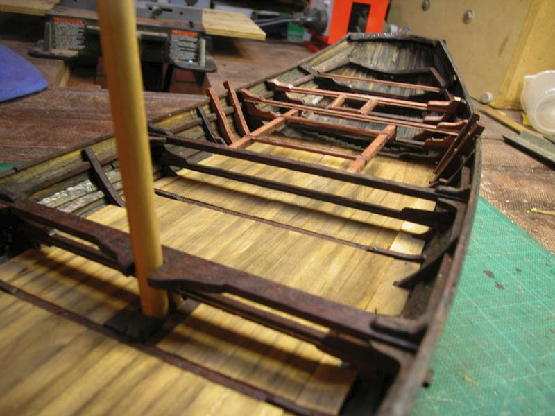
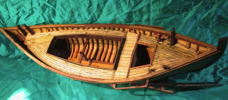
The framing for the upper decks and hatches. The central area around the mast is for cargo and equine transport. Gangways will be installed. Looking aft from bow Looking forward from stern stern showing the lower halyard block Cheers Dick
- 186 replies
-
- 5
-
-
-
- keelless
- reverse clinker
- (and 4 more)
-
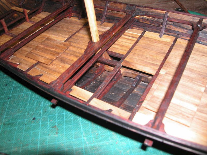
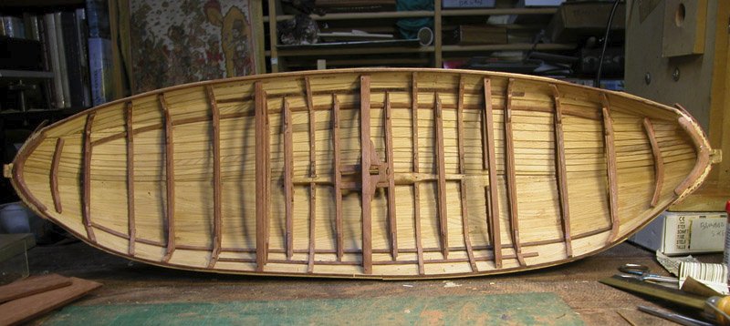
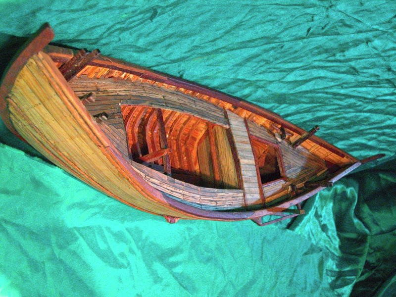
The lowest deck has been fitted. I have done this in removable panels. This would have been necessary to get access to the bilge for cleaning and repairs, especially if transporting horses. Cheers Dick
- 186 replies
-
- 6
-
-
-
- keelless
- reverse clinker
- (and 4 more)
-
Why,sometimes I've believed as many as six impossible things before breakfast.
- 186 replies
-
- 3
-
-

-
- keelless
- reverse clinker
- (and 4 more)
-
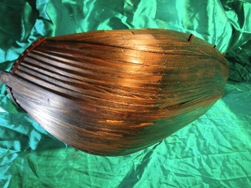
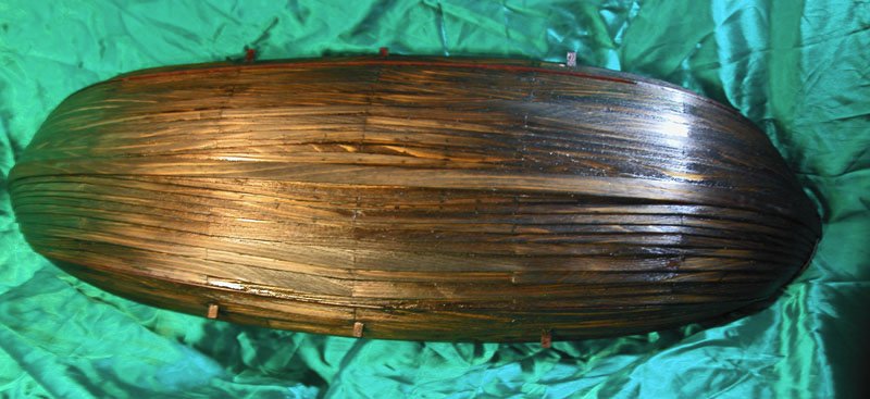
Framing complete and the hull is stained to imitate the likely colour of the beast. I hope you approve of the effect Cheers Dick
- 186 replies
-
- 10
-
-
-
- keelless
- reverse clinker
- (and 4 more)
-
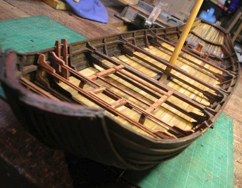
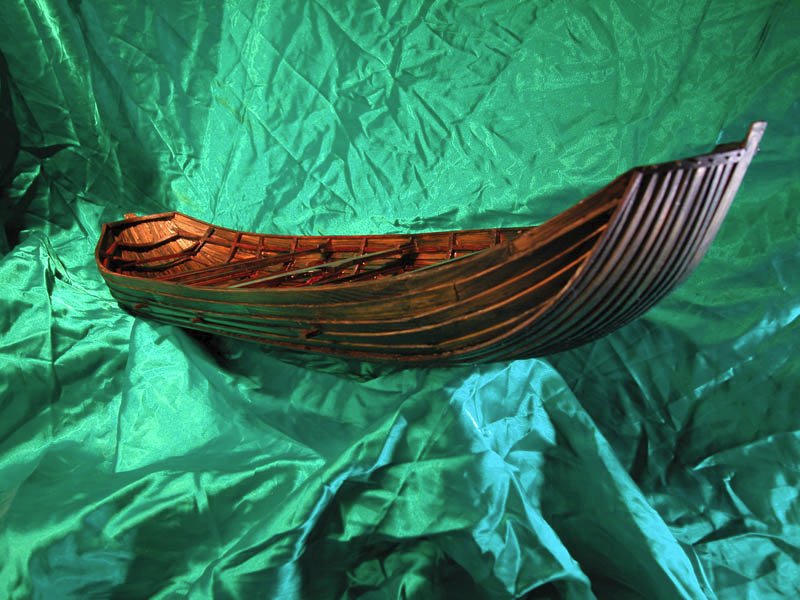
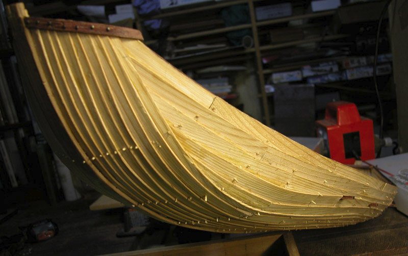
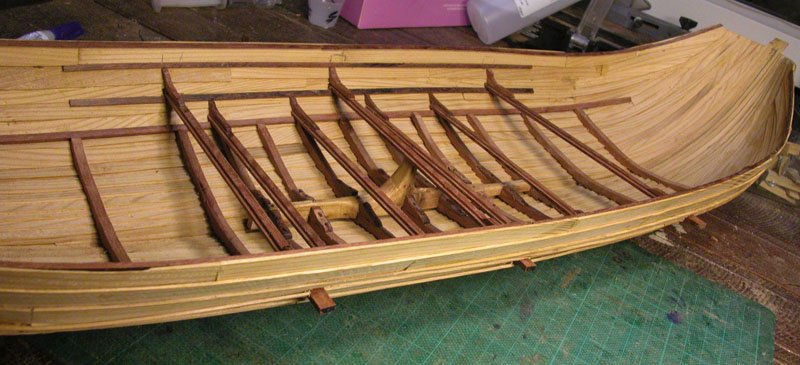
Hull framing nears completion with all frames trenailed to shell. The decks will be next. I plan to have a central cargo area which could transport horses if required. The scandinavian influence is obvious but the barge-like shape of the hull would increase cargo carrying capacity. The reverse-clinker leads to an increased resistance to leeway which makes it less necessary to have a deep keel. The side rudder however will need to be wide and deep in the water to add more lateral resistance. Also note that the reverse clinker creates a channel in the midline beneath the keelson where water can pool. There is no need then for limber holes in the frames and less likelihood of rot. Evacuation of water is simply done either by bailing or a log pump. I think I will install the latter.There is plenty of room beneath the keelson for water to move side to side as well as end to end. As there seem to be so many advantages to reverse clinker, I would be surprised if the clever shipwrights of the time did not at least try it. Cheers Dick
- 186 replies
-
- 9
-
-
-
- keelless
- reverse clinker
- (and 4 more)
-
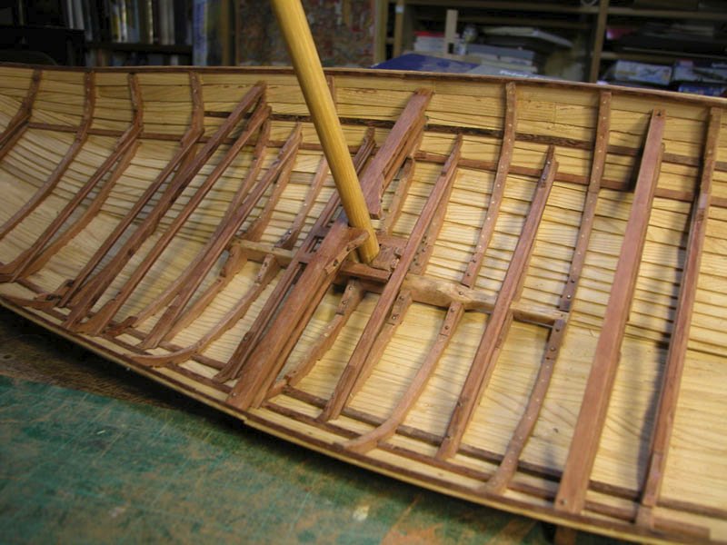
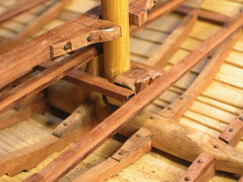
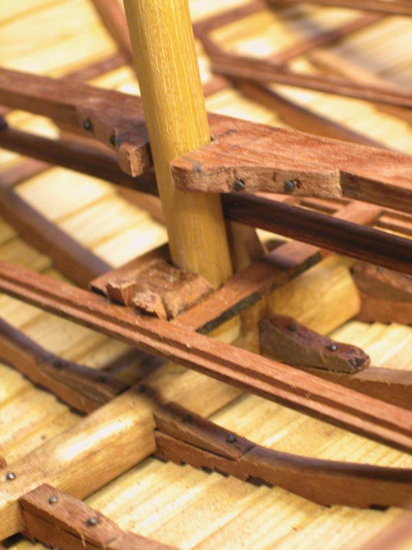
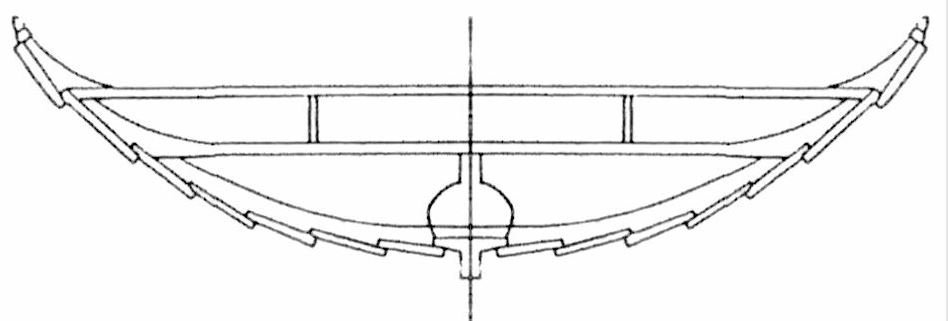
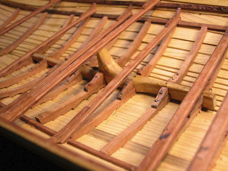
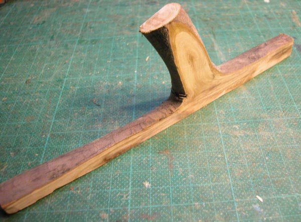
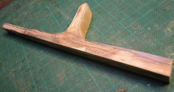
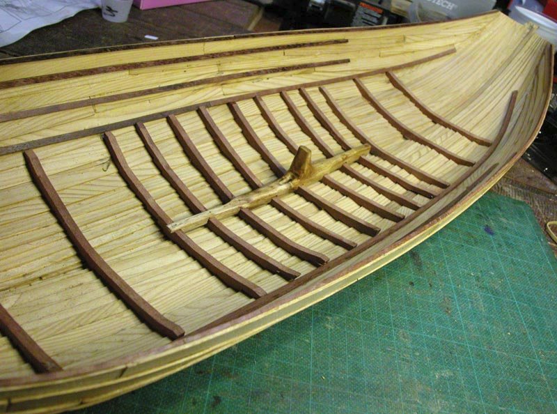
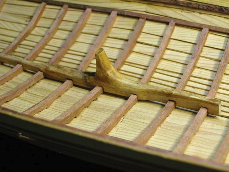
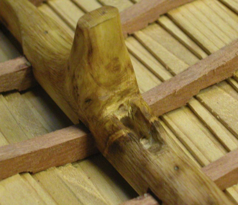
As there seems to be some discussion around nordic mast-steps, here is my take on it. The mast foot is introduced into the step slot at an angle then raised upright between the guides. The lower part of the mast abuts the vertical branch of the keelson. A rectangular timber is inserted behind the mast and wedged in place to hold and lock the mast . The mast is then lashed to the upper beam. Cheerio Dick

- 186 replies
-
- 8
-
-
-
- keelless
- reverse clinker
- (and 4 more)
-
I cant tell from available information if the keelson/mast-step was preserved in the wreck of Helga Holm. If not then the reconstruction keelson has similarities to the skuldelev wrecks: I would think that a chap of your skill would make short work of carving one from a nice piece of scandinavian wood Cheers Dick
- 186 replies
-
- 3
-
-
- keelless
- reverse clinker
- (and 4 more)
-
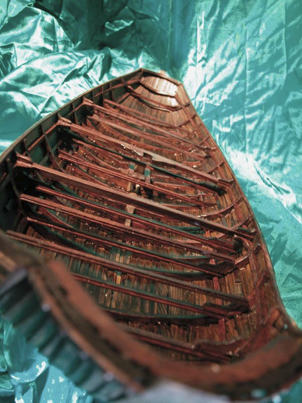
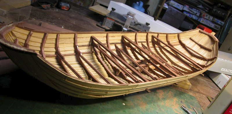
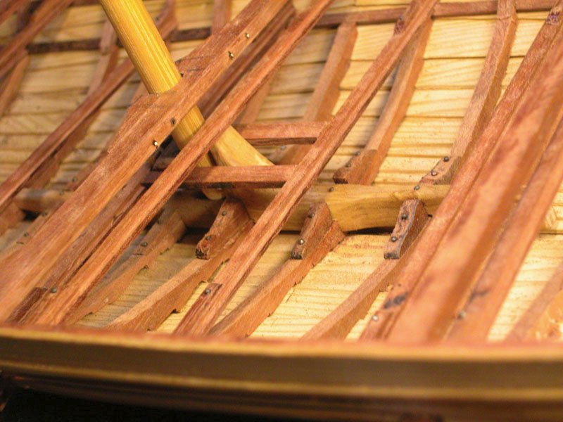
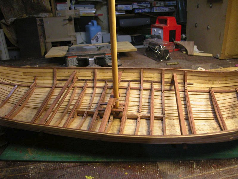
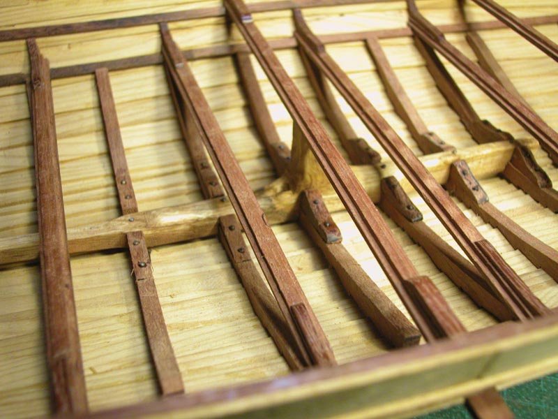
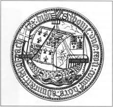
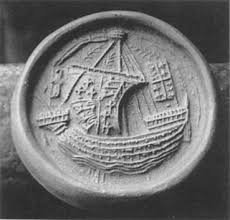
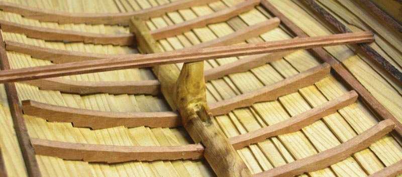
Yes, indeed, Steven. Following along the nordic theme. Here is the central part of the varmint framed loosely based on Skuldelev 1. The framing is providing some much needed stiffening to the hull but I suspect that the hull would have "worked' a fair bit in a heavy sea. Note that three of the beams are through beams. These through beams are seen on many of the hulc seals. Cheers Dick

- 186 replies
-
- 9
-
-
- keelless
- reverse clinker
- (and 4 more)
-
I don't know. There are no fruit trees in the park but a range of native australian trees. The canine collector did not tell me from which tree it derived. Dick and Maggie🐕
- 186 replies
-
- 2
-
-
- keelless
- reverse clinker
- (and 4 more)
-
Well, dang it! I just wrestled it off the dog. Plenty of fallen wood around the place. Just needed a tad of whittlin'. Dick
- 186 replies
-
- 1
-
-
- keelless
- reverse clinker
- (and 4 more)
-
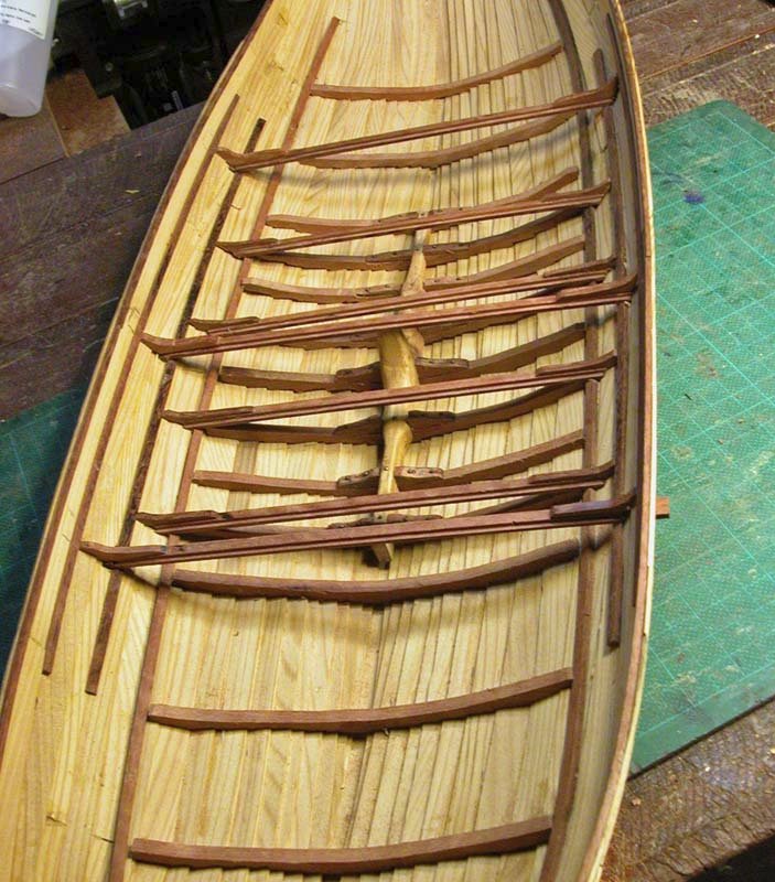
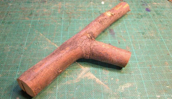
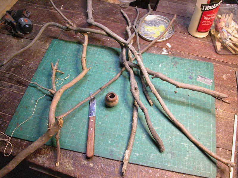
I haven't neglected the hulc, folks. Here are the steps in the making of the Skuldelev-like mast-step/keelson using a piece of local hardwood from the park. The pattern in the wood is easy on the eyes. Cheers Dick
- 186 replies
-
- 12
-
-
- keelless
- reverse clinker
- (and 4 more)
-
Didn't know you were a sandgroper ( a fond term for native-born west australians). Yes Chuck, I will make stocks as well as 4 more anchors which will be tied down on the stocks on the foredeck, ready for use. Dick
-
I think you are right. We call them "honky nuts" here. I made a cooking pot out of it. It is definitely the hardest wood I have ever worked. Dick
-
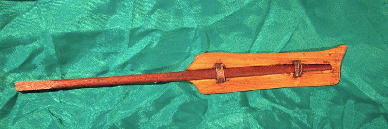
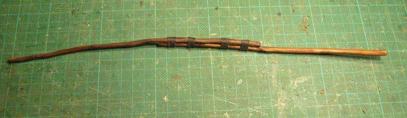
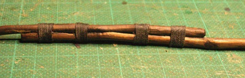
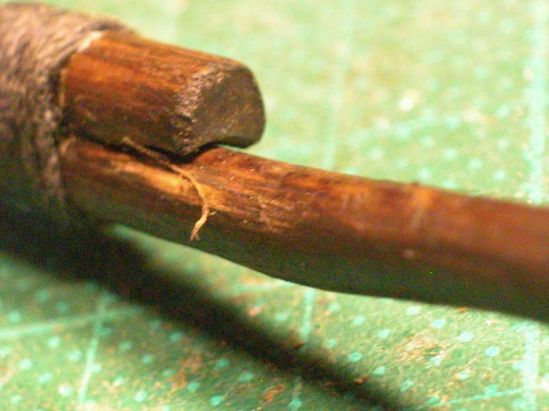
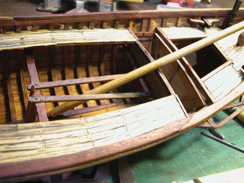
Thanks John , Steven and Schrader. Most kind. I have made the lateen yard using timber found in the local park. I was inspired by photographs of dhows which show that yards were not perfect machine turned bits of wood but somewhat rough and irregular. I suspect this was the case for this boat. cheerio Dick

- 116 replies
-
- 11
-
-
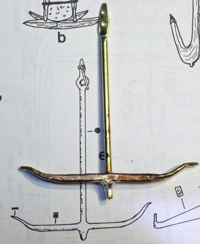
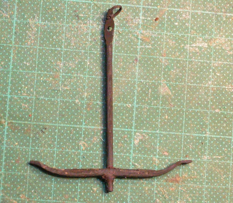
Here is the first anchor. Based on the anchor found in the 7th century YassiAda wreck and after blackening Cheers Dick
- 116 replies
-
- 12
-
-
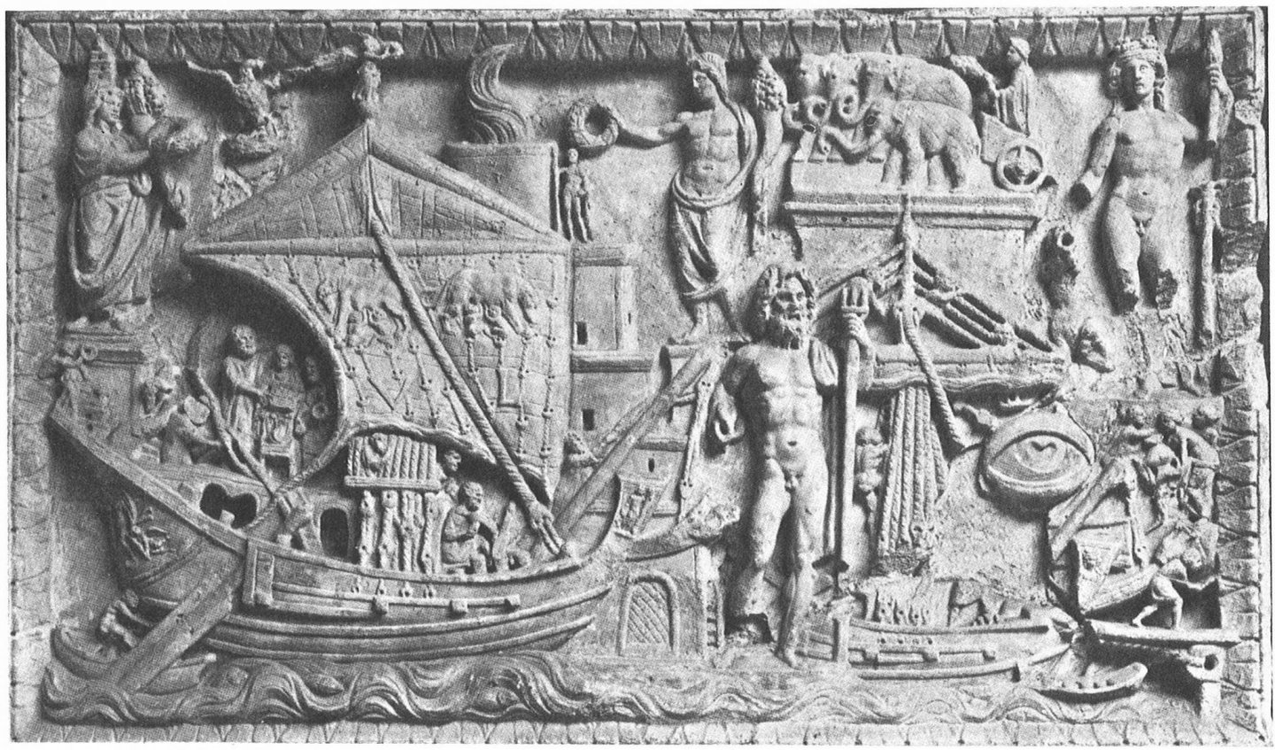
As justification for this , a bas relief from Portus Augusti in Ostia second century CE. Which indicates sheaveless pulleys on the forestay and hearts on the shrouds. Note the scuppers beneath each shroud with a rope suggesting that the shroud was looped through the scupper. I have included this on Yenikapi 12 model.
-
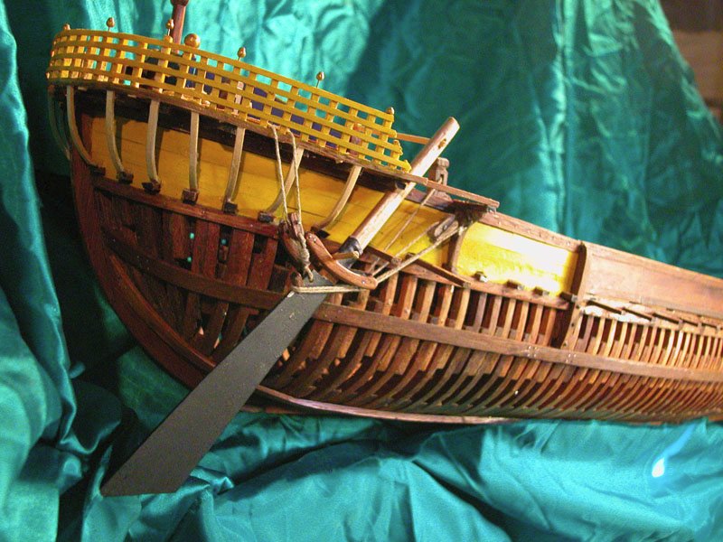
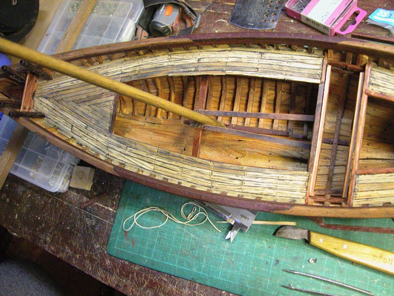
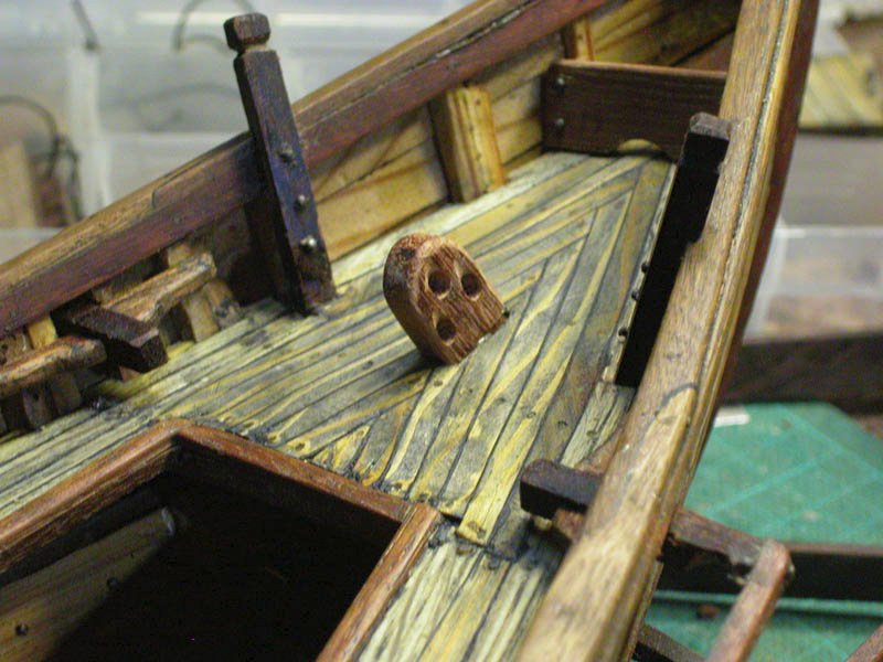
The mast did not seem to have sufficient lateral support in the absence of mast partners. So I saw a solution to this as used in certain arab dhows and have incorporated it. It also simplifies to process of stepping and unstepping the mast. here is the lower halyard block. I have decided to avoid sheaved pulleys. Dick
- 116 replies
-
- 11
-
-
Thanks, Kriswood. Nothing helps, it's just a headache that wont go away. What we call this beast is perhaps less important than seeing if this keelless banana boat is at all feasible as a practical sea-boat. There is certainly no physical convincing evidence for them in the archaeological record (see early posts for all the craziness). Using reverse clinker certainly can produce a hull but would it sail as well as an old shoe? I don't have the computer skills to put the hull into a nautical design programme, but maybe someone out there in MSW Land could do this. Cheers Dick
- 186 replies
-
- 3
-
-
- keelless
- reverse clinker
- (and 4 more)
-
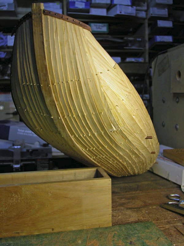
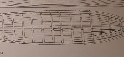
I have here a model of a hulc, boys and girls. An ordinary mediaeval transport. I now wish to plot the internal profile of the specimen. Can you get the camera on it? Observe.. I now clamp the ship to the uprights of the experimental apparatus and support its inferior surface. Why do I do this? Because the hull is weak and cannot resist torsional or laterally directed force. What allows me to draw this profile, boys and girls? It is physics! The tip of the probe exerts a force equal to a glass and a half of full cream dairy milk AND the support under the hull exerts an equal and opposite force. So, Mr Newton is happy! (my apologies to those who have never heard of the late great Julius Sumner-Miller. It's your loss) Cheers Professor Woodrat

- 186 replies
-
- 3
-
-
-
- keelless
- reverse clinker
- (and 4 more)
-
Thanks, Andrew. I fitted the bearing wheels because there was too much friction without them which led to jumping and catching of the slide. Works well now. Dick
- 186 replies
-
- 2
-
-
- keelless
- reverse clinker
- (and 4 more)
-
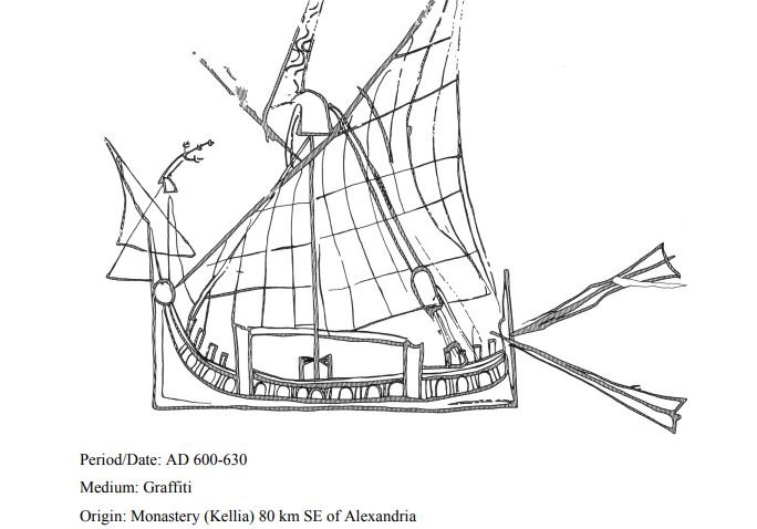
Thanks John and Steven. Louie da Fly complimenting the boat on filthiness is praise indeed. "Straight from rubbish tip to you..." The main problem now is where to place the lower halyard block. The only place I can see that it could go is on the after deck behind the steersman. To back this up I have this 9th century turkish illustration showing the halyard going toward this position. It also shows the "hockey stick" well. And if I'm not mistaken, it also shows a triangular wing on the starboard quarter. And this 7th century graffito shows even more detail" It also backs my interpretation of the hockey stick calcet. Cheerio Dick

-
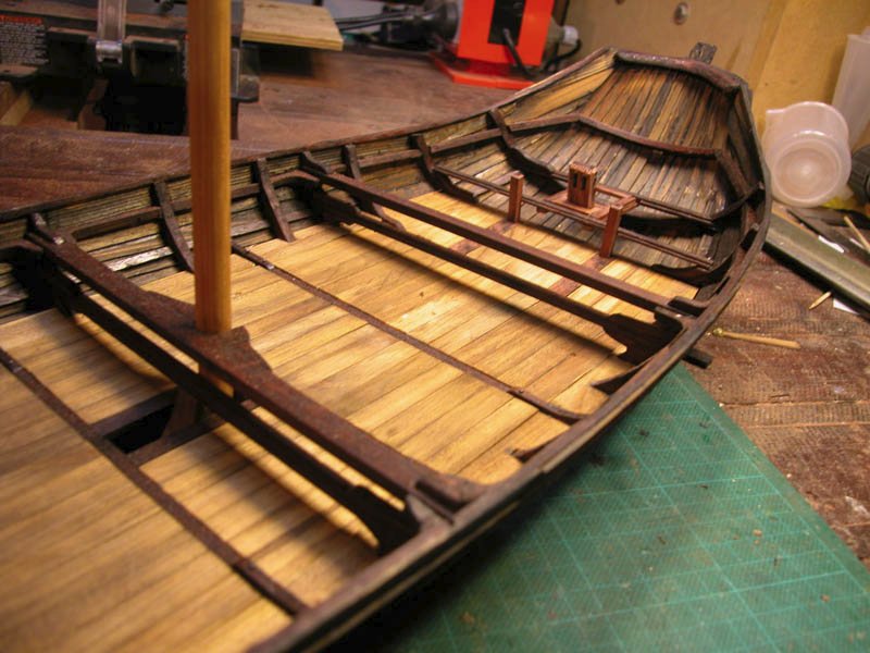
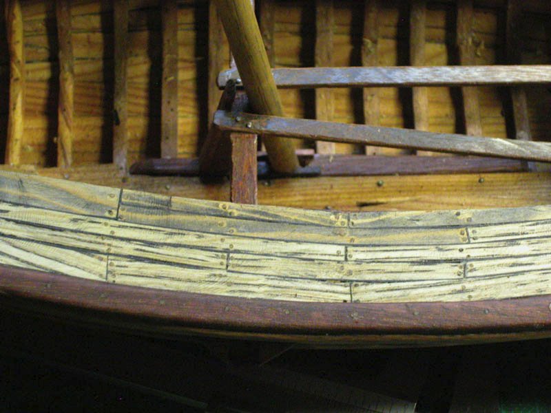
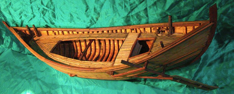
The decking is in place and I have filthied it up a treat. I think it looks like a working boat now. Little to do now but rig it. Cheerio Dick
-
The first picture is a flat cross section symmetrical rudder on the ancient mediterranean pattern and the second is a foil cross-section assymmetrical rudder of the 13th century ( on my round ship) Dick