lambsbk
-
Posts
910 -
Joined
-
Last visited
Content Type
Profiles
Forums
Gallery
Events
Everything posted by lambsbk
-
When the clamp is released secure the optic cable so it does not crack or break off the bulwark since the area of exit from the bulwark is very fragile. You can secure the cable along its length with a couple of well placed globs of glue. When you have all the completed cables ready run them through the previously drilled exit hole in the keel and secure them gently (no harsh bending) under the build out of the way until you are ready to pull them through a mount when the build is complete.
-
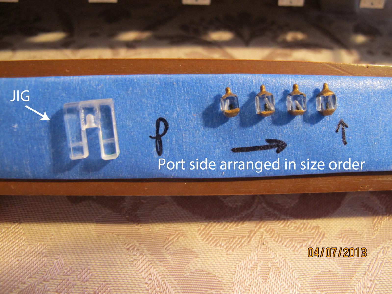
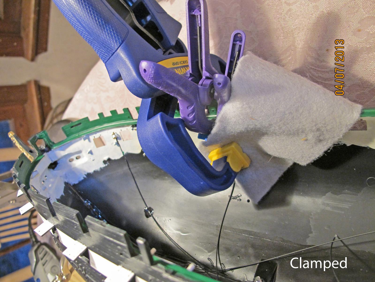
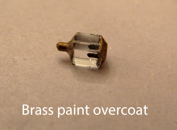
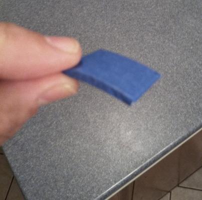
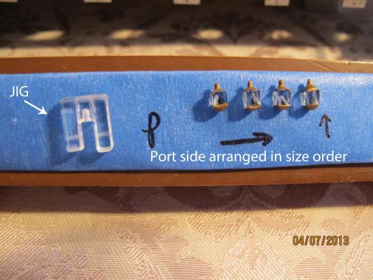
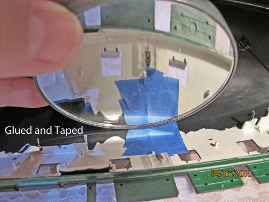
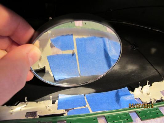
There will be a little variability in the size of the completed lanterns. Size them in order from smallest to largest and place them fore to aft in this order. This will prevent obvious size variance observation to the casual observer. Next make item 3 out of a piece of paint stirring stick and painters tape per the pic below. It's a little blurry but you get the idea. To mount the lantern - with the lantern fit to the jig and ready to go - fill the cut with plastic cement - gel type - and fit the optic cable into the cut allowing excess glue to over flow the cut. Push the jig flush to the top and place a piece of blue painters tape over the optic cable and the cut groove so it widely covers the area. I used the covered paint stick (item 3) to compress the optic cable into the cut groove by placing the curved portion over the center of the optic and clamp it relatively tightly to the hull with the grip clamp (item 9). The press of the paint stirring stick will even out the glue and the painters tape does not stick leaving a renewed smooth surface to the bulwark when dry. After repainting the area it looks like this:


-
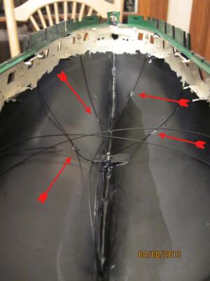
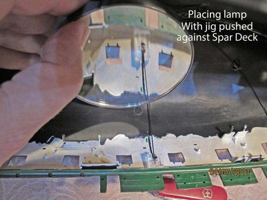
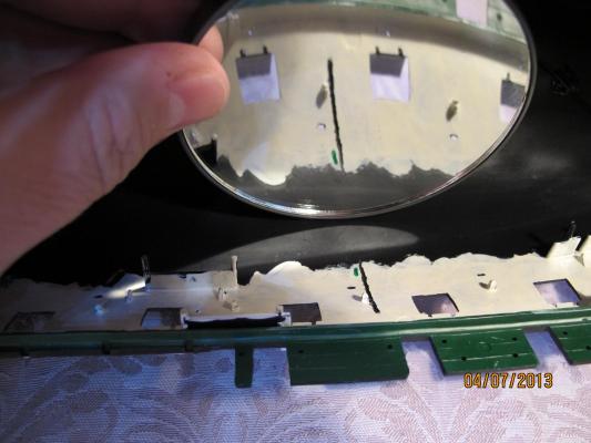
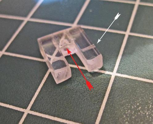
Well, if you have not thrown in the towel yet chances are you are ready to tackle the next project - mounting the lanterns. This will take some individual skills and varies depending on the build. For instance a wooden build can probably run through the bulwark depending on its thickness but may require modification. For the plastic enthusiast several members of this forum have thickened their bulwark to better reflect the actual bulwark of the ship. For them it is simply a matter of incorporating the fiber optic into the styrene with a hole as an access for the optic. I did not thicken the bulwark on my build but cut the plastic from inside the hull to incorporate the optic cable. This took care but I must say was not as hard or as dangerous as I thought it would be. You will need a lantern jig next to keep the lantern height even from the top of floor of the spar deck above. I made mine from scrap plastic acrylic stock...there is plenty from the lantern production. I used a Dremel with a small cone rotary file attachment to hollow out a receptacle for the lantern top and a drill to hollow out the center for the lantern cap (red arrow). The sides were then glued on with CA. I had to file a little off the inside so the lantern could move freely within the jig. I then scored the jig at the optic entrance to mark gauge it's height on the bulwark prior to making the cut (white arrow). I rounded the top of the jig to allow easy removal from the lantern after the glue is dry. To describe: it looks like an upside down "U" when viewed from the side. Just dry fit the jig to the bulwark and use the scored jig to transfer a stop line to the bulwark. Remove the jig before starting your cut. This shows the jig and lantern assembly (the lantern here is simplified to show position). The cut into the bulwark was done by first taping off a line to follow. I used a Dremel and 1/32" engraving bit. The tape protects the work from 'bit jumping' and is a good work guide. The bit is touched over the plastic like using a pencil to sketch. Dremels work for you because of the speed. Minimal pressure is needed for the cut. Keeping the Dremel at a 45 degree angle will help prevent cutting too deeply. After a couple of passes check the fit of the optic cable. The cable should be flush to the bulwark above the gun deck and can exit the hull in a tapered fashion below it. Make your mind up about how far up to bring the cut depending on your mounting preference - remember the cut will end at the height of the optic cable's entrance INTO the lantern from the bottom. Once the cut is completed for both length and depth clean up the extra plastic debris completely. Re-test for fit and if you are satisfied you are ready for the next step A WORD OF CAUTION: I planned on evenly spacing my lanterns but the first cut was one gun port to far back. 'Measure twice cut once.'
-
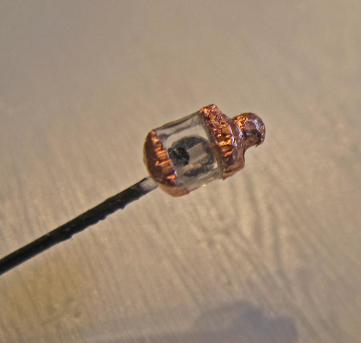
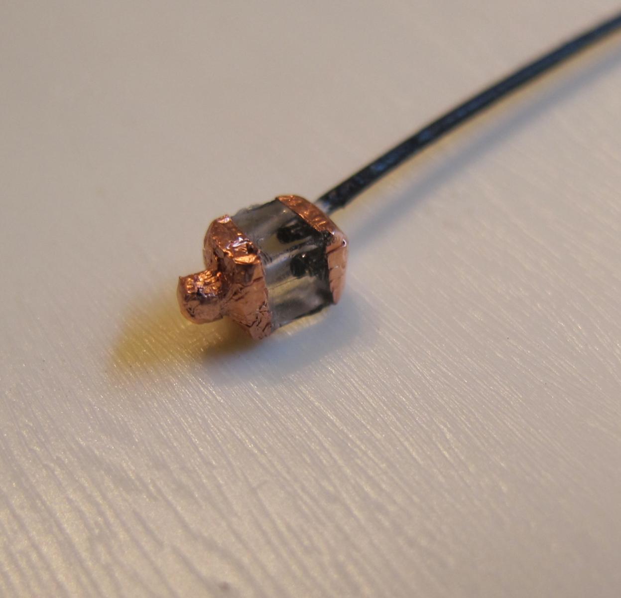
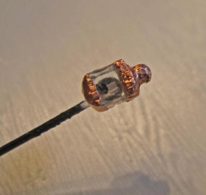
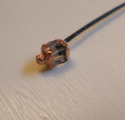
Just for the fun of it I tried adding some copper foil a friend gave me to the lantern I just made. OK - it really does not look that good but here is an advantage - no extra light transmission through the foil. It was a PITB getting the foil on this lamp and I believe would require the patience of Job to do more than a few but it made me think that thicker metal shaped correctly could speed up the lantern process. If anyone has a press and can shape the caps and bottoms of the lanterns they would look better, be produced faster (since no lathing need be involved on the plastic stock), and would block top and bottom light transmission. The holes then would be the only production item that would take time and that too could possibly be automated. Oh...and a side note - I did use CA to attach this reflector and it IS holding much better to the acrylic lantern than Hypocement. It also dried perfectly clear.
-
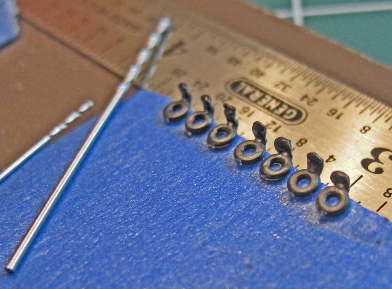
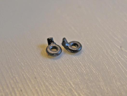
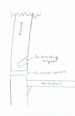
The ring bolts for the breeching of course are not ring bolts but eyebolts with the stems at 90 degrees bend. They are then inserted in the breeching hole above and the bend simulates gravity pulling the bolt down as seen in the breeching pics - again on the previous page. The eyebolts are bent by placing them in a row on tape then clamping them gently in a vise with only the stems showing. The vise protects the bolt eye. I used a heat gun to heat the exposed stems and a metal ruler to bend them all over 90 degrees when the had started to soften. It's a little tricky but most of them turn out ok. When complete I leave them on the tape until needed - a little filing to return the stem to the correct diameter and they are ready to lash to the breeching line followed by mounting on the bulwark. After bending... After reshaping a little... When complete the 90 degree bend allows them to 'hook' into the 45 degree hole and the glue does the rest.

- 601 replies
-
- 1
-

-
- constitution
- revell
- (and 1 more)
-
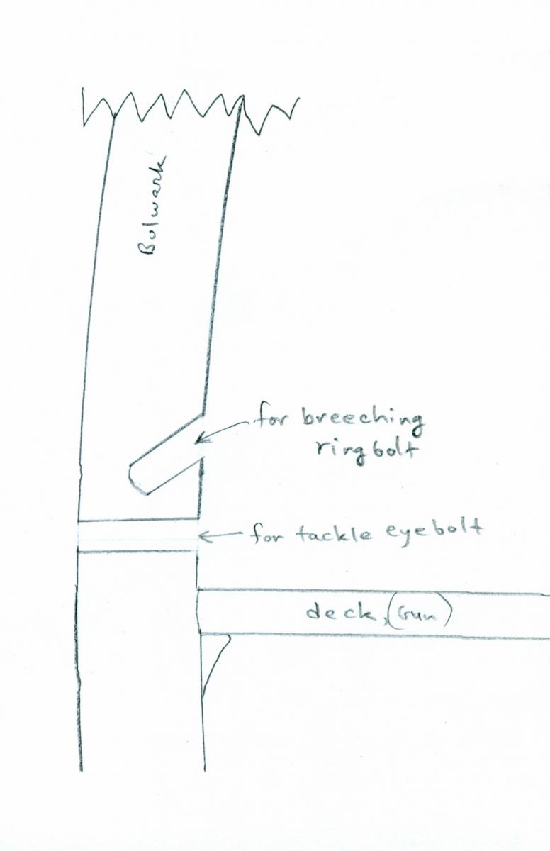
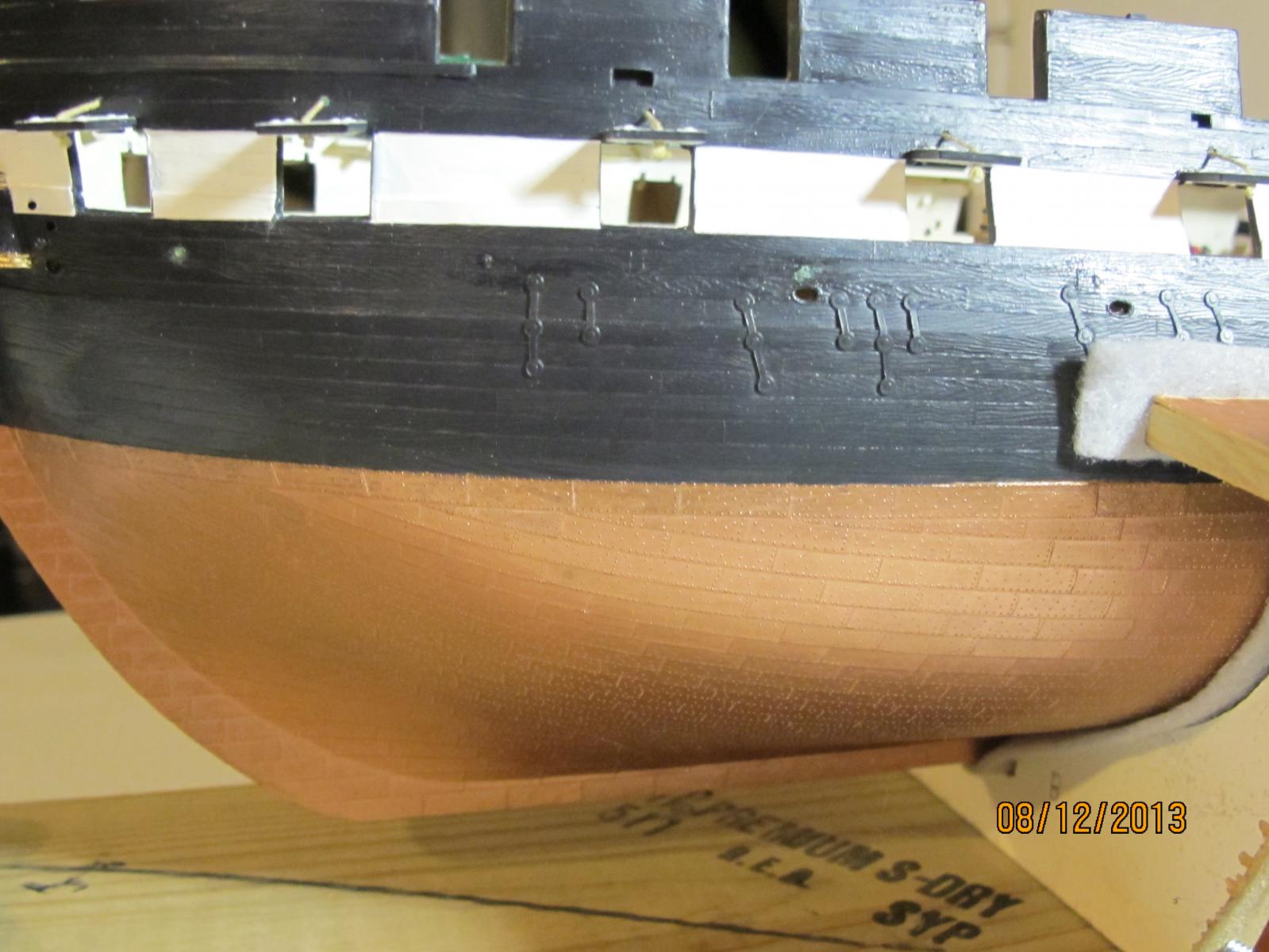
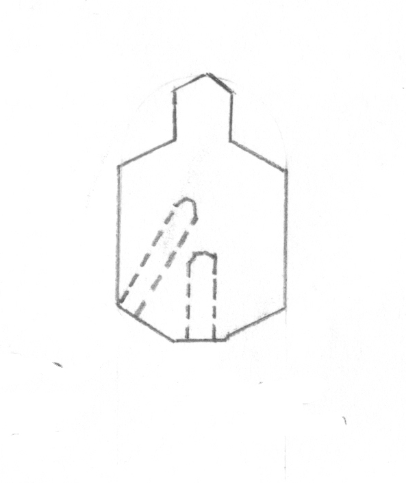
I am adding some detail about the eyebolts and their modifications. You can see the relative positions of the bolts in the pics of the canon breeching on the previous page. The drawing below shows the drilled holes and their relation as viewed from the side. Note: they are not on top of each other. The breeching hole is adjacent to the gun port and the tackle hole is between the ports.
-
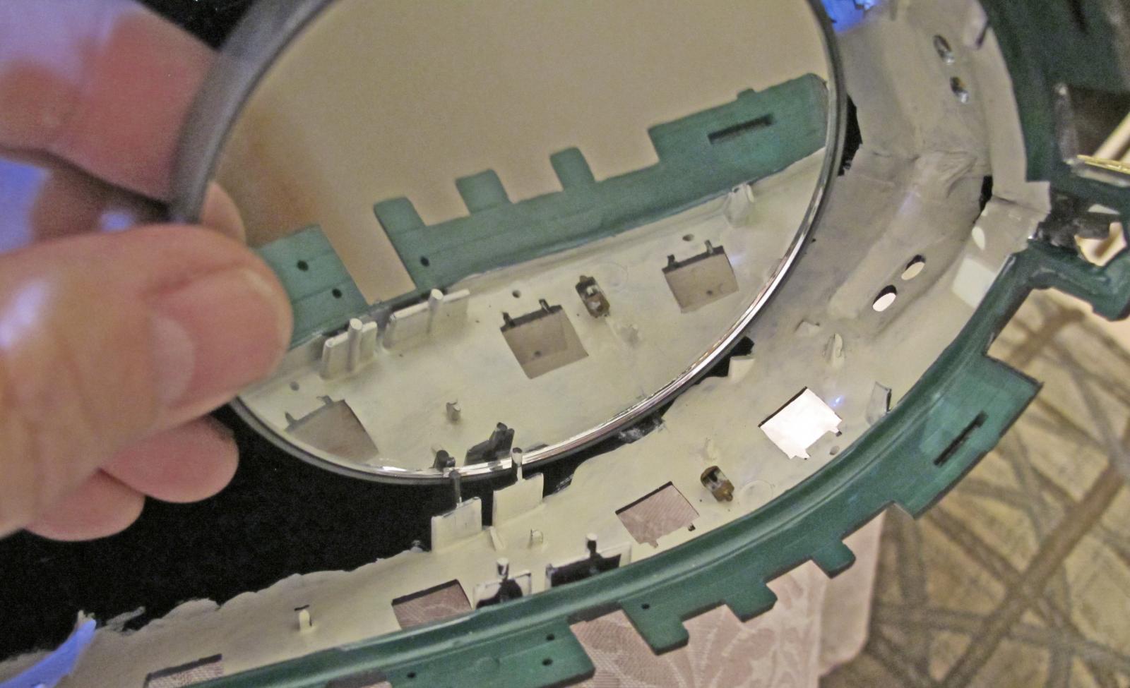
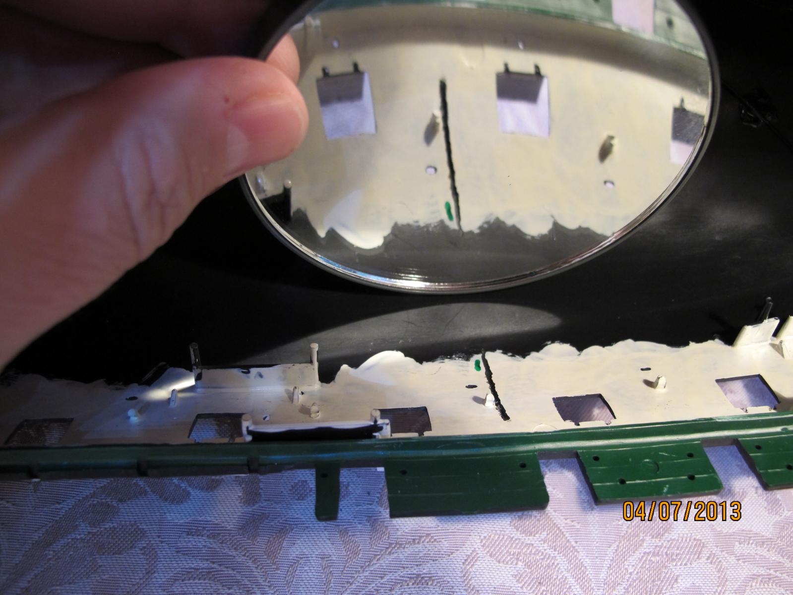
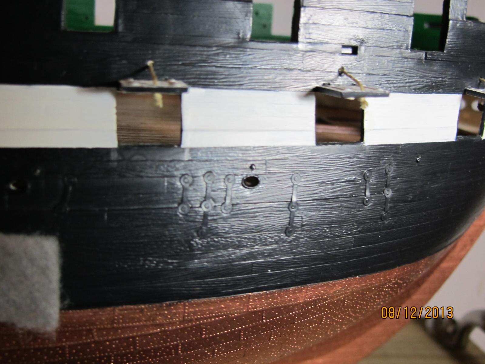
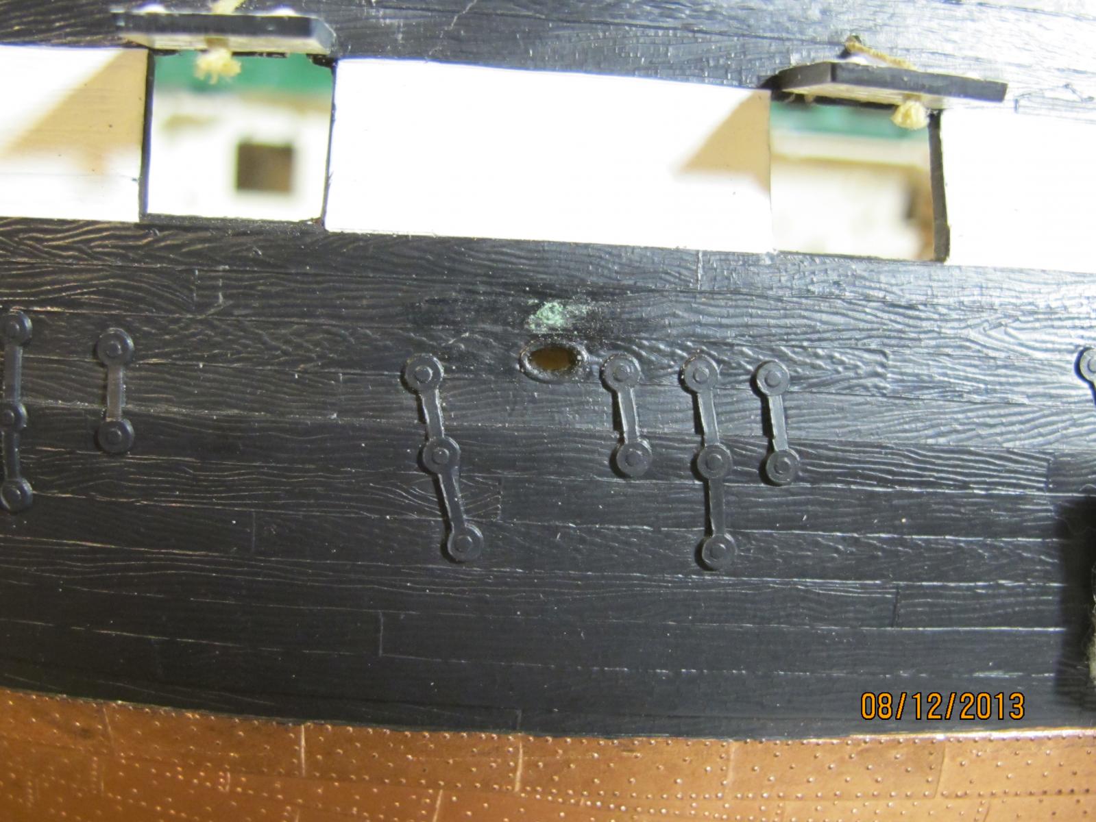
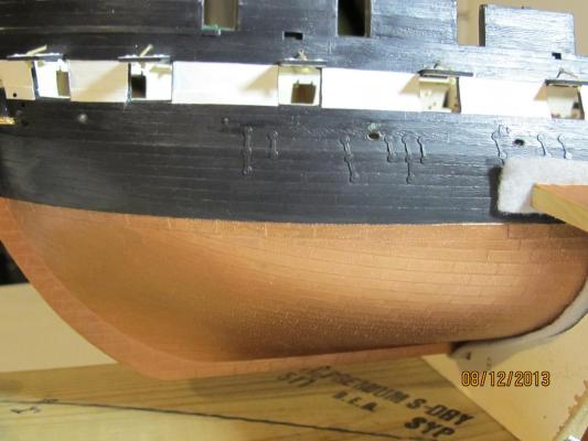
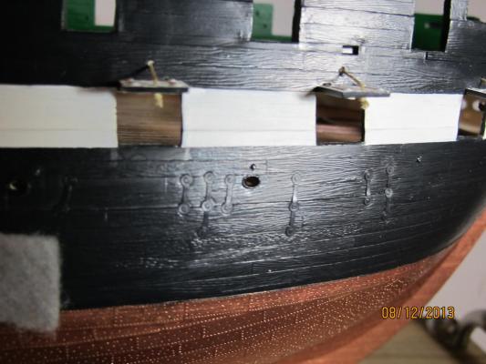
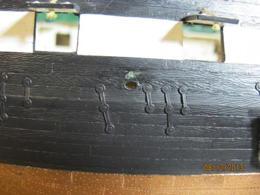
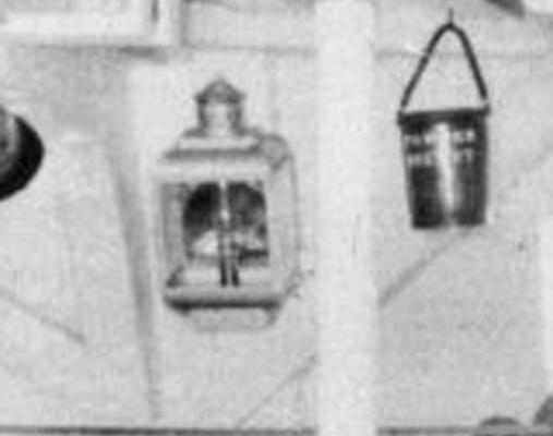
Rick: Sorry to get these up so late for you. It shows the breeching bolts from the outside. The putty is obvious. I will probably paint it later to match the hull. You can see some of the bolts that have no putty as well. Up close it is easy to see but not so much from a distance at this scale. This one has a light source reflecting to see the detail easier. And really up close...
- 601 replies
-
- 1
-
-
- constitution
- revell
- (and 1 more)
-
Sorry Verne: the reference for the decks is on page 1. The transom detail was page 2. Sorry for the bad reference. I hope you found the info anyway.
-
Nice idea.
-
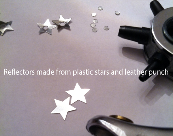
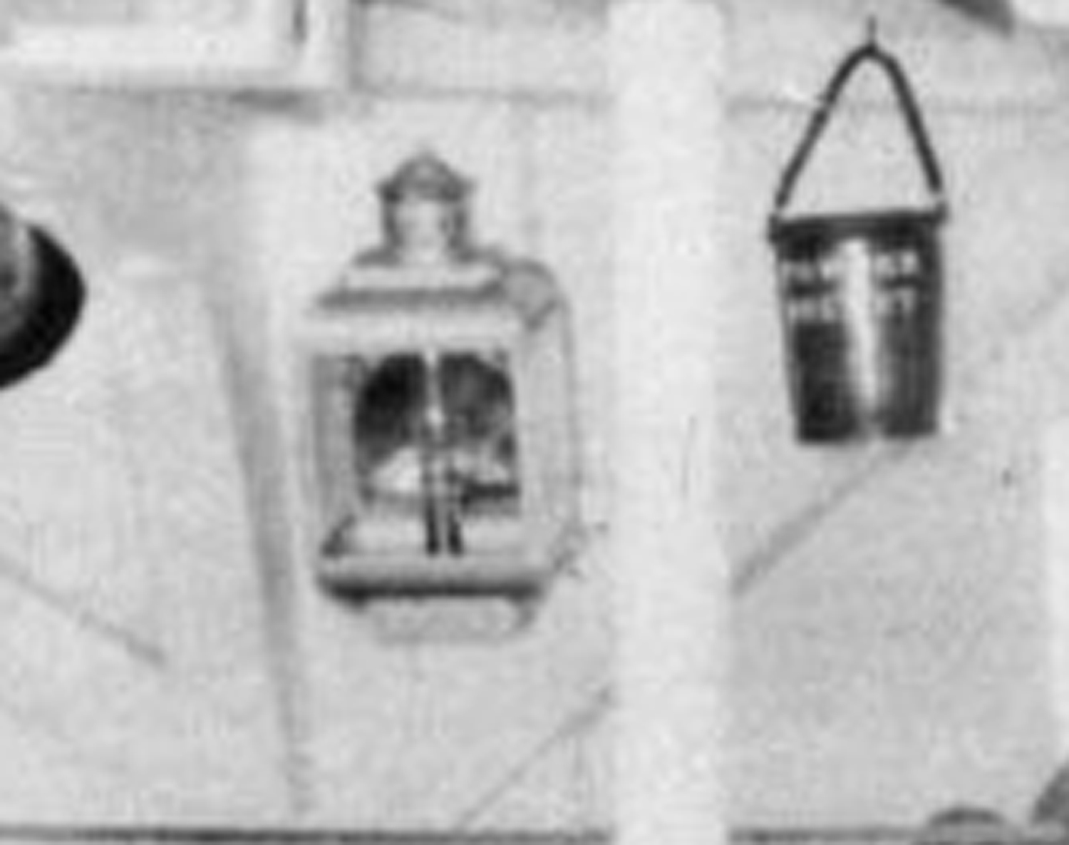
The reflector seen in the black and white photo is the next item to make. This is not very hard. Use the leather punch (item 10) and some of the cheap plastic craft Mylar items . I found mine in the garage from a craft project of the kids. They should be relatively firm but THIN. Punch out a reflector from the smallest setting on the punch. They tend to get stuck in the punch (since we want what would normally be waste for this tool.) A long tooth pick or straightened paper clip will free your reflector. The punch process creates a natural concave image on one side. Locate it. This is the inside of the reflector. Glue it on with Hypocement or CA (although I have not tested the CA for clarity it will have a better bond.) Center it carefully behind the optic to match the vintage B & W photo seen previously. Let it dry completely. After the reflector is attached we are ready to prepare the bulwark.

-
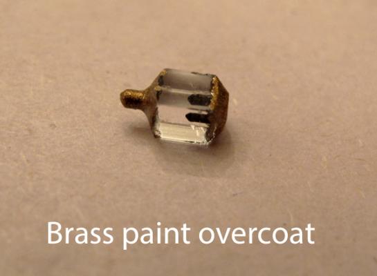
Now paint the top and bottom of the lantern the metallic color of your choosing. I painted mine Testors Brass. Cover the flat black base coat but avoid the lens of the lantern carefully.
-
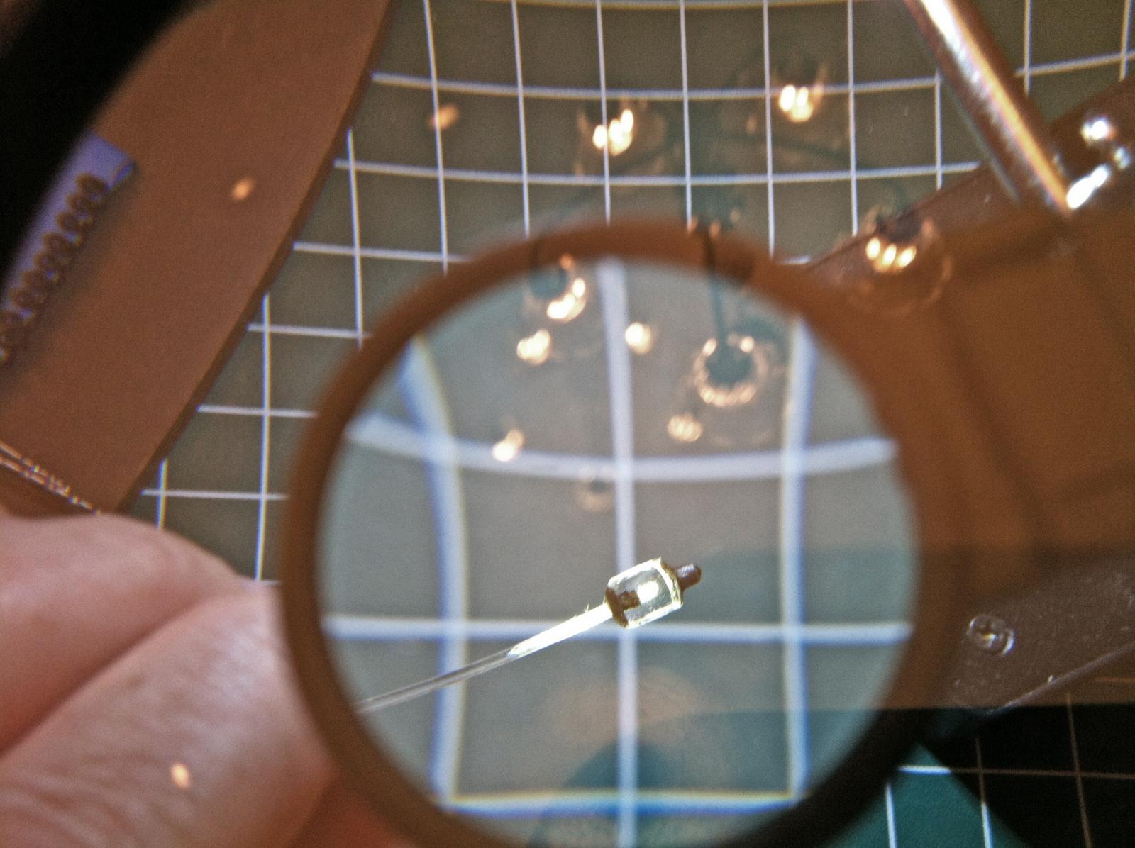
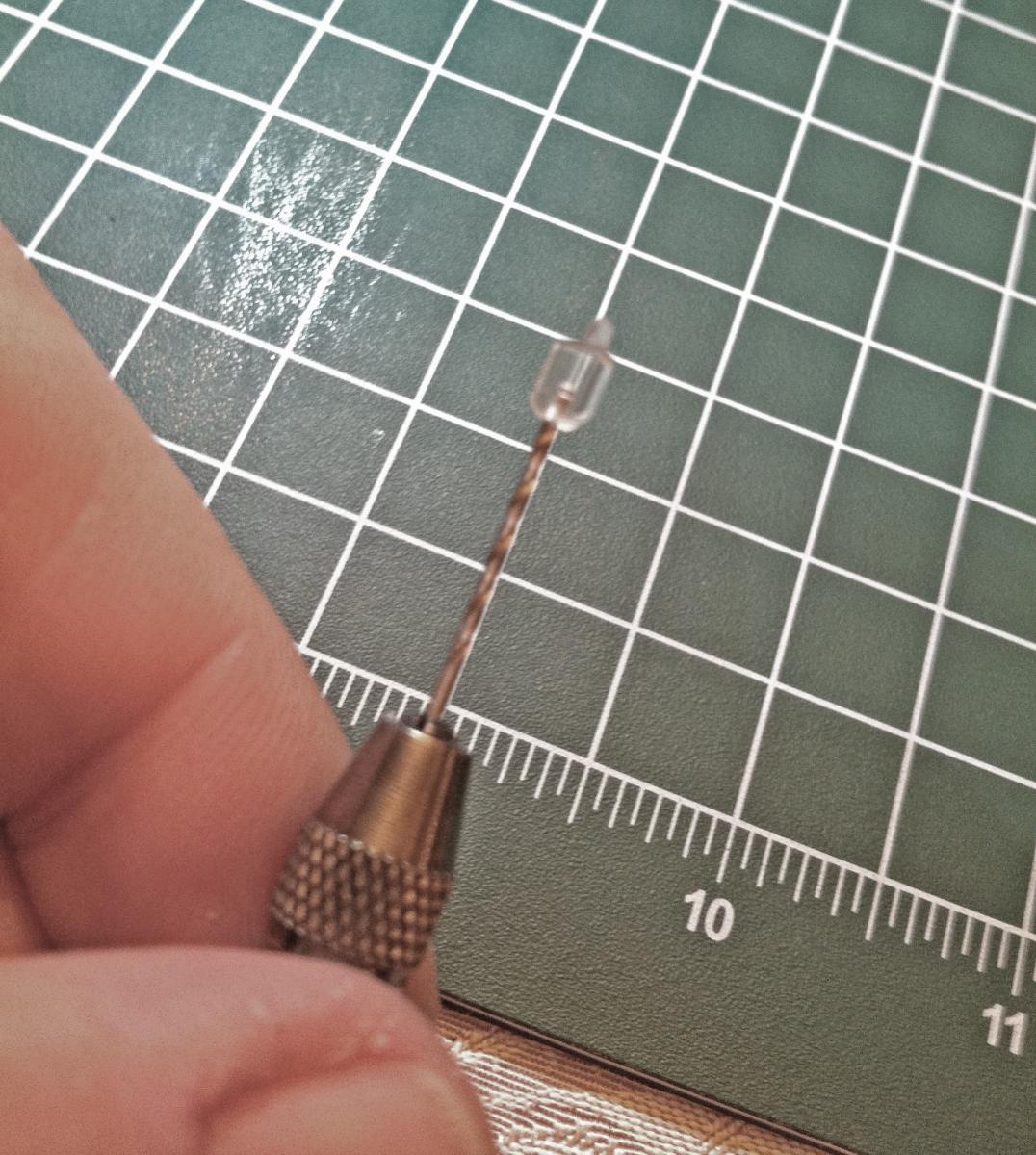
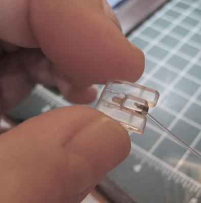
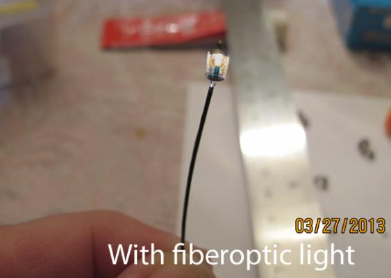
If you drilled the holes correctly the fiber optic should fit snuggly into the lamp. It is this cable that will mostly hold the lantern to the bulwark after gluing so it should have a good fit. The natural plastic curve of the optic cable should follow the curve of the hull. This is the lantern with a little light put to it. Once you are happy with the fit use your flat black paint and paint the optic cable as far as you can without affecting the cable that will be in the lantern. This helps prevent side firing light from showing up. Paint the cable for the entire transit of the ship, again to prevent bleed through and side firing light,

-
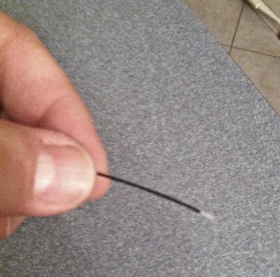
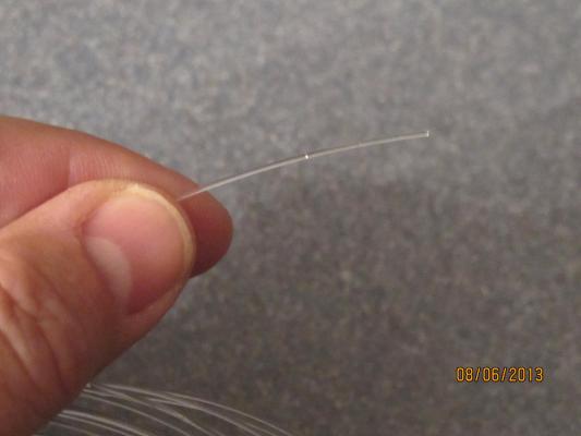
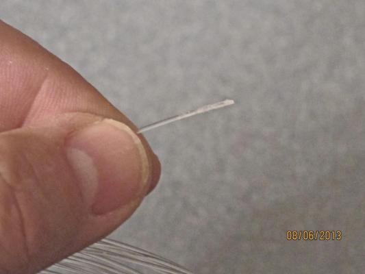
Next prepare some of the fiber optic cable. You will need a fair length of it to run to outside of the ship. Most of mine were at least 24" long. Taper the lantern end with a bit of emory board to 'rough' up the end. This will allow better light transmission at the tip. Before After
-
The next steps show how to fit the fiber optic to the lantern. You will need to drill a hole the same size as your fiber optic cable parallel and tandem to the oil container hole as shown below. It needs to rise up and behind the oil container. This will transition the cable into the lantern from the bulwark or bulkhead, depending where you are putting it. Try to make the cable hole as straight up. When I misguided one of mine I had a tough time straightening the lamp on the bulwark even with a jig. The cable is very unforgiving concerning sharp bending. Side View Rear View You can see I am out of practice here. My hole is not quite perpendicular to the base as viewed from the rear. If I was going to mount this lantern on the ship it would give me some alignment problems.


-
Verne: It really is a composite of techniques. Andy (andymech) really is the trailblazer in this area of the build. Check out his completed build at http://modelshipworld.com/index.php?/topic/129-uss-constitution-by-andymech-revell-plastic-196/. In addition, I gave a detailed idea of how I painted the decks on page 2 of this build as well. I hope that helps.
-
I think Revell did not want the deck glued for 2 reasons: 1)If you glue the gun deck it is very hard to tell how far to compress the hull around the gun deck to match the fit for the Spar deck and 2) (although I have not run into this yet) Andy says the masts need a little bit of float to get them aligned. Since the Spar deck does not move the gun deck is the giver here. Personally I plan on shaping the gun deck mast receiving supports to get the placement needed. The rigging will also alow the masts to be adjusted (eventually). PS: My gun deck is joined at the seams but does still float laterally, at least in the forward section. I compressed the hull because I did not want my gun placement, breeching, and tackle to move when the spar deck is finally attached.
- 79 replies
-
- 1
-
-
- constitution
- revell
- (and 1 more)
-
Here here. Well said.
-
I concur. It was one of the problems I wrestled with on the gun deck as well. As a result I went through a bit of a tedious exercise in trying to reestablish it. I am not sure how successful that venture was: I used a radius of arc method and worked it to 50". It was enough to get the camber back. I epoxied several pieces of cambered wood behind the gun deck but I wish I had scored the plastic before attaching them...epoxy does not hold on to the plastic that well and CA was used to repair the lost holds. A side benefit was the alignment of the deck pieces to get a close approximation for gluing. Just a note: the deck pieces are NOT the same thickness - at least on the gun deck - a careful consideration if you use tabs to join them.
- 79 replies
-
- 1
-
-
- constitution
- revell
- (and 1 more)
-
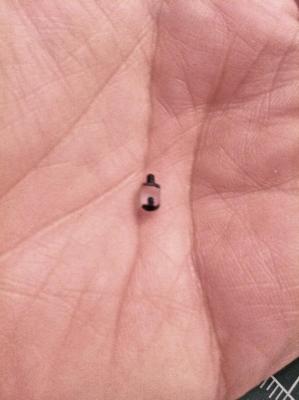
Next get the micro-brush (item 6) and some flat black paint. Paint the top, bottom, and hole for the oil container flat black. This prevents light bleed through from these areas. Be careful to avoid the lantern lens.
-
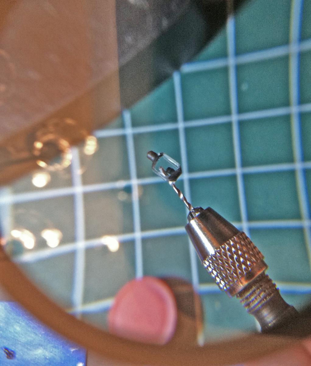
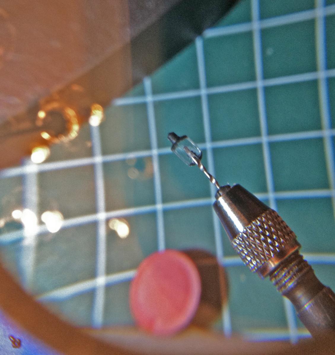
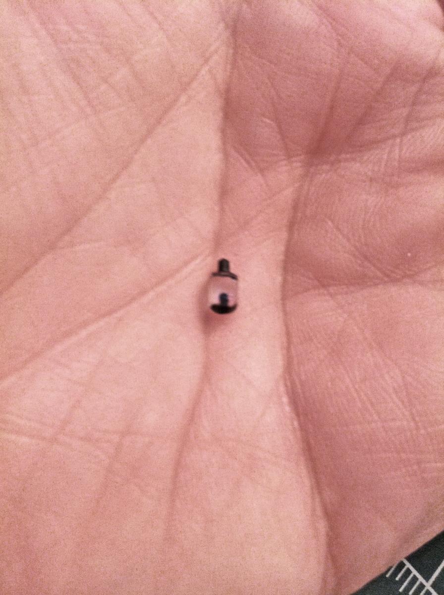
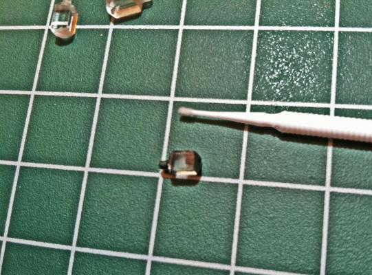
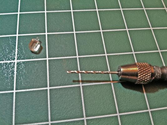
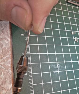
Ok. On to the next step. This is what we are trying to get to: To continue on finalizing the lanterns a hole must be drilled in the center bottom to a depth that approximates the oil container in the above photo. The drill bit or hole size works out to anywhere between 0.020-0.025 inch's. Most small hobby micro-drill sets have these sizes. Just do this using the hand drill to get better control. Turn the piece 90 degrees every few twists to ensure you are boring perpendicular to the bottom of the lantern. When complete it looks something like this. (I made the hole larger than the above description for photos. Also some redish background light appears in these photos as artifact).

-
Hello Tim1786. Several members have used wood to make their decks. I personally do not know how those work out. If you do a general search in the main MSW home site for words such as 'constitution' and 'plastic' or 'Revell' you should see most of the builds for this ship. I expect you will find some of the deck methods you are looking for. Good luck.
-
Henry: I am still a ways from finding out. I.e. I am afraid you will know before me on this one. I hope some of the other more experienced modelers have had some luck with this problem. I started a thread last year to discuss it but not much info was exchanged.
-
From here Henry it look s superb. Fixed..? I've got some plastic Connie parts that would love to look that good ANY DAY. Nice work. Dave PS: I may have to use dullcote as well. I have had trouble with the gold testors paint showing signs of 'handling' even when there is no handling going on.
-
Henry: what gauge wire is that? I like the over all look very much. So far I have used beaders tools with a small tip. Even that was too large for the eye so I used a small diameter drill bit and first wrapped the wire circumferentially pulling it tight. After removing the bit I snipped off one end of the wire near the shank and straightened the shanks coarse. You can get really small eyes (and sore eyes) doing this. I have not quite got the curve of the hook yet. Dave