
HOLIDAY DONATION DRIVE - SUPPORT MSW - DO YOUR PART TO KEEP THIS GREAT FORUM GOING! (89 donations so far out of 49,000 members - C'mon guys!)
×


Captain Al
-
Posts
613 -
Joined
-
Last visited
Content Type
Profiles
Forums
Gallery
Events
Everything posted by Captain Al
-
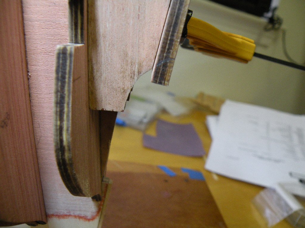
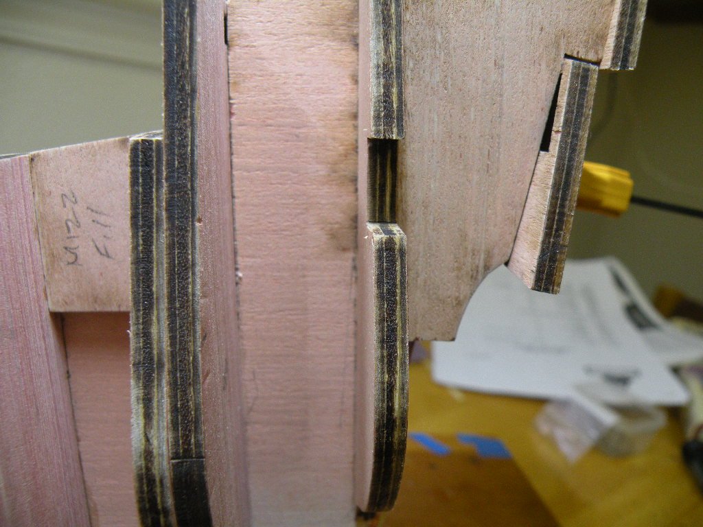
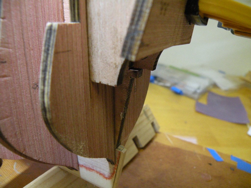
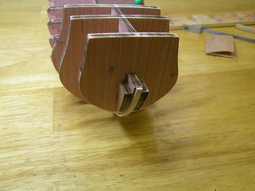
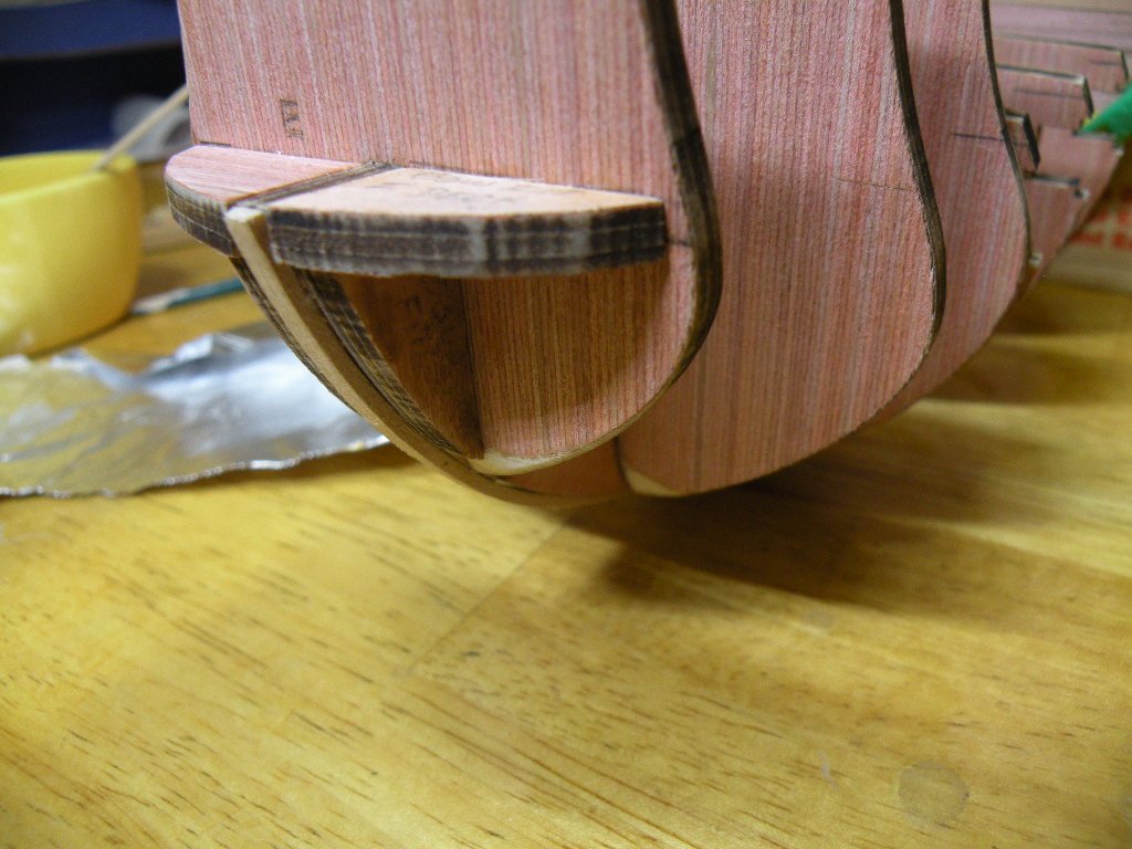
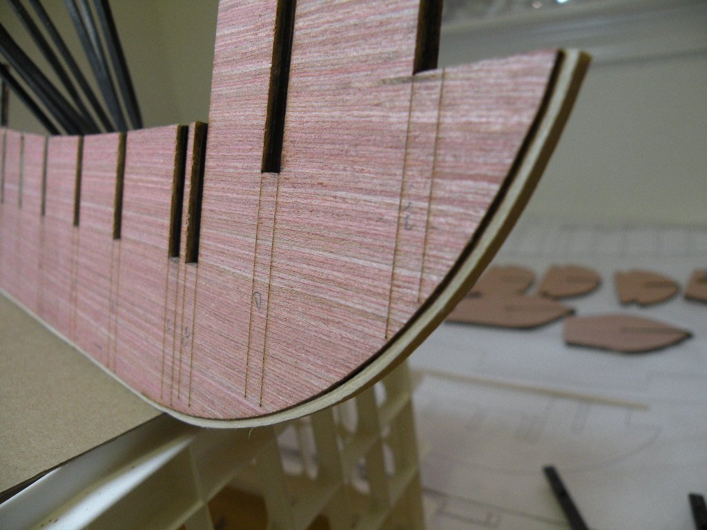
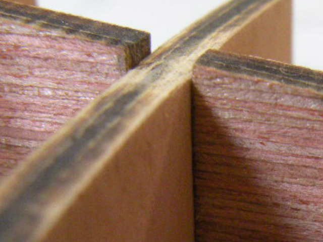
Going to try Danny's way of inserting pics into my text. Hope it works..... Part YY's bottom edge forms part of the counter which is a finely curved section that will be planked over shortly. These pix show this curve in the frames and how the part YY overhangs it and needs some radical shaping. I

-
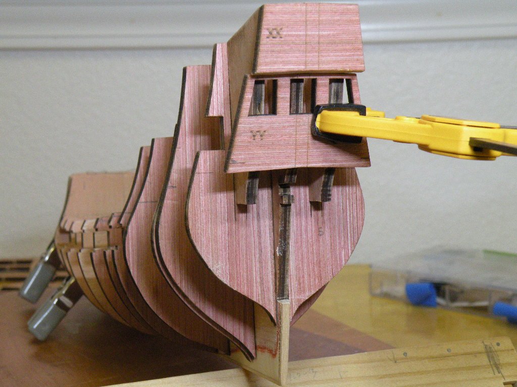
Time to move on and glue on the stern pieces XX, YY, and ZZ (shouldn't ZZ have been on Top?) The reference lines are great. Sure beats taking measurements off of plans and transferring them to the parts to draw our own refrence marks. So the east west orientation of all 3 parts is a given. Chuck notes that the orientation or reference lines of part ZZ (if you still haven't gotten it I guess you weren't into '70s R&R) are only 1/8th apart. This is because by this time we've tapered the stern to 1/8th and it leaves no wiggle room. I went through a long process of test fitting the 3 parts cause the top and bottom edges are not as straight forward as the side to side placement. Starting with part XX, the top edge needs to be beveled to match the slope of the BF and the two stern frames. I think the bottom edge should also be beveled. It appeared to me that it would be alot easier to do this off the boat before gluing on. Seems like a good deal of wood will need to be removed. I did most of it by hand filing. At the end I used a disk sander to just take the slight roundness off the beveled edge. In doing this care must be taken to keep the camphored shape to the part. Swoop the piece in an arc across the disk. And like I said, very very gingerly. Or better yet, don't leave the bevel with a roundness to it in the first place. First two pics show the part in process. Last one shows it glued on after the disk sanding. Hard to tell but the line to the frames and BF is good and flush and the false deck will sit nicely.
-
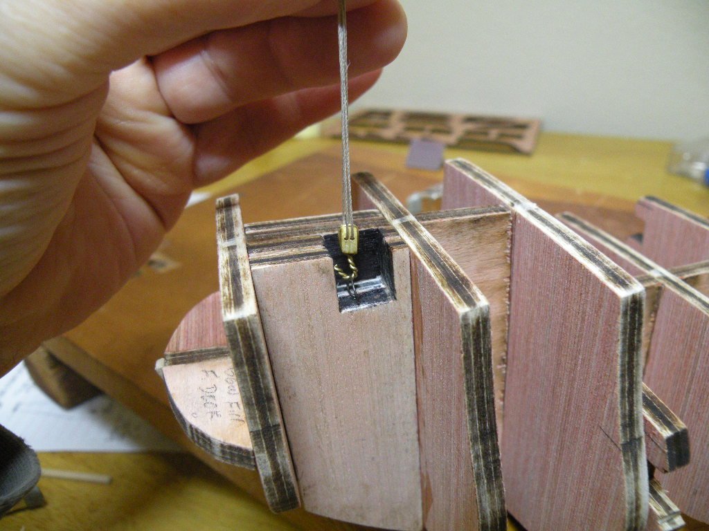
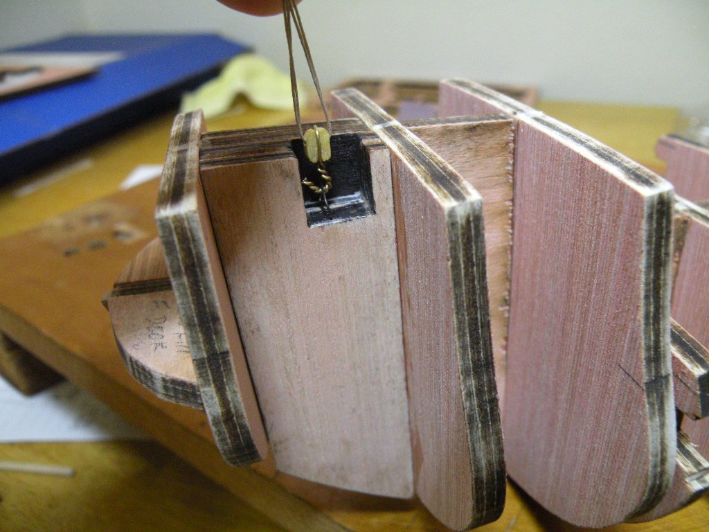
I know I'm belaboring this point, but my sense of perfection (where did that come from?) seeks an answer if there is one. So please endulge this for one more post. I know from both modeling and real sailing, that both standing and running rigging need to run smoothly through their blocks or deadeyes toward the point where the lines will be rove through a second set of blocks or deadeyes. There should be no twist in the lines. To make this happen the sheaves (or holes in deadeyes) of both sets of blocks must be parallel to each other and to the lines themselves. If they get hung with the sheaves perpendicular, the lines will twist 90 degrees. Knowing this, when hooking a block to an eyebolt (say for example on the deck), its important to know how the hook to eye connection will end up orienting the sheaves (in our modeling world, the holes through the blocks). This, is why (I assume) in the case of the eyebolt in the foremast filler, Chuck makes note to face the eyebolt forward. But, this also begs the question of what is the proper orientation of the hook attached to the block? Is there a right way and a wrong way? Should the eye of the hook be parallel to the sheaves (i.e. looking in the same direction), or is the proper way to attach a hook (or becket) to a block being to make the eye and the sheaves perpendicular? I've noted somewhere that in modeling, when the time comes for rigging, and lines are being rove through the blocks, if it should turn out that either the eyebolt or the hook is oriented incorrectly resulting in lines that are twisted, the problem can easily be fixed by making an addition quarter twist to the hook (assuming that's the way you've stropped on the hook to the block). But in real life, if the eyebolt is secured to the deck facing the wrong direction, or the hook has been stropped to the block incorrectly, its alot more work to fix it. So I'm guessing that for the sake of communication and everyone knowing what someone else will be doing, there is a right and a wrong way to strop a hook to a block -- and knowing this is the way it will be done will determine correctly which way the eyebolt is oriented on the deck. So my question is: what is the correct way to strop a hook to a block? With the hook parallel or perpendicular to the sheaves? Which one of the pictures here shows the correct way of doing it? I'm not sure yet which way the lines from this "ramshead block" will run or where the upper block of the tackle comes from. So even though I believe the eyebolt in the filler block is now oriented correctly -- "facing forward" as instructed, depending on whether the hook is put onto the block one way or the other will ultimately be what determine if the lines run smoothly or become twisted. Like I said above, if I get to that point and I've done it wrong, I'll just twist the block 90 degrees. But I would like to know if there is or isn't a correct way. OK I have belabored the point. Sorry.
-
Yes, the bow fillers have to be flush and if there was a mistake made with the reference marks it was in my favor. For whatever reason they lined up where they did when the tops were flush and I accepted the reference marks as confirmation that they were on right. As much as I love the instruction booklet, the pictures can be deceiving. Its often hard to tell when two pieces are flush. As for the wooden piece -- following a message I got from Chuck (question was why such a large eyebolt; answer was anything much smaller would be really hard to get hold of when there was lots of other things going on in and around the recessed filler) not to mention your mention that the holes were disoriented, I changed my mind and went with the eyebolt exactly how Chuck describes making it. I am going to post some pix and words about that and my work yesterday on the stern. But that'll have to wait til after breakfast. Getting a late start today.
-
Hey Danny, so good of you to drop by and offer your compliments and thoughts. I take it as a sign that you are feeling well and that is great. Thanks for this tip; I will try it out.
-
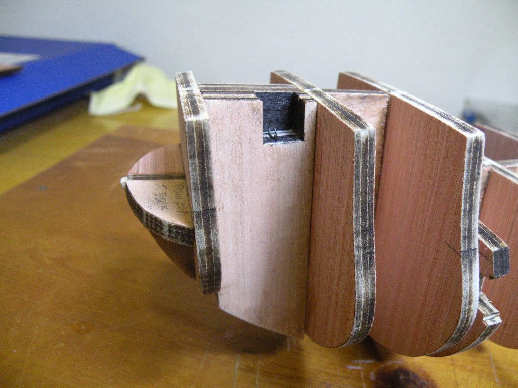
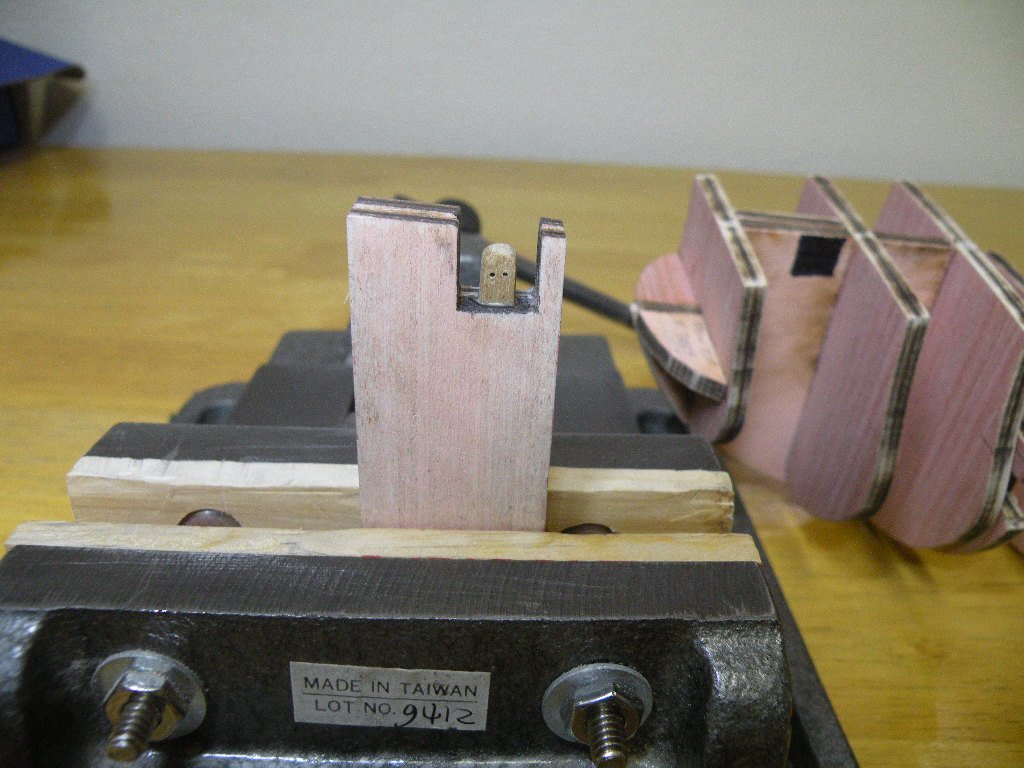
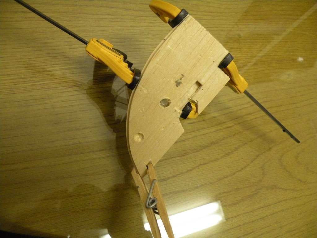
I wanted to simplify the whole thing, make something more authentic (though it won't be seen much) and stronger (stronger than gluing the tip of a wire to a block with CA). My stropped block would have been stronger but not as authentic. So I wondered why a wooden ramshead block couldn't just be made and glued to the bottom of the cut out. I did a mockup with a bit of 4mmx4mm walnut, drilling .5 mm holes to act as the sheaves. I liked it so I made the decision to go with it. Below is a pic of this block being glued onto the filler. When its dry I'll glue the whole thing into place. And that will just about finish up the framing of Mayflower.
-
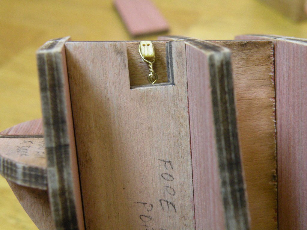
The last of the fillers, for the foremast required some decision making as to whether to go with the ideas in the manual or to improvise. There are three fillers. One goes on the starboard side and the other two on port. I decided I would glue the two port fillers together before gluing into the bulkheads. Essentially there are two of them cause the mfr did not want to supply a 3/8 inch filler block when everything else was cut from 3/16ths ply. So sandwich two together and you get the 3/8ths inch block. In the real world there was a 'ramshead block' just below deck level sitting on a cut out in this filler (in real life I don't think it was called a filler block). The ramshead block was accessible from a hatch above it, and had some standing rigging lines rove through it and up to a block above deck. The real Mayflower had a triple sheave ramshead block down there. For whatever reason the kit mfr did not supply a part for this but suggests that it be simulated by putting an eyebolt into the center of this cutout and hooking a double block to the eyebolt. We're asked to glue the wire hook to the bottom of the 1/8th inch double block. Later when we're rigging we'll string the line from above to the double block and hook it to the eyebolt before putting tension on it. Here's a pic of what it would look like -- admitedly ragged, but here I'm just experimenting. Mine has the hook stropped to the block and not glued to the bottom. Mine is also a slightly larger block (left over from previous build).
-
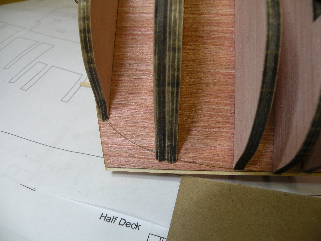
Before going into the story of the foremast filler and its eyebolt, I should point out what may or may not be an error in my placement of the bow's false decks. Notice that in the pics (with bulkhead E) when I used the reference lines etched into the bulkhead to position the two false decks, I placed the reference line at the top of the bottom 3rd ply of the false deck piece. I thought I was following the instruction pictures precisely. This position put the top surface of the false decks right flush to the top edge of the BF. Since there will be deck planks laid over this whole area, I thought (and still do) that it had to be smooth and flush across the surface. So a couple hours later when its dried and I'm futzing around with other stuff and looking at the photos in the instruction book, I see where the instructions explicitly point to positioning the reference lines at the bottom of the top 3rd ply. If I had done that the top of the BF would have stood proud of the false decks by a 1/16th of an inch. A lot of sanding down. On closer look at the instruction's photo I can tell that the decks and the BF are flush. So what gives? Did I make a mistake or what? Once again, I think this is a no harm no foul kind of thing. I have to believe that to plank the decks it needs to be flush and I can't believe the mfr would expect you to sand off 1/16th of an inch when there is no reason to. So I move on and will sleep soundly tonight.
-
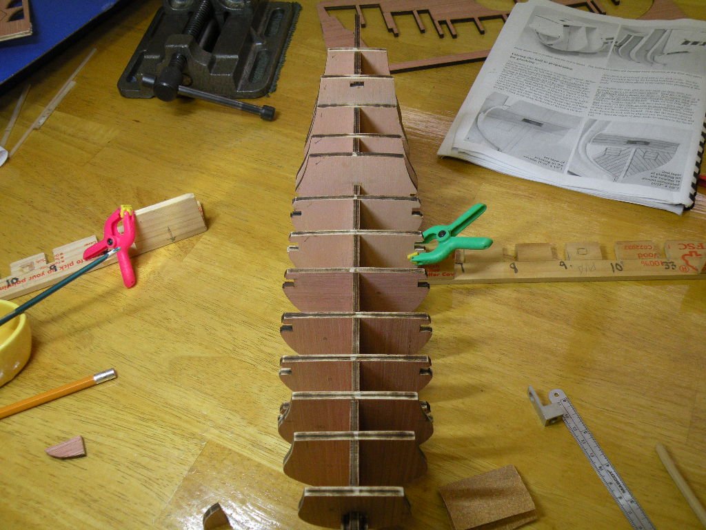
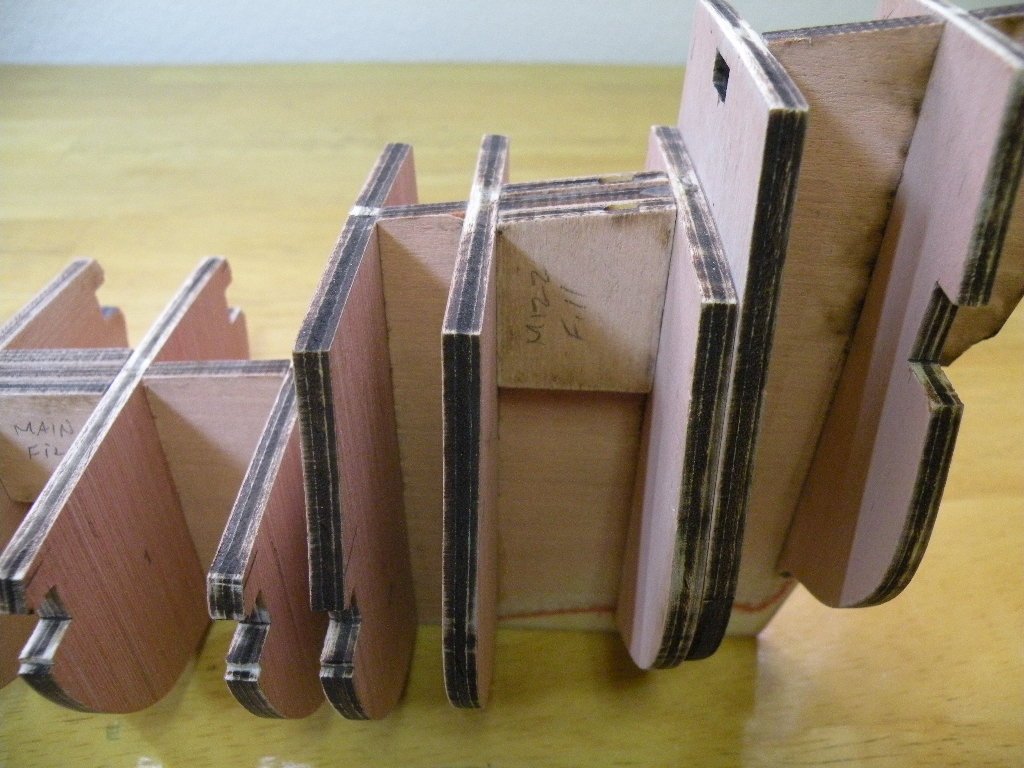
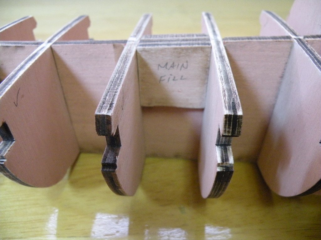
All the bulkheads are now glued in and the fillers (bow, main, mizzen and foremast) as well. All except for the two foremast fillers on port side which are a story in themselves. Putting these in was pretty straightforward and easy. Not much explanation needed other than to get them oriented correctly so the top edges match the slope of the bulkhead former. There is a slant to the BF which will create the slope of the decks from the bow and stern towards the center. Its not a huge angle but its possible to ignore it and think that the mismatch between the fillers' shape and the BF is just something that can be sanded down later. I guess it could. Probably wouldn't be any harm done; just alot of work and dust. So here's my work for today, starting with the completed bulkheads and running through the several fillers.
-
Lookin good. I agree that at this scale its hard to get trenails to look realistically small. I don't know how soft this planking is but I found on Bounty that the sharpened pencil made a good enough indentation -- enough to avoid drilling all the holes. And I'm just guessing, but I would bet that the wood filler is unnecessary if you paint the whole wall with sanding lacquer; maybe but not necessarily two coats. That would fill the holes without all blotch marks. You might also consider doing the staining first, then the trenailing and then the coat of lacquer. Will you be putting rings or something on the doors? A small eyebolt with a ring hung in it makes a good looking door knob (of sorts).
-
And speaking of distinguishing little pieces from one another -- when you get to putting on the bow fillers, there are two other pieces that look exactly the same but there is a very very slight difference in shape. These are the two bow false decks. Mine were not labeled either on the pieces themselves or the template, so I had to do a bit of testing this way and that. If you get them wrong there will be a bit of overhang beyond the BF that you might think just needs to be faired off. But no, when the pieces are right there is not much overhang if any. Note that the bow fillers go on vertically and the bow false decks are horizontal. And the fillers are not placed flush to the top of the BF, but are the thickness of the false deck pieces (I guess they are all the 3/16th ply) below the level of the BF top edge. So when you place the false decks on the bow fillers their top surface lies flush to the top edge of the BF and the deck will lay flat across the whole thing.
-
Thanks Richie and JB for the pointers. After I finish up the last bulkhead this morning I will look to doing (or not yet) all those little chores. Richie, I'm not positive of this but pretty sure that there are actually 3 fore mast fillers. Two for the port side as you noted, and I think there is one for the starboard side. Something for me to check on.
-
Hey Richie, that is a downer. I feel really bad for you seeing as my kit came so well. Do you have a scroll saw and would you attempt to cut your own PF (ha ha I thought you told me it was being called the 'profile former' so I went with PF. Should I switch to BF? Naw, from your pov now it should be BS)? I would do that for you if you say its worth while. Next build? Scratch build from swizzle sticks. Avoids all hassles. Only down side is you have to drink way too much coffee to finish the build.
-
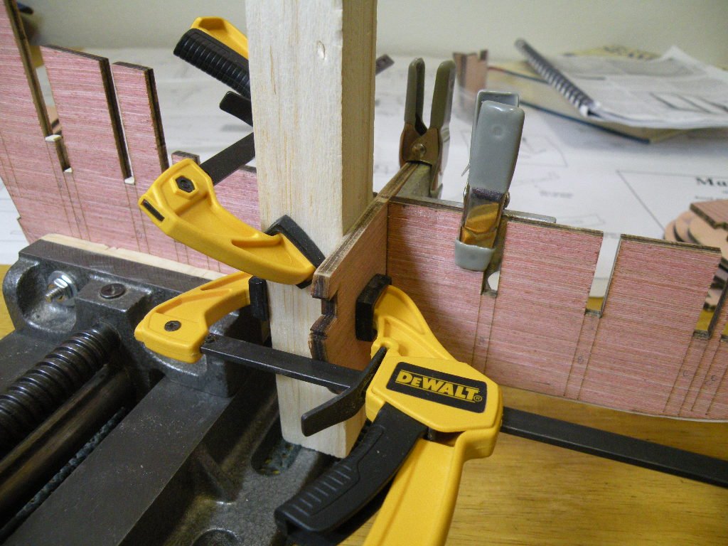
And no, I didn't smash my thumb with a hammer. Dog bit me 55 years ago and its never healed normally. Now I'm ready to start gluing in the bulkheads. As I type I have 2 of the 3 remaining bulkheads drying and I'll get the last one on later this afternoon. Again, I'm in no rush so I leave the glue to dry at least 3 hours before messing around further with it. This being Monday, I guess I've taken four or five days to glue in all 14 of the bulkheads. What's the hurry when you're having a good time. And, I will add, I am having a great time. So far, the experience of working with bulkheads v. frames and accurately laser cut pieces v. rather inaccurate ones is like night and day. Like getting a massage v. going to the dentist. Its just very satisfying to watch the pieces go together like a tight puzzle without all the adjustments, major and minor, that my first build entailed. There isn't a lot to describe as far as the process. I think the one question that most neophytes (like me still) have here is how much glue to use and where to put it. Maybe its just me?? I come from a general woodworking background so I continue to favor brushing on glue to cover the full surface of both halves of mating parts -- as opposed to spot gluing. In this case that means painting a very thin coat of Elmer's carpenters glue (yellow) into the edges of the notches and the little bottom of the notch, and in some places putting glue onto the flat surface of the bulkhead where the notch edges finally come to rest. The only thing I found was that this glue is pretty thick to begin with and in one or two cases it made for pushing the bulkhead into place very hard indeed. Even after the bulkhead had slid in easily but snugly on testing. I've lightened up on the amount of glue put down and that has worked well for the last 8 bulkheads. One thing is for sure: once the glue dries these are solid. They were all very squred to the PF to begin with, but I used various types of square things to clamp into the corner joints to hold the bulkhead while it dried. Again, overkill? Probably. But its a useful thing to do in building many other structures, so I like to be consistent in my process. Tomorrow I'll be starting on phase 2 of this build. So far I'm more than pleased with the results.


-
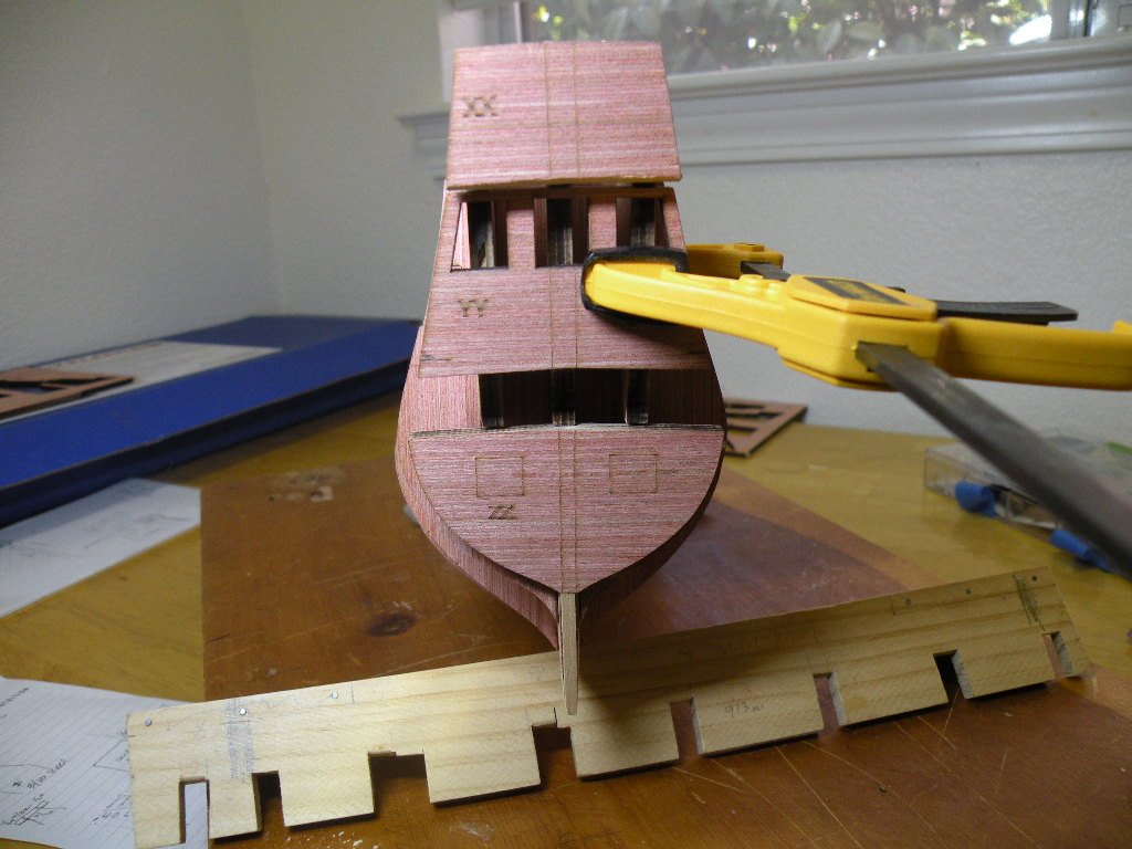
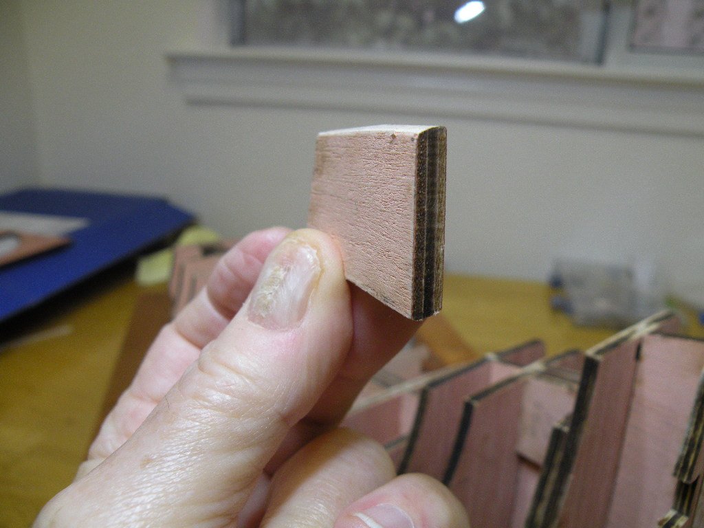
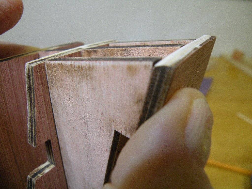
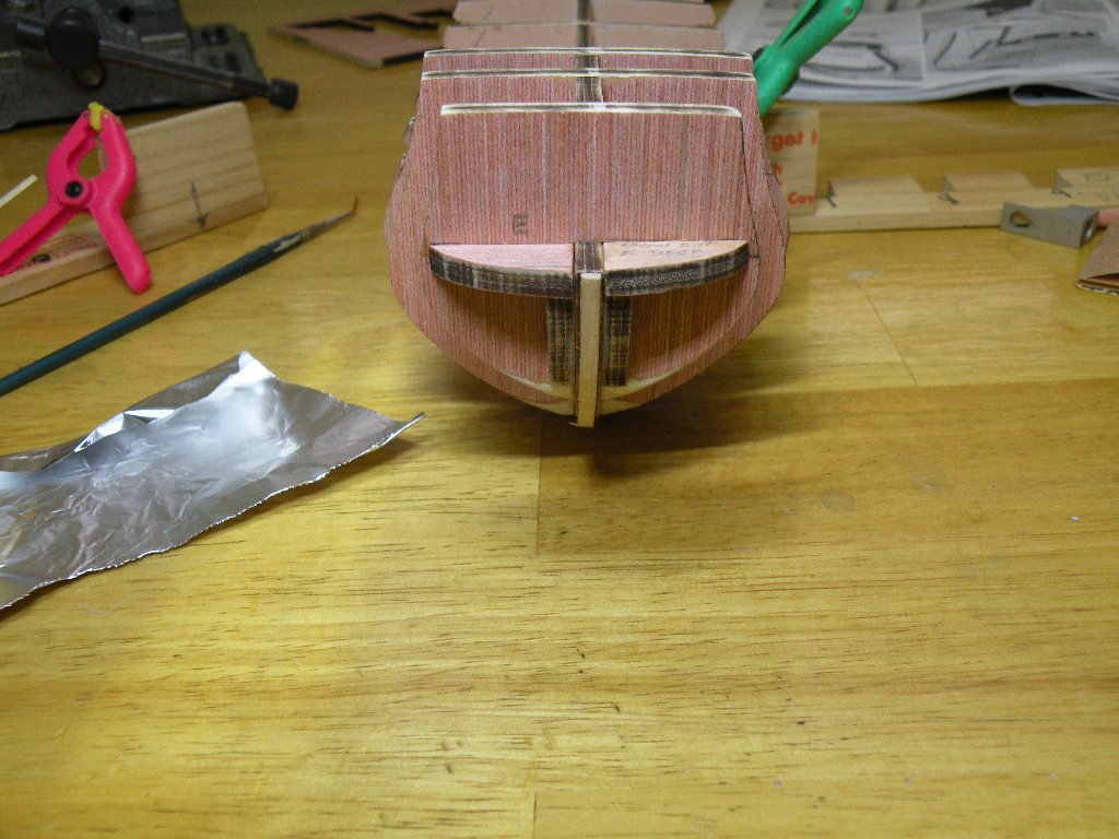
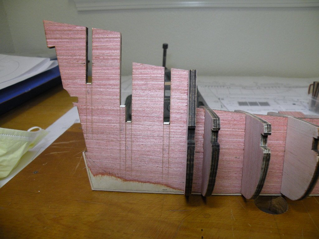
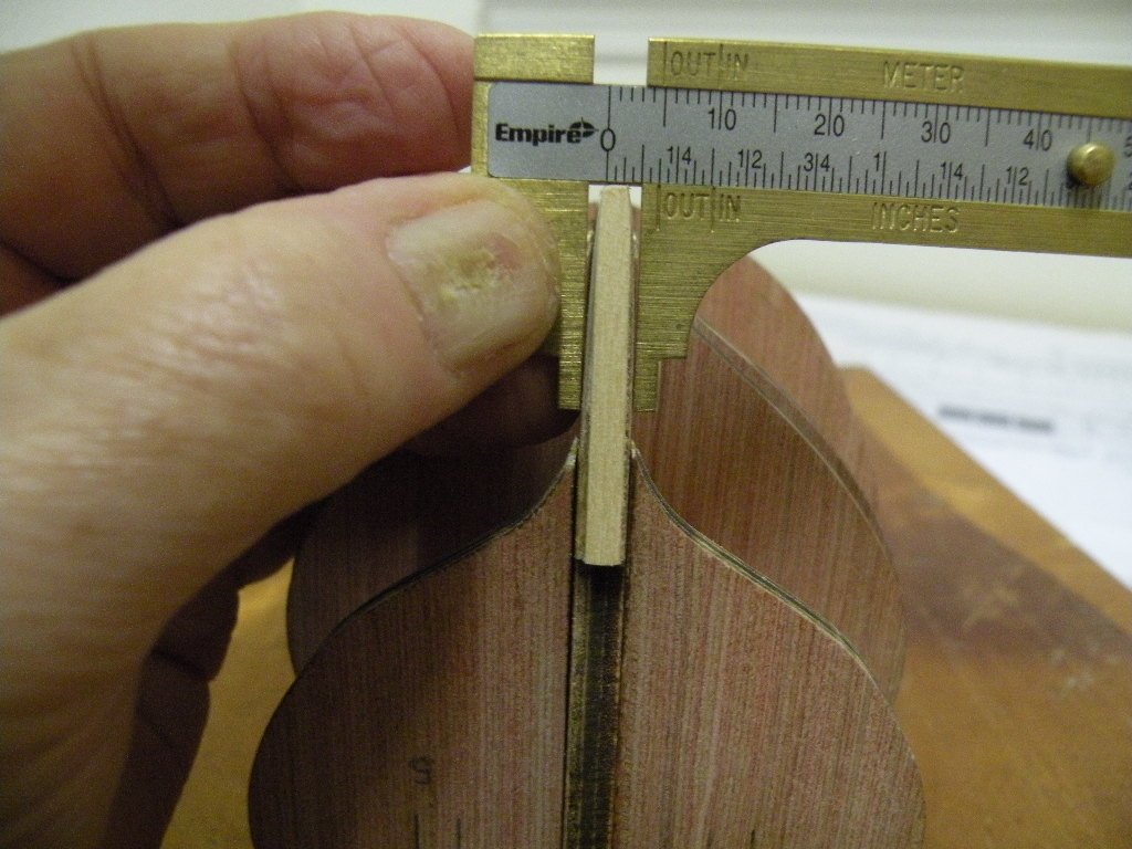
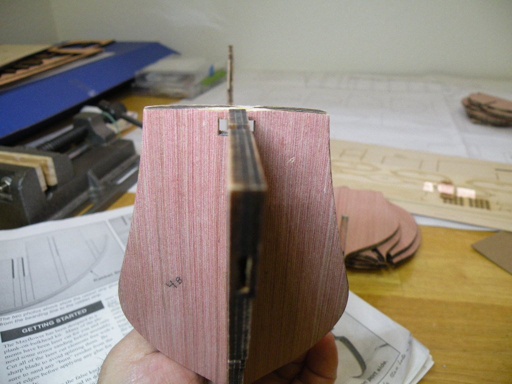
Going on with the build. After the rabbet strip was on it was time to taper the stern. Instructions said to taper from the bearding line to the rabbet and to taper from the 3/16th inch nominal thickness of the PF to 3/32nds. This meant take a bit off the rabbet that was just glued on. A little math therefore indicated to taper the rabbet 1/64th on each side. This is getting pretty tough to visualize so its important to just take small amounts of wood off each side of the stern in multiple passes, giving it the eye test frequently, and then dig into the rabbet just a little more on each of its sides to complete the job. I used a flat file for most of the job and a 320 grit paper to finish it. I think this is one area where perfection isn't required on this first pass cause later on when planking this area will be faired into the contour of the hull anyway. The first pic below shows the area to be tapered. Second is work in process. Third is my method of double checking my eye test.
-
.....guess I just hit a wrong key.... and African Walnut, I often left them in the pvc pipe soaker overnight. No harm and I was sure they'd be pliable.
-
Well I kill two birds with one stone... I soften up the wood and I prepare my pasta dinner. Seriously though, I told you before I tend to do things to excess just so later on I don't have to ask myself questions like: didn't I soak it long enough? or did I use enough glue? When I was soaking planking strips for Bounty (3mm in thickness)
-
Still can't get the hang of how to insert pix where I really want them or to caption them. Best I can do is do a write up and add the photos at the end. With this issue out of the way there are two more operations to do before gluing the bulkheads in. First the rabbet strip is to be glued to the bottom of the PF, and its to be placed precisely in the center of the PF along its entire length. The rabbet has to curve up the bow and I didn't think it could be done without first soaking the wood and pre-bending it on a jig. Cutting the jig from balsa on a Dremel scroll saw was a breeze. I've found that a trick to making small curved drying jigs is to cut notches at 90 degrees from where you will want to clamp down the wet strip, allowing a clamp to close squared up to the jig and not slip. I soaked the 3/16th rabbet strip for half hour in boiling water and put it on the jig. Let it dry overnight. Conformed perfectly to the bow's curve and glued on nicely.
-
So as I was saying. I wasn't sure exactly how the bulkheads should be positioned. Should the tops be flush? Should the bottoms of the two grooves butt up to each other? Or should the lowest part of the bulkhead (where it narrows to just the width of the PF) just be on the bearding line? There were reasons to think any of those might be the best, but in the end I decided to make the tops flush and I used shims to make that happen. In one case where the bulkhead was higher than the PF I filed the notch a bit deeper (filed both the PF notch and the bulkhead notch). Here's a shot of the shims. I used some .6mm deck planking from my last build and for the deepest one I used a bit of a Starbuck's swizzle stick. These just continue to come in handy. I'm thinking of building a scratch build completely out of swizzle sticks.

-
Continuing on where the last reply left off -- I've not yet learned how to insert a photo and then continue with the text. All my pix seem to end up at the bottom of the reply. I mentioned in my first comments that the PF was perfectly flat; no warpage. So the test fitting did not have any issues with that sort of thing. It was all a matter of sanding the notches a bit to get the pieces to slide into each other and still be snug. I found that sometimes it also helps to sand the surface of the bulkhead on both sides. This tiny bit of wood removal is usually enough to get the open notch to slide down the face of the bulkhead. Nerve racking when in the process you can't get the bulkhead out. Don't want to break that keel in half. Finger pressure is the only answer. Hands acting like one of those tools auto mechanics use to pull out gears and bearings. Now my big question was: Are you supposed to slide the two grooves together ALL THE WAY so the bottoms of the notches bang up against each other? Because if you do, I was seeing that in some cases the tops of the bulkheads stood proud of the top edge of the PF, and sometimes the tops ended up lower than the PF. I sensed that it is important that the tops all lie flush. Here's a pic or two to illustrate. Then I have to run to breakfast and get the day underway. But, like McArthur, I shall return. Note that photograph seems to magnify the problem. In the first pic below it looks like the bulkhead is sitting a half inch below the PF. In fact, the worst case was 1.5 mm.
-
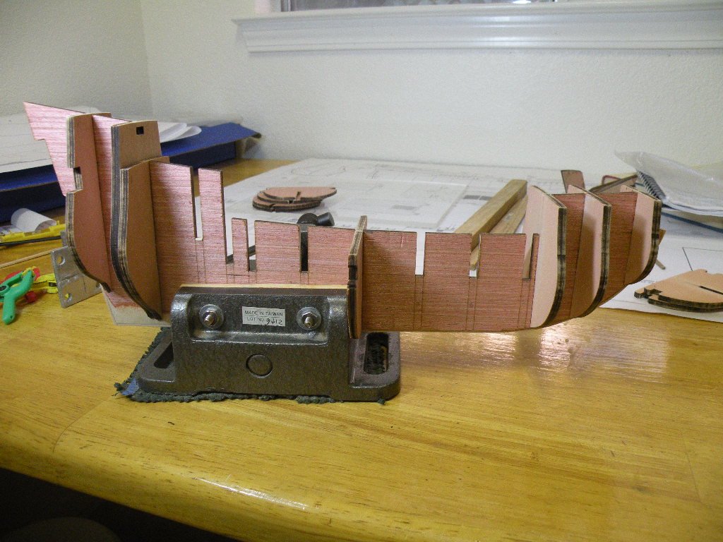
SUNDAY MORNING UPDATE 4-9-17 Nice time to sit quietly, sip a steaming latte and contemplate and report on what's been accomplished over the weekend. I'm now in the process of gluing in the 14 bulkheads (completed 8 of them and hope to do the final 6 before going to bed tonight). Here's a brief run down on how the process has gone.... To begin with, the first step is always popping the parts out of their templates. To me this is the most onorous, boring, time consuming and even fatiguing process there is in kit building. For the PF and bulkheads its always the thickest plywood (in this case 3/8ths) and I've always got the fear of snapping one of these off. I use a #11 blade which I know to be quite sharp (just purchased 100 new ones from MicroMark for $21) but my handle is just an aluminium tube that I've had for 40 years. Probably a good handle would reduce the fatigue. So this step took quite a while but in the end, with new found patience, I broke nothing and got all the pieces removed. Next was to remove the 'char.' I noted to RichieG that all the pieces and the template itself looked like it had gone through the London Fire. Seriously discolored. Not just the cut edges but even the flat surfaces (not however the one good side of the plywood with reference marks). So began the sanding off of char process. Question then became how much to sand off? I've learned from the past that I can get pretty aggressive and actually take off so much wood that I later have to compensate for it. I wanted to be sure I left the shape and dimensions of these bulkheads exactly as cut. Its important to visualize that the top edge of the bulkhead becomes the cross beams for each of the decks. So they have a slight concave shape that needs to be maintained. I decided after consultation that removing char does nothing more than prep the wood for gluing (I'll stand corrected if this conclusion is wrong), so it only needs to rough up any "shine" or slick areas -- in other words, open up the pores so glue can adhere better. No need to sand darkened areas down to new wood. That would be far too much. TEST FITTINGS So now my PF and bulkheads are ready for test fitting. I've never thought it worthwhile to invest in one of those thingies that hold the PF (or false keel) in place and purport to guarantee that the bulkheads are squared up. Instead I use the vise that I have from my full size Delta 15" drill press. It can be seen in some of the pix I'll attach.
-
Good to have you all aboard.
-
LOL Richie. Probaby cause I talk too much in my sleep.
-
Brought to you by popular demand.
-
This is the official start of my Mayflower build log though I have been posting pictures and comments for about a week on RichieG's log. Thanks RG for loaning me the space. I'll dispense with all of the photos of the box and its contents. This is the Modelshipways kit with the great 52 page instruction booklet by Chuck Passaro. Thank you Chuck for including this...its wonderful and actually was the deciding factor in my purchasing this kit. The booklet can be viewed on-line before buying the kit for anyone interested. http://www.historicships.com/TALLSHIPS/Model Shipways/Mayflower/MS2020-Mayflower-Instructions.pdf The kit arrived in 2 days even though I paid for 7-10 day shipping. Nice people at Model Shipways. I did a complete inventory of the parts and wood supply and was amazed at what accuracy everything was supplied. If there are supposed to be 80 pieces of planking, there are 80 pieces. Not 79 or 81, but 80. Same for stuff like cleats and rings and pins. The only thing I didn't count was tacks. I trust there will be enough. Now it remains to be seen if MS has allowed for some breakage and loss overboard. We shall see. My only disappointment is in the metal platforms or "crows nests" that are supplied pre-cast. They're a bit tacky. But MS probably knows this and the instructions detail how to scratch build your own from wood. Which I plan to do. Same for a capstan. Its going to be interesting working at 1:78 scale and in fractions. My only previous build, Bounty, was 1:48 and measured in metrics which I got very used to and find so much easier to use at these small sizes. Whatever happened to Jimmy Carter's plan to put the country on the metric system. Was supposed to happen within a decade. I guess we Americans don't give up our old ways easily. There are 4 sheets of plans which, along with the booklet, seem detailed enough. Without the booklet I would say they would be not quite sufficient. My only worry on receiving the kit was whether or not the profile former (used to be called the false keel), which from here on I am going to abbreviate as PF, would be warped. My Bounty false keel was a bit warped and I stubbornly pushed on with the build without attempting to get a replacement from Artesiana Latina. I think if I had waited I would still be waiting and that was 3 1/2 years ago. I know RichieG needed to return his and today I learned its either arrived or on its way. But mine is flat as a pancake if not quite as fluffy. So overall, my satisfaction with the quality of this kit and the bang for the buck is A+. I was looking for a model of historic importance that was not as large as Bounty (who has that kind of shelf space?), has some rigging but not nearly the degree of complex lines as Bounty had (and which in the end caused me to stop the build), and which I could have fun building with a lot less complications, research and questions. I think this Mayflower is going to accomplish all that.
