


Captain Al
-
Posts
613 -
Joined
-
Last visited
Content Type
Profiles
Forums
Gallery
Events
Everything posted by Captain Al
-
Looks good. All squared up with legos. I looked on line and will probably pick up a can of them sometime soon. Looks like they would be a great substitute for all the square wood blocks that I keep around. I also keep a bunch of little wedges. Keep that in mind when you are filing or sanding bulkheads and would like to stabilize it but don't have room for a block or lego. I slip a wedge down in between them. Now that you bring up the subject of the rabbet at the bow.... first off, I think I do the same thing; try one way or another to make a technique a bit easier or get a better result and in the end the tried and true way in the instructions are just as good. But it provides experience and that's really what we're after at this point. Now, as for the rabbet...I'm thinking of the planking now and with that rabbet strip on the bow it seems that the planks that wrap around the bow are going to have to hit that rabbet. Means they have to be cut perfectly or else they will need to be started at the rabbet and wrapped back in the direction of the stern. What I did on Bounty was always to leave plenty of overhang (there was no rabbet) and then cut the planks when dry. That had the advantage of being able to rubberband the plank to the hull on the opposite side so the bend was held tight. This is just a first planking so I suppose the joint at the rabbet doesn't have to be perfect.
-
OK, glad to hear the games are on. Interesting though that my pinkish BF was perfect and it was those that are bad for you. I'll be glad to oblige you and slow down. It feels like I'm at a snails pace anyway since getting on with the fairing. Today I finished gluing on the last deck (the big one) and was looking over the next stage (planking the counter) when I remembered I had wanted to fill some gaps here and there with wood filler. So I did a bit of that. I'm using Durhams, a powder that mixes up really nicely into any consistency you need and dries quite hard but is still very sandable. After a bit of that I got to thinking about filling the bow with balsa filler. So I began a new career as a wood carver. I'll post on this in the morning with some pix. I did one side and I think its good enough to go ahead and do the other and use them.
-
I just wanted to pop in and offer my heartfelt congratulations and admiration for your completed build. As a newbie its even more impressive that you made it happen. It looks great and you should be proud.
-
Yeah, I've been PMing him several times this past couple weeks and his answers, while great, have been short and sweet. I don't know what he does during the day but he is very attentive. This becomes a moot point though cause I went ahead and did the shaving of about 1.5mm on each side of 4b and then faired a bit more. I did the same thing as you did before I want ahead and did it; I poured over the instructions and plans and just couldn't find any words or drawings that would lead me to the opposite conclusion. In fact, if I recall correctly (duh, it was all of 3 or 4 hours ago) there is a drawing from above of the ship which, when measured shows it at 50 mm -- and nothing outboard of the bulwarks and planking that might require this additional mm or so. My conclusion, til told otherwise or til I discover I really messed it up, is that a lot of fairing is required there. Why? Only Chuck would know. After gluing down this poop deck my feelings have been reenforced. It all follows a nice curve to the stern and the bulwarks will fit snugly up against the deck edge. Not much pushing and pinning of the bulwarks will be needed. So I think its good. Thank you for taking the time to look ahead and semi confirm my thoughts. I ought to pose these questions late in the day or evening so I don't grow impatient and begin the day's work without an answer.
-
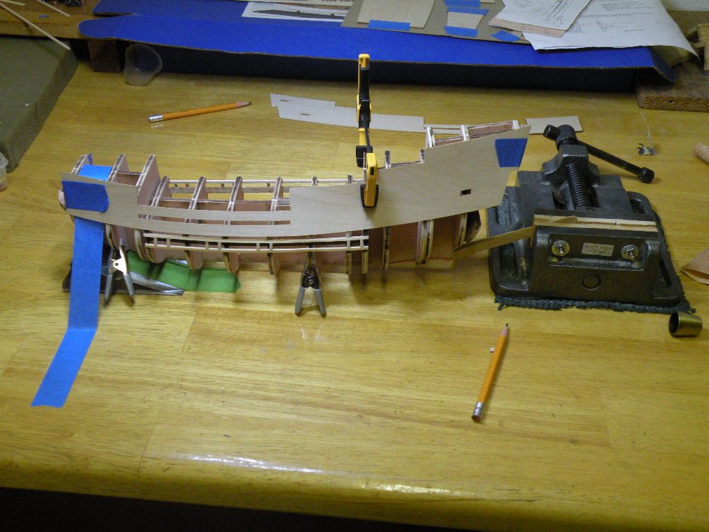
Yes, I must say things are falling into place quite well. Probably due more to Chuck's design and attention to detail than to my skills. The one big difference in fairing Mayflower v. Bounty is the solid bulkheads v. Bounty's open framing. Not only am I able to sand and file with more confidence of not breaking one of these bulkheads off, but the visualizing and use of battens seems to be so much more precise. Anyway, I got to the point this morning where I was satisfied and willing to call it quits with fairing -- at least until I was actually planking and maybe would have to make some minor adjustments. So I moved on to the gluing on of the 4 deck templates. The first two went on without a thought. The only issue was how to hold down the slight concave shape to them. It is so slight and the template ply is so thin that masking take is sufficient. So I get to the poop deck and that's when it got interesting. Laying the template down on the top edge of the bulkheads I was surprised to see that it fit fine onto #5 and stern frame XX. But, and you can see this in the picture, frame 4 (or maybe 4b) is significantly wider than the deck template. I took a bunch of measurements off the plans and convinced myself that the ply template is correct. Its 50mm wide. The bulkhead though is more like 53 (off measurements and before fairing). I'm still giving this some thought and will proceed after lunch, but for now my conclusion is that the bulkhead simply needs to be faired a lot more. Normally the fairing process has just changed the contour or angle of the bulkhead edge. Usually either the fore or aft edge of the bulkhead remains as it came off the template while the other gets cut away to the proper angle. But in this case it seems like not only will the angle be put into the edge but the width of the bulkhead from side to side will have to be reduced from the 53mm to 50. 1.5mm on each side doesn't sound like much but when all the other bulkheads were the exact width of the deck template that goes on top, it has given me pause. But what else is there to do but get out the file and start rubbing away the wood? My last check or concern was (is) what this will do to the shape overall of the bulwarks back at the aft end. The interesting thing is that it seems like it will reduce the angle from bulkhead 4 to the XX frame, making the lay of the ply template easier, but it will also reduce the amount of convexness (is that a word?) to frame 4 and that will also make the gluing up process easier. Do you see any other solution but to go back and continue fairing bulkhead 4 until it matches the deck?
-
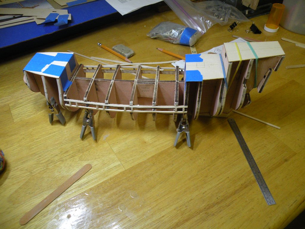
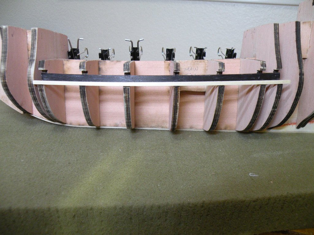
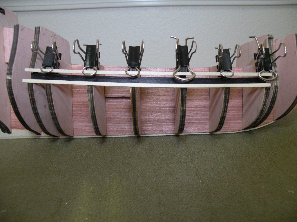
So the fairing continues and is probably reaching its last day or so. With Chuck's guidance and encouragement the issue of how flexible the bulwark templates will be and how to hold them tight against the frames has pretty much been put to rest, and to the test. I did some practicing with scrap ply (from used templates) to see how easy or hard it would be to pin those templates down. I like to know going in what size pin and what size pilot holes to use. I also realized I would have to stabilize the ship so I would have two free hands. After several iterations I found that a .5mm pin with 5 mm length would do the job. The pins that the kit supplies are 10 mm in length and wiggle too much when held in pliers to push in. (has anyone bought those pin inserting push pliers? Worth it???). I've got lots of 5mm pins on hand but if not I'd just snip some 10s down to 5mm. After some more sanding here and there I got the ship anchored down so I could tape the bulkhead template in place. Irony of ironies, I'm pretty sure that for this first application (putting the templates on temporarily for the purpose of drawing reference lines for the first line of planking) I won't even have to pin them. You can see in the pix below that this first one sits pretty tight and I can use tape to secure it long enough to get the lines drawn. When doing this step, make sure that the lines drawn under the template are drawn when the template is being pushed into the convex shape. If you don't there will be about a .5mm difference when you put the template back on permanently and do push it in flush to the convex frame. Doesn't sound like much, and probably you could overhang the lowest plank on the template by that much to meet the top line of planking already on the hull, but why not be aware of this? So here's the evidence of progress:
-
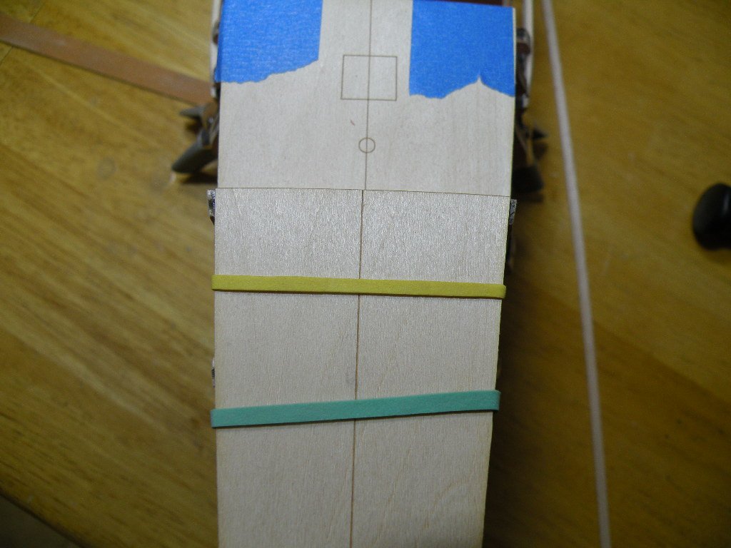
Looks that way Richie but like I said, pix don't tell the whole story. Deceiving for some reason. I saw that as soon as I posted the pic. So if you look at the pic again you'll see that the char remains on both 4 and 5 on the left side. Meaning, wood was taken off both edges on the same side. You should also note that this is the top edge of 4 and 5, the edge that the poop deck will sit on. It is not the side edge, which is the edge I am referring to in the post on which the bulwark template rests. Kind of an apples to cherries comparison. But your observation has made me go back and look more closely at the fairing so far and what I found, and what I think causes this optical illusion, is that I haven't faired frame 5's edge at all up high where the bulwark template will press against it. So this needs to be done and then, I believe if I took the same picture it would capture the fairing going the right way for both the top and side edges. I consulted with Chuck and he thinks it'll be easier than I think. I believe he's right and when this edge is faired some more it'll fall into place just enough better to eleviate my worries. But just in case I am thinking about filler blocks here and there and various clamping methods. Chuck suggests maybe rubber bands which always work well in wierd places. And of course there is no reason not to use pins while the glue dries. In a pinch, there's alway CA glue in strategic places as a substitute for a clamp.
-
Hi Maturin52. Thanks for popping in and I'm glad to have been of some help in your Bounty build. As you know then from the end result, being creative and inaccurate in my mind does not detract that much from the end result (at least for those who aren't concerned with historic and technical details). This kit, from MS, is like night and day from AL's and I would recommend it to you for some time in the future. It sounds like you are jumping from the frying pan into the fire, but I can understand the reasons.
-
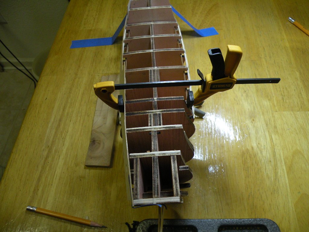
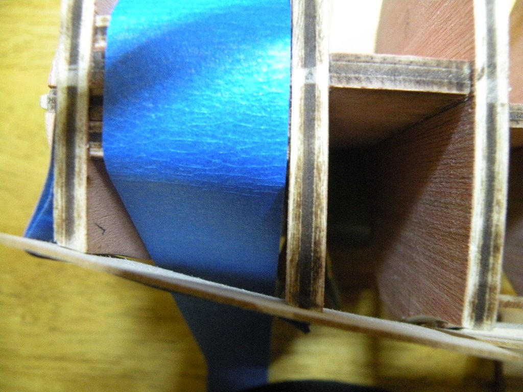
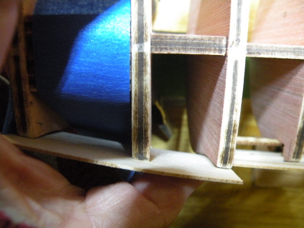
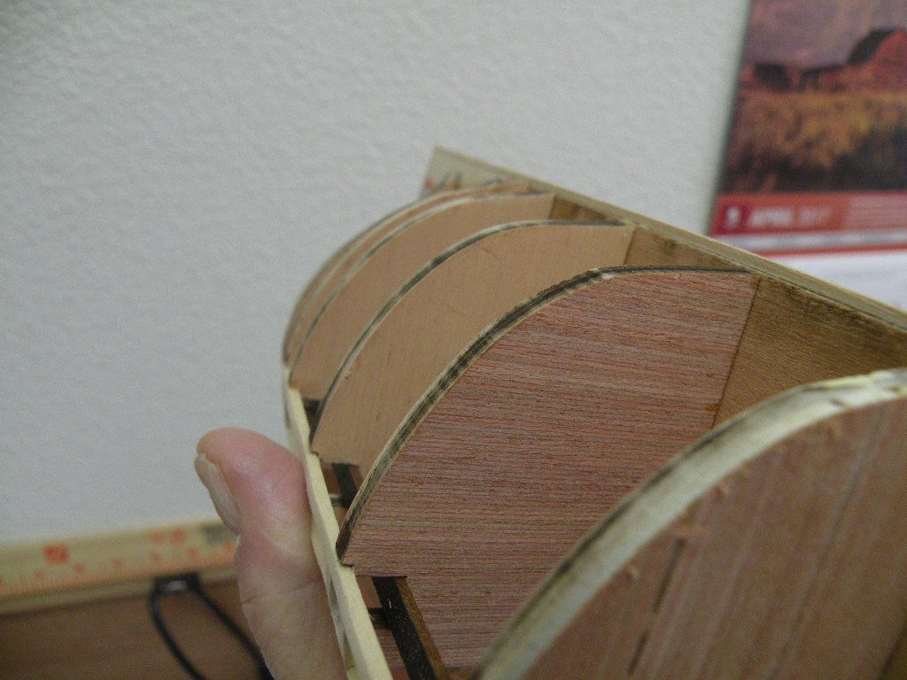
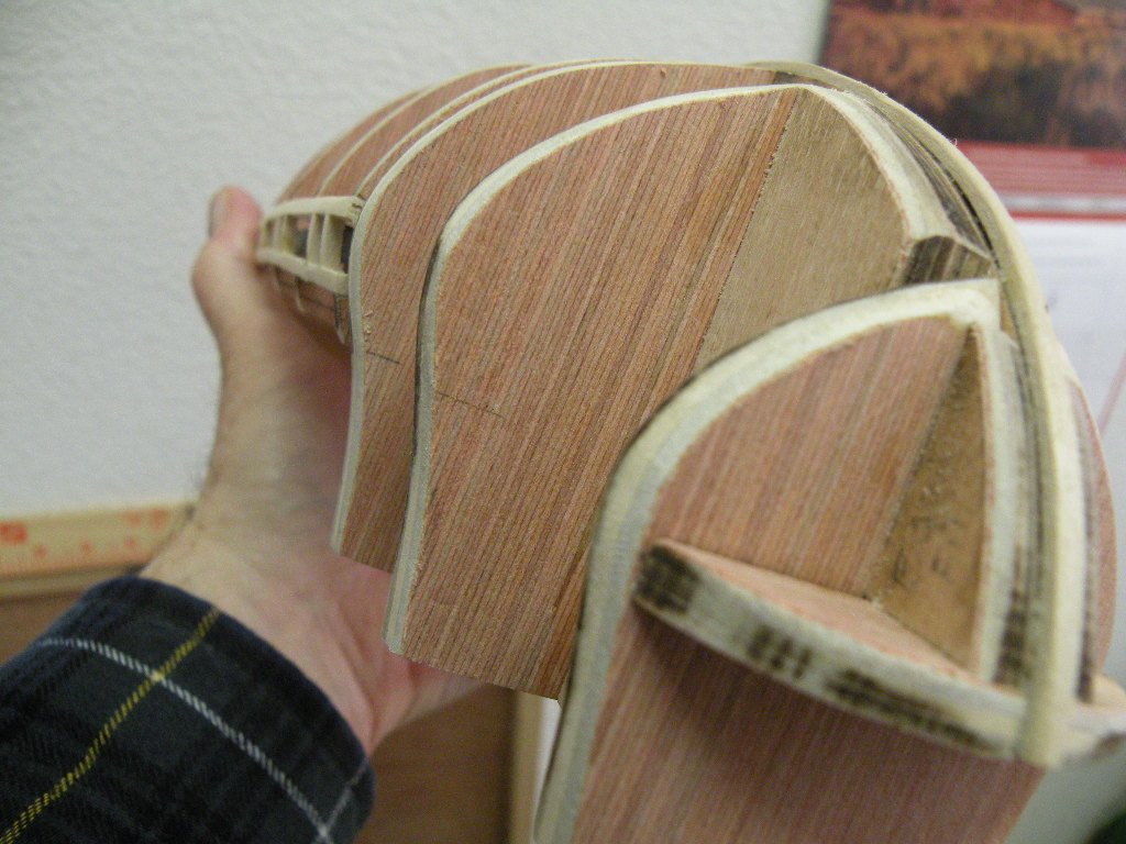
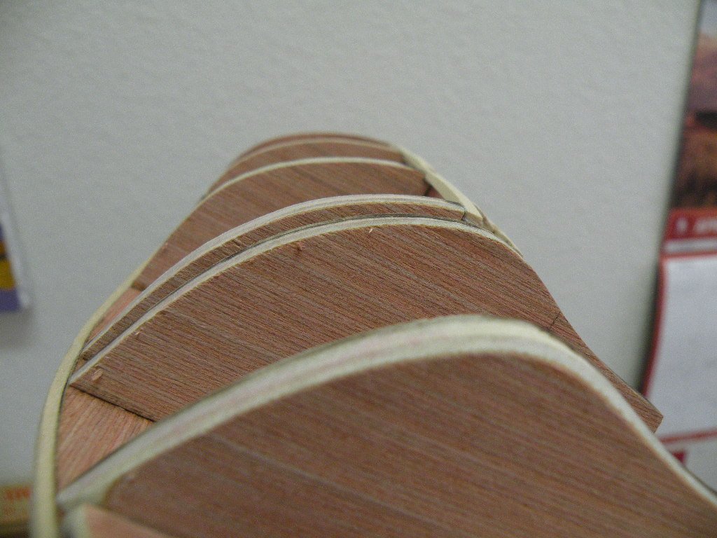
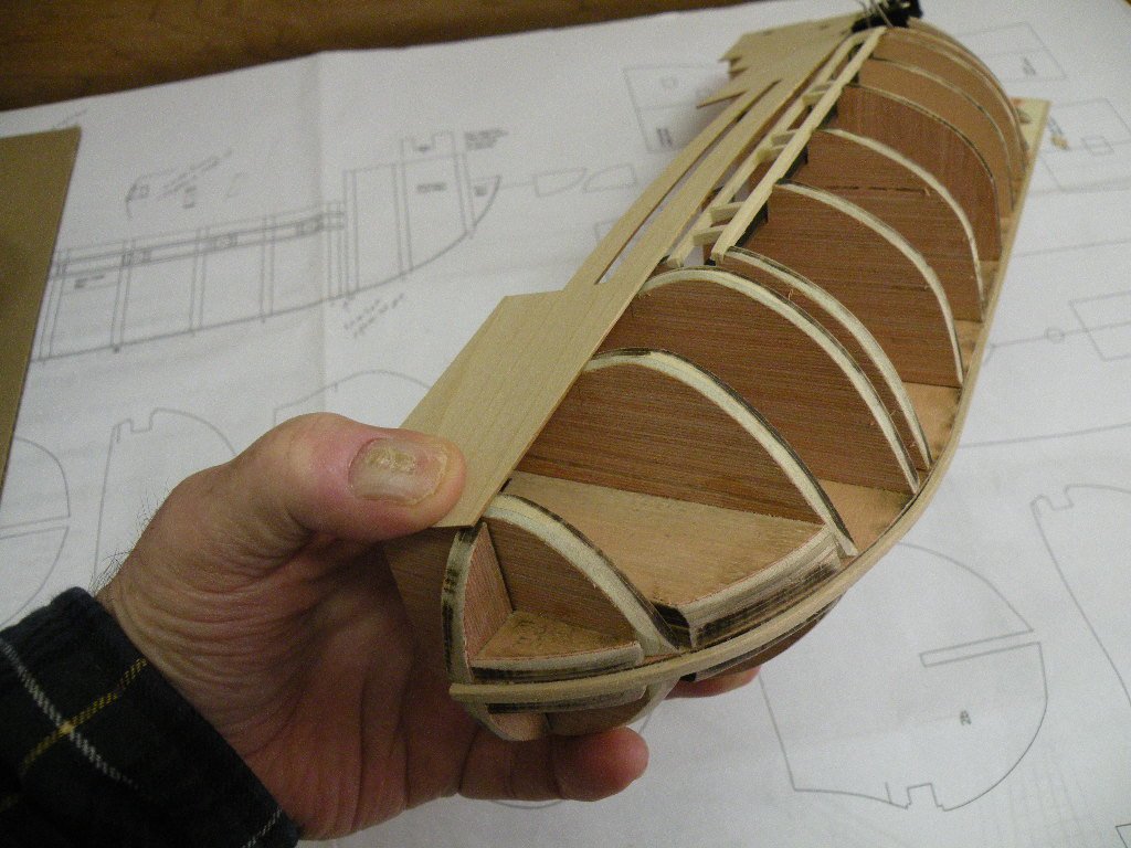
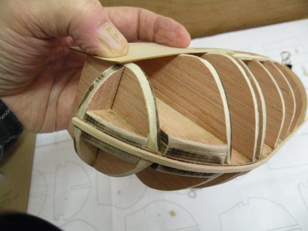
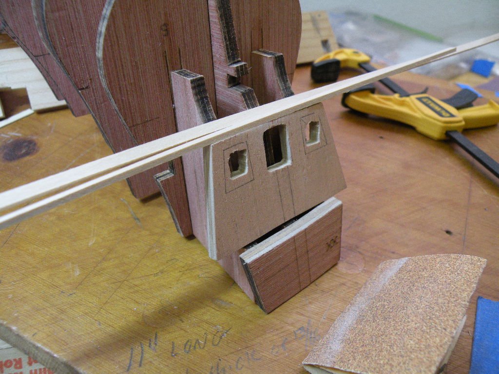
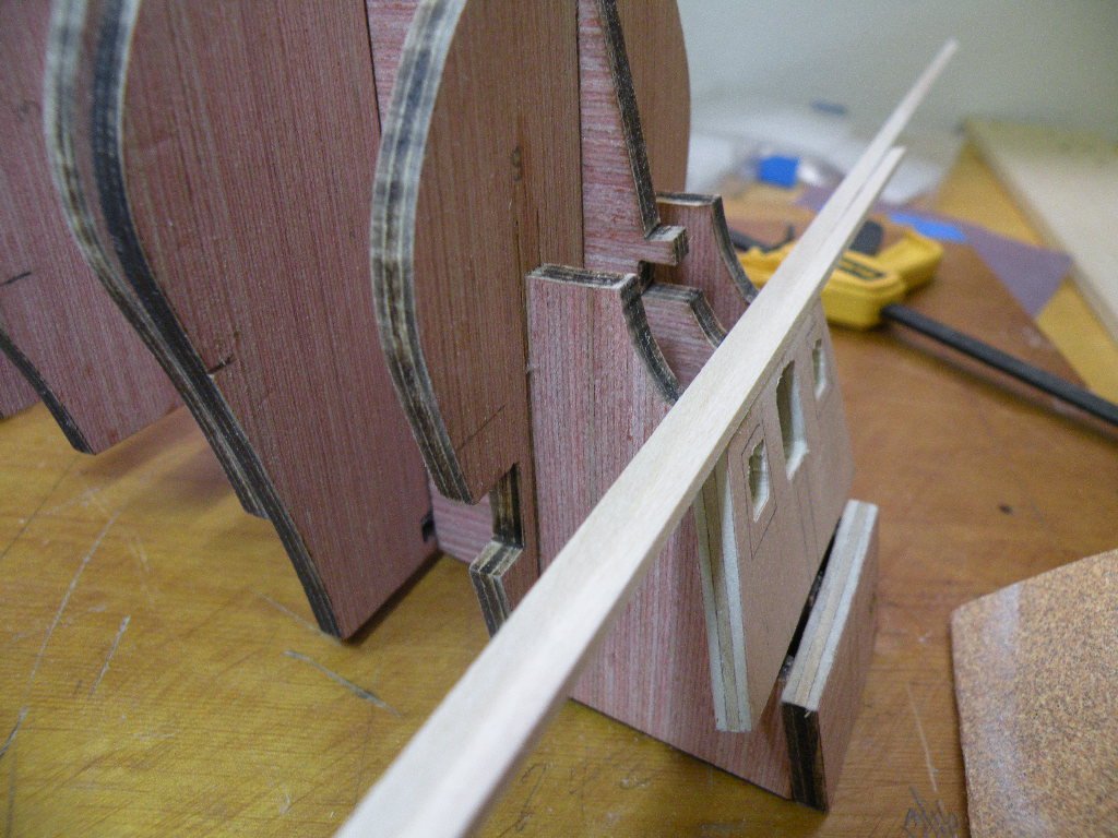
I'm hoping someone can shed some light on this dilemma which is giving me fits. From the three pix above that show me holding the bulwark template up against the frames, you can probably tell that the shape of the last couple frames on the bow and stern (not so much on the stern) goes from concave to convex. The pix don't show though how it seems to be necessary to press the template (made of 1/32 ply) into the convex part of the frame in order to maintain that 'flowing' shape to the hull. The template is pretty flexible at 1/32" but later on the instructions tell us to plank the insides before permanently gluing to the frames. I'm wondering how all this should be done. First of all I'm wondering if I'm correct and the convex shape of the frames should be maintained -- or should it be 'faired' away? I have to believe it stays as convex; no way to fair it flat. So I'm wondering if the planking on the template will make it too thick and inflexible to press into the space? The planks of course run laterally so they will give some. And the outside planking won't be put on until the template is securely in place, so those planks aren't an issue. Just seems that a lot of thumb pressure is already needed to push the template into the right shape, so how will that pressure be maintained until glue dries? Is this a spot where pinning would be useful? The pins would have to be taken out or their head's filed down before the final planking would lie flat. I haven't found a clamp that would work well. Pressure needs to be spread around a wide area while a clamp usually is pretty focused. Any suggestions will be appreciated. This is the first time I've come up against a problem like this. On my other build I planked the convex areas with narrow width strips (the usual sort) and that was what made it possible to do the inside curves. That's easier than getting a piece of ply to sit down and stay down on an inside curve.
-
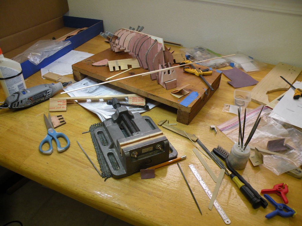
Here's a few snapshots of work in process. For whatever they're worth. This is one instance where a picture does not tell 1000 words.
-
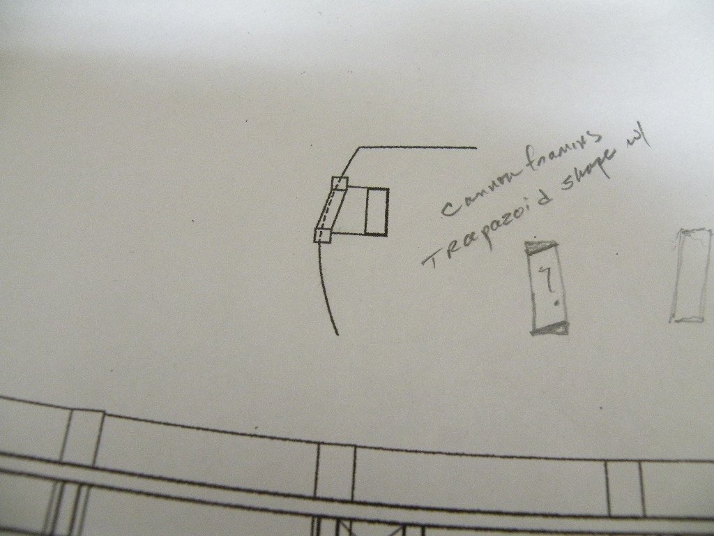
Tell me about it. Its just not fair! We shouldn't be made to do such things. Seriously though....Tiger man, do you have some ideas for these cannon that you're not sharing? I'd like to see them if you do. Only 'fair' that you share.... As for my idea Richie -- can't agree more that it is more work. But they would be seen if you looked very closely into the open ports. Maybe with a mag. glass? I haven't really taken size into consideration yet. As for the work, its the kind of modeling work I enjoy the most so that doesn't deter me. I would probably just do one or two anyway and let the other ports remain closed and empty. Now as for this fairing business. Its very frustrating never knowing when enough is good enough. Each time I look at it and put battens around it another high spot pops up. But for me, its distinguishing between a high spot and a low spot. This may sound dumb but when I sight down the barrel of a batten and all seems fine except for a bit low on one frame, its hard to know if that one frame should be shimmed or if the previous frame is a bit high. Since I've been pretty careful not to be overly agressive and I'm usually using a sanding stick that spans several bulkheads, its usually safe to say the one is still a bit too high. Clearly its the bow and stern that are hardest. Its surprising how much wood needs to be taken off. I have to keep referring to the on-line pix to assure myself to keep going. I jumped a ahead of myself today and took out the bulwark templates even though I know I'm not nearly ready to pin them on and mark them etc. etc. Revalation: these make the best 'battens.' At least for the upper structure. You can see immediately where they aren't going to sit flat, and more importantly, how much it seems possible to curve them around the bow. These are pretty delicate pieces of thin ply so unless the frames are well faired I think the template could snap in two if forced to make too sharp a bend around a frame. This was my clue today that I had lots and lots more filing to do.
-
OK, it took me awhile to see what you've been saying. I think that would work. Its too late for me now, I'm long done with gluing in those pieces. The only thing is, now that I'm doing the fairing, a great deal of this wood is taken off. In some places I've had to sand it down to maybe half its thickness. So if they aren't sitting in the notches it could be a problem. I say could be, not will be. You just don't want these strips to sit so proud that you'd have to sand them to a sliver. Perhaps in combo with your idea of a spacer, you can make small adjustments to the notches and make it all come together perfectly. But quite honestly, I wouldn't go to a ton of work. These all get planked over and its the port frames themselves that will make it visually OK. I plan to make my frames the size of the smallest gun port that way they'll fit in all of the ports. The outside part of the port lid has enough overhang to compensate for the larger openings. Remember, I'm talking about a half mm of difference from the largest to the smallest. Or, the ones that are not fitting well (if they all don't) can be the ones that are put on open. BTW, I'm not particularly in love with the way the lids are made to be kept open. Also not liking how a cannon is just stuck into a hole in that backing strip. I'm thinking of how to put down a floor in the port and put the cannon on little carriages and put them on the floor. But like Chuck says, this wasn't a warship and maybe the whole thing will look best with all the ports closed. I'll be posting some pix of the fairing pretty soon. I still have several days of this ahead.
-
Hey Richie, I think we are confusing each other by talking about different dimensions. You seem to be talking about the inside width of the gunports, from left to right. I agree that these should be consisten and your idea of a temporary spacer to position the frames is a good one. The gunports, by my measurement of the plans, should be 8 mm apart (inside dimension). So the spacer you suggest needs to be 8 mm wide. Now, for the spacer to even sit inside the horizontal strips it needs to be 1/4" high. This is the dimension that that is difficult to make consistent because despite all the effort I put in to position these horizontal strips correctly, they don't run as perfectly parallel to each other (at a 1/4" distance from each other) like a train track does. So its not your suggested spacer that's the problem, its the actual vertical frames. The have to slide snugly into these parallel horizontal strips, and at the size we're working with even a half mm can make them either too big to get in there at all, or too small and they are hard to hold steady and squared up til the glue dries. Now the spacer might help with this issue a little bit. Given that if they were slightly to loose they would have this spacer to lean on and that might help (note that pva glue is usually enough to fill the gaps if they're less than .5mm) but if you've cut these frames just a tad too big (top to bottom) and they won't slid between the horizontal strips, then the spacer isn't going to help with that. Having read this, I wish I'd used a spacer like you suggest just to keep the port openings consistent at 8 mm wide. I've finished the work today and in the end the ports may vary in width by .25 to .5 mm. But that don't worry me none cause I will either file/sand the inside of one or the other or both of the frames to make them exactly 8mm apart, or I will build the gun ports one by one and cut those inside pieces so they fit into a port opening that is like 7.75 mm instead of 8. Believe me, .24 - .5 mm is almost impossible to recognize with the naked eye. At least not by the octogenarians that will be viewing my Mayflower. Now your young eyes may be different.
-
Just to say thanks to all those who've stayed aboard. Happy Easter Sunday. And Joel, can I blame it on my cheap tools?
-
But wouldn't the spacers have to be of different thicknesses? The gap between the upper and lower frame is not consistent across its full length. Some places its a bit more others a bit less than the 1/4inch its supposed to be. I think the best solution (now he tells me) is to even more careful than i was in laying down those two strips. But that would be very hard to do given the vagaries of those little notches they sit in. Which, btw, takes up back to the topic of "how much char to remove." My thinking is that I may have altered the notches a wee wee bit (but enough to make a difference) by being over zealous in taking off char. Lesson learned for me is that while I might take char off edges, I will never touch a notch with a file or sand paper. Especially if the kit mfr seems to have done a very good job of laser cutting in general. Remember that funny caliper I described to you? Essential for measuring the inside dimension (height) between the strips at the point where the frames will fit.
-
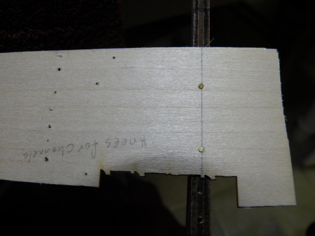
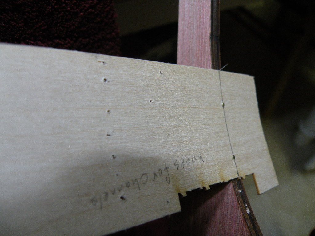
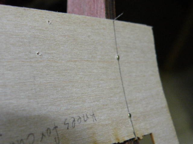
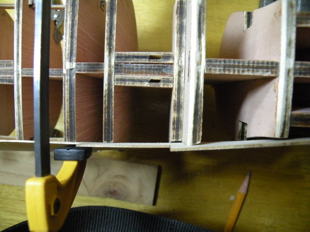
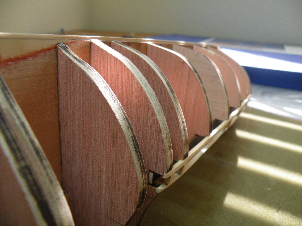
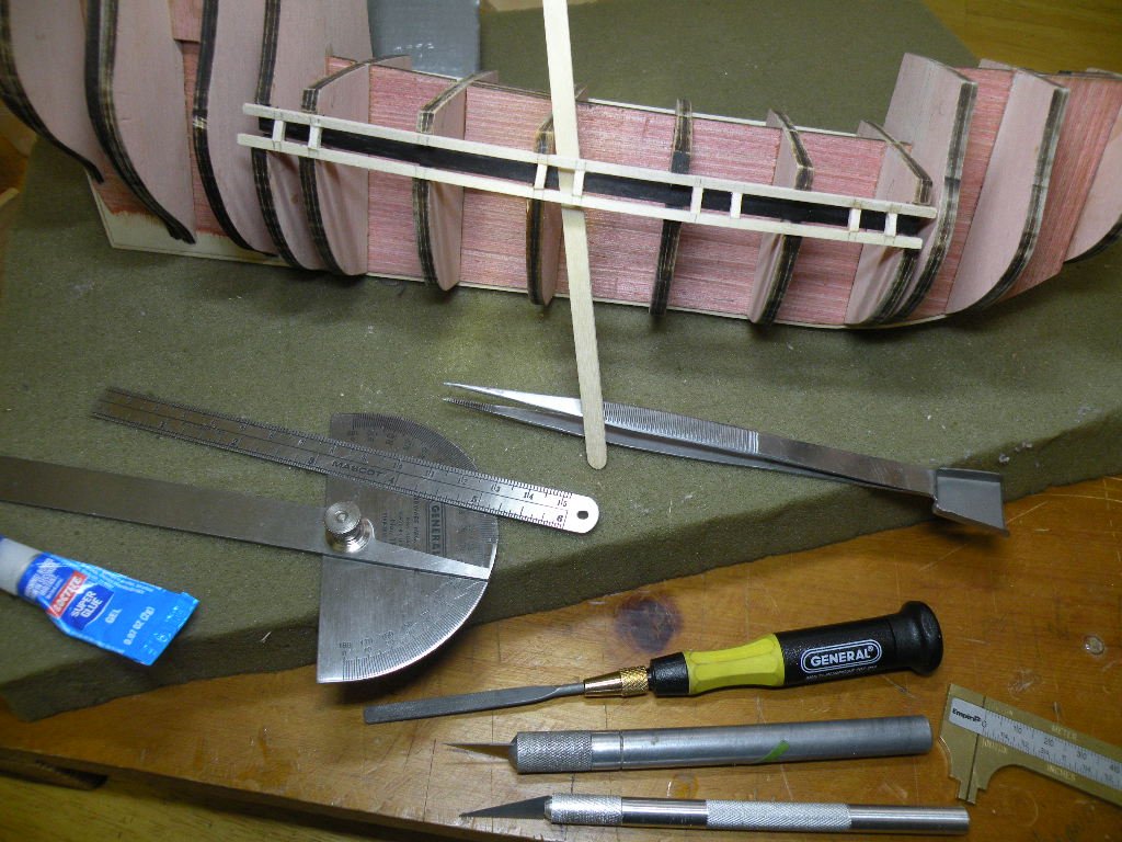
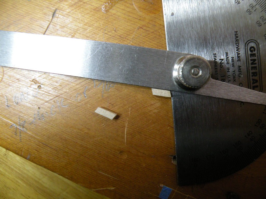
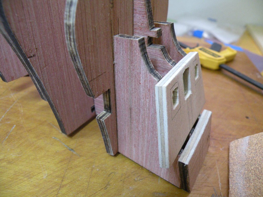
Gun Port Framing Well I surely didn't expect the complexity that this process has turned out to entail. I think I put in 8 hours today and got 8 of the 16 frames in. Going into it I thought it was simply a process of cutting these little 1/4 inch frames and gluing them in. Not hardly. Here's why: 1. The two strips between which the frames sit are not directly on top of one another. Because of the curvature of the hull the top frame sits a mm or so more inboard. Chuck's instructions note that the frames need to be cut at an angle (turns out to be 76 degrees) in order for the top and bottom to seat under and over the two frames. Interesting since I don't know of any miter box that will cut a 76 degree angle. 2. Unless you've put the two strips on super perfectly (which I didn't apparently), the gap between them can vary from the 1/4 inch that the frames are supposed to fill. In my case there were variations in the gap from less than half a mm to a bit over half a mm. More or less a 1/64th to a 1/32nd of an inch. This meant that each of the frames had to be measured, marked and cut individually to both length and the angle. 3. There is nothing backing the two strips, so when a frame is pushed into its place, I had to hold a swizzle stick behind it so as not to push it too far in. The framing will faired to the hull later, but I wanted these frames to sit flush to the strips. 4. If I could get the frame to have a nice snug fit I used CA to hold it there. It there was any wiggle to the frame I used carpenters glue. It would be hard to describe the process I finally developed for marking the 3/32 inch strip of wood at 76 degrees, cutting it, filing it, etc. Needless to say it was an interesting day. The pix tell a better story. I hope I've learned a few tricks (I must have cause the first frame took 4 hours and the last 7 only 4 more) that I'll apply tomorrow in doing the other side of the boat. The last photo shows where I got the 76 degree angle from.

-
LOL Richie... I had a feeling I wasn't using that word correctly.
-
Got started on the dummy cannon strips and the cannon port framing. Turned out to be surprisingly intricate work. Some of the little rebate notches to hold the upper and lower framing strips needed to be faired. Again, laser cuts only do 90 degrees and there is a definite curve to these strips. Not a lot of holding surface to these little notches either, and not a very good position to use strong clamps. So I decided to use CA glue on the first and last bulkhead as well as a dab of it on the middle one. The other 4 I marked and applied PVA to both the notch and the strip. This is one place where spot gluing is called for. Applied the PVA first, then when ready, dab on the CA gel and press the strip into place. Its nice to be working with a size model where my hand can span just about the whole work area, allowing me to apply pressure to the 3 CA spots. When the CA set up I added some clamps to the other 4 spots, though they were all sitting pretty snug in their notches. Came time for the last strip and it just wouldn't test fit well. It all looked pretty well faired but I couldn't get the strip to sit comfortably in all the bulkhead notches at the same time. I soaked and bent the strip onto a "jig" and in the morning I hope it'll sit better.
-
Richie my friend you're not the only one. I can stare at the model for hours trying to get things straight in my mind. Particularly when I'm going to bevel a part off the boat. I don't know how many times I bevel the wrong edge. I've taken to penciling onto the piece the area that needs to be taken off. Then of course its worse like you said when the boat is upside down -- but its alot easier to work on it in that position sometimes. So far on this build I have only applied glue to the wrong surface but once.
-
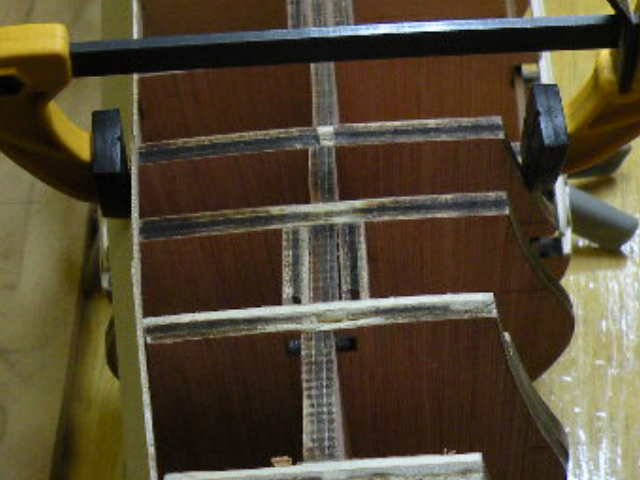
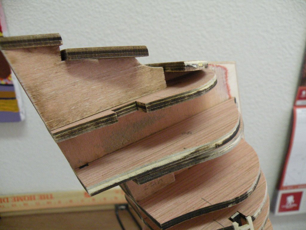
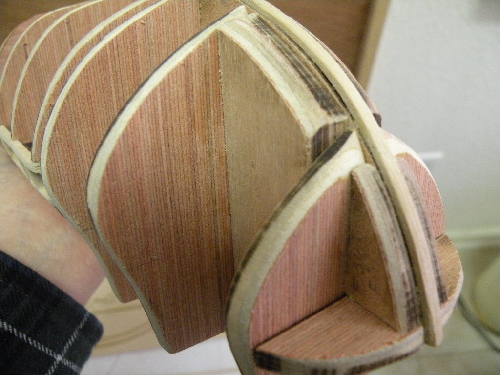
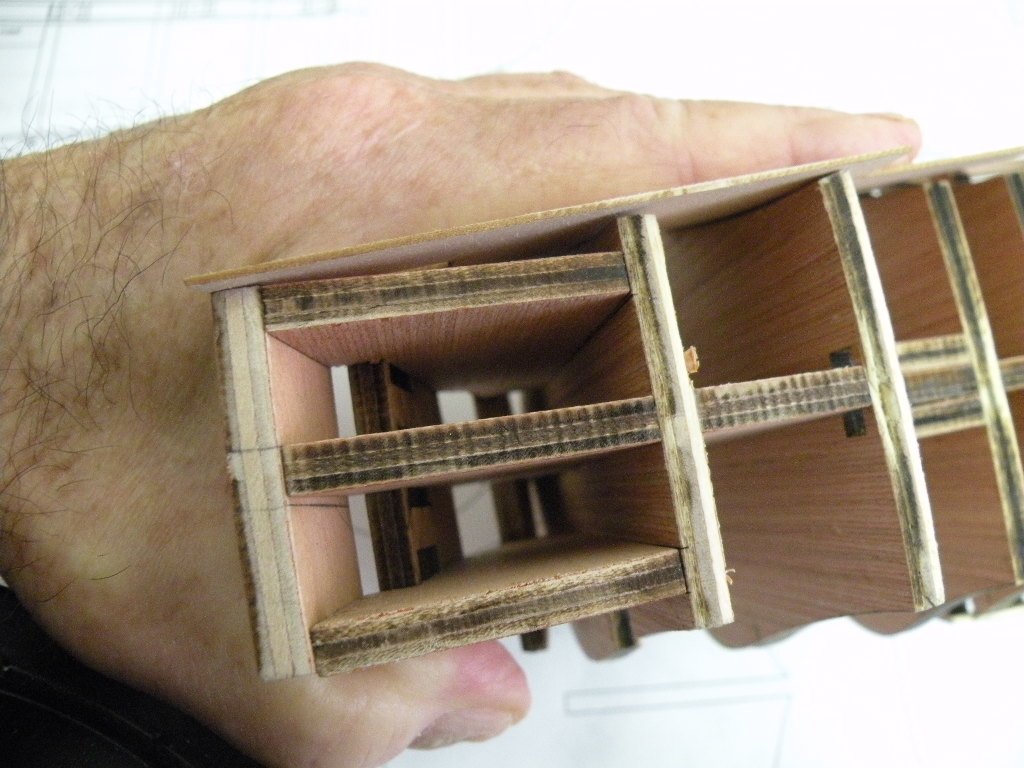
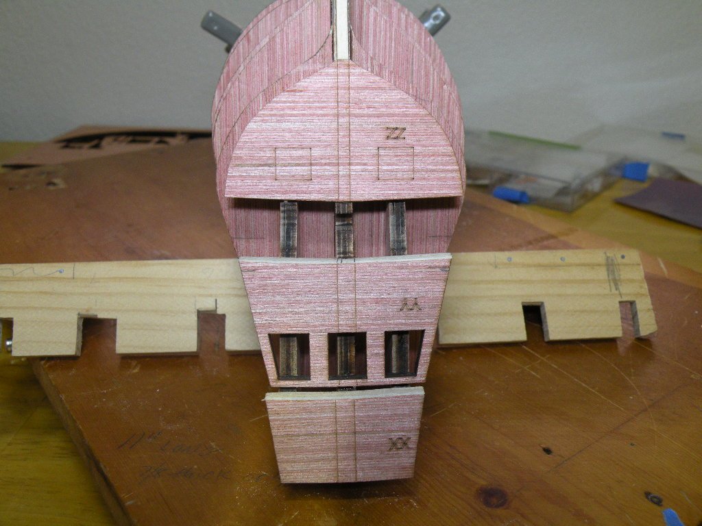
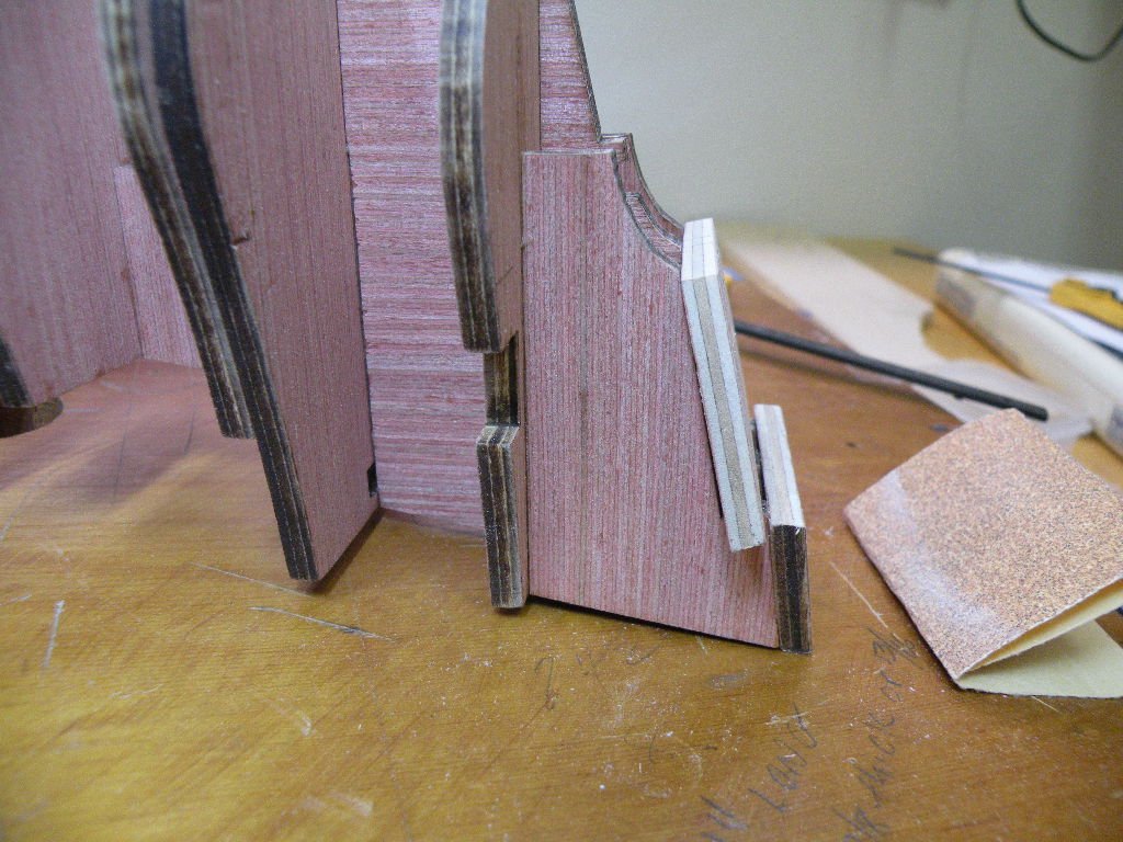
Stern pieces beveled and glued on. I think its a good idea to do the beveling (call it fairing) off the boat. Particularly for the YY piece which will be planked as part of the counter. It would be touch to get the right files into that space once the pieces are glued on. Pix below are upside down. You can see how the counter has to curve smoothly onto the YY piece so as to lay the planks down. The XX piece was beveled on its top edge to conform to the BF angle. The ZZ piece didn't get any beveling at this point but I think later its side edges will be faired to the hull. The ZZ piece was a bit tricky to glue on. Not much glue surface -- only the BF down the middle. The two outside stern frames do not extend down far enough to make contact with the surface of ZZ. ZZ sits on a bit of a notch in those frames and the BF. Actually, when right side up, ZZ sits on the tail end of the stern flush with the rabbet, and tucks under those notches in the stern frames and BF. So there is actually a triangular shape gap between this ZZ piece and bulkhead 5. Also note that the top edge of piece YY is camphored. I noticed that when I test fitted it to the frames that because of this camphor it could rock from side to side like a hobby horse. The frames are not adjusted to this situation. So when gluing it on, to be sure that I had it on squarely and not tilted a bit to one side or the other, I put a temporary shim on each of the outside notches (.6mm did the trick). As soon as the glue set enough I pulled these shims out, leaving a .6 mm gap between the top edge of YY and the notches in the frames. I worry not about these gaps. There is plenty of glue surface in other places. Trick I do when I'm applying glue is transfer the reference lines to the backside of the piece so I know where to apply glue. Remember: Pix below are upside down
-
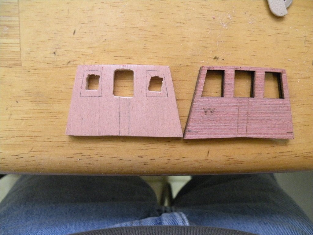
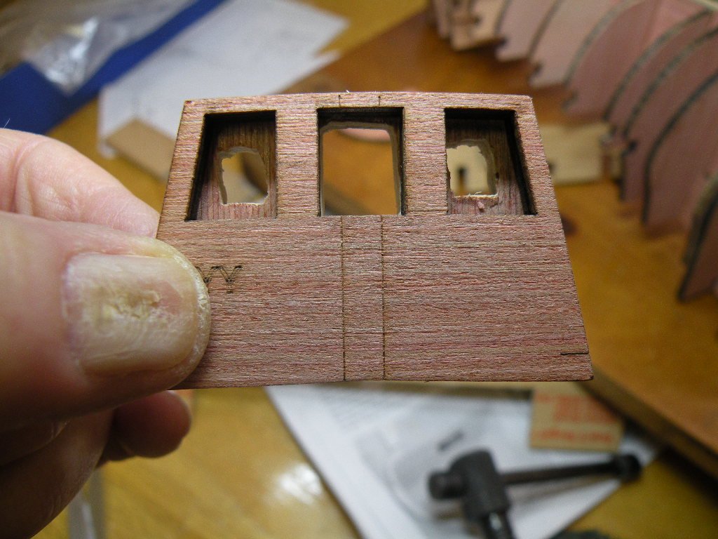
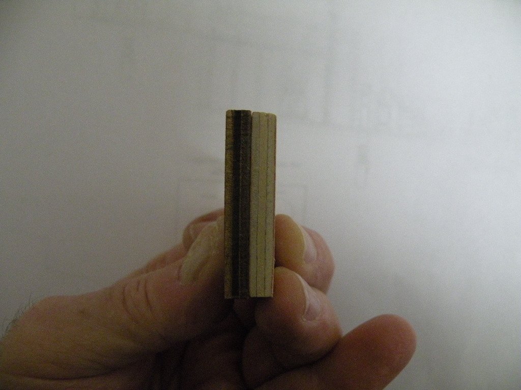
Good eye -- in part. I think the new part is ok except that in posing for a couple of those pix (the ones with the planking balanced on it) the piece was put on the model upside down. I'm looking at the pic of the pieces sandwiched together and the one of the two pieces side by side and those are pretty definitive that the new one is an exact replica of the old. I am opting to use the original piece anyway. I don't feel like finishing the job of filing out the windows today. More or less it was an exercise in proving to myself that if I should really screw up a part I can probably make a new one. So I'm going to glue on parts YY and ZZ this morning and hopefully (after chores are done and hair is cut) still have time today to put on the dummy cannon strip and the framing for the cannon ports.
-
Richie, I hear you regarding what might be the issue with this curve. I'm going to check it all from the perspective that my placement of the stern pieces might be off. But here's the thing -- even if I put the stern pieces on too high (or low looking at it upside down -- which I often find easier to see things), this YY transom piece sits on it (or under it when the boat is right side up) so those would move in tandem with the stern frames and the issue would still be the same. Also, I put those on where they would be flush to the BV so that the false deck would lie flat. All in all I think it comes down to my freaking out over having to bevel off a ton more wood than turned out to be the case. After all, it now appears that virtually all edge pieces need fairing and beveling to comply with the contour of other pieces. It comes down to the fact (as someone noted) that laser cuts have to be square.
-
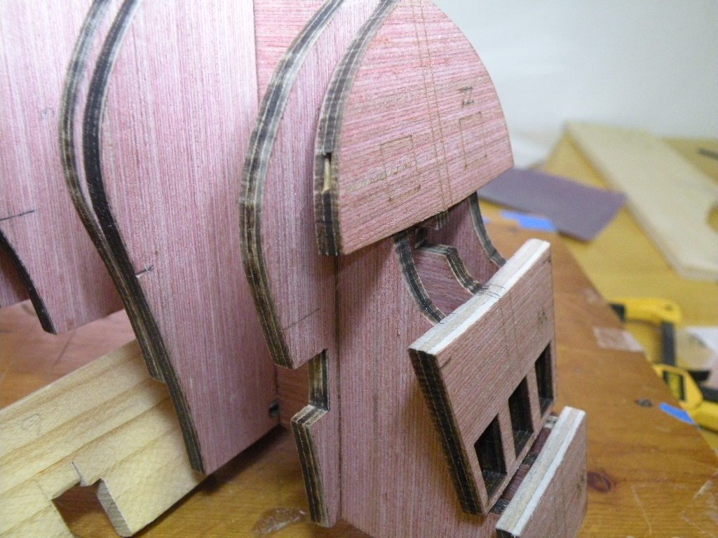
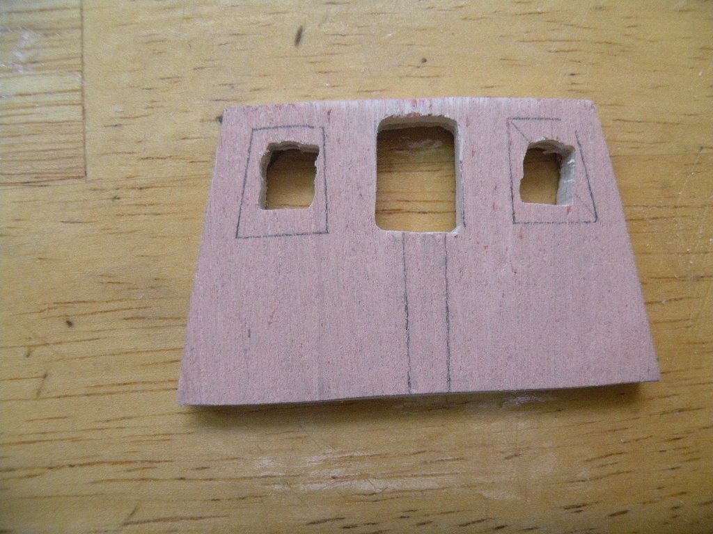
I believe I solved the problem of how to make the curve of the counter flow nicely into the YY stern piece. In the process I rekindled my interest in moving to scratch building. Problem I had was I didn't know how much wood to take off the YY piece in order to make a smooth curving planking surface. If it was going to be a lot of wood I preferred to do most of the work off the boat. So how to know? I decided to make myself a spare part out of the remains of the template plywood. Hint (probably everyone knows this) don't throw that stuff away -- it comes in very handy many times). So I cut the piece to shape on the Dremel scroll saw and "perfected" the edges with the disk sander. Placing the new experimental piece in place with the boat upside down it came clear that the curve could flatten out alot when it hit the stern piece; meaning a whole lot less wood to take off. I also realized I would be dealing with 1/8th x 1/16th inch planking here which is considerably smaller than the 1.5 x 5 mm planking I was used to using on my last build. Its interesting to find how much my thinking has to change having moved to a much smaller scale model. So I beveled this spare piece and and laid some of the planking over it. Yes. I think it works quite well. So well in fact that I started thinking about using my newly made piece in place of the kit piece. No reason really other than I could avoid doing the beveling over again. And, my hour's work would not have been in vain. But to do so I'd have to cut out the 3 windows. Decided to go for it. Drilled 1/4" holes (in three steps) in the center of the window spaces (copied from the real piece) and began filing into rectangles. I've finished just the middle window and that alone has taken 2 hours. So tomorrow I'll decide whether to bevel the kit's piece and use it, or continue to finish my spare piece. I'll probably do the kit's piece. The day's work was quite a lot of fun and like I said above, showed me that with patience I could probably do a credible job of scratch building a simple vessel.
-
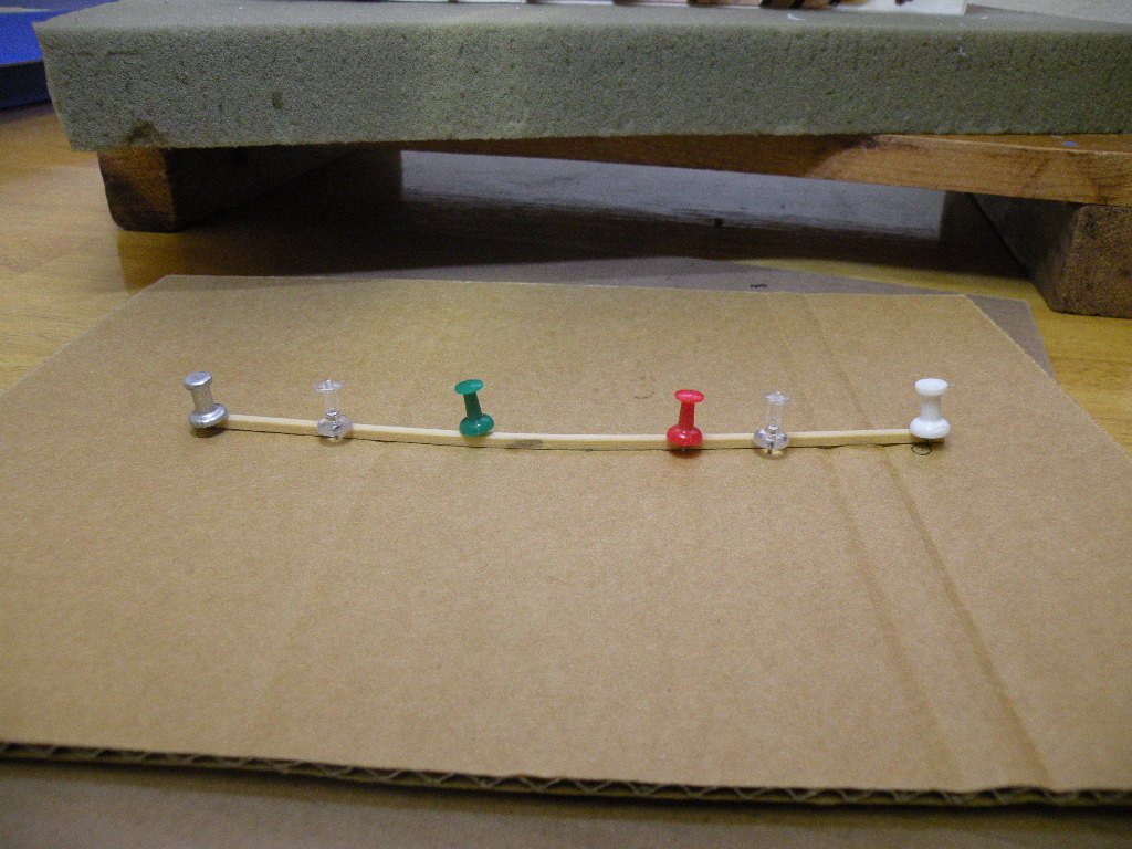
Richie, thanks for continuing to tune in and for your input. As for the hooks in the blocks -- I'm not worried about doing the model incorrectly. Like I said, if so it can be fixed easily when the time comes. God knows how many blocks were done incorrectly on Bounty and later given an extra twist. I'm just wondering if there is a standard way in real life (for one reason or another), that the hook would be stropped parallel or perp. to the sheaves. Maybe the answer is that in real life the hook would be lashed to the block through its own eye at the top of the hook, and not be part of the stropping wire as it is in modeling. That then would beg the question whether the eye of the hook is perp. to the half eye of the hook or are they parallel. Enough is enough I would say. I need to take a valium to stop thinking about this. Its minor.
-
Well maintaining a build log is more technologically challenging for me than model ship building. Just can't get the method down to insert pix where and when I want and to caption them. So the previous post contained several more photos than I intended. But all of them in there own way shows my dilemma -- how to shape the bottom edge of part YY to conform to the curve of the frames so they can be planked over? What tool to use? To do all or most or none of it off the boat? Does it really entail taking off as much wood as the pix show? Its not just photography exaggerating it -- it looks like a lot of wood cause it is a lot of wood. Am I conceptualizing the planking of the counter incorrectly? There are going to be several strips of very narrow wood (like 1/16th x 1/16th) put under there so I'm wondering if those will change the shape -- at least the shape that I'm seeing in my head which is a curve that continues through the profile of YY.
