Captain Al
-
Posts
613 -
Joined
-
Last visited
Content Type
Profiles
Forums
Gallery
Events
Everything posted by Captain Al
-
How to avoid twisted lanyards
Captain Al replied to Captain Al's topic in Masting, rigging and sails
You folks have been tremendously helpful. Thank you so much. The funny thing is that I've been aware of the inside to out, outside to in sequence but apparently just execute the process incorrectly. (I never made my free throws either). As for the final run and tie off, I had that totally wrong. Its clear that the lanyard isn't put through first thing when it comes up and is then tied off, but rather it is wrapped around and tied (of sorts -- looks like just a simple granny knot or single hitch under itself) and then the end is secured through the stropping gap. So its back to the bench for some more practice. -
Boyd is correct. The knightheads are on one of the laser cut sheets but are just hard to find. As far as I can tell the bowsprit inboard half is held by these two pieces and then further back held by a hole in another part (how's that for a precise description?). I put the bowsprit together but I've held off installing it for one big reason: its going to make your model another foot long and that means when you are doing a lot of other things still to come you'll be turning the model around a lot. You better either have a very large workbench or put some padding on the bowsprit tip. So my knightheads are tucked away as well in a little baggie. I would also suggest that you put the bowsprit on first and hold it in place somehow and then put the knightheads on. If you notice, they do not form a complete circle surround the bowsprit (at least mine don't). If you place them on the deck too close to each other the bowsprit won't fit through, and too far apart it will have a big gap. If you put them on around the sprit in place you can put them snug up against the dowel. Your problem is not as bad as the one I had which was that the inboard end didn't get into the hole straight on. That part, whatever it is, must have been put on just a degree askew. I had to file the hole larger on the port side. This may also help you. One of the first things I did before actually starting to build was to pop all laser cut parts out and put a pieces of blue painters tape on each one and put the part number on it. If there were multiples with the same part number I'd make sure I had them all and then wrap them in the tape and label them. All these laser cut parts then went into a zip lock bag numbered 1-100, 101-200 etc. It has made finding them when needed very easy. In 2 years of working with them I only lost one. And coincidentally I think it was one of the knightheads. Having the other one helped me make a duplicate from the scrap sheets. I never throw those away.
-
How to avoid twisted lanyards
Captain Al replied to Captain Al's topic in Masting, rigging and sails
Replying to both Mike, Beef and Stockholm....Mike, I think you're partially right in that if the lanyards were a bit stiffer they wouldn't spin as easily. I have some real seizing line which is waxed but I think its too big to use. So I might look to use the Vice Admiral's beeswax. Beef, its funny that I had that same thought in mind when I was building the channels. If the lowers are fixed, how could it twist? What I found though was that the twist just started above the deadeye. I guess I could be convinced either way, but for the moment I've freed them up and its working a lot better than it did when they were stationery. But then along comes Stockholm to confirm your way as the real way. What I might then do is reeve the lanyards, hold them in place untwisted, then drop a wee bit of a drop of CA into the slot where the lower deadeye sits. Stockholm --- I had to laugh when you quoted that old saying cause first of all its absolutely true. My laugh came in cause I tend to remember things with little sayings like this (e.g. to tie a reef knot I'm always saying to myself "over and under; under and over" even after probably tying this knot 1000 times). So when I found this to be truly a good part of my problem, and I wanted to remember to do it, I made up almost the same saying. I guess I think like an old salt. But the sheer pole thing is intriguing cause I believe the AL plans show such thing. I didn't know the purpose for this. I thought it was just a solid first step up to the ratlines. It doesn't have much effect though when you're still rigging just the first or second shroud. Thanks all for the time and interest. Here's a couple of pics to show what progress I've made. One side (forgot which) still has a half twist, the other doesn't. I'm not pleased with the tension on the shroud but maybe its OK. And maybe I'll get better as I go along.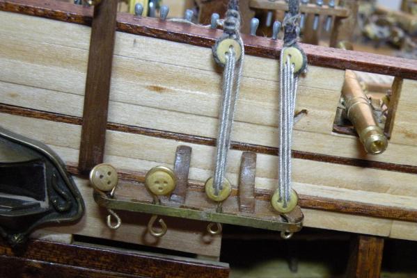


-
How to avoid twisted lanyards
Captain Al replied to Captain Al's topic in Masting, rigging and sails
I believe I am druxey. I'm following the diagram in Peterson's rigging book. But then again, I could be doing it perfectly; just backward. I will give that a closer look. If you picture the two deadeyes as facing you (like little smiley faces) and you are looking at their outboard face, I have the triangle of holes opposite each other -- the upper deadeye's top hole being up and the channel deadeye's being at the bottom. So there is the maximum distance between these holes. And the other two holes then line up straight up and down to their counterpart hole on the other channel. Looking at it this way, I've started with a stopper knot on the inside of the upper deadeye's left hand hole, run the lanyard through it and through the lower deadeye's left hand hole from inside to out. Then I've strung to the outside of the upper deadeye's center hole, back down to the lower center hole (coming in from the inside and out on the outside), then back up to the upper right hand hole (outside to in) and finally back to the lower right coming from inside to outside. The rest of the lanyard is then strung back up and threaded through the stropping of the top deadeye, wrapped around the shroud two or three times and tied off. Like I said, I'm following Peterson's diagram but maybe its the inside outside sequence or the left to right sequence that is causing the twist cause maybe that's not in opposition to the lay of the shroud. Or, as I've just realized while writing this, perhaps it comes down to which side of the boat you're looking at (or rigging). What I've described here was facing the starboard side, with forward being on my right hand and aft being to the left. So if I start by stringing the left hand holes first and finish with the right hand holes, I'm stringing aft most first and working the lanyard forward. But if I do the same thing on port side, still starting with the left hand holes and finishing to my right, then I'm really stringing the lanyards different from the starboard side -- on port side this would mean I'm starting with the forward most holes and ending with the aft most holes. Since the shroud's lay is the same whether port or starboard, this could mean something. Or maybe it means nothing? BTW, we talk a lot of the 'lay' of the rope (or thread) and I know its either right hand or left hand lay. But how do you tell one from the other? If you look at the rope it has lay lines running from the upper right to the lower left. Is this right hand or left hand lay? If you twist this same rope counter clockwise, it will open the strands. If you twist it clockwise it tightens it. Does this mean its right or left hand lay. Is the vast majority of rope and thread now right hand lay? -
How to avoid twisted lanyards
Captain Al replied to Captain Al's topic in Masting, rigging and sails
Second that Jud. Thanks for the quick study. I've redone the channel deadeyes to not only allow them to swivel but to put the deadeye holes in a more proper sequence (they were OK but not perfect). I also closely inspected the deadeyes that I was using and found a few that were really bad; hardly any space at all between the holes. I'm going to substitute the deadeyes that just arrived from Model Expo and look 100% better. Also going to stretch the thread a bit and do everything else suggested. So thanks to everyone who've contributed their thoughts. Yes, only msw affords this kind of support. -
How to avoid twisted lanyards
Captain Al replied to Captain Al's topic in Masting, rigging and sails
BH, that sounds very clever. So what you're saying is that if a single lanyard causes the line to twist once, then six falls of the lanyard would twist it six times. So you reverse twist the shroud six rotations (could actually be six half rotations but that's yet to be determined on mine) and secure it temporarily in that position while you thread and tension the deadeyes. When that's done you release whatever is holding the shroud and voila -- it spins back to a good lie. Going to try that. Thanks. -
How to avoid twisted lanyards
Captain Al replied to Captain Al's topic in Masting, rigging and sails
I suppose its cotton. The kit's parts list says it is. The shrouds are made with .5mm cotton thread. Is there some way to take the stretch out of it before using it? Maybe hang it with weights for a day or so? Hang it wet? Maybe a very light coat of watered down pva? -
How to avoid twisted lanyards
Captain Al replied to Captain Al's topic in Masting, rigging and sails
Well that's an interesting question because the lower deadeyes were secured when I started. I had glued them into the channel slots so they would stay put while I glued on the cover to hold them. After the twisting started I couldn't think of other reasons or cures so I broke the deadeyes and chains free to swivel. This didn't fix the problem. If both deadeyes were fixed I think it would be OK. But you can't fix the deadeye on the shroud. Maybe the shroud has to be prevented from twisting until the ratlines are tied on. Maybe that holds them from spinning. Does it make any sense that maybe the shrouds have been looped over the mast head upside down? What I mean is that maybe if the lay of the tread was opposite to the tension being put on the deadeye it would hold it in position. -
I'm having a heck of a time getting the lanyards between the deadeyes of shrouds from not twisting up. They seem to want to go with the lay of the thread of the shroud above them. I'm ok until I put the least bit of tension on the lanyards. When I do, they spin around. What are the possible causes of this and cures? The deadeyes are starting out parallel to each other, and the lower ones (in the channel) are free to swivel. Could it be that I just need to hold the shroud in place as I string the deadeyes? It seems like this would just delay the twisting until I was done with the deadeyes and then whammo, it would twist up into the solid mass of 6 strands again.
-
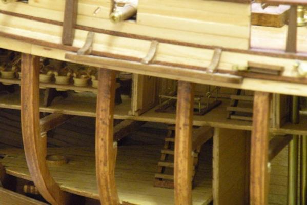
Several of us builders are using the Artesiana Latina kit. There are instructions and materials provided to make simulated cotton bales. I've seen a few completed models that have used these bales in the hold (note the model is open on starboard side) and which look pretty good. Aside from the scale dimensions the kit suggests (my guess -- way too large), my real question is whether or not and why the Bounty would be carrying cotton bales. McKay's book makes no mention of the ship's cargo. Does anyone have any knowledge of this? The space it takes up could be put to more authentic use.
-
LOL Bryan. That 3rd cross tree (or lack thereof) cost me about 2 weeks and a lot of head scratching. Once you find that little spreader piece in the parts list or on the plans it all comes very clear. Another part of interest will be the 'cheeks.' It seems A.L. wants you to put on two layers -- one being the inner layer called the 'cheek stiffener' and the other being the cheeks themselves. After fiddling around with the two pieces and trying to make them look like the plans show them (with the inner one protruding out beyond the profile of the outer one) I decided to forego the inner one. I just filed the port and starboard sides of the mast flat and put the cheeks on. Here's a tip for what its worth.....because you'll be angling the platform supporting trees about 6 or 7 degrees, its easier to glue them on before putting the cheeks under them. That way you can just angle the cheeks to sit flush underneath the trees. If you put the cheeks on first you'll need to be sure that two independent pieces (each cheek) is set exactly at the same height on the mast and at exactly the same angle. I just thought that was tougher to do than the other way around.
-
VandaLay Hold it Plus
Captain Al replied to Nirvana's topic in Modeling tools and Workshop Equipment
I too join in with an apology. Very sorry. I have a tendency to turn any subject into a topic of mirth if and when possible. I did appreciate the review and as a matter of fact intend to research some of their products. I should have first shown my appreciation before joining in the merriment. So thank you for taking the time. Now, having said that, are you now or have you ever been a member of the Seinfeld fanatical society? Those of us who are simply can't resist bits like this.- 19 replies
-
- 1
-

-
- VandaLay
- Industries
- (and 6 more)
-
Your looking great Bryan. I'm quite impressed with your creativity. That's where the fun lies. Did you just put some black paint on your 1/2 pounders and the pump handles? I left all my brass as shiny as could be and now kind of wish I had taken the time to darken certain parts up. But of course from the start my sole objective has been to put this thing together and make it look like a ship. I notice (it may only be the angle of photography) that you put the holes for deadeye chains in the exact center of the channels. I did the same following the plans to the letter. I then found that being so far inboard the shrouds were probably going to rub against the rails. So I have filled these holes (with the tips of toothpicks) and sawn and filed grooves into the edges of the channels into which the narrowest part of the chain linkage will fit. Then I'm covering up the slots with a strip of 2mm brass. I would have used wood strip but its easier to curve the brass and I'd already curved the corners of the channels (as perhaps you have). I don't know if I've updated my log to show some pix of these changes. If not, I will soon. Feel free to ask about the construction of the masts as I've worked through and around the A.L. plans in conjunction with Peterson's book on rigging and McKays Anatomy book. In conjunction with my buddy Boyd (thomaslambo) and a lot of help from Danny V., I think we've got the idea down pretty well now.
-
VandaLay Hold it Plus
Captain Al replied to Nirvana's topic in Modeling tools and Workshop Equipment
They're real and they're spectacular. -
I just got done figuring this out for my own build. The conclusion I drew using McKay and the A.L. plans is that the mizzen was raked about 6 or 7 degrees aft and the main and fore masts were perpendicular. If you are building this ship and you get to building the mizzen at this angle, remember to offset the trestle and cross trees the same angle so that the platform (crows nest) sits level after the mast has been stepped.
-
Anyone Use A Pin Nailer?
Captain Al replied to Julie Mo's topic in Modeling tools and Workshop Equipment
3/8" nails are pretty darn big for models. That's like 9 or 10 mm. The nails I have (came in my kit) are like .5 mm at most. -
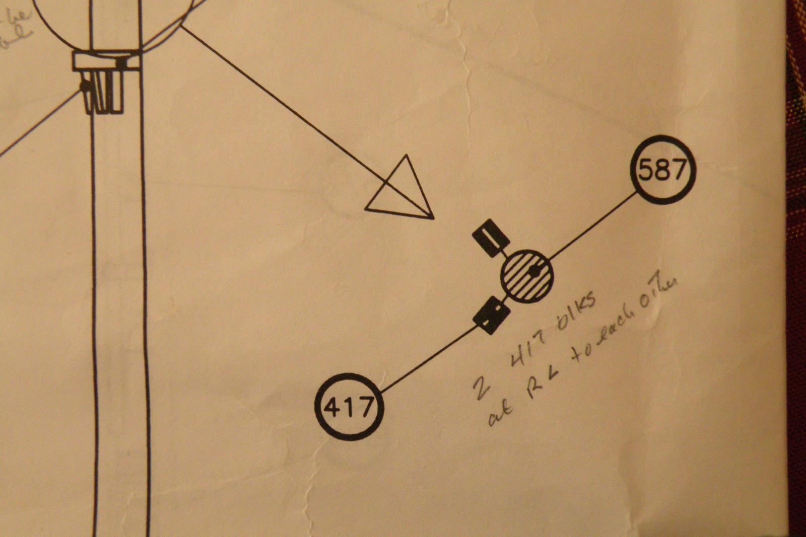
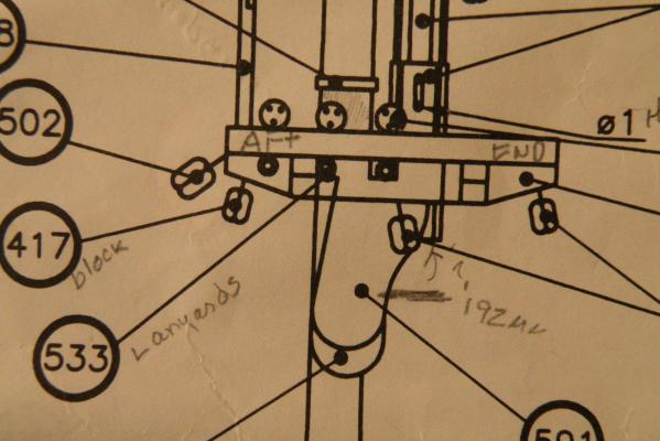
Thank you both CP and Danny. I should have learned long ago not to trust a schematic drawing from Spain to be accurate to the nth degree. Danny, of course your method with its collar and stiffeners not only looks better and is more real, but it is actually easier to build I would think. Giving A.L. the benefit, its just my inexperience that led me to the conclusion that what I was seeing in the drawing was actually how they'd seize it. The little line coming from the wooldings is perhaps just their labeling line. But, it could have been placed below the wooldings, couldn't it? CP, all roads seem to lead to 417 being a double. And I'm going to put it on even though I think its part of the running rigging which I want to shortcut wherever possible as I'm not going to raise sails. I believe this block is for the gaff sail halyard. Having studied the A.L. drawing for how that line is rove, I'm pretty convinced A.L. has made another boo boo in the arrows they use to indicate direction. Oh well.
-
OK, LA I'm here to lend whatever knowledge of bowsprits I can. First recall that I've posted as many questions about this than anything else. It remains a mystery. I put the wrong blocks on because the kit just doesn't describe each one very clearly. On the top of the bowsprit they should be hearts, not regular blocks and these will lash to another set of hearts coming down from the foremast on the stay and preventer stay. As for the tip and the sheaves etc. You need to drill a 1mm hole at that point and then with a file get it to be (I think) 4mm long...like a racetrack looks. I drilled two holes spaced appropriately apart and took out the inside (the back and home stretch so to speak) with a file. Make sure you align this hole at 0 degrees north (ie pointing straight up). I goofed it up one way or the other and Danny warned me that it will make a big difference come rigging. I would suggest you drill this hole before doing anything, and then orient everything else in relation to it. Its easier to place the cradle and other pieces (blocks and cleats) with the hole as a reference. I'm pretty sure where I went wrong is that I had to make an adjustment to the inboard end so that it would slide into the hole (forgot the part name). This probably threw my sheave hole out of alignment. Once you have the hole drilled and reamed to size (the size is dictated by the size of the sheave to put in it), you'll need to drill a small hole (very small) to take the sheave shaft. Try the best you can to make this hole 90 degrees to the fore and aft line of the sprit. I've taken to using my big drill press rather than trusting to do it free hand with a Dremel. Then put the sheave into the slot and insert whatever shaft you've made to hold it. I use a drop of CA on both sides which seeps into the shaft hole and holds it in. Hopefully the CA doesn't seep too far in and seize the sheave, but if it does, no big deal; this is only a model, it doesn't need to spin. As for the hooks and stuff there. It took a lot of looking at pictures and some other member's comments to get me to see the light. There will be a brass collar around the sprit which is seized somehow to the jib sail. The line that will run through that sheave we just built will hook onto the collar. This will allow the clew of the sail (I may have the term wrong, but the forward most corner) to slide forward and back a few inches on the sprit. In reality its a way for the crew to tighten up the shape of the sail. I haven't done the fittings to make this work yet. Have you figured out the 'bees of bowsprit' yet? If you need help in this let me know with a private message. Hope this helps.
-
LADon, lets go to your log and I'll try my best to answer some of your questions. But as you probably read above, I'm going to redo much of what I've done on this bowsprit. Too bad, huh?
-
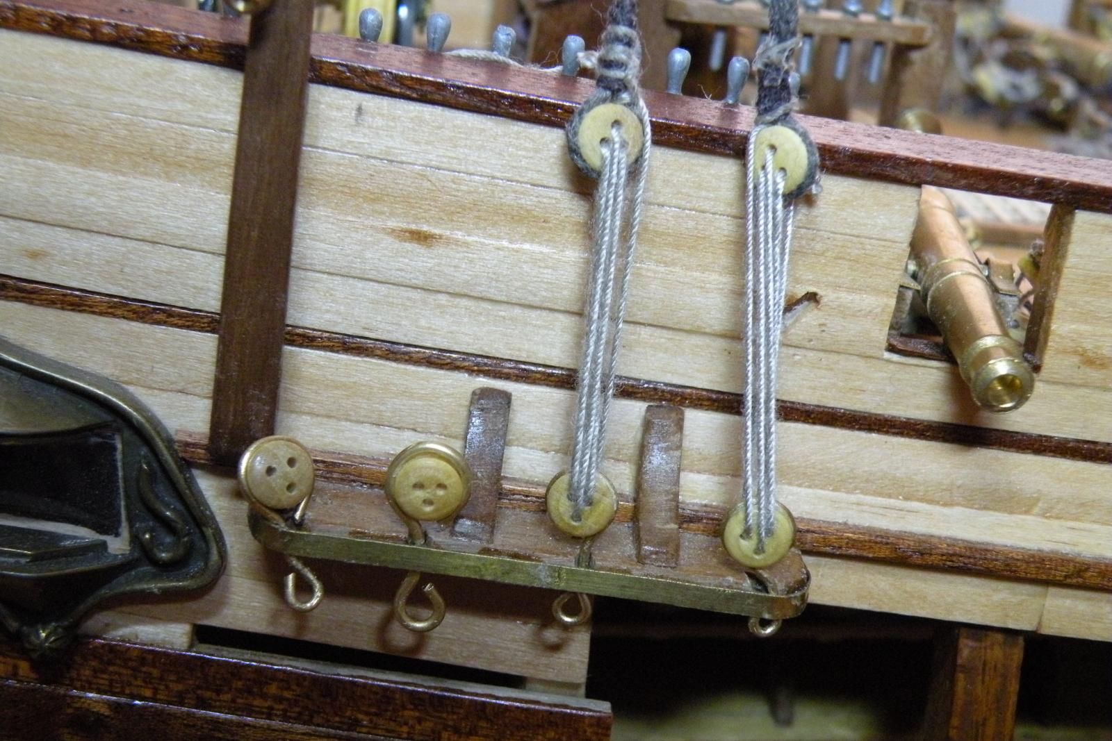
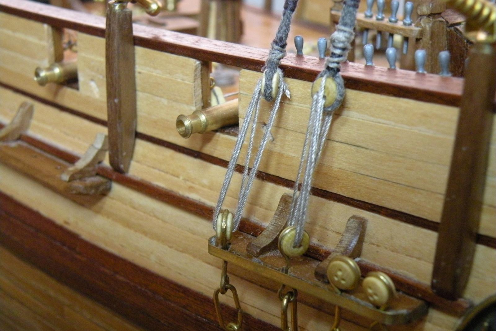
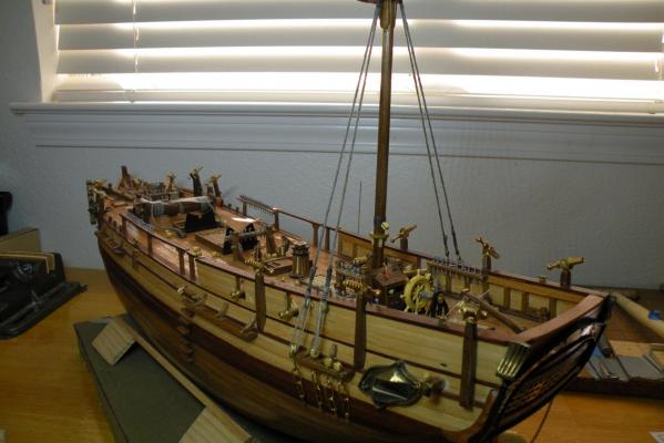
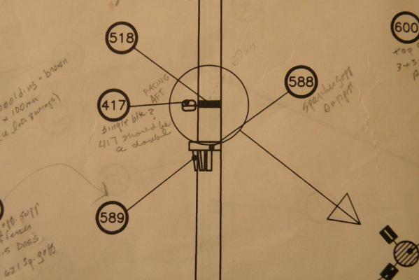
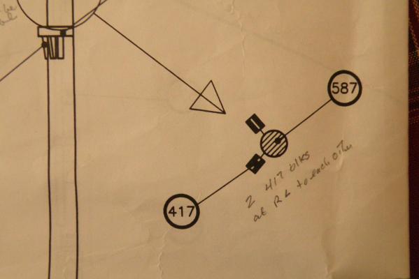
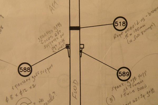
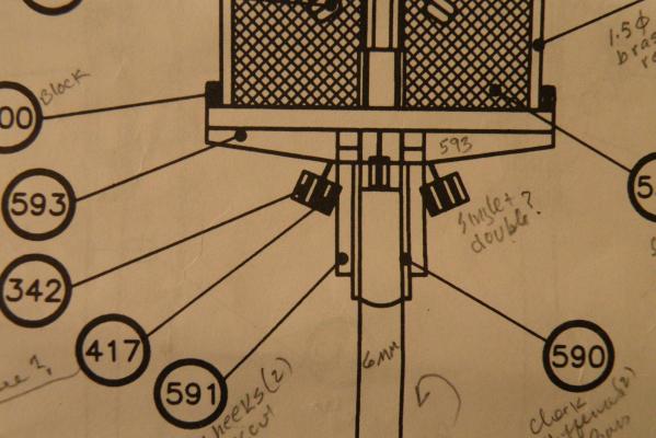
The last thing I need to add to the lower mizzen before I'll put it on the boat is the lower woolding with a block (or two?) seized to the mast by the wooldings. I think this is what I'm seeing in my drawings, but this is one area (reading drawings) that is certainly not my area of expertise. So I'm going to post some pix of the A.L. drawings of this area and hope anyone can help me answer these questions: 1. How are the blocks seized to the mast? It looks like the beckets are part of the wooldings. My thought is to strop the block leaving several inches of thread on both sides of the knot, and then wrapping those around the mast as the wooldings. Is there a better way? 2. I've been trying to determine for weeks if a 417 is a single block or a double. A.L. calls it a "block." Not much help there. The drawings are ambiguous to me. Up by the platform they clearly look like doubles sitting next to 342 single blocks. But down below they look like singles. That's how they appear throughout other drawings. No consistency. 3. Whether the 417 is single or double, are there two of them seized at right angles to one another or just the one? In the frontal view I see none (because of the view point), but in the side views there's also just one. EXCEPT when you look at the little blowup top view. Here it looks like there are two at right angles. What gives? Thanks any and all who can help me on this.
-
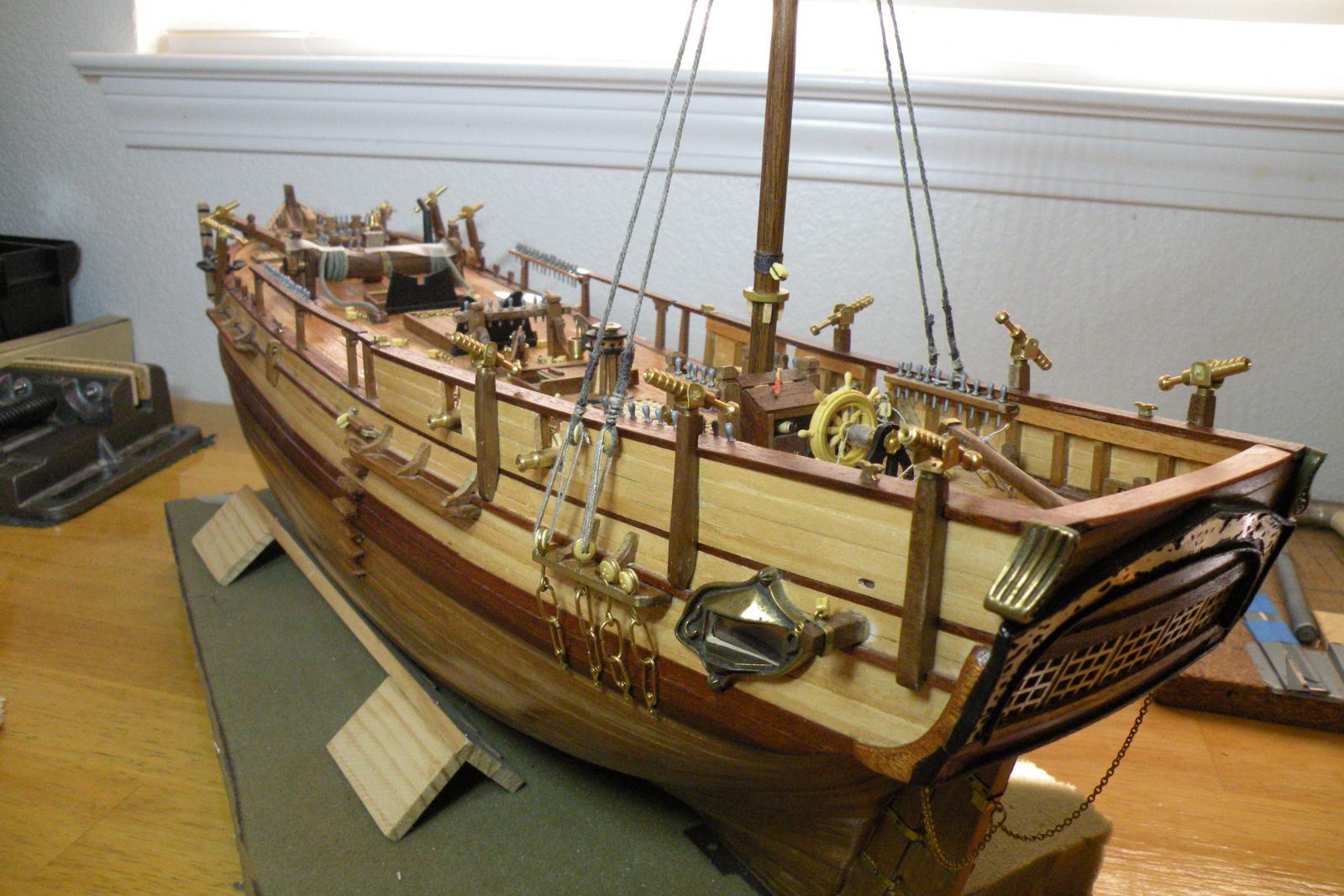
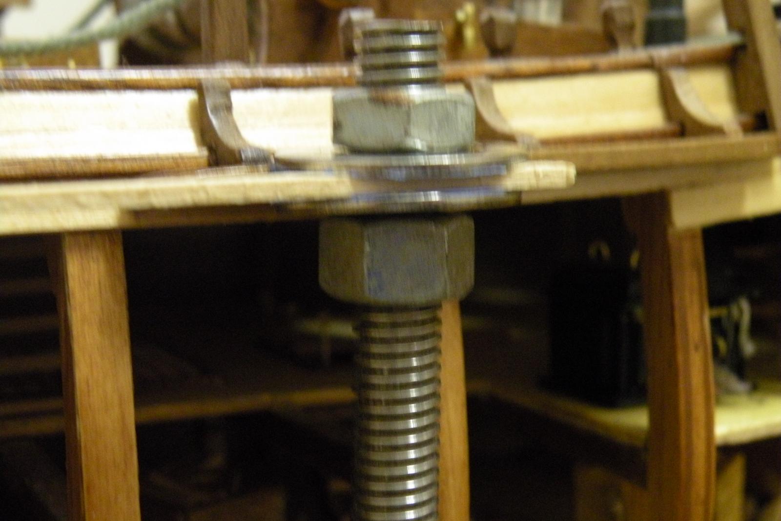
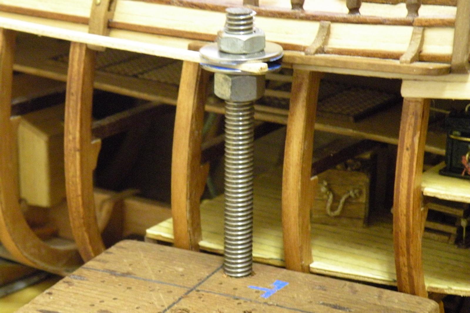
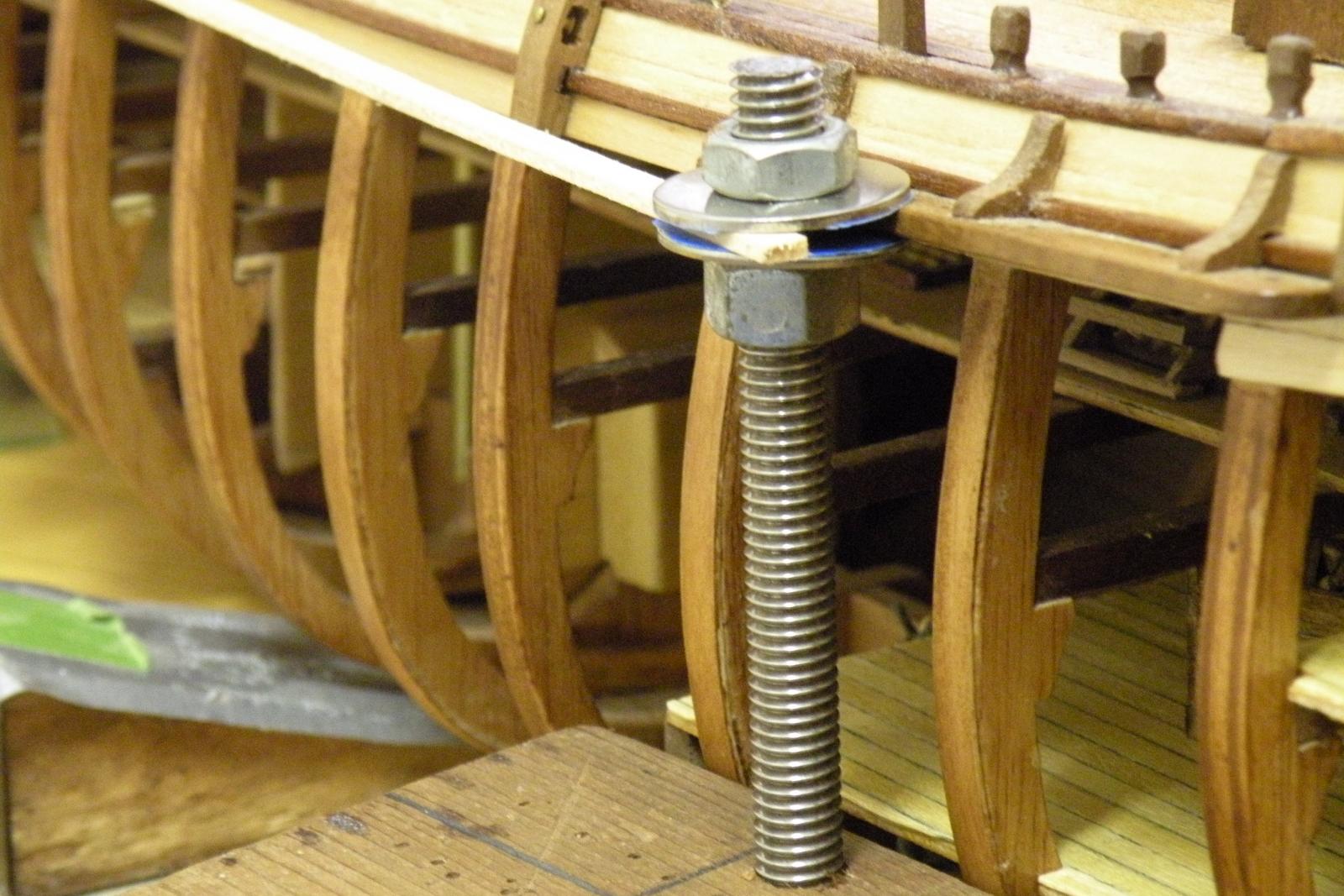
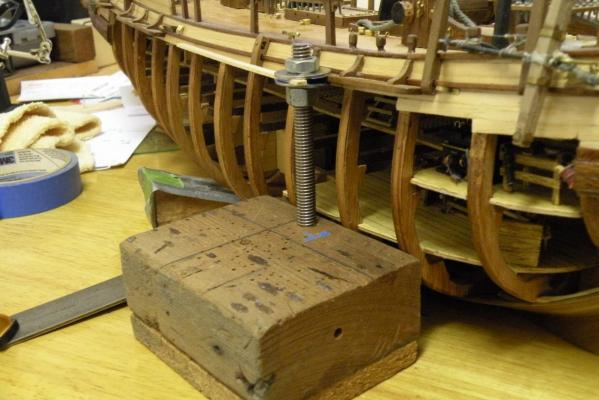
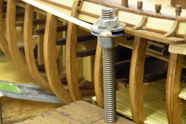
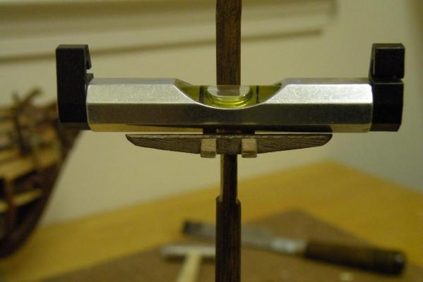
Thinking forward a bit I realize I probably need to change course and work on getting my channels in order and make up some deadeye chain arrangement. There isn't much more to put on this mizzen lower mast before I fit it to the boat, and I'll need to do that so I can loop the shrouds over them and put the chains in the proper angle. So I'll set aside the mast until I have the chains made up and the channel fixed. Recall that I already drilled holes in the channels for the deadeye chain plates. But having drilled them too far inboard, I'm faced with either filling and redrilling holes, or filling the holes and cutting slots in the channel edges to slip the chain into. I've decided to do the slots as I don't like the size of the holes that would be needed to insert the chains that I want to make. Besides, slots are more authentic. They'll be covered with a closure strip of 1.5mm x 5. The process of cutting these slots is pretty straightforward other than lining them up with the angle the shrouds will take up to the mast head. I'll get that angle and then use a razor saw to cut the opening (maybe have to sand or file them a bit wider than the saw blade kerf, but I don't know that yet). I've been worried about knocking the channels off as I sawed the slots, so I've rigged up a bit of a bracing system to hold the channels rigid while I make the cuts. Much better I think than my fingers. See pix below.


- 265 replies
-
- 2
-
-
- finished
- artesania latina
- (and 1 more)
-
Going forward small steps at a time I put the bolsters (A.L. calls them chocks) and cheeks on this morning. Nothing to brag about except to say at least I didn't forget them.

-
Are you saying that a seamstress does not walk into a shop and ask for thread or yarn of a certain diameter (as we would like to do)? Since we're on the subject, Danny has suggested using Guttermann quilting yarn for certain applications. While its easy to find, it doesn't seem to come in sizes. I've only seen it offered as 40 weight. My question then, is there a table or reference to translate a threads 'weight' into mm? For now, I trust in Dan's usage -- for the applications he uses it, if its one size only, then I'll use it only for that application. But I haven't factored in the model's scale. It wouldn't seem right to use the same thread size on a 48:1 model as on a 100:1.
-
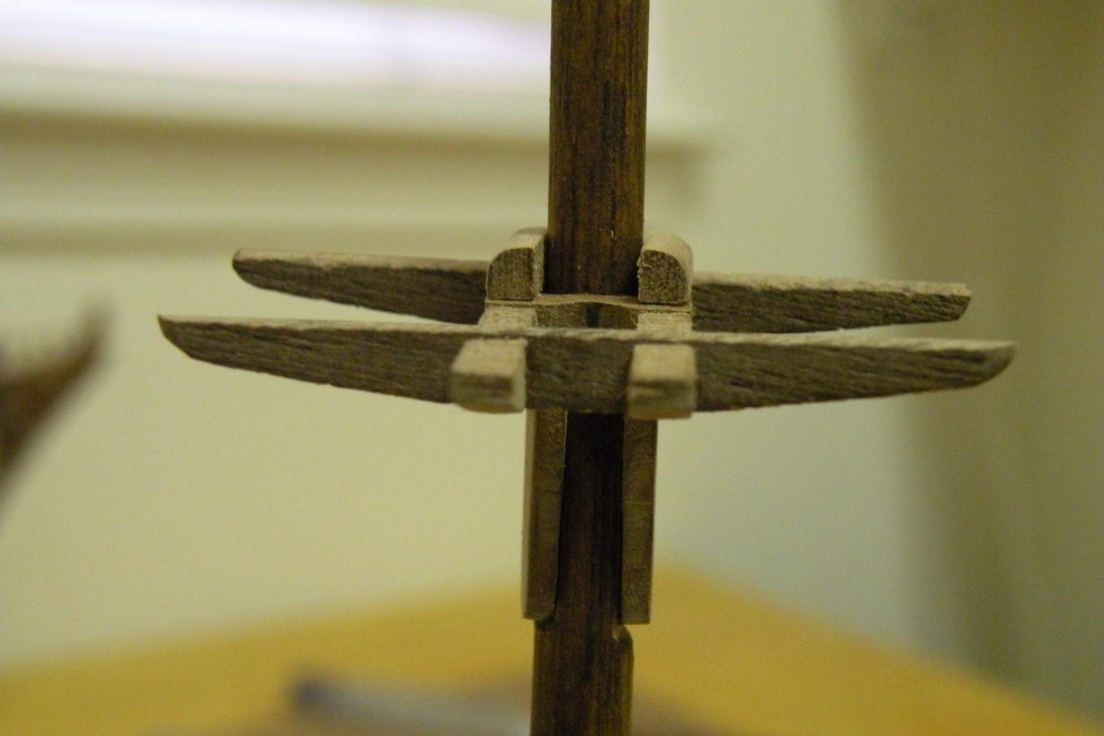
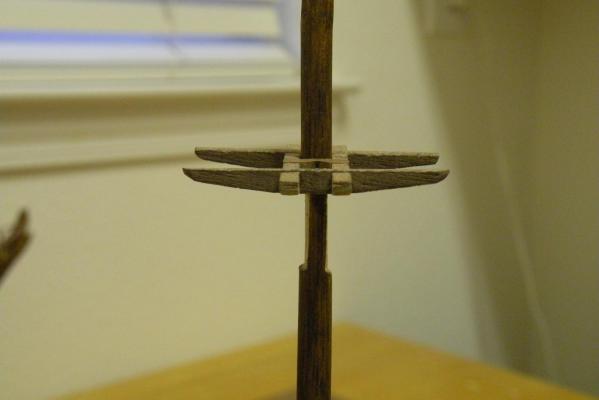
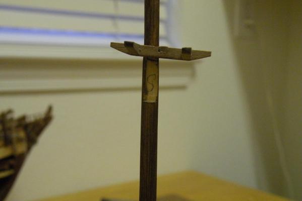
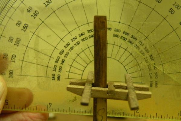
Sunday afternoons are as good a time as any for a quick update to the log. Before that though I want to give a big thank you to Danny V. I think we all realize and appreciate what an extraordinary resource we all have in Danny. I've been into many different endeavors in my time but I've never been blessed with someone so generous with their time, understanding of the pitfalls and frustrations that beginners have, and willing to share what is an incredible store of knowledge and know how. Danny's been advising me the past couple weeks as I pondered (almost to death) the intricacies of mast building and its relation to the rigging, and without his help I know I'd have abandoned my beloved Bounty and started building a pirogue. My last post was about whether to make the mizzen top mast 192 mm as the A.L. instructions said or 185 as the A.L. drawings showed. I didn't get much feedback from anyone (but my fellow Bounty builder Boyd -- I like the alliteration) so with his concurrence I cut off the bottom 7 mm. Lesson learned here was to trust in my own ability to read plans and figure out when A.L. had made a mistake (which they tend to do). So with that issue out of the way, I am moving forward with building the structure of the mizzen mast. I'd already put a few of the detail parts together -- the trestle and cross trees were fitted together and things like the spreader, bolsters, cheeks, and some of the stiffeners were ready. I put on the spanker gaff support and its stiffeners yesterday.The platform was built as was the stanchions and railing. Drilled the holes in the platform coaming for the stanchions. Lots of little things. Still lots of things to do. But I just wanted to get on with it, so this afternoon I took the plunge and glued the trees to the mast. I knew this was a critical process of orienting things correctly. I've already misaligned a sheave hole in the bowsprit and I didn't want to do that again. Alignment, I sense, is critical in 3 dimensions here. So I did my best using different devices to mortise for the cheeks as straight as I could (forward and aft), and be ready to put the trees on with the same orientation. I was undecided whether to put the cheeks on first, then lay the trees over them, or do my best to set the trees on correctly and then put the cheeks snugly under them. I opted for the trees first for this reason: it seems much easier to get the proper rake to the trees than to these little thin cheeks which were going to sit in the mortises and would have to be perfectly parallel to each other or the trees would sit cockeyed. These pictures show what I'm talking about. The trees needed to sit with a 6 degree tilt forward so when the mast itself is installed with its 6 degree rake aft, the platform would sit level to the water. Lots more to do but its a start on something that's really been hanging me up. So I feel pretty good. Forgot to note that the mast itself is held in a vise and made perpendicular with squares, T's and levels. Everything I could find except a plumb bob.
- 265 replies
-
- 3
-
-
- finished
- artesania latina
- (and 1 more)
-
Mike, I just found this post and log because you used Colin Archer in the post title. First off, its a beautiful and exquisitely crafted model so far and promises to be a real show piece. I'll be following it closely. Reason for my particular interest is that I used to sail two different double enders (Baba 30 designed by Robert Perry and a Pacific Seacraft 25 designed by Henry Mohrschladt) and your build comes as close to those designs as I've yet to see on a log. I've been contemplating trying to build one or both of my former vessels from scratch and maybe with modifications I can get the structural part done by following some of your steps. Deck plan and rigging I suppose would be from my own pictures. Thanks for sharing your work with us. Its always exciting to see someone's work that fits in with what I'm doing or thinking.