Jond
-
Posts
874 -
Joined
-
Last visited
Content Type
Profiles
Forums
Gallery
Events
Everything posted by Jond
-
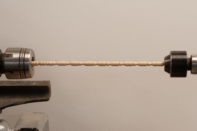
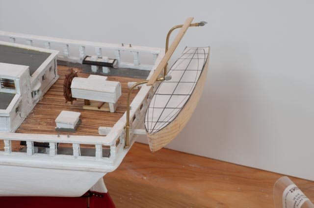
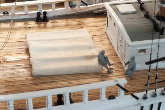
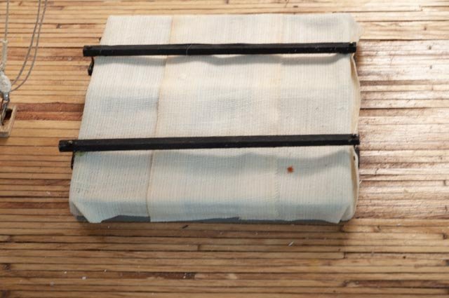
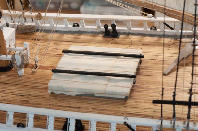
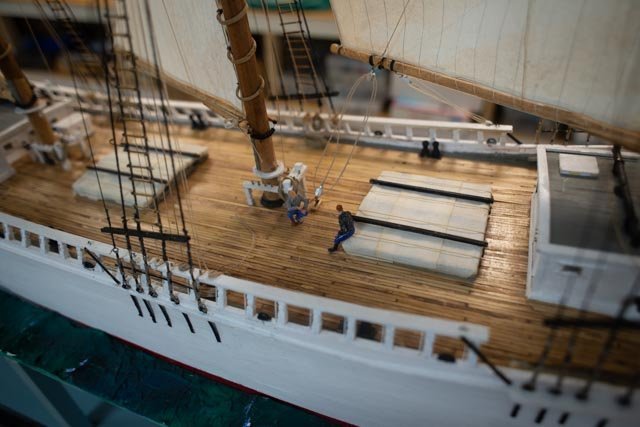
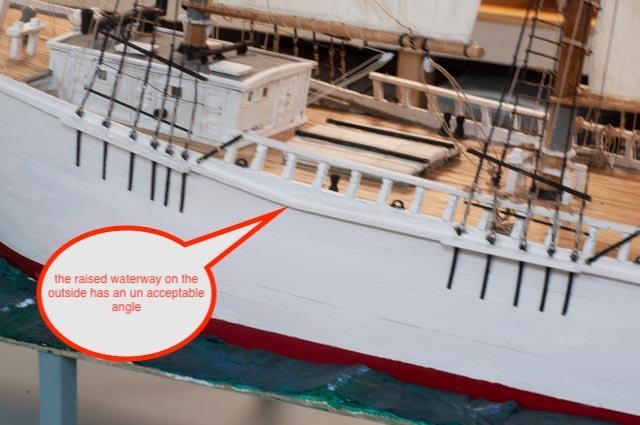
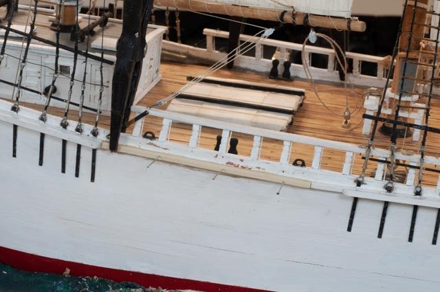
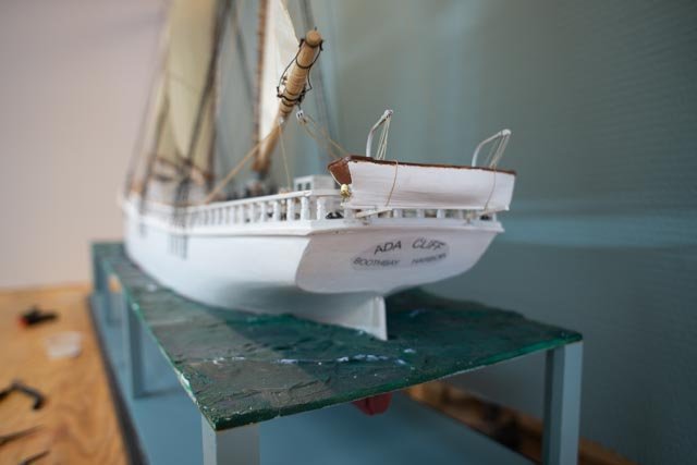
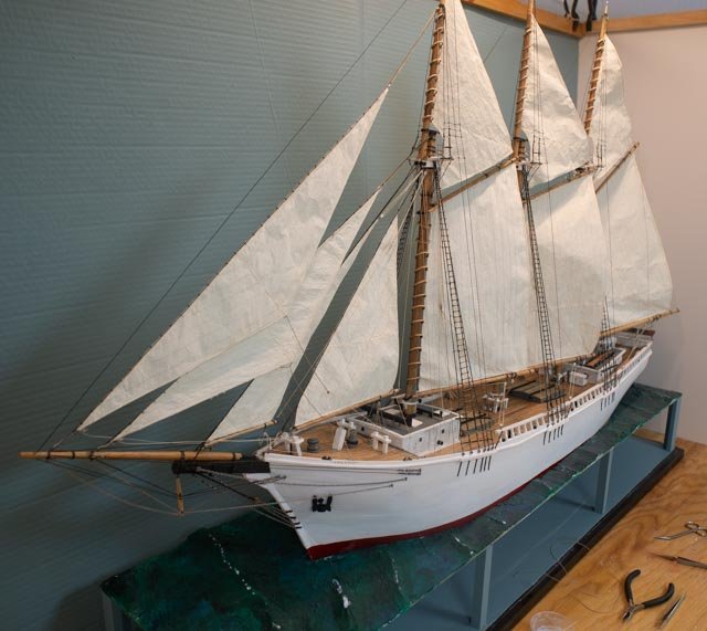
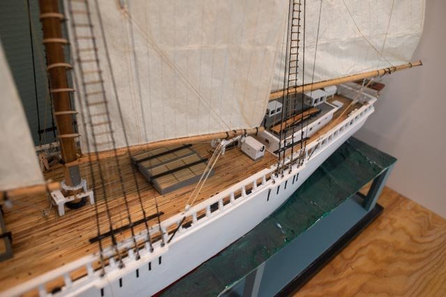
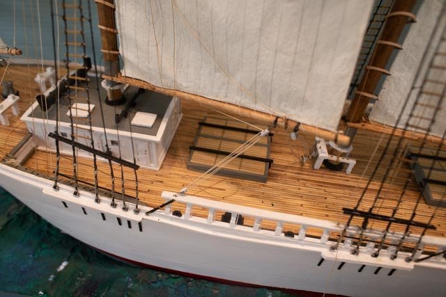
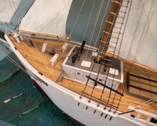
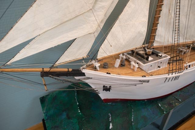
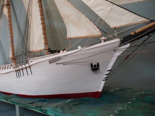
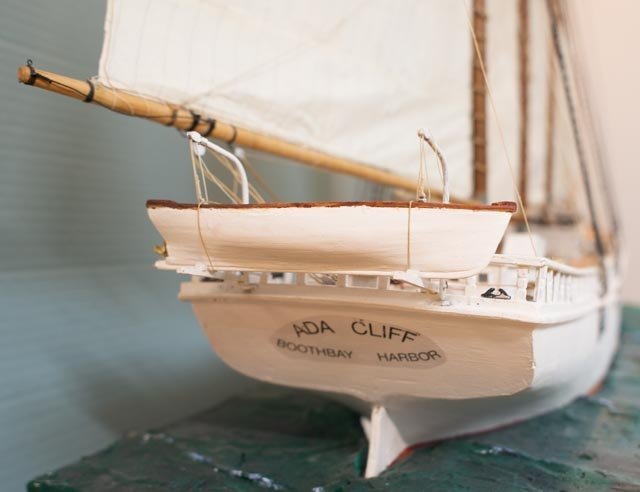
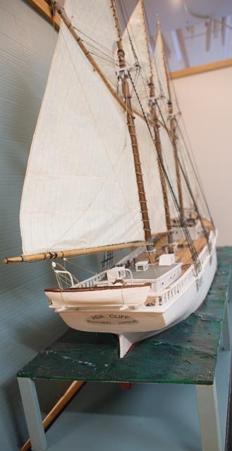
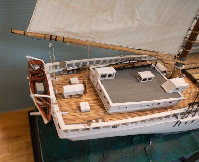
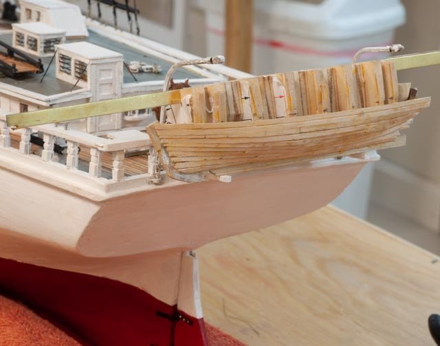
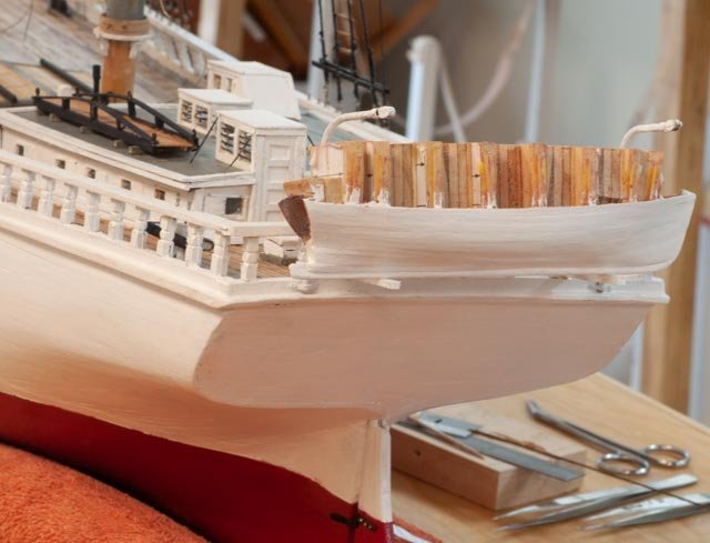
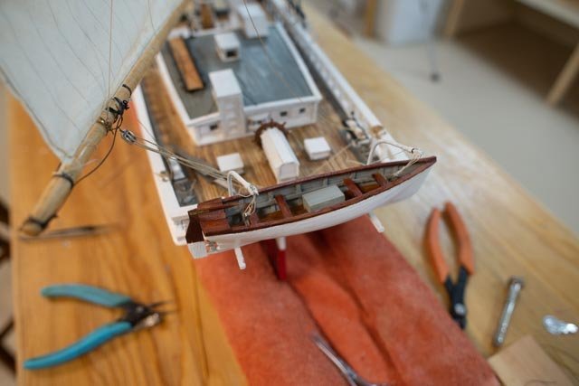
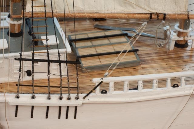
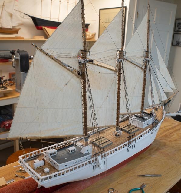
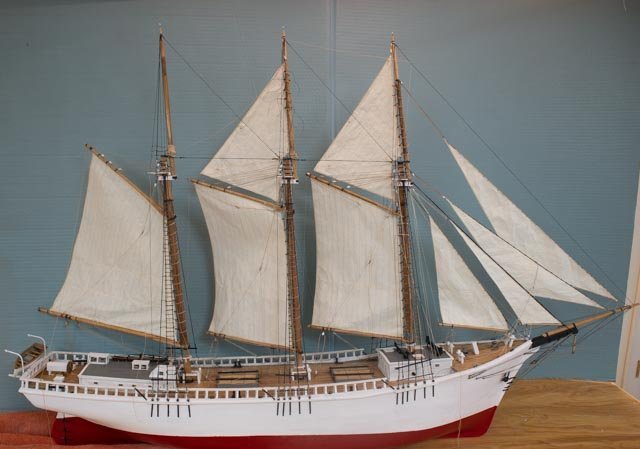
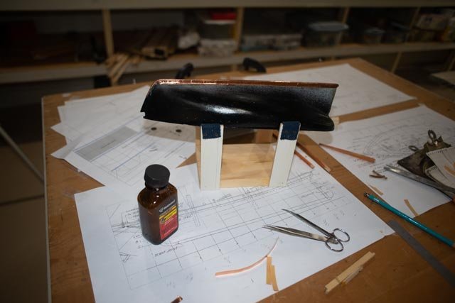
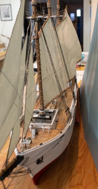
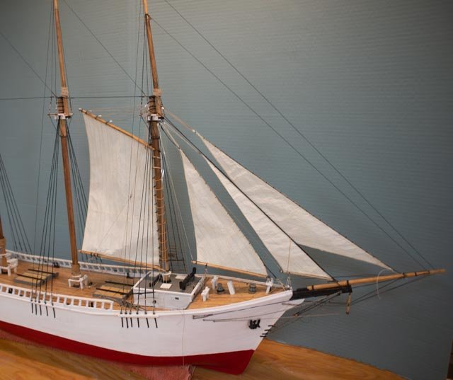
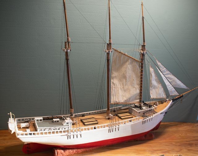
 Post 40. The end….almost anyway I qualify the ‘end’ as it really only happens if the model goes away. I will be using this model for a prop during upcoming talks and exhibitions. I am currently preparing a talk for the summer…The Early Shipyards of Boothbay. My point is each time one takes it out, something breaks or someone makes a suggestion or critique. The following sequences include a case in point of the critic….nothing broke The punch list 1. The name on the transom. I tried to get better cut letters and was told they were too fine. We talked about it at the modeler's guild and I got dizzy with the advice. For now we stay with what were have. I may try to razor cut the film around the words to reduce the area of the shine. I feel it is better than trying a white background. On black vessels, I find less of an issue as a black background blends in more easily than the white. 2. There are about 50 more coils to make; I am now down to two. 3. figures. I got a set of WW II German air force ground crew and have rough painted them. I will clean them up a bit more and leave them on the deck for set up . Their hats were hard to file off neatly. 4. There are always things that benefit from a clean-up a touch up. 5. hatch covers see below...now done 6. a little fit to the stand was done. A few chips on the side showed up as well due to the move in and out of car etc. That stuff will be ongoing touch up I fear 7. Complete research….has progressed and shifted. I was asked to give a talk on the local shipyards, so I am off in that direction. The hatch canvas, coils and crew 343. as a memory view the hatch covers are 6 panels dogged down with the stongbacks. We have read that if sailing these covers had canvas tied down to keep out water. So the challenge is how to do that finding no images of a covered hatch. 344 following the lead from Keithaug, I looked up a few alternatives for a tape product. The ripstop sail tape he recommended available here seemed to be very smooth. I found that athletic tape that one wraps a hockey stick or tapes an ankle in a football game might work. I happened to have an old roll too. Here it is on a dummy hatch cover used to select the material. I used the same paint used for the sails ; more as a wash to improve the look. The crew has shown up too. 345 Here is the first attempt of rolling out what might have been three overlapping canvases, and resetting the hatch strong backs. 346 in this view I have washed the tape with diluted paint and added tie down lines. The tie down lines are truly a guess. 347 Here the hatches are both in place and the crew is starting to get ready as well. Most coils have now been added to their belaying pins . Off to the Downeast Shipmodelers guild as test of transportation logistics, travel dings and critics. 348 Everyone loved the sails ,as few of us have used the silk span before. Then I got nailed…..truly 349 see where I had comeback and raised the bow and fixed the decks and all of that work. If you look across the deck just forward of the bollards, you can see the waterway starts going up. Well silly me had the waterway go through the bulwark outside and oops….see the angle. 350 here I am a few days later trimming off the waterway outboard and replacing it with a swept extension. No hard feelings it will look a lot better. So here I leave this build as “complete”. With my previous qualifying comment Off to the next project jon
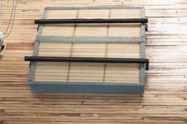
-
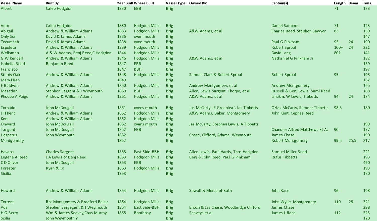
I have just changed the purpose of this build and will be planning it for re start in the early fall. Here below is a list of the 32 Brigs of Boothbay listed by date. I am working on several research projects studying the shipyards of Boothbay. This database of 550 vessels built before 1920 is a start. Over the next few months I will highlighting some of my findings here. The first candidates for the older brigs, would be Veto and Wellsman to fit the scale of the Kate cory hulls I am using as a base. That selection also would cover two of the major builders. the next choice is Scillia as it was built in the main harbor.

-
Keith thank you for the tip I am off sailing in Florida as it is 10 degrees f at home. I will definitely try this approach when I get back cheers
-
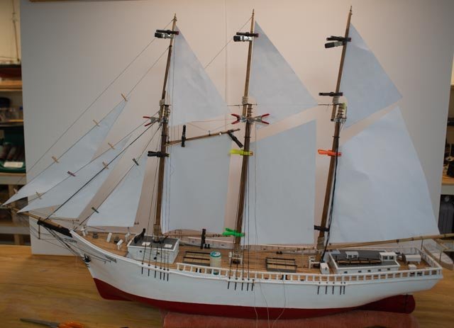
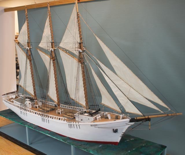
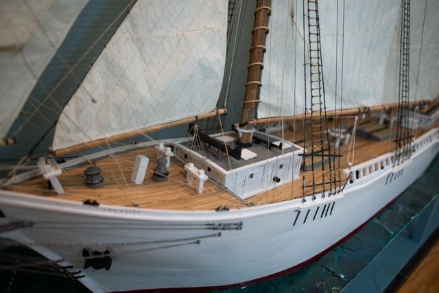
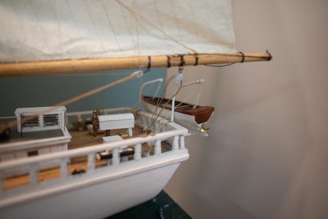
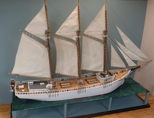
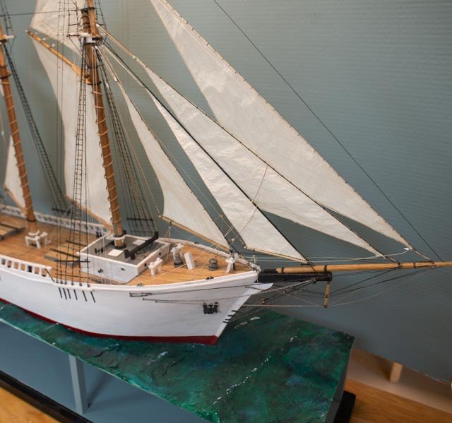
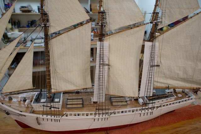
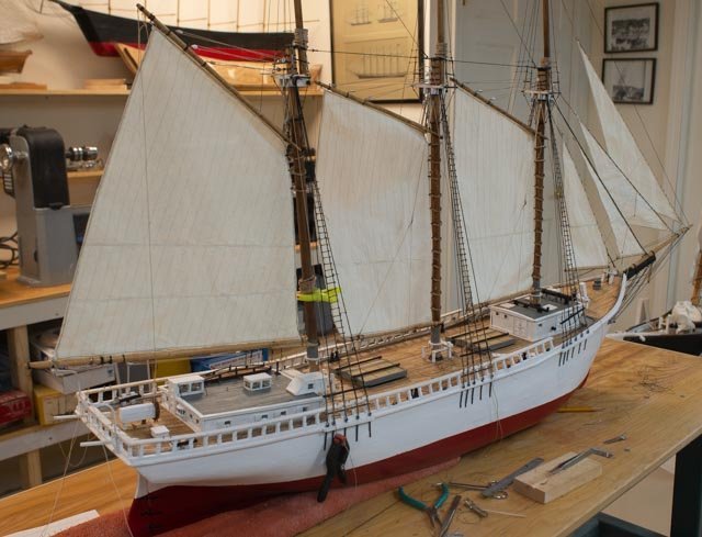
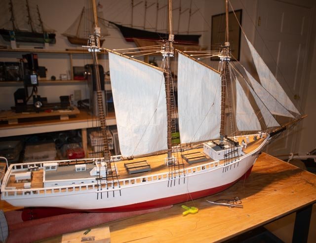
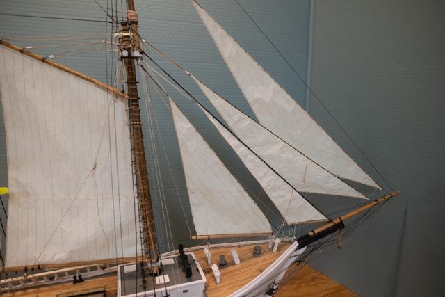
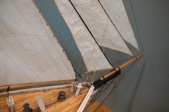
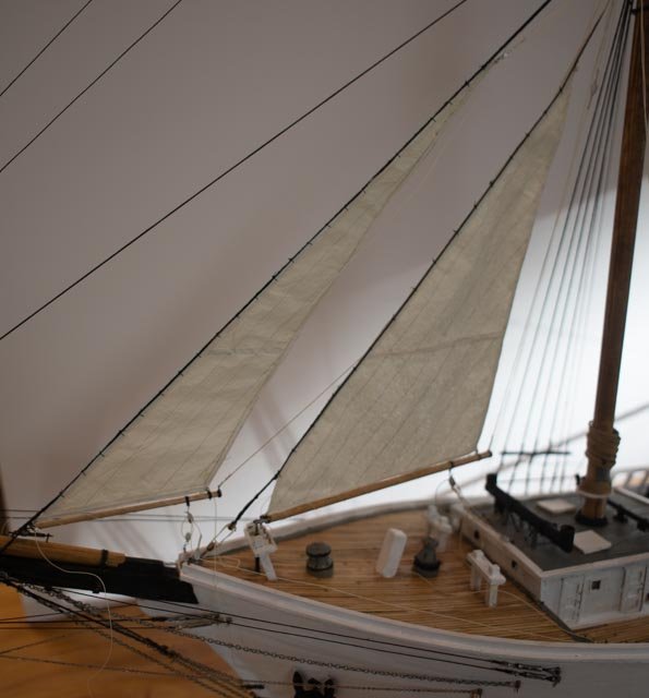
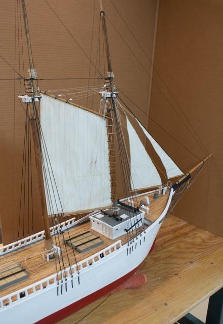
Post 39 We are in the red zone, and I can see the goal line This may be the second to last posting. To add more than a finish record will come only if I find enough history to add a story of the life of Ada Cliff after she sailed away. This posting is to record a bunch of pictures of an almost complete model. I said once the ratlines are tied off, I would consider it done other than punch lists. I found yesterday as I worked away and completed the ratlines, about three things broke. That means each time I do some work I am likely to break something else. I also feel completion will include taking the model somewhere and setting it up for discussion. Then I need to bring it home and fix what broke during the effort. That trip is next month to the guild. I see no need to discuss each photo in this posting. There are a few things to point out that make up the punch list. In general, the photos show Ada Sailing first from windward [ starboard ] and then I turn her around. One focus is to show the tackle rigging in use. The sails clearly hang, so I am following advice from Keithaug that it is afternoon, near the cocktail hour, and the wind has fallen off. Maybe I should paint out the few white caps…… the punch list summary 1. The name on the transom is clear sticky label stuff with my printer going to work. The problem is the ink is not set well, so if one touches it , it smears. I have ordered the vinyl letters like I have used before. $20 bucks more. This issue I think is that black sticky stuff on black tended to work in the past but here clear shinny of satin white does not. 2. There are about 50 more coils to make and tie off and few lines that seem twisted or crossed to be undo and rerouted. 3. I have not yet purchased or planned for figures. I typically use them in a permanent display. I will take some for any showing, but as this is not a diorama so to speak, they are currently missing. 4. There are still several things that would benefit from a clean-up a touch up. 5. I may…that is may ….take some silkspan and try to cover the hatches as they would have been canvassed while sailing. More likely I will try it and if it works do it, and if I looks dumb just forget it. 6. Make a little better fit of the hull in the sea. 7. Complete research….that will fall into future studies I think…. Anyway, we are off to warm Florida for a week reprieve. I am clearing the shipyard for the reactivation of Dancing Feather a combined rc version refit and a small scale study model. I want to get them done and then next fall onward with the next Boothbay build. Here are multiple photos tagged ac 342
-
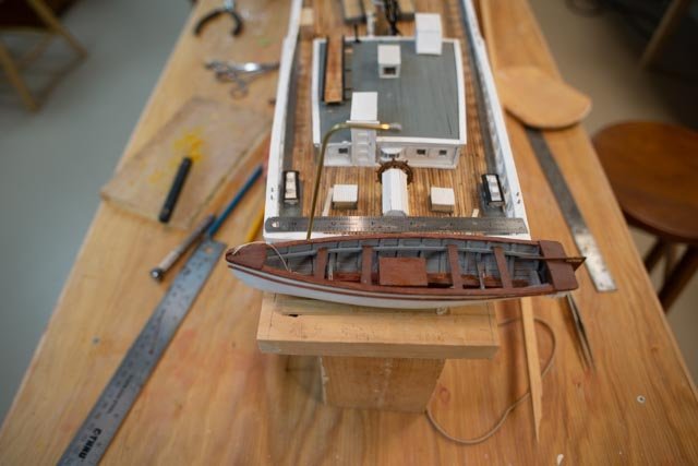
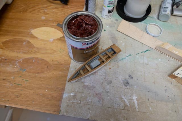
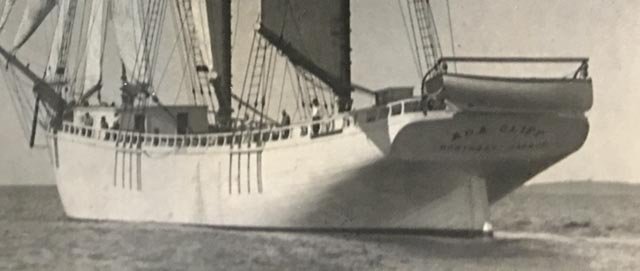
post 38 the yawl boat etc. first let’s finish the yawl boat 333 picking up from before, we see all the planks on the yawl boat. 334 here we are all cleaned up the mahogany transom and the white planks. 335 here we celebrate removing the mold with relative ease. Now what are we trying to do on the stern to match the photo? I have restarted my Historic Society research. I am gathering the story of all the older Boothbay shipyards and the vessels. I’ll do more on that in my blog next winter. I got a much better resolution for the photo shared before of Ada Cliff sailing away. 336. here in the cropped view where we can see a few import issues. The hale is clearly Boothbay Harbor. That is of interest as many Maine built schooners were for other markets. I hope to find more history about her ownership now that we can see that it was very local. The owner was the mayor of Somerville, Mass that brought the money to buy the yard…we’ll see where that story goes later. Looking at the yawl boat there is a single gunnel. The overhead plank is seen on another schooner to have oars slung below. This one does not, and the yawl rudder does not ride in place. 337. here we have the yawl boat resting in place. The hard wood I used is very light in color, it’s like teak. That would not have been used. 338. Mahogany I have read was the marine wood of the time. I have some mahogany rub in color used for bright work on a real 1941 sailboat I had restored a few years go. I am going to try to use it. The paste did not work out well, so I mixed in some gunstock stain with it and hopefully captured the color. The point is to show...it was 1917 and the bright work would have been mahogany. It’s not perfect but better than teak. I had carefully attached the rudder, but it looks like I need to detach it and set in inboard. A few more details going on as we get near the finish line. 339 I mentioned last time a hoop broke. Here is my fix. A little AC and scotch tape on the inside of one half then more AC and the other piece with a few prayers and it came back together. 340 this detail comes from Douglas Lee [ Maine Maritime Museum}and his study of many similar and bigger schooners. In his drawings he includes the diagonal strap to hold the load of the boom tackle. I compromised by adding just the bracket and kept the staple. These booms are roughly 32 feet long. In the bigger schooners the booms were often more that 40 feet long. I may have overkill here, but I want to show the logic of the boom tackle in action. 341 I shared this view with a friend today. If one wants to count, there are roughly 730 knots to tie the 300 slats [ in lieu of ratlines] in place. I know anyone who built a ship model would call that pikers work, but to us schooner guys it still seems like a tall hill. I am using these last two as the barometer. When they are done in a few days I will consider I have moved from building to a punch list. there are roughly 60 lines to connect, lash and provide coils, and lots of clean up touch up and then to set her back on the ocean stand. Cheers
-
Hi joe I have gone through your log a few time and applaud your stamina. I appreciate your kind words. I am now a week away from the punch list phase. I am already looking at the next project ,but more importantly diving into deeper research at the historical society on the overall early ship building in our harbor. I will be sharing some of it in next winter's project which is planned to be three brigs of boothbay. cheers
-
Keith I had fun looking through wikipedia and others to see if there were a sailing angle to you suggested phenomena diaurnal variation . Alas there was one here in maine is is a rare eventing for the wind to come up like you describe. What we experience is mid day through the afternoon strong onshore sw breeze. that is what made it so easy to go " Downeast". the Downeasters were square riggers fat and happy . many built after the Clippership rage ended. I agree with you about the early morning blues. fortunately for me, when I come into the shop in the winter morning, and the sun is out, it shines right in on the model and is a joyful wake up. that's the good news. the bad is it highlight many things . cheers
-
I quietly come over here many times to get inspired, and then like today with freezing rain and sleet hitting the windows get overwhelmed. You workmanship is a joy especially on a winter’s day. please keep sharing jon
-
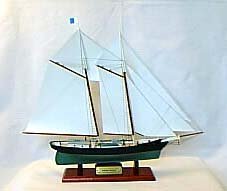
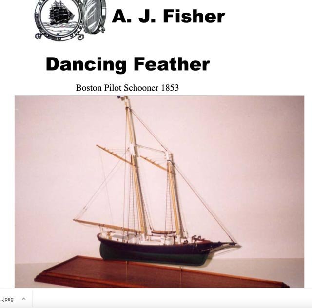
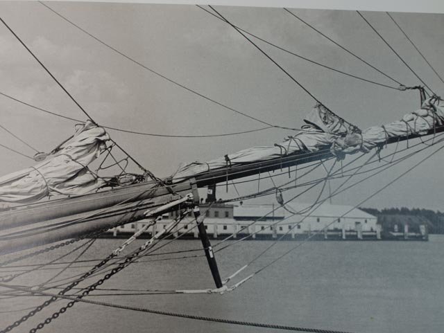
Roger the model I saw was in the store named Piel Crafstman. It was 2001. This image from the piels Craftsman website . I feel confident this is the model, still on their site , that I saw in the case in 2001. It showed all the sails set. Surely for a race. if one goes to the site today and then switches to AJ Fisher.....it is the same store. They have moved apparently from Newburyport. this image is from the AJ Fisher website .....They now show a new model that does not include the top masts nor topsails. it is set up as I am finding the consensus to show. on their website today they credit the model to...... Al Blevins. I am thinking this view is closer to what I am aiming for. the NRJ 1988 article has a perfect image and I will get into that next month as this project truly begins again. cheers c
- 23 replies
-
- 4
-

-
- dancing feather
- pilot schooner
- (and 1 more)
-
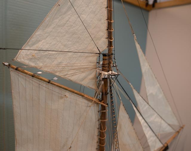
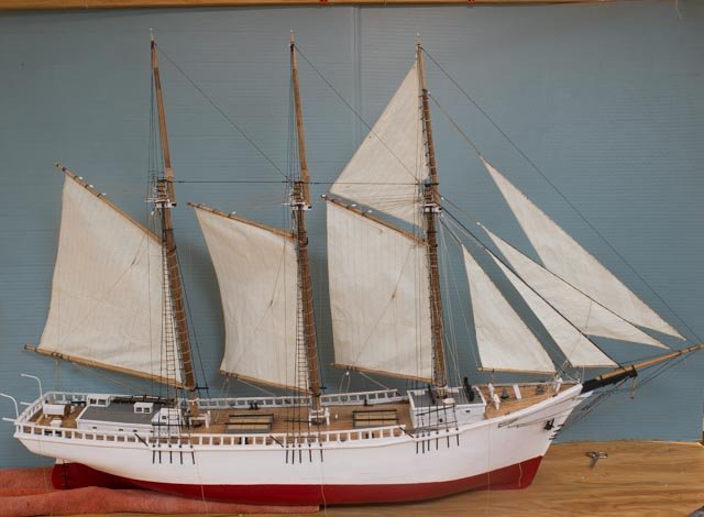
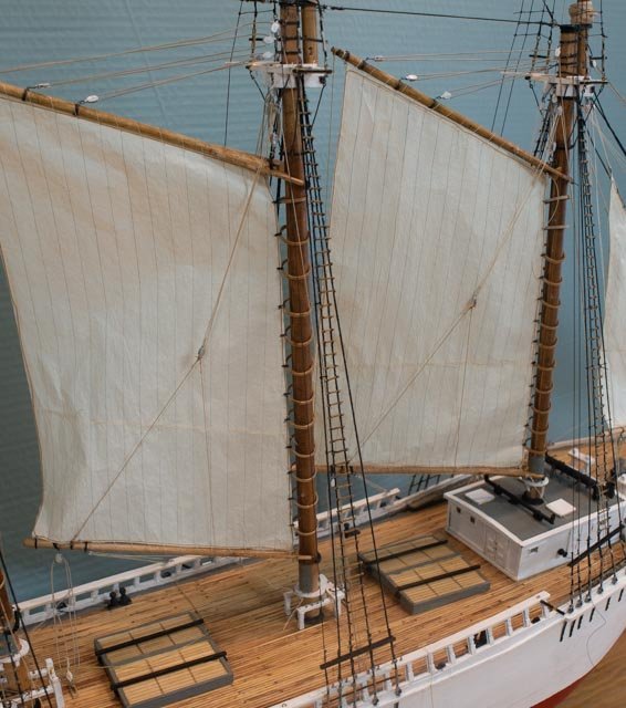
Post 37 Complete bending all the sails This post gathers the last few updates with this final viewing of all 10 sails being bent. Yippee… Our recent blizzard made it a lot easier to finish setting the sails. There is now a ton of work to get the rigging all done, tied off and their coils hung. Here they are 330 the 8th. sail 331. the 9th. The yawl boat is coming along and sitting in place too. It will get its own posting next time. 332 the 10th and final sail. This one had everything possibly go wrong. The halyard came off, the sheet chain broke, the stays had an issue and while fixing them a turnbuckle broke. Putting in the very last seizing for the last hoop, the sail ripped. I defeated the gremlins and there she blows. Just in time for Chinese New Year.. cheers
-
Keith thank you for that encouraging rationalization. Living and sailing here in Maine each summer, we know well about 5 PM and the wind dies. cheeers
-
Thank you Roger. I found that by setting up the cds on my old windows machine I could eventually get them on my new apple hard drive. The new imac sees them just fine. I also found right next to the Dancing Feather article part 5 of an incredible treatise on the fishing schooner Elsie by the master Ronnberg. I will savor them all as I found and then saved them to my fishing schooner library for future reading. I will study the article on DF and add that to my thinking process of what i want to represent in the study model and then the potential RC version. In a quick glance it seems he found as I have that all those sails shown in the sail plan were just not practical for the work of piloting. more to come Thank you so much for giving me the heads up cheers
-
Thank you Roger. I will research them. I have all those cds with old issues. My new apple iMac has no cd drive but I’ll figure it out. I believe all the indexes are on pdf so I can find the issue that way as well. I am researching a brig the Torrent that way as well as it is my d build next winter cheers
-
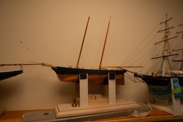
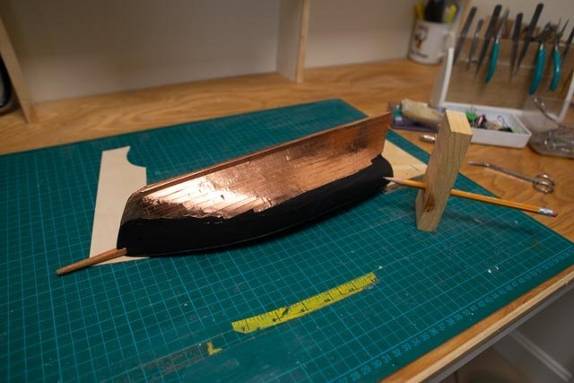
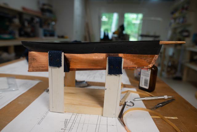
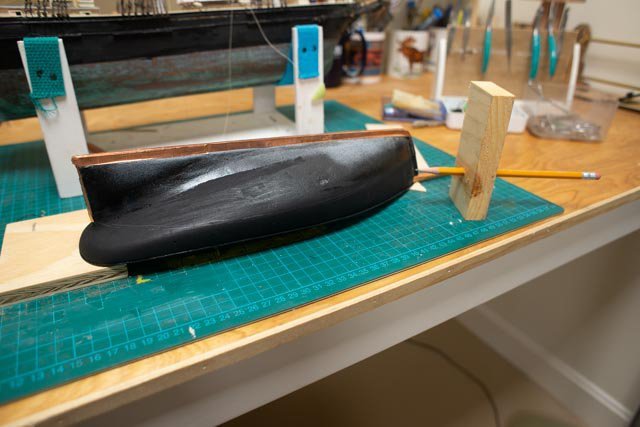
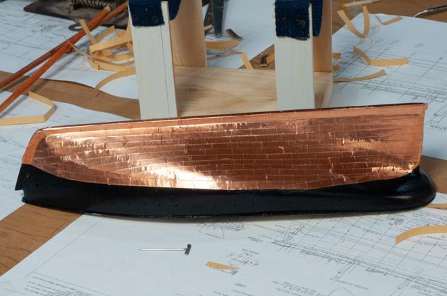
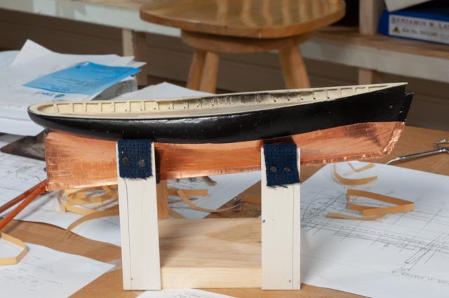
post 8 That last post I did on this build was June 2020. At that time I was introduced to the opportunity to model Ernestina Morrissey , as the real one was being totally rebuilt in Town. After the schooner Ernestina, along came the three masted schooner Ada Cliff ,and we lost another year. This Dancing Feather build was put aside that summer. Before leaving her, I did the copper bottom and fixed the hatch on the main cabin. Here are photos of the coppering that I took in July 2020 as she was being put to bed for a while. I still find that working with the copper tape is hard to do, so I am humbled by what I see in so many other builds. I can never get the tape to stick on its own. Photos 207 to 212. Copper tape for the bottom 213. Finally, here we see her sitting on a shelf where she has been patiently waiting for a restart. I am completing Ada Cliff over the next month or so and have been advised by the admiral that the bigger version of Dancing Feather looks like a wreck and needs to be salvaged or removed…..I guess we know what comes next. Stand by work is coming soon.
- 23 replies
-
- 3
-
-
- dancing feather
- pilot schooner
- (and 1 more)
-
the seventh sail…… 327. here we have the spanker bent. 328 here we see the running lines and ratlines and all that fun stuff coming together. In this shot I have engaged the boom tackles to try to better set the sails. 329. here looking down the port side we see the boom tackles engaged.
-
a little progress as the missing blocks came in 326. the sixth sail , or i should say the main is bent.... i am now thinking that I may stretch out the boom tackles to see if that helps with sail shape. i am nervous at this stage to treat the sails with more material. despite the look they are delicate. cheers
-
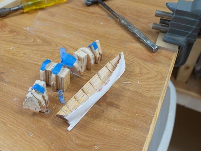
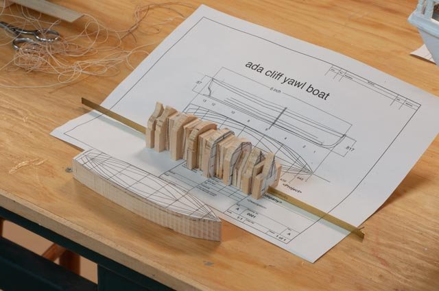
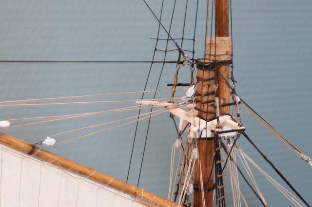
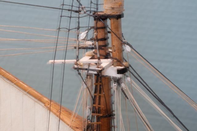
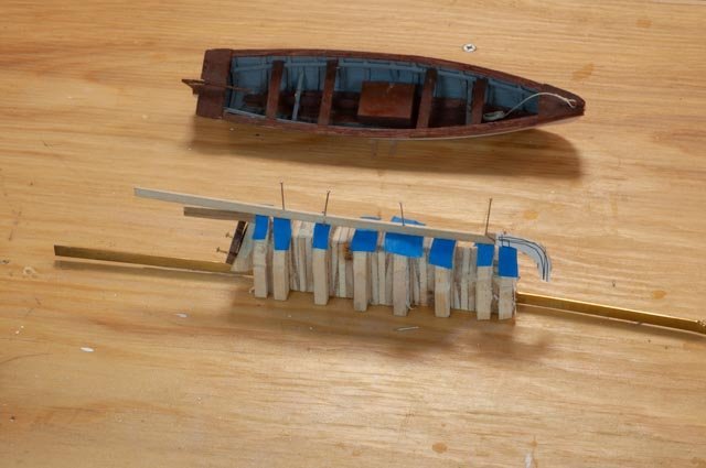
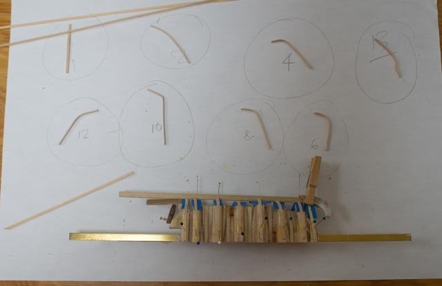
post 36 start yawl boat and complete foresails Moving along I find there are so many different tasks. Each new task takes a time to start up. Example is the yawl boat. Last fall I decided to follow the lead of family members and switch from part windows, android and apple iPhone to all Apple. Wow. It is not just a smooth move. I kept my older windows set up in the shop so I could continue with the turbocad I owned. Starting with the yawl boat, I had decided to buy turbocad for imac. It is like studying French for three years and 20 years later moving to Brazil where French does not help with ones Portuguese. I know that example as I lived it 10 years ago. I now have several guides and some friendly advice. The apple version is very different from the windows version. First up is the yawl boat. I will do it again in 3d, but to move forward at a reasonable pace I chose to work in 2d. wow the apple version does not like 2d. 318. here is a printout. Apple is definitely for the modern world and is not sympathetic to 2d. nevertheless, I eventually got there. I had 8 stations and the plan to work with. I made up thick stations and added fillers to get close enough to the right lay out to move forward. 319. here after satisfying the set up….small mahogany transom included… I have prepped to add the ribs. 320. I soaked 1/32 ribs in water and let them dry before gluing. Here the starboard side ribs are glued We’ll see how it comes out Rigging the fore sails......There are many different visuals to refer to when researching each part of either standing or running rigging to determine what material to replicate. 321. In this photo from the flyirails book one can pick up the sheets that wrap stays for the flying and outer jib were chain. One sees here the small rings both on the stay or the flying jib luff that are laced. Before jumping to emulate that detail, one sees the bob stays in this photo were spun steel cable. On the Ada Cliff photos, one could see they were chain. The omega hanks that I have assumed avoid the lacing of rings on either sail or stay. I would imagine a pulling and stretching of the lines involved and a very difficult task to improve. The sail could pull back from the stay, not a good feature. Therefore as others have said better than I , one needs to decide what makes the best sense and what therefore is to be modeled. 322 I used the chain bob stays and the omega hanks and chain for forward section of these jib sheets. i will paint the chains for a galvanized look 323. here all the forward sails are in place and running lines are in and made fast. the ratlines are in as well. 324 here looking at the fore mast top all parts are in place. 325. in this view one might note the farthest turnbuckle is unpainted. That was the barrel I had to replace to get the little brass bar to fit. Ever onward. Main mast is next when I get more blocks
-
Thank you Keith...it continues to be an adventure. I have other adventures like copper tape on the bottom of some started brigs that still baffles me. I will be back on those next winter....I hope I may make them water line and add sails. cheers
-
One should not to be surprised, things slow down a bit at this stage. Rigging, making sails, starting the yawl boat. Moving forward, then oops, then fix then move forward. Today I found a turnbuckle did not have enough open space to receive the little brass bar. Everything around it was done [ that was the oops]. I had to undo it, eventually cut it out and make a new barrel, so I could get the little bar in. knowing sequence is truly a master’s skill. Then later today I punched a hole in the spanker. Perhaps the patch makes it more realistic. Smile! I made up a topsail and the realized it was the wrong one. I am waiting for more Bluejacket blocks anyway, so no lost time there. On we go 315. here is another sail on 316 this one is fun playing with winter morning sun light. the blue background is just a big box cardboard. I am still trying to figure out how to take more useful and fun photos. Blocking the shop as a background I think is a good first step. cheers
-
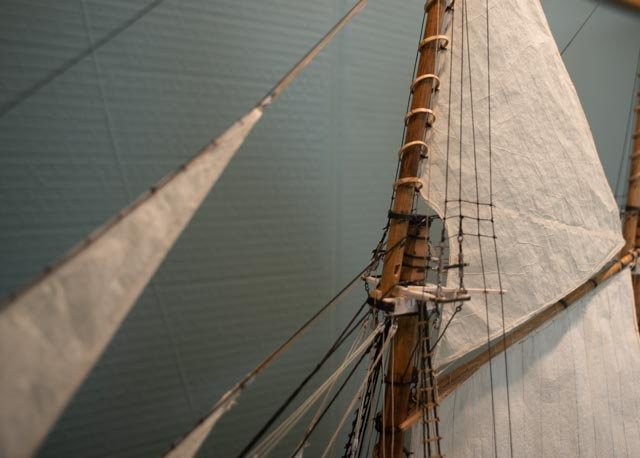
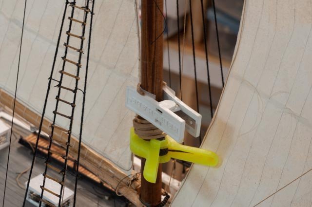
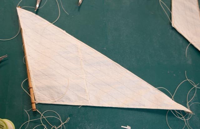
Post 35 Making sails part II getting the sail trim process figured out and the first few sails in place. Thanks to my daughter’s vacation we got all the sails roughed out and started trimming them. After the fore sail we learned to cut out the sails roughly 1/8th too big. They were then marked on both sides. We used a homemade light table to do the second side. 309. here they are all cut out and lined Next up was the trim work. The process that I have followed included the following: • Cut many strips just under 1/8 inch. • On the port side I ran a combination of strips and strings on the edges. I covered the stings with cover strips. These stings extend at each corner for connections. • On the starboard side a ran strips and then glued a bolt rope. 310. here I am doing a little of each on the first three sails 311 here the fore staysail is lashed to its boom. In my past research in Lunenburg, Canada I learned from the captain of Bluenose that the method for bending sails on the recent re-build was copied from the original. That meant the omega shaped iron hanks for all jibs and black wire wrapping the luffs to hoops that I saw was the way to go for 1921. At my 1:24 gauge Bluenose build, I was able to make little black omega hanks and sew them to the sails for the jibs. Here they would have been too small, so I simply used black thread. 312. here we have the first two sails tied off to their stays . 313. here the first gaffed sail is in place. 314 I am trying to work all the related running lines with each sail as I go. I found that the combination of the bolt rope and internal string and several strips gave a secure luff for sewing the hoops in place. So far all is going much better than I feared. All for now
-
Thank you Tom Now that I am installing them I have become a convert. I like working with silkspan and the ability to get something the first time is very encouraging. I can even think about covering u one of the hatches as they would have been under canvas when sailing. we'll see. regards
-
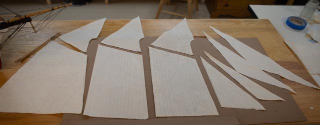
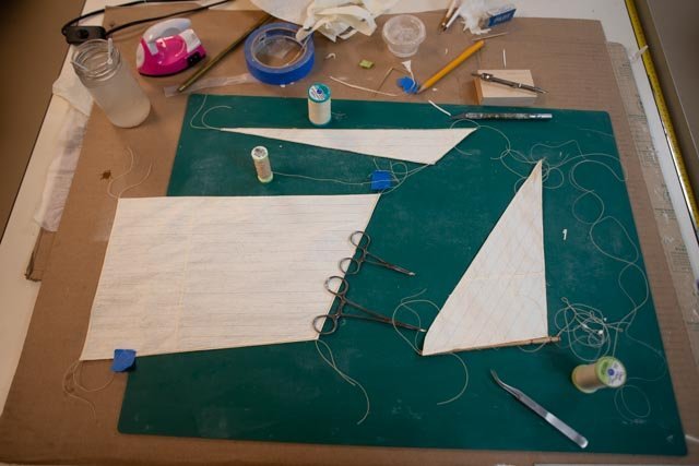
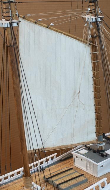
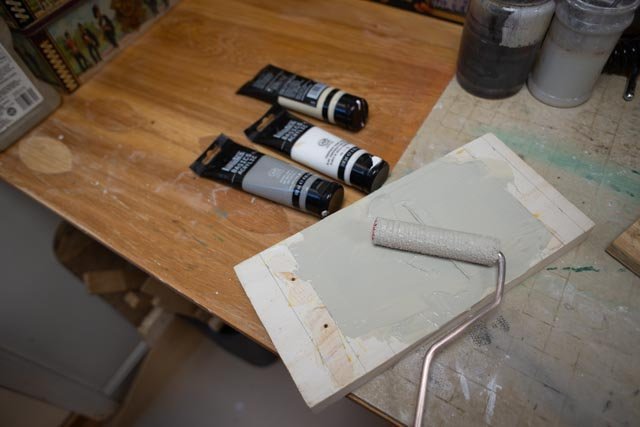
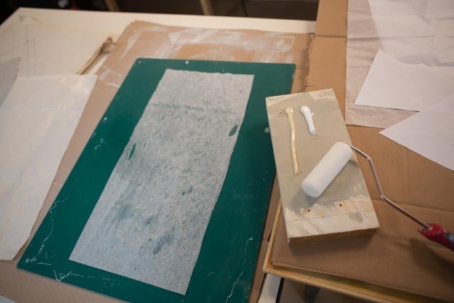
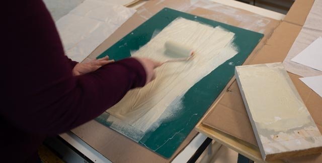
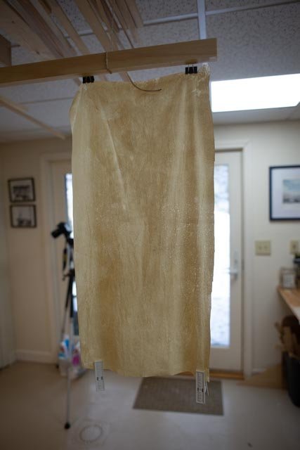
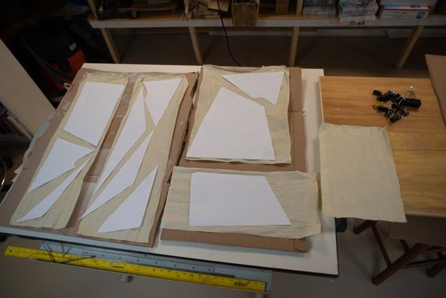
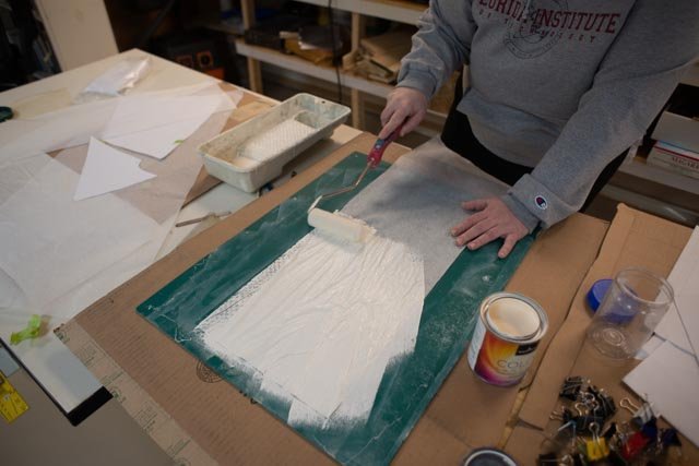
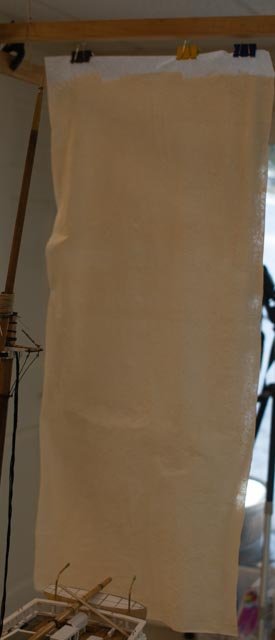
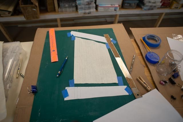
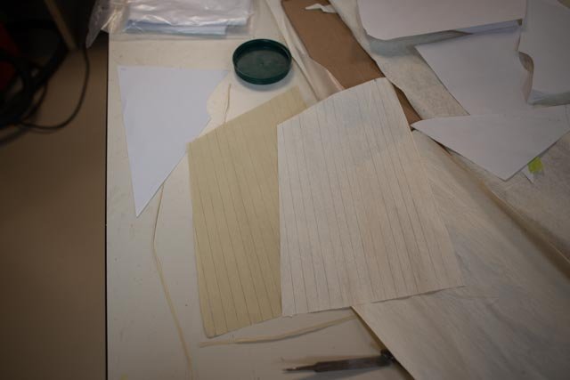
Post 34 Making my first silkspan sails part 1 paint, its color, etc This episode has been and continues to be an adventure. It went quicker than it might thanks to my daughter coming up to spend Christmas week with us. Last year she got me through updating all but one of Bluenose sails. That wa on the sewing machine, This year we worked together, figured out our method, not necessarily the best, and got basic production done on the ten sails. She loved painting hanging, then cutting them out and drawing those nasty little lines. I have to say it took two to do the larger sheets. One person I believe would be limited to sheets much smaller and only one or two at a time. Here is the trial-and-error method. It followed advice several ventures onto u-tube and other blogs to find several “experts”. It is not surprising there is quite a range of procedures. The main choice was to follow one of the basic options. I had followed the suggestion and bought the book for Sea Watch. I read it months ago and now have no idea where it went. • Several experts laminate silk span over marked up copy paper. • One expert showed making the sail with one layer of silk span. There were discussions on different choices in thickness of the silk span. I simply got what Bluejacket supplied and it worked great.…..we liked the one layer approach and went that way. Second issue is to choose paint method • One expert said take acrylic artist paint, mix the color, spray water and then and roll it on. • One expert said take a spray can and spray it on • One blog said latex works just as well as acrylic. That means one can get a pint premixed and be sure of common color and have enough to do many batches. Also a Pint of latex is the same cost as maybe two tubes of acrylic, and living here in Maine it is a 45 minute drive to the nearest store that carries it. First up is the first method of using artist acrylic 300 here we are mixing three tones. We knew we wanted ecru but were unsure if we needed grey to the mix. We did one sheet and quickly switched to just ecru and white. 301. here on our third attempt we spayed the right amount of water remixed without grey and went ahead. 302 here my ringer guest is going at it. 303 here is this first batch drying. Boy we lost a few sheets in this process and this one is a bit blotchy. 304 here we laid out the sail patterns to see that we were making the right amount. We decided to reject this batch as there were inconsistencies and other beginner problems. I now have plenty of use for the material on smaller models at some later date. We took a couple of ecru and off white spray cans and tried a few sheets. we found they became shiny so ruled out that procedure. After reading that latex would be OK, we reviewed our sample and chits and went to get a pint of what we felt best replicated the shade of light ecru in the color photo 305 here is goes on. We learned it is very different that the acrylic to apply. Hard to describe just different. It is stickier and the time element requires speed as is sticks to the mat quickly. 306 here we are drying. The color consistency was much better. We also learned not to wet nor paint the top one inch of the silk span, so it stays dry and strong for the hanging clips. 307 here is the test foresail cut out and lined. 308 here is the comparison of the first sail made with acrylic including the touch of grey with the latex out of the can. One can see the consistent color and we thought the right tone against the white copy paper for comparison. the sheet under it is the acrylic. Next up is to get them cut out, figure out how to make them up and then get them bent onto the spars. cheers
-
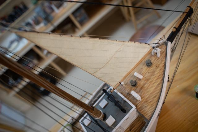
this post is just to celebrate bending my first silkspan sail. it has been a few days and has some friends. it is such a new field I will share my beginner's saga 299. here we are .
-
Thanks Keith It's always nice to hear from folks as we keep keepin on. I am into sails now and having fun. My next few posts will catch up as I now have sails on board. cheers
-
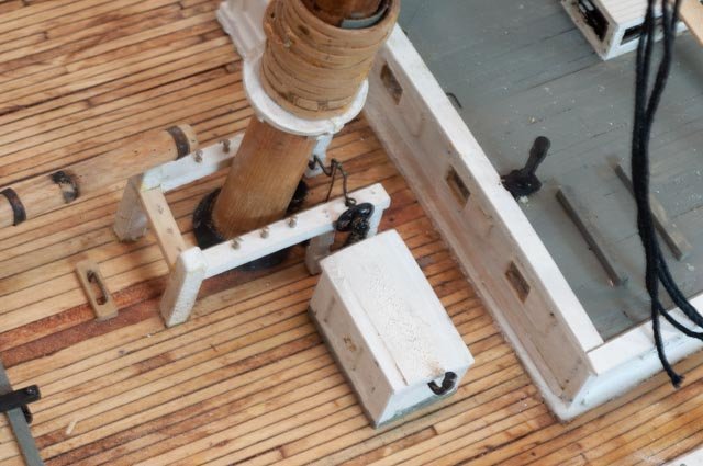
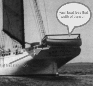
I am posting a few views to just catch up on where we are at the close of 2021. Much time was spent on developing sails as my daughter came for the Christmas week and encouraged the activity. In the meantime work on deck and rigging continued. 293 here I have installed a gas engine house for the water pumps. In the photos of the 4 masted schooners, a box just like this one is behind the third mast. Others had a small house up on the roof of the cabin which was clearly not in any of the photos of Zebedee Cliff. There is no way they were without a motor for the pumps as these girls all leaked. I added a direct chain drive outside the port side fly wheel. Thus the pump could be run by hand of the engine failed. 294 time to turn out the docking bollards and wheel heads for the main donkey engine that hoisted all the sails. Looking for the yawl boat. Most schooners carried a yawl boat. The bigger ones all needed tugs to get into the docks . In recent years the windjammer schooner Heritage uses its yawl boat to move in and out of tight harbors. Therefore, there is some point where the yawl boat pushed the bow around and as the schooners grew in length , a point where they were effectively a launch. 295. here is the sail away photo of Ada clearly showing the yawl boat. 296 here is the yawl boat I built for Charles Notman a bigger Bath built Schooner. The look is ok but too long. 297. using the photo and scaling, here is a roughed out block that let me figure out the davits etc. As we close out the year, we find we are nearly through with the standing rig and getting going on the preparation for the first sail. 298. here we are with the first pass of templates for the sails. More on that later Happy new year