Jond
-
Posts
876 -
Joined
-
Last visited
Content Type
Profiles
Forums
Gallery
Events
Everything posted by Jond
-
 Tim Thank you for your kind words. I agree there is a thin line when a build becomes scratch. The Bluejacket folks are not only local to us here in Maine, they are very helpful too. I use their fittings and things on most of my builds. I believe building from a kit for the first of an entirely new venture is a good idea, and they have nice kits. I loved building Charles Notman. cheers
 -
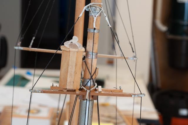
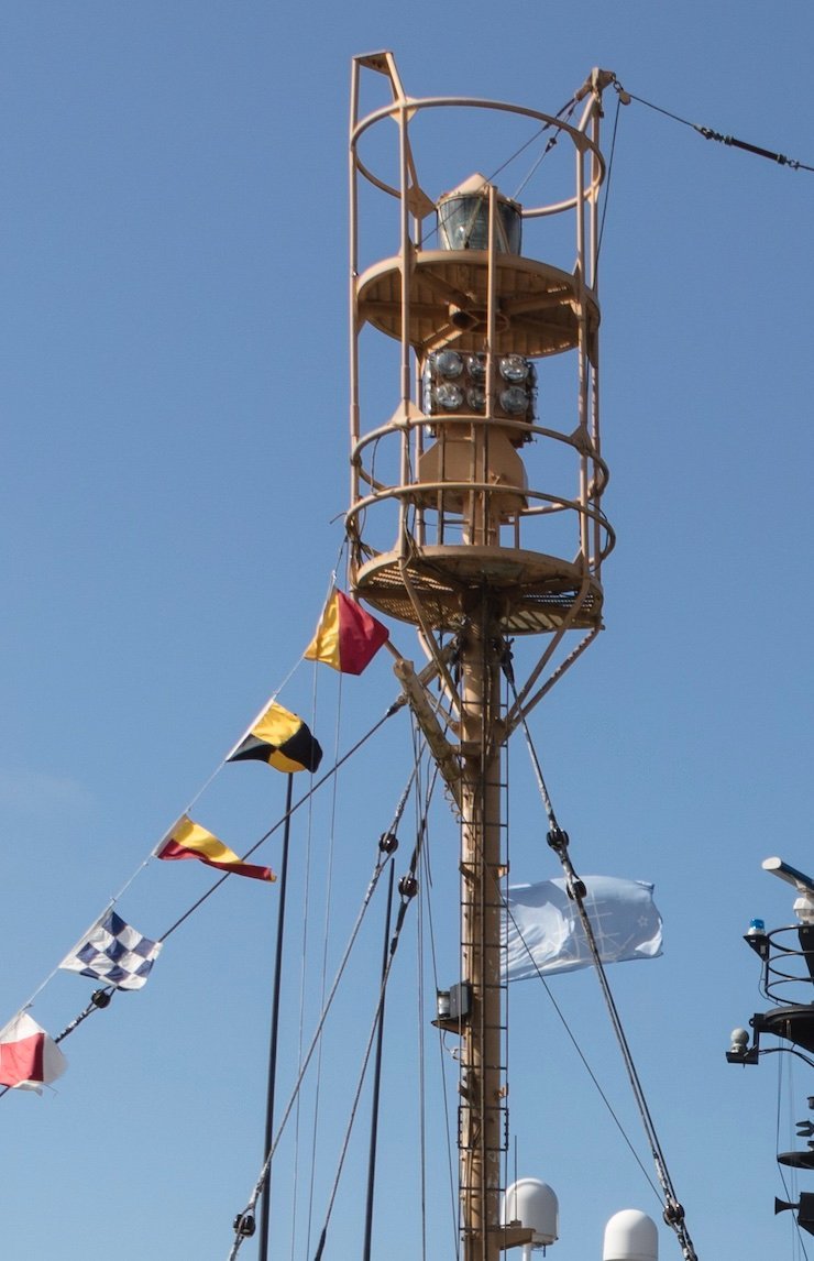
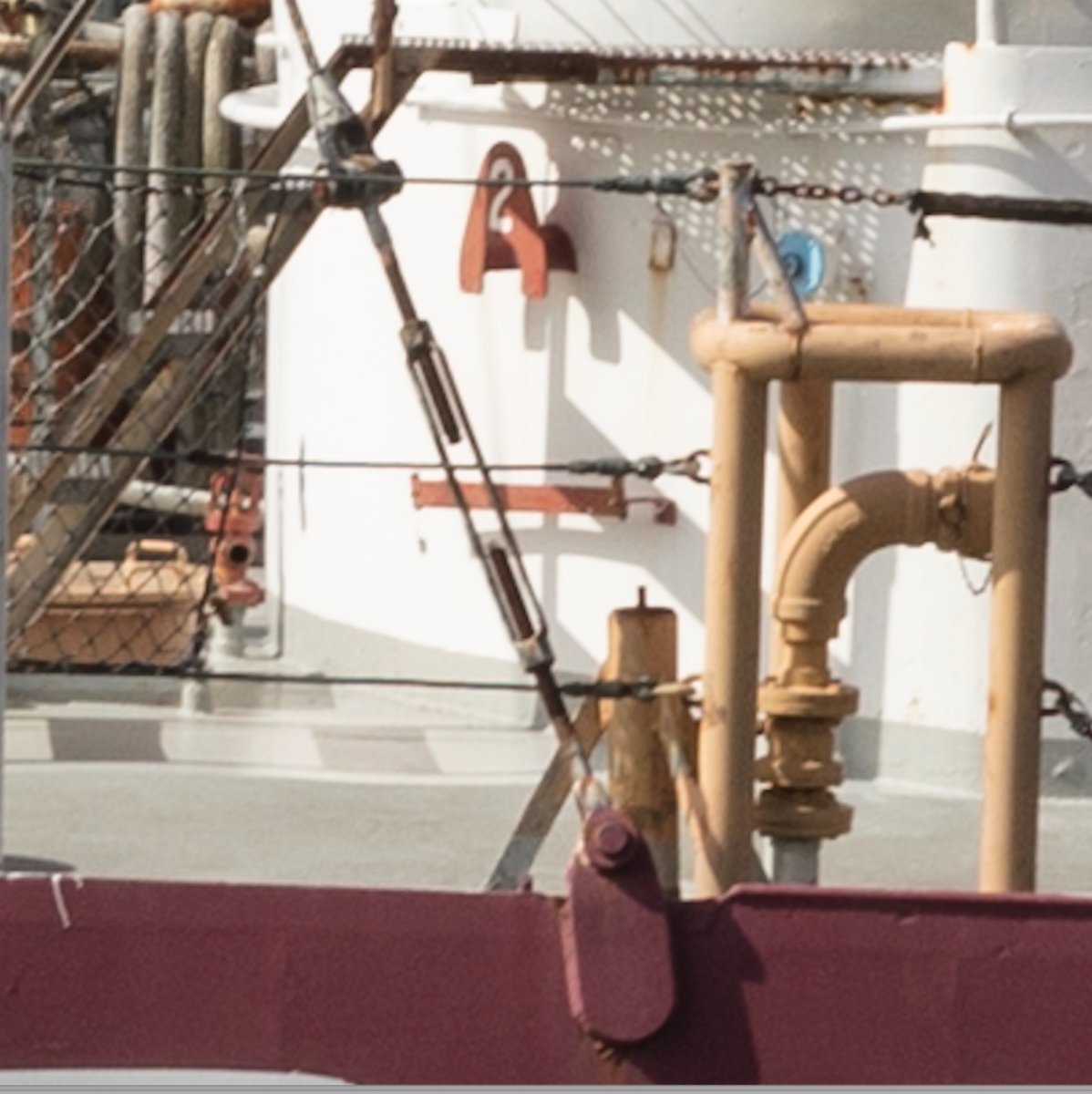
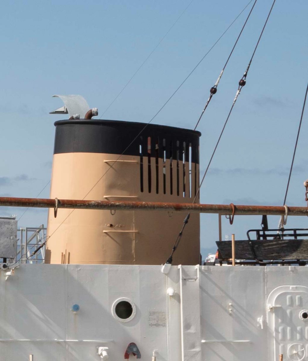
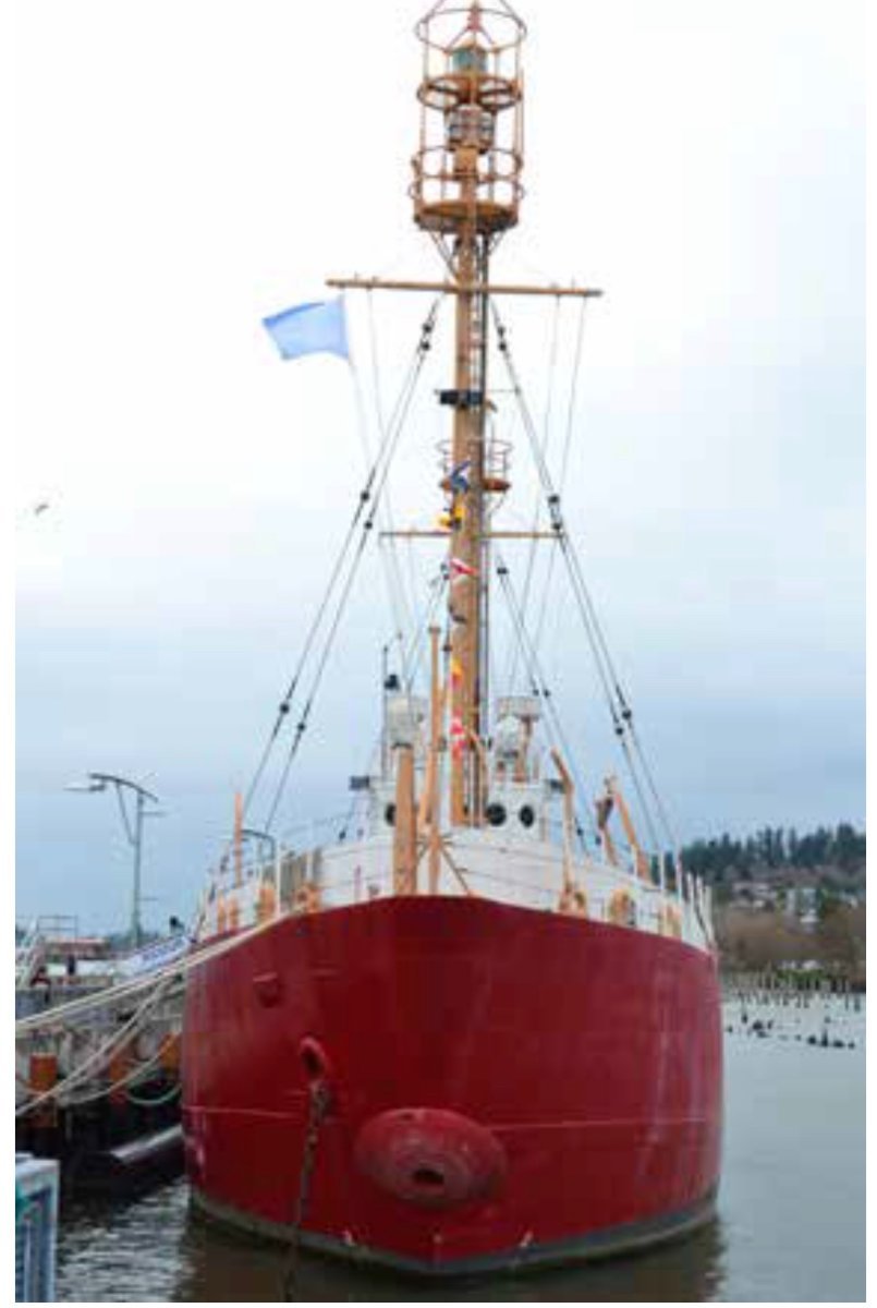
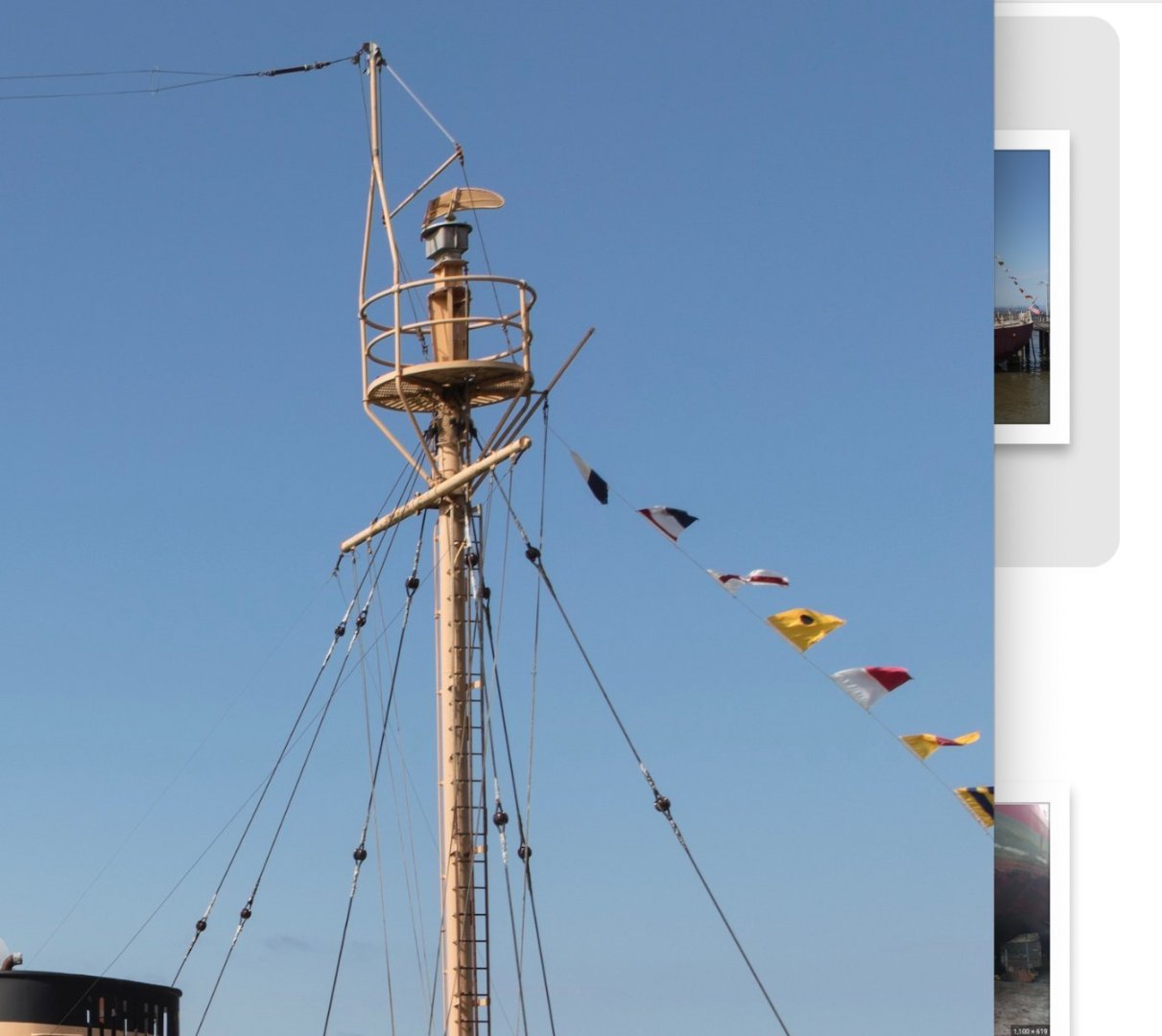
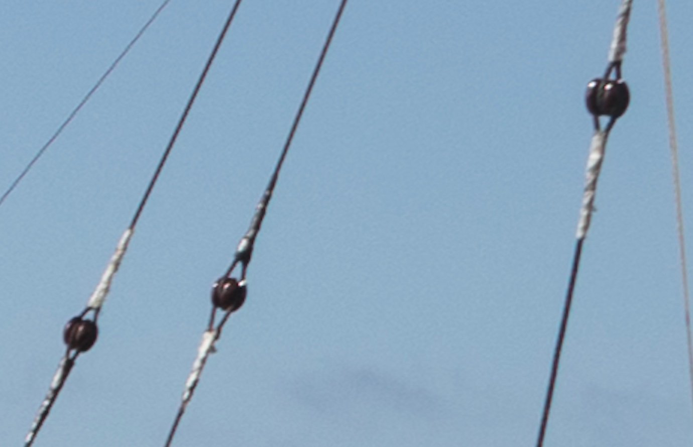
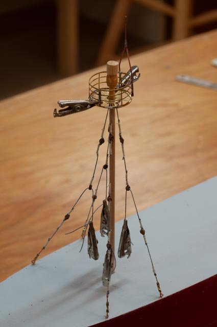
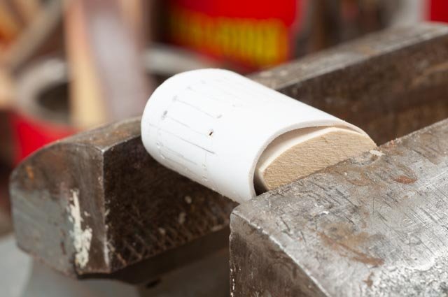
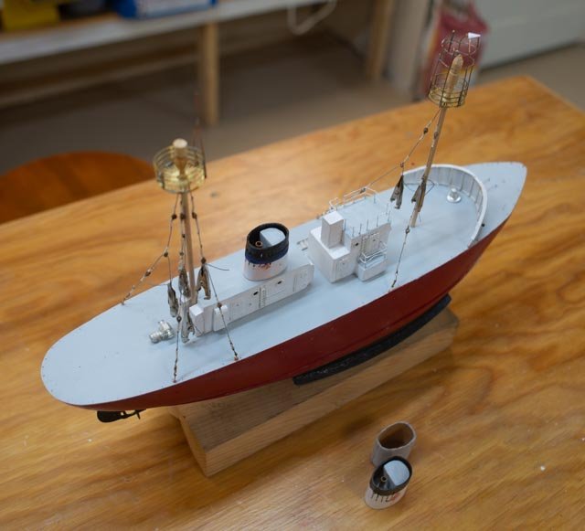
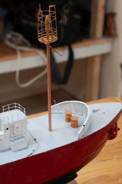
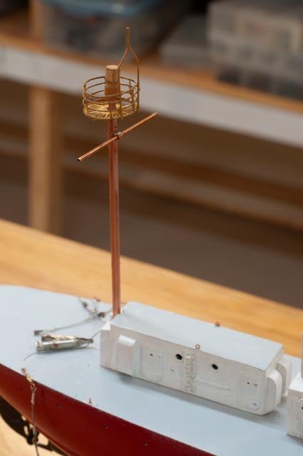
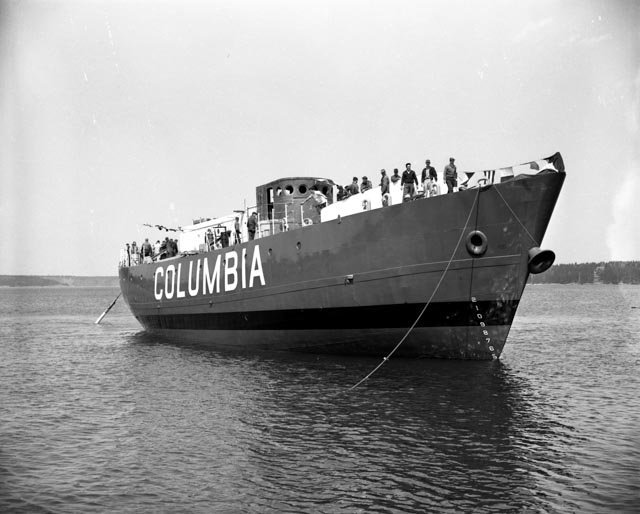
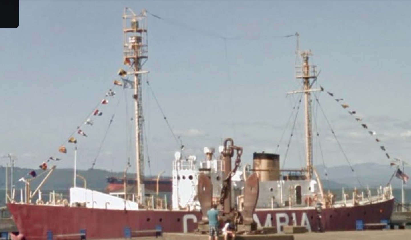
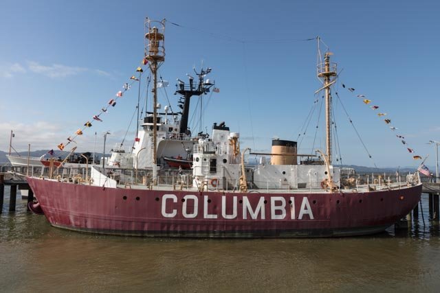
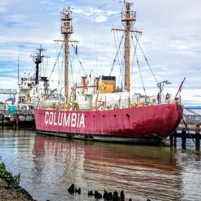
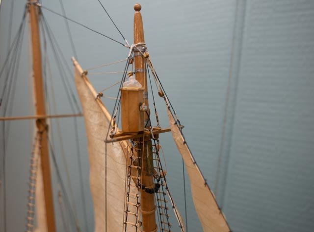
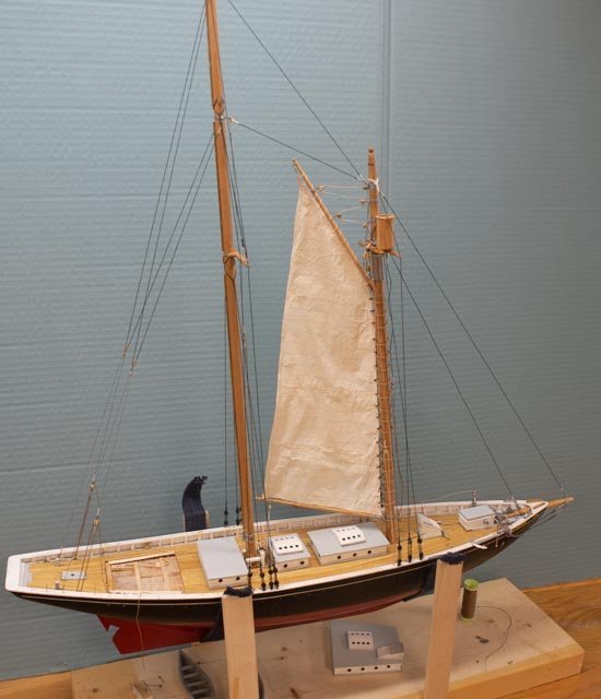
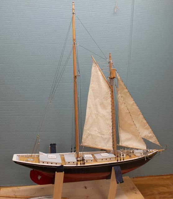
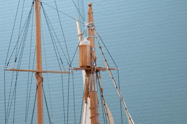
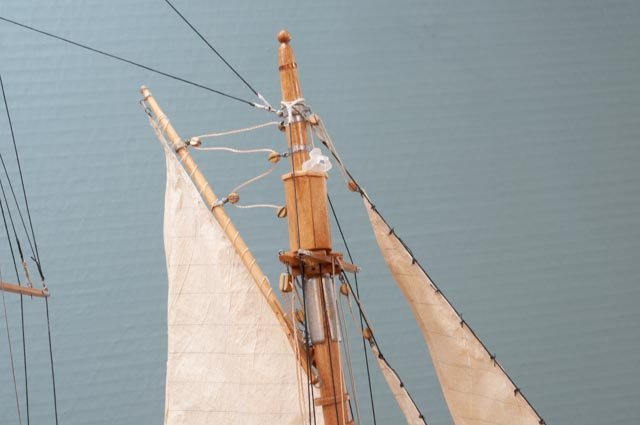
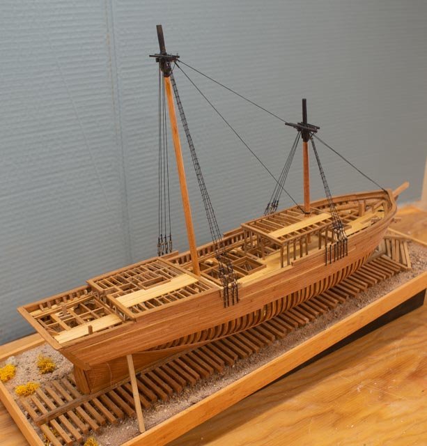
Post 5 Rough work to get through planning and into production for masts, rigging and the stack[ funnel]. Unlike many of the modelers on this forum I am a neophyte in most of our tasks. Soldering is one of them. I will share my struggle and persevere as to do the metal work at the top of the steel mast for me is a chore. Making the mast from a dowel allows drilling a few holes and things, but platforms? Also, the yards are clearly hollow pipes in the photos. There are many photographs to follow, so here we go… I hope I can pull it off. Mast lights and platform 1 here is a photo of the top of the foremast from Columbia. 2 here is a photo of the top of the main mast also from Columbia. 3 here is the first attempt to take the components from the Nantucket kit and apply them. Our mast is I take from drawings is 1/8” vs Nantucket 3/16”. A hidden washer is glued to the dowel to hold up the brass platform….I hope. I soldered the handrails and added the radio mast in copper. I find using Tix solder and normal paste flux works for me though it’s a bit crude. The lights are wood , shaped on a lathe, and I used the mill to drill a 1/8” hole so it can rest on the top of the mast. I hope paint does the trick. I am not ready to attach all the rails at this point. I may want to a paint first and I may change the mast to copper tube. I am still thinking about itat this point. 4. vhere is a rough foremast frame loosely resting on the top of the mast. I need to add a plate for the little triangle holding the aircraft warning light and some form of decking for the upper platform. It is a short mast too for the radio aerial. Rigging 5 here in a photo of Columbia we see the size for turnbuckles. They are roughly 4 feet and open. The connection to the deck is a compilation of plates and shackles. 2 of them are smaller on top of the aft deck house. For now, I will attach to eye. I will try to cover that with a tiny plate later. 6 here are the standard cross connection for short sections of shroud. I have laid out in an attempt to replicate their locations. 7 here I plumbed up the main mast and its platform and soldered it in place. I tried that combo solder paste but got nowhere. Doing the rigging is fun. I am using 2.5mm bullseyes, grey thread to replicate the steel cable in the photos and white tread to replicate the white tape in the photos. Stack Based on advice from a friendly guild member, I ordered a bunch of styrene including sheets. 8. I cut a styrene strip, and after soaking it in boiling water I clamped it around a plug. 9 after a short while I took it and welded it to itself as I rewrapped it around the plug for two layers. I then trimmed it back to size and laid out the slots. Then using a drill, knives and mini files eventually got 10 slots in. 10 In this progress view, you can see the first styrene stack on the table. It was too big, so the second one is now sitting in place partially painted. 11 I was unsatisfied with the wood dowel masts and decided that to replicate steel masts I should use copper. Here is the fore mast rebuilt. 12 here we have the new main mast. The paint for masts and deck furniture just came in from Bluejacket, so that work comes next. All for now


-
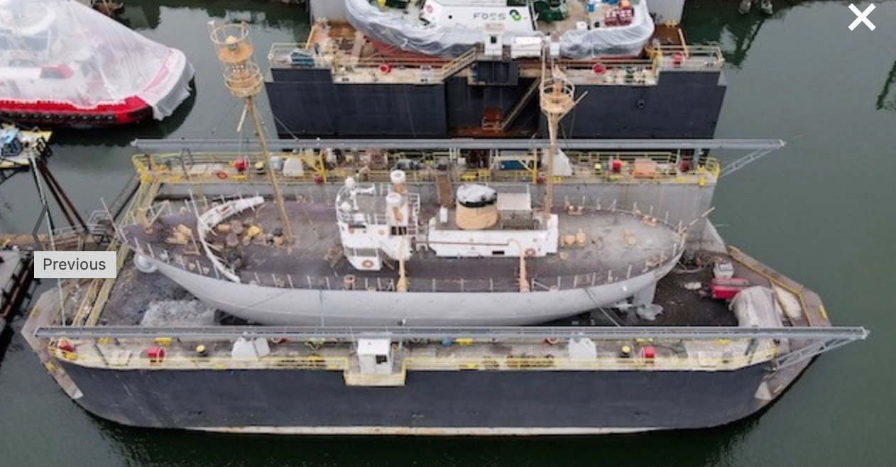
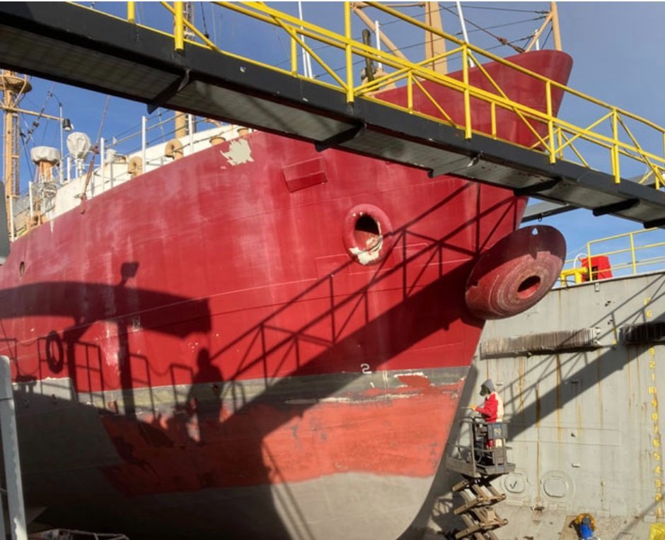
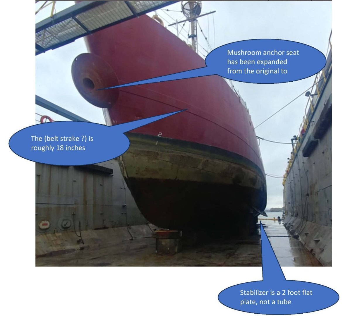
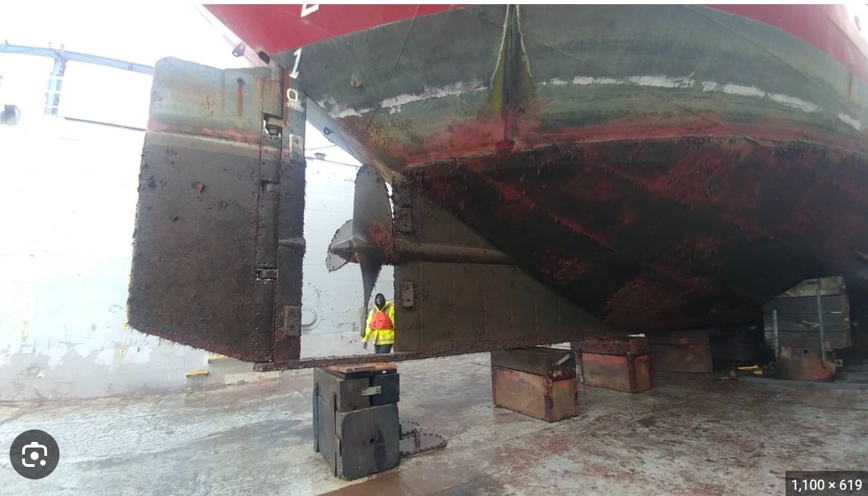
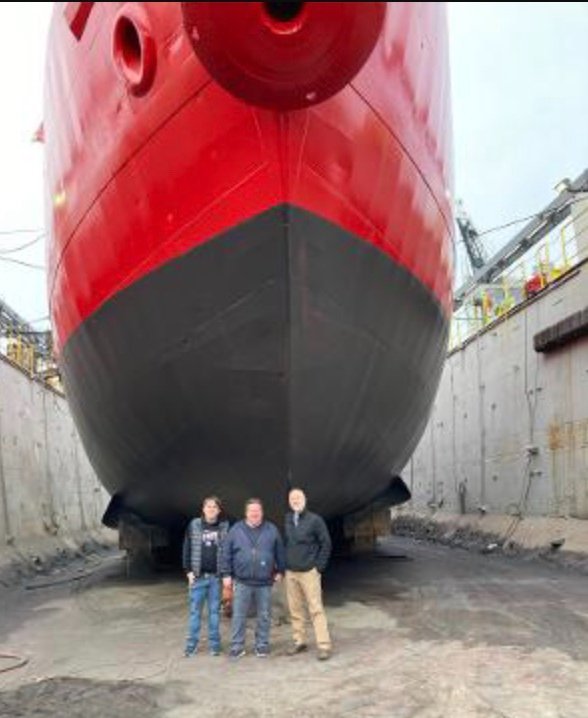
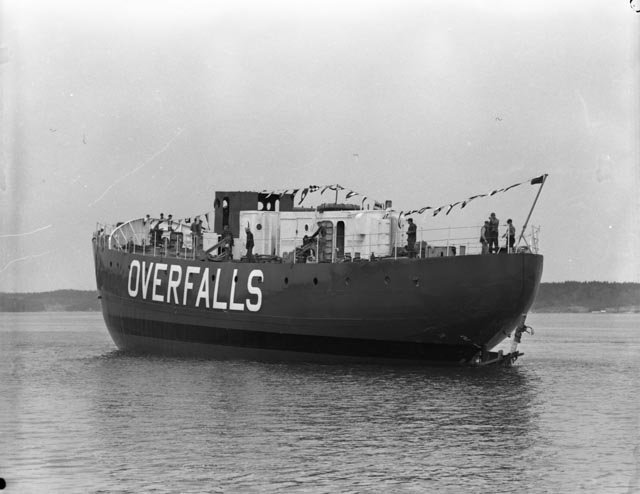
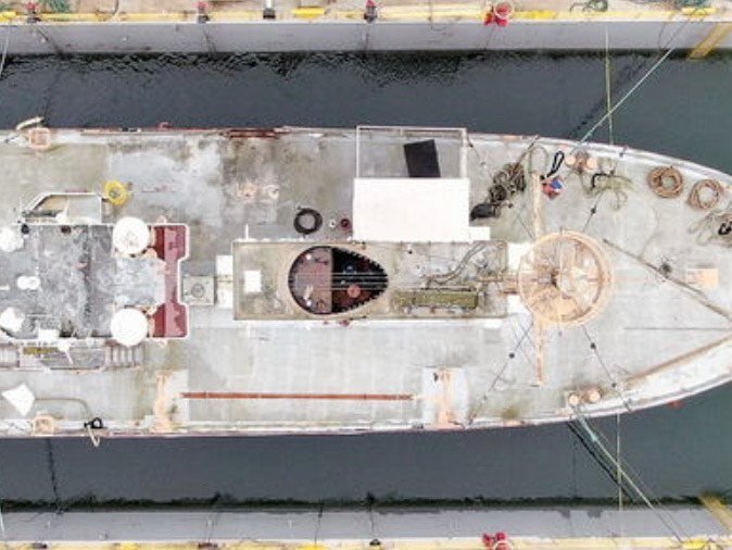
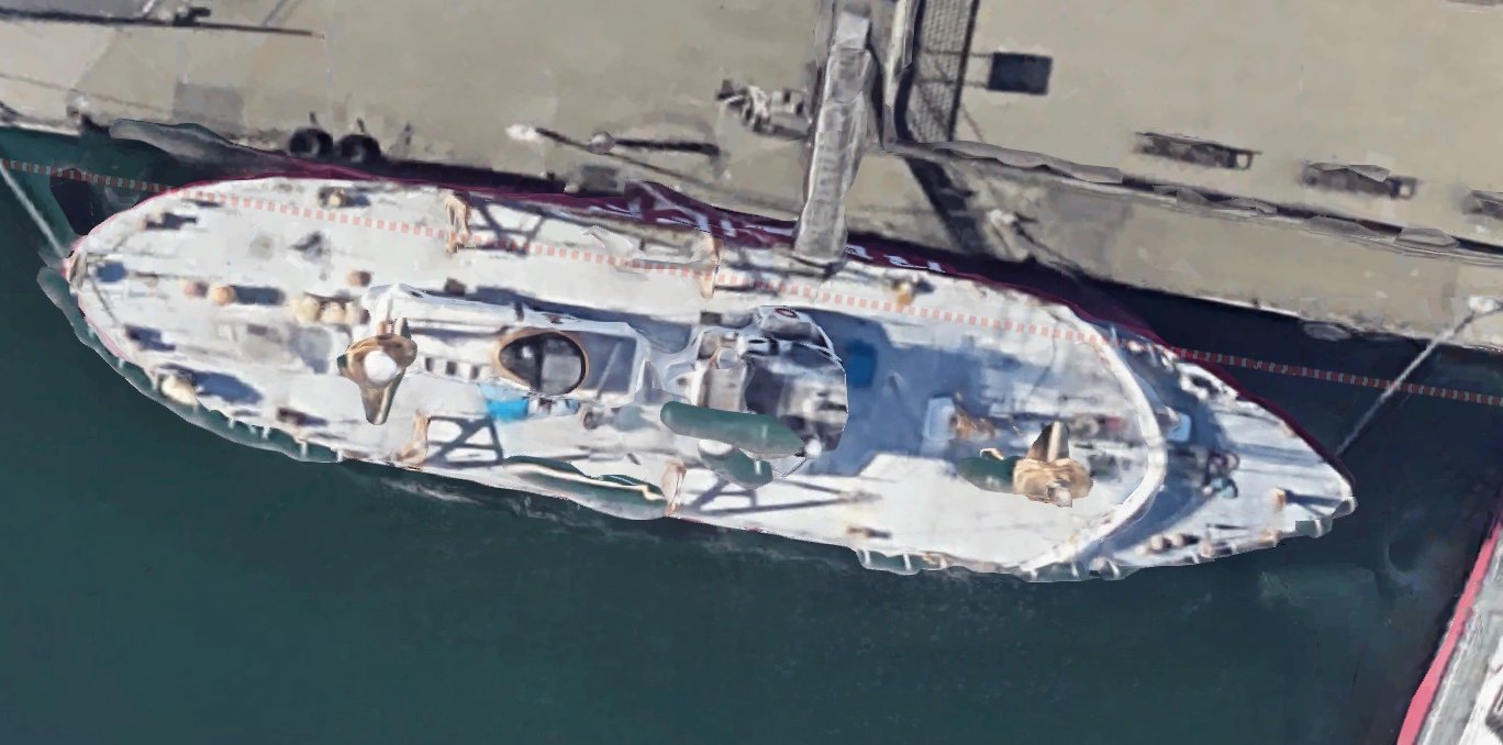
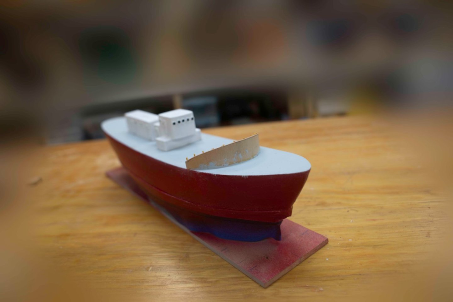
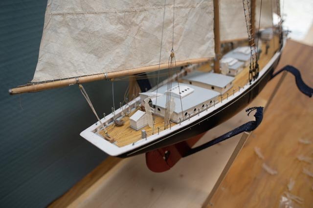
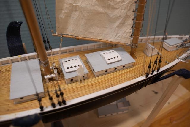
4 figure out the bottom I found some great sources through my online research with the photo history of the refurbishing of WAL 604 Columbia. Thanks to them I was able to review a few of these shots before cleaning u the hull. I am not perfect but tried to respect what I found. I am also doing a deep dive study of the Rice Brothers yard and have nearly 68 out of more than 400 images relating to the 4 Light ships. I will put together some postings of these as they are fun and original documents. WAL 604 and 605 were virtually identical and built together, so I have used images interchangeably. For hull completion, I share the following. The first five from the Columbia restoration website 1. overhead shot of Columbia in the floating drydock. 2. the bow sections giving good sense where to place the anchor hawes pipe. 3. in this view I was able to see that the stabilizer on the ides are indeed plated that project out and down a but. They seem to be about 2 feet. Also, there is no doubt about the bottom color. You will see my doubt as to 1951 bottom painting below. 4. This view shows the shape of the stern coming to a point down to the extension with the prop. It is quite thin. I chose the make it as thin as the prop hub, so it could remain part of the solid hull. If building this hull with bulkheads of frames and running the keels etc. it would be easier to honor this thin shape with eh shaft pipe visible. also note the square rudder. an oops is coming below. 5. In this view, we see prefect scale figures. We also see [confirmed in another shot I will include later] that the the mushroom anchor in place and painted like the hull, I plan the same. Next, we have some photos I recently scanned for the Boothbay Region Historical Society. I include thumbnails here but enjoy the high resolution in our study. 6. Here is Columbia just after her launch in 1950 not the interesting Black stripe. blowing up the image in sees it is 3 feet top to bottom. Also, the “belt strake” or perhaps the ‘wale’ is clearly placed. It looks to be 18 inches which is what a did. 7. Here is Overfalls after her launch just weeks behind Columbia. Progress. The hull is sort of done. Someone showed me how to play with my photos so I tried this technique. great for once and awhile; I won’t do it a lot, but occasionally it is fun. 8. Looking aft: I have thinned up the cheeks to meet the plan for the smaller vessel. 9. Looking forward: I hope the stern respects the intent of the sharp lines I am also using the kit Nantucket rudder which is a little bit tall and not square shaped. I figure saying that gets me through any test. Up next, I am working on the masts and rigging.
-
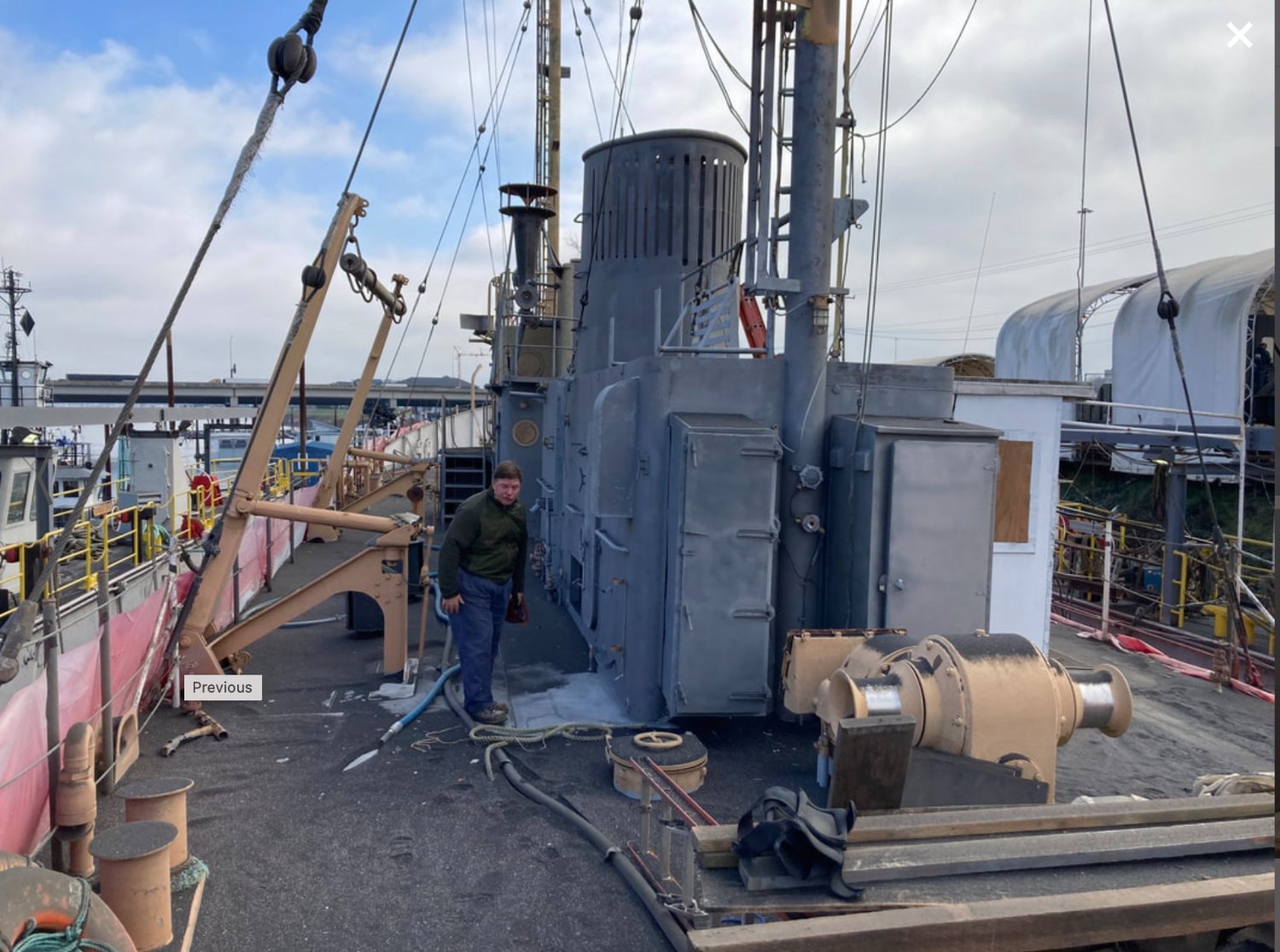
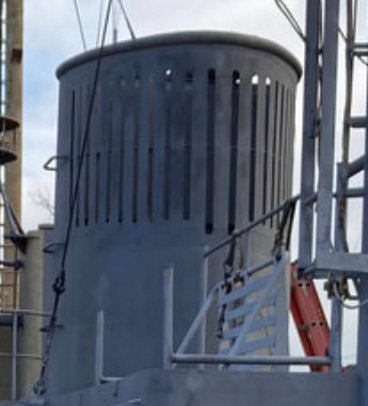
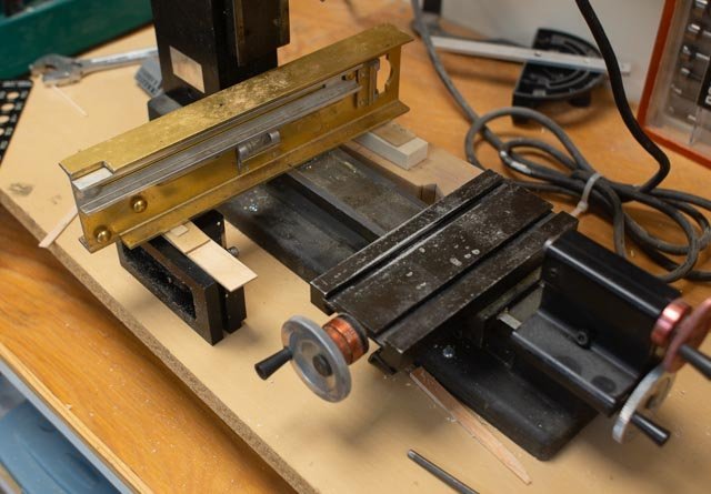
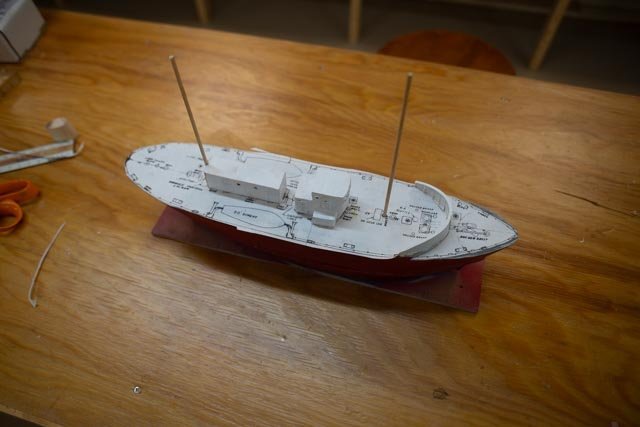
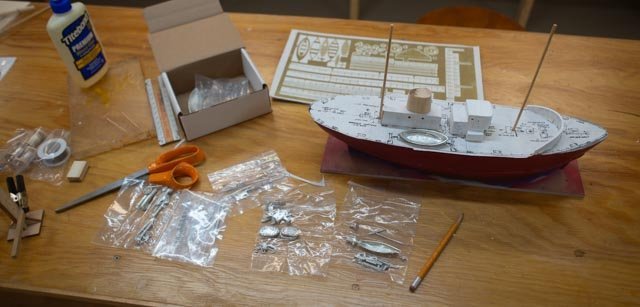
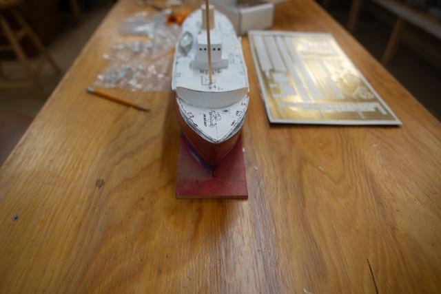
3 plan out the preliminary deck work. This phase of the work will combine the deck plan and photos to figure out what to build. The following photos illustrate this process. The first sub project will be the stack [ funnel]. so let's look at some photos to figure out what we want to build. 1 here is one of many typical photos to pick out details like bitts and chocks and rails and things to compare with the plan. From a far, all we see is a painted teardrop funnel...should be easy.....I don't think so... The stack is a project under itself. I suppose I could simply make a block and paint it, but trying to replicate it will be a challenge and learning process for me. 2 The Blow up comes from the high definition photo at library of congress. One can see through the slots a rusty stack inside. 3 this general deck view came from the WAL 604 Columbia refurbishment web site. It shows lots of information including the stack 4 this blow up of the former photo shows the clear challenge. How does one make all those slots? Then what does it look like from the top, since there is obviously daylight coming through the slots? 5. After several emails within our Downeast Shipmodelers Guild , look at this gem of a photo I received last week. Thank you, Jerome! Just like I thought, the forward half is full of other stuff, a ladder, a platform, goosenecks, even radar etc. The back half is a big funnel with a centered stack. This is my first model without sails, so I have a lot to learn. My Schooner experience is limited to a Charlie Noble [stack] or the Donkey engine exhaust pipes. The next sub project will be the two masts. One simple thing is there is no rake to worry about, they are to be plumb. 6 here I made a level base and set the hull in the mill to get plumb mast holes. 7 here we have the deck plan cut out and set in place and the two masts inserted. 8 here I tried to inventory the kit parts to see what I might be able to use and what I need t add. 9 In this view we find the bow of the hull is too full in the cheeks. The pencil marks on deck shows the part that needs to come off. The next two photo came from google maps ; not much detail but fun. I found it interesting that the overhead scale for Astoria, Oregon is limited by about half from that of Oakland, CA.. That is why I chose the ground view for Oregon. 10, All for now


-
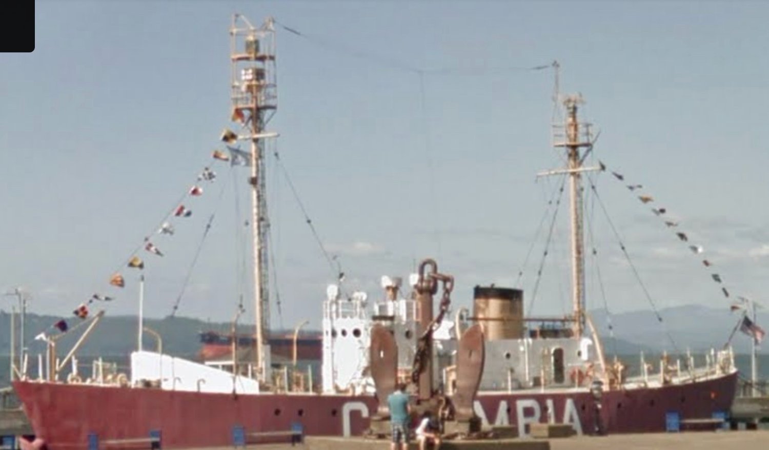
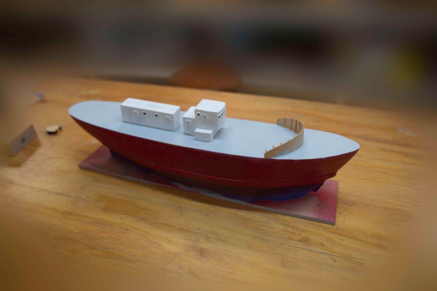
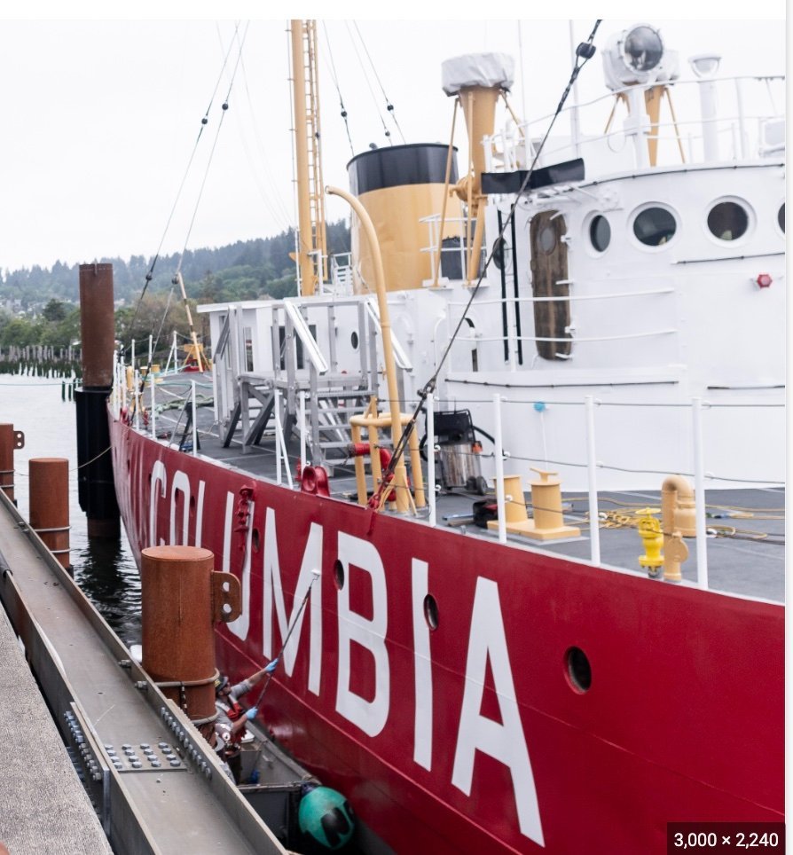
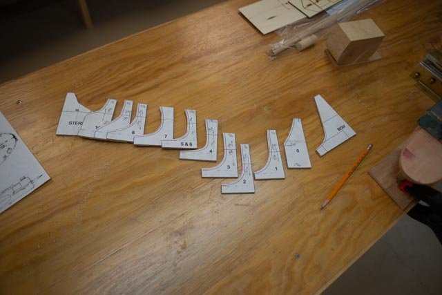
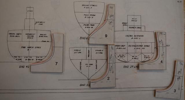
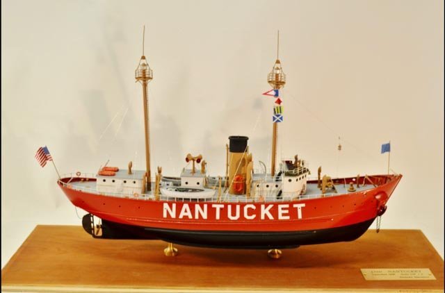
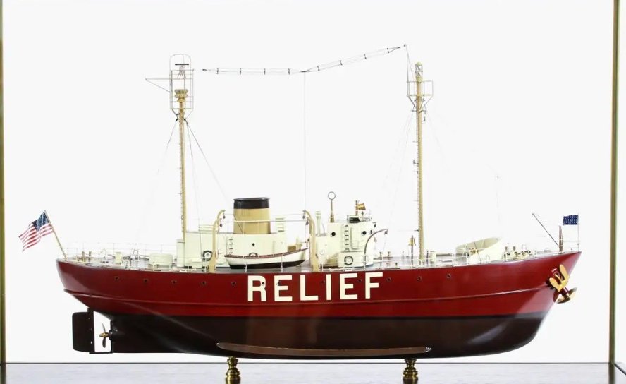
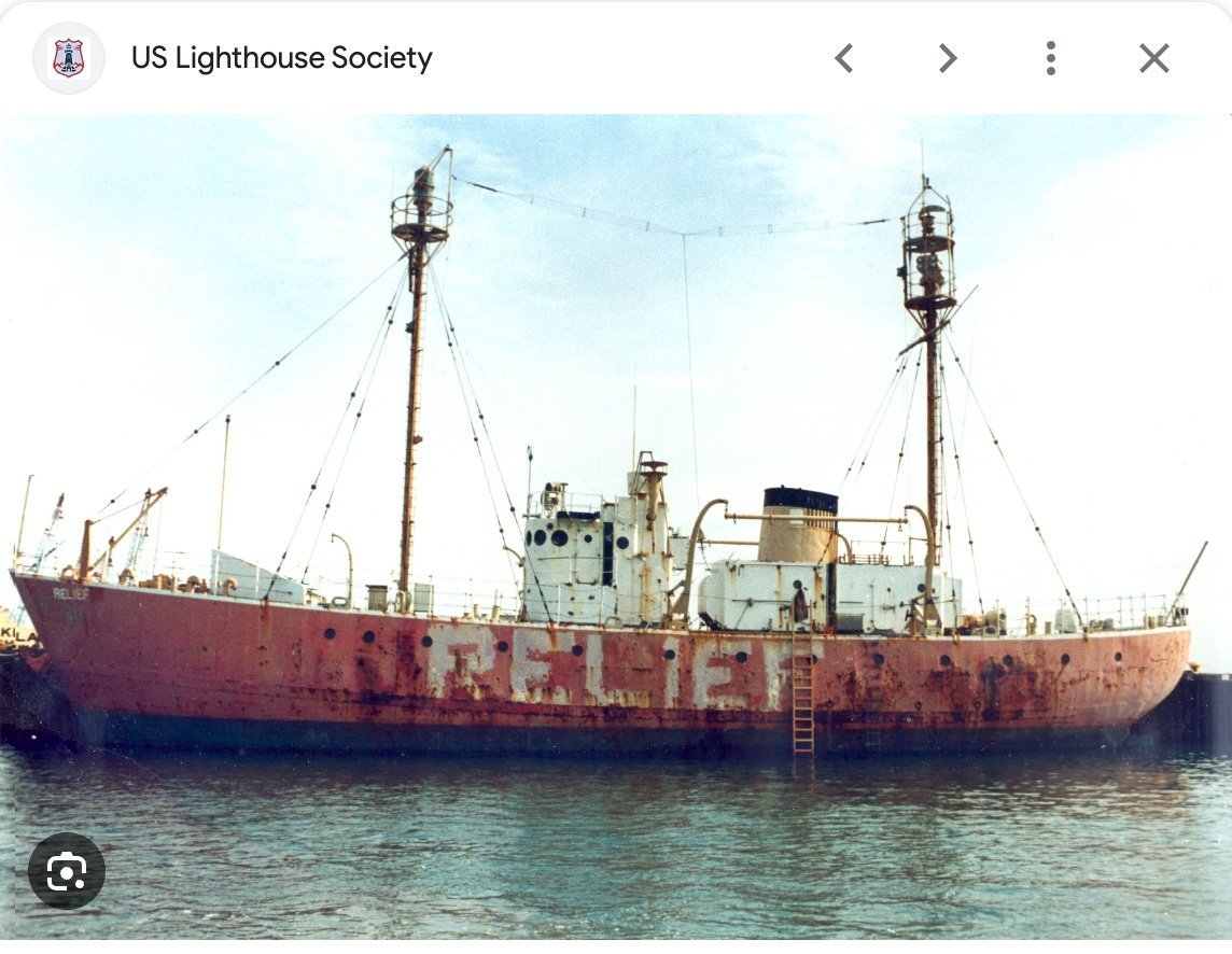
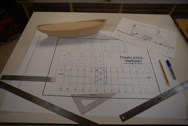
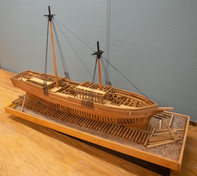
02 rough shaping the hull First up I have the outline and template plan from the Nantucket kit. The beam on Nantucket is 32 feet and the Overfalls is 30 feet. That difference means in theory I would remove 1/8 inch from both sides. I wish it were that easy. 1 Here we see all the Nantucket kit hull templates cut out with a nominal 1/8 + left on the inside marked in red. 2 In this view we see the Nantucket templates that go close to where the Overalls’ bulkheads are shown. I am not sure if tumble home is the right term here, but the Nantucket hull needs flattening to some extent to achieve the straighter sides of the smaller vessel. The conclusion is that I will not be using these templates. Second up, let’s look at some photos and see basic differences in broadside profiles. 3. here we see a model of Nantucket. Swooping bullworks at both ends, a very high bow etc. 4 here we see a model of WAL 605 Overfalls, Blunts Reef and Relief. Notice the Low bow no bulkworks etc. This model someone made in California and has it online for sale. They show a few things that help below the waterline. They show their interpretation for the appendage clearly and I think even painted it differently from the hull. Now that I have two sets of plans, they both show it. I was wondering if it’s active or just a passive element. Fortunately I have found a photo just yesterday of it I will share later. 5 here we see a broadside of WAL 604 Columbia ,built side by side and launched only weeks earlier than Overfalls. There are no bullworks other than the high breakwater crossing the deck just forward of the mast. The deck also seems much flatter. This very high-resolution photo from Library of Congress is great for my looking at the deck furnishing. 6 here is a view from the stern quarter and we see the slight rise at the stern and relatively straight sides. There is a slight bulge. the "belt strake" or whatever it is called is quite clear here. 7 here we see bow details this view is important to understand the mooring bow hawse pipe arrangement as well as the straighter sides. A small point but a Navy anchor is fitted to starboard on the Overfalls and apparently not on Nantucket. Looking at the two issues above, I have concluded getting the broadside profile right is very important and removing some of the roundness should be enough to get me into the area that replicates the hull. 8 Finally here is a photo I love. It shows Overfalls after her California assignments Blunt Reef and Relief and ready for restoration. Progress I have taken the next steps and adjusted and sanded the hull. [ not the bottom yet] I have kept the hull glued to the board so I can keep measuring up for the shear line and eventually the water line. I added the Belt strake [ or whatever it’s called], figured out the waterline, shaped the deck and added the break water, splash plate, again or whatever it is called, that is unique to this design. I also made roughed out the two deck houses. From here on most of what I do will be based on the photos of the two restored vessels in Oakland and Astoria museums. 9-11 Here are three shots catching up with the build.


-
Mike thanks for the link. yes quite a story of the demise of the 1934 lightship Nantucket. In other links one can find that the search for the replacement found the large 1000 ton and 148 feet long vessel that served until the end of the lightship station at Nantucket. I include for your and others enjoyment a nice article that summarises the lightships of Boothbay, the them of my build. That means the Lightships of the Rice brothers to be specific. https://maineboats.com/print/issue-165/rice-brothers’ cheers
-
Thanks Mike I look forward to visiting Lewes. It is only a couple hours from my daughter's home.
-
Thanks Roger i went through the Journal indexes and found the fun article by Chapelle...models that should be built. He mentioned lightships, so that mandate was good. There are several references in index 41-50 and I will definitely check them out and share what I find. I am also into some new books, part of the fun, and I will summarize those findings as well. Thanks for looking in.
-
thanks Nic I am making my list for some more parts. I need to get a better idea and inventory from the photos I have, so I then identify what I have and what I might need more
-
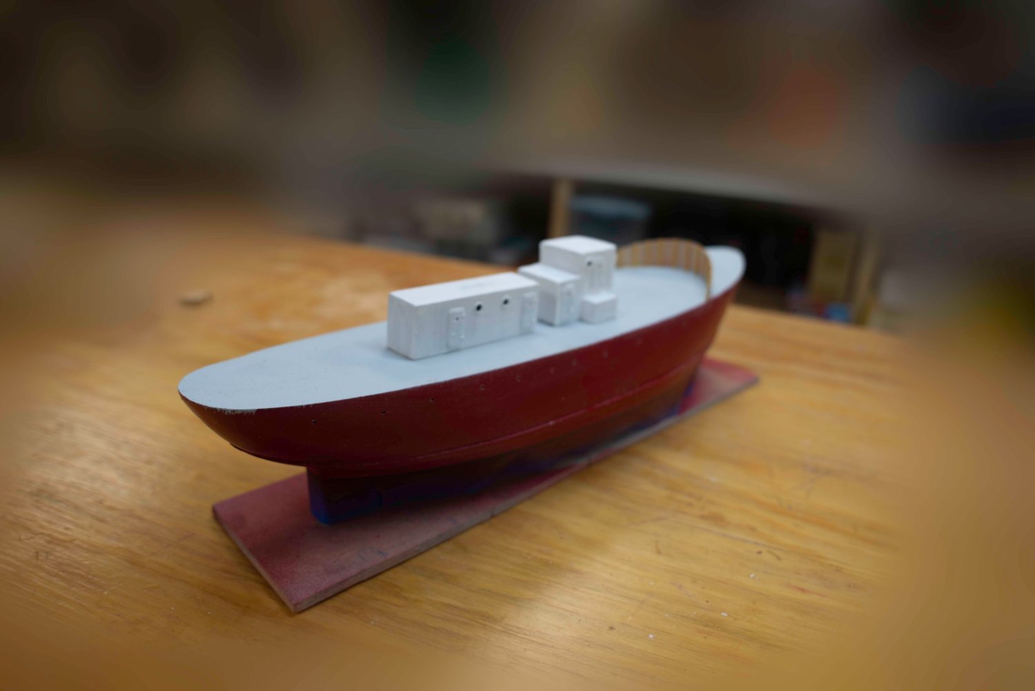
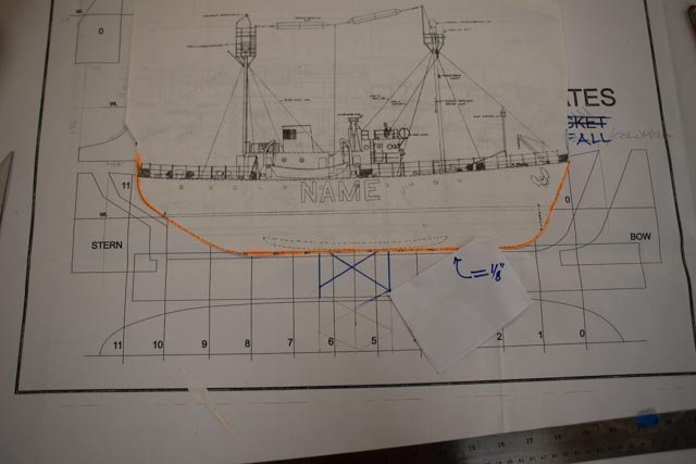
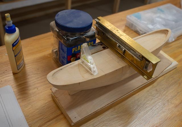
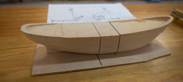
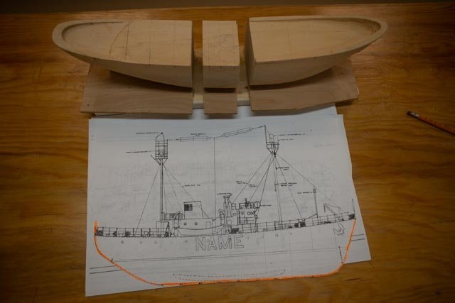
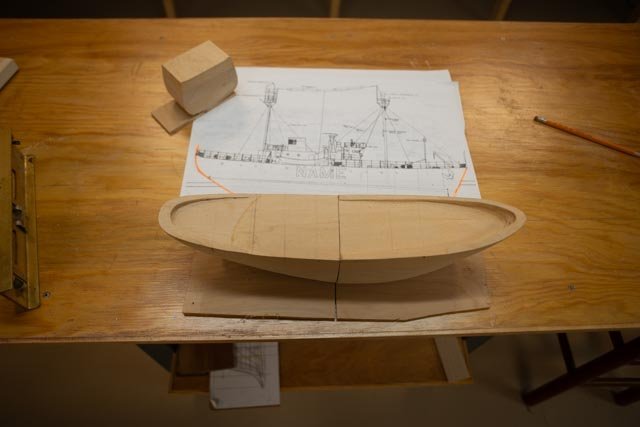
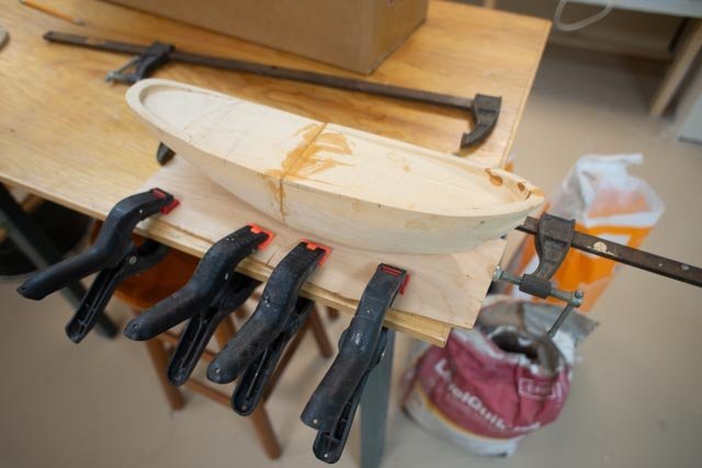
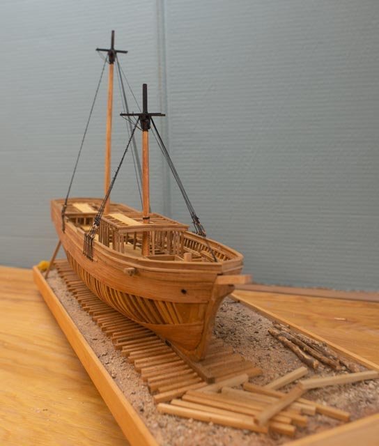
Building log for the Lightship Overfalls at 1:96 by Jond. LSO 01. the beginning This new project has taken some time to figure out. Last year I completed an overview of the history of Boothbay shipyards 1800 up through 1920. I built a three masted schooner to be a center piece of that presentation. I then built two brigs to fill in more of the past. This year I have begun to dig into the next era of Boothbay shipbuilding beginning roughly 1920. I also want to move into the world of steel ship building. Wow there is so much to learn and each week I find even more avenues to follow. To reel in the expanding study and to focus on what will be part 1 of what now will be at least three builds, I chose a fun topic. Lightships of Boothbay. There were four of them. First up I would like to list the 4 Lightships built here in East Boothbay at the Rice Brother’s yard. Parallel to this log is my research of the evolution from wood schooners into steel ship fabrication that started here about 1915. I chose a lightship as a model because I just learned that three Lightships of the 4 built right here are now in prominent US Museums. One is in Delaware, so a fall road trip is already planned. The four lightships built here include: 1. LV 99. Poe, a reef off Sheboygan, Wisconsin, the work was started in 1916, but alas, the hull was burned in a yard fire 1917. The Lightship was rebuilt and launched in 1921. She was sold out of service in 1955. 2. LV 118 Cornfield, a reef in Conn, was built in 1938. She served 20 years there and then as LV Cross Rip near Martha’s Vineyard then LV Boston through 1972. Since then, she has been docked in a museum in Lewes, Delaware. 3. WAL 604 Columbia, Mouth of the river in Oregon, was built in 1950. Now she is docked in the museum at Astoria, Oregon 4. WAL 605 Overfalls, the entrance of Delaware River built 1950.After decommissioning, she was sent to Blunt Reef in California and then became the west Coast Relief. She is now at the museum in Oakland, California Secondly, let’s start at the beginning of Rice brothers and their Lightships. Rice Brothers started in East Boothbay in the 1892. Their growth was substantial and lasting. After they finished in 1955 several owners worked in the yard and then since 1985, it has become the major establishment named Washburn and Doughty. For my immediate study, the steel hull 98-foot Lightship built in 1916 has few documents on its detail. I will continue to research to see if I can create better images of it, but not a built. Several steel draggers were built then and steel aluminum work as well as an impressive wooden fleet emerged. I have just digitized over 400 images of their history. I love the stories and history of the second lightship, built in 1938 at 114 feet. Its history led through Connecticut then Martha's Vineyard and Boston eventually to its home starting in 1973 at Lewes, Delaware. To confuse some of us, she was renamed Overfalls by the park in memory of the light ship near there. Rice Brothers also built the real Overfalls in 1950, but she went to the west coast after closing the Delaware station. I really wanted to build smaller 1938 one but again lacking in drawings I hesitated. Number 3 and 4: we have the best possibility to reasonably create a model based on documents. Two vessels-built weeks apart and launched in 1950, were the lightships Columbia and Overfalls. They were virtually identical at launch. The Columbia naturally went to Oregon, and she rests today in Astoria. Finally, we have my target. Wal 605 was launched as the Overfalls. After decommissioning in Delaware, she went to be Blunt Reef in California. She then became the west coast Relief vessel. She now rests in Oakland California with the name Relief painted on her sides, however I will name her Overfalls as that is how she left the East Boothbay yard. Sorry for confusion, but I didn’t do it. I believe for me it is a good transition vessel. I know so little about modeling anything like this. That means more books and more fun. As to the modeling it takes me into work where I also have little experience. The on deck fitting out of a vessel of this era makes tying knots and silk span sails a useless skill set. The build: what to do and how. This build is based on taking the Bluejacket Kit for the lightship Nantucket and changing it to another Lightship 20 feet shorter with a different on deck configuration that was built 14 years later. Unfortunately, as I have already progressed a little, I have found much of the kit material will simply go unused. Never mind there is so much new stuff and am grateful for what is included or available, and I will make up a list of what more I need due to the different configuration. Example I need another exterior doors, a different motorboat, and a navy anchor. My first need is plans. The lightship kit Nantucket comes with great plans. Unfortunately, it was 148 feet and over 1000 tons. I have read that by 1950 the service had settled on a standard design of 128 feet and somewhere around 600 tons. The lightship Nantucket was apparently a beast due to its location. I found a small pdf set of plans online of Relief and now thanks to Don at Taubman plans I have a complete set even with lines for the LV612 San Francisco. That was another 128 ft standard coast guard design lightship that was built in Maryland in 1950. Both sets are the same, so they should be a match for here the same year. Starting out the hull using the Kit After a very brief consideration of scratch building a hull with at that time no proper line drawings, I called Nic at Bluejacket. They have a solid hull kit for the Nantucket lightship. That vessel is bigger but was built in the same era with many of the same things. We talked briefly about options in cutting down the hull to fit a smaller build, 1938 Cornfield. I had been trying to get back to this ship at only 114 feet and the kit would not work. I decided then the 1950 hulls at 128 feet is the way to go. I have a normal cut off saw and can take 20 feet [ 2.25 inch in scale] out of the middle of the hull and then make it work…..we’ll see! Nic said after listening to my plan that if I screwed up he could sell me a new hull.....😄 I think this kit will also help me get into more modern ships much more easily too. Many of those little pieces will be new to me and I surely need more experience at the 1:98 scale as well. My fingers don’t like it small but that is the way it goes. Hull early Progress: First up I have the outline and template plan from the kit. It is right on …18.5 inches = 148 feet. There are two stations, 5-6 that are the same, so I need to find the middle of them and cut back 10 feet in scale each way. 01 here we have the kit template plan. I have identified where to remove the 20 feet of hull amidship. I will do the lines separately before making the templates. 02 here I have cut out profile section of the 128-foot standard design I found on the internet. The highlight confirms that the draft difference is about a foot and the bow is not quite so high. It is not perfect but a way to get there. 03 I glued to hull to a plywood strip and made the deck level. This will sit in the cut off saw. 04 Here we are back from the garage shop with the center cut. 05 the center is now apart. 06. the hull is dry fit. 07. I chose to go get the Wes Systems epoxy to make this joint. I will need to sand 1/8 inch off the sides, so it needs to be a strong joint. next up fix the hull profile.....all for now
-
Andy and Craig thank you for your kind words. I was just with David yesterday as we recruited him to be grand Marshall for our classic boat and yacht club regatta boat parade next Sunday. I will pass on your hello. I did know he was out there in high school. He still skis. cheers
-
Thank you for your kind comments. I am off researching a new era of steel fabrication for my next venture. cheers
-
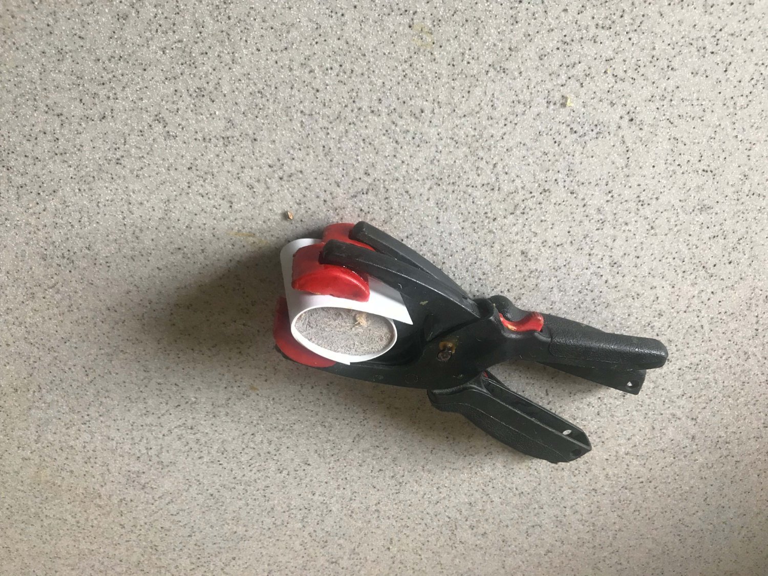
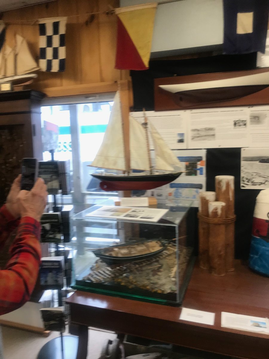
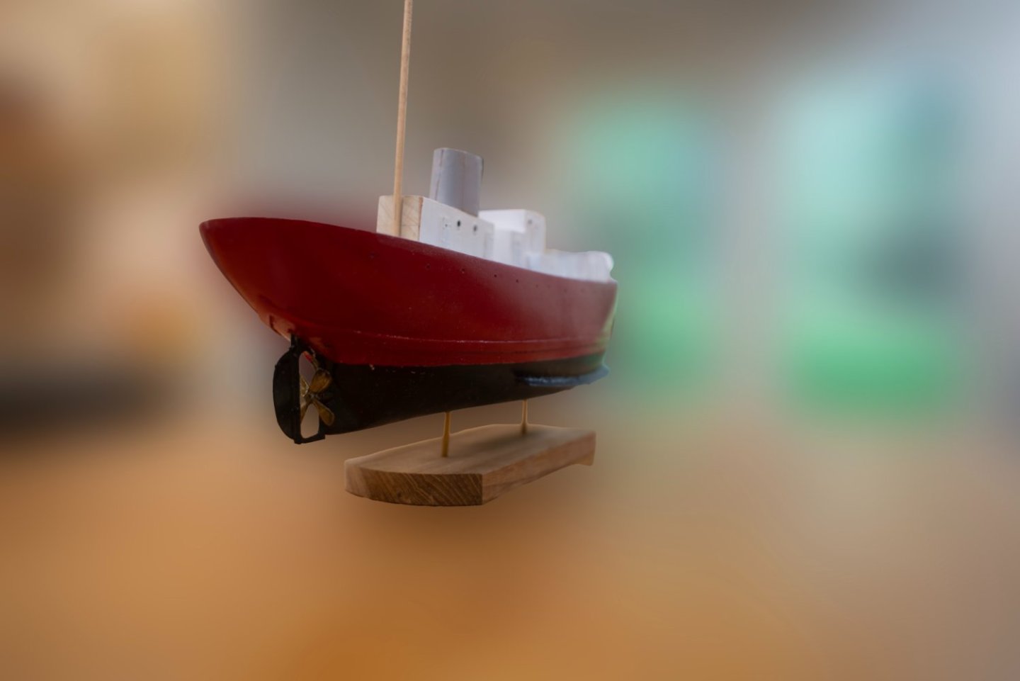
Wow. Thank you all for your kind comments. This was a fun build. The red sleeve and hand taking the photo in the museum store above was David Nutt son of the owner. He joined me that night in June to talk to a crowd and the crew of schooner Bowdoin as they left for Labrador. I put some pictures on my old log for that build log of them leaving. I am now getting into the next one. cheers
-
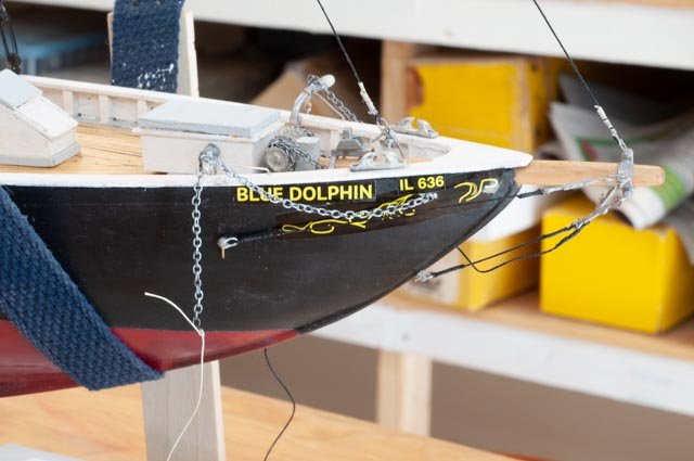
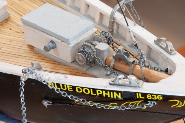
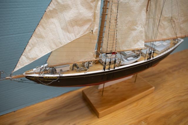
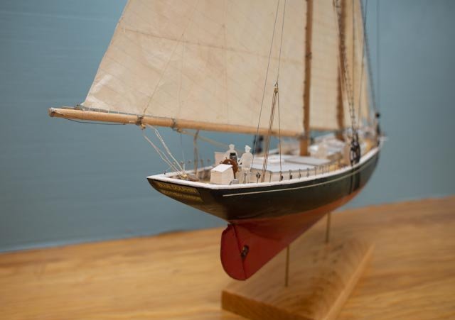
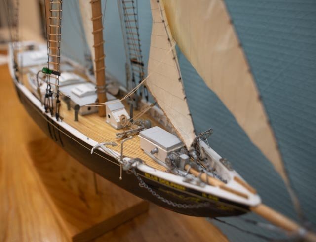
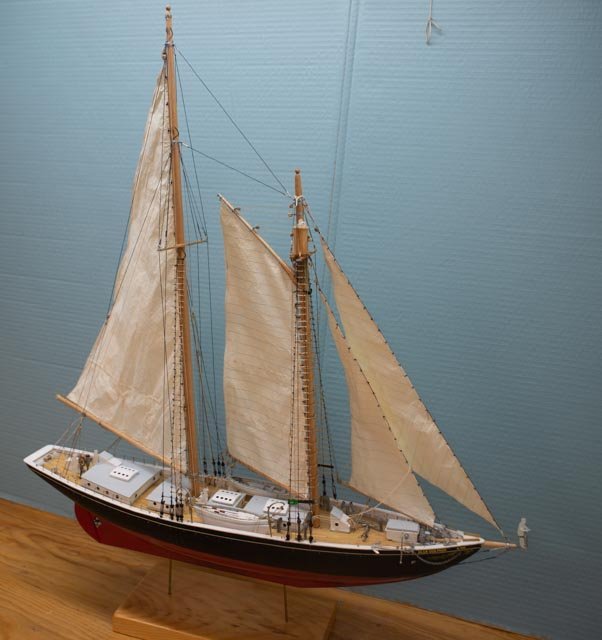
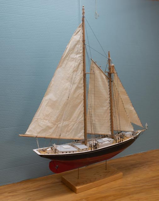
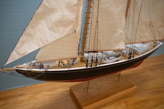
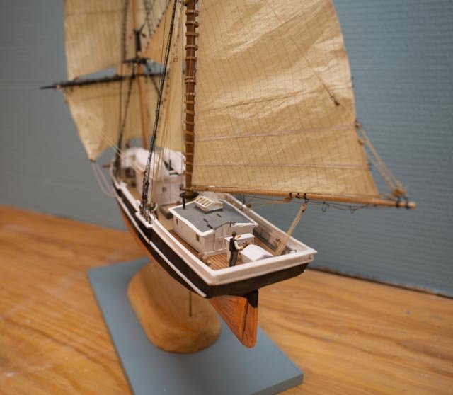
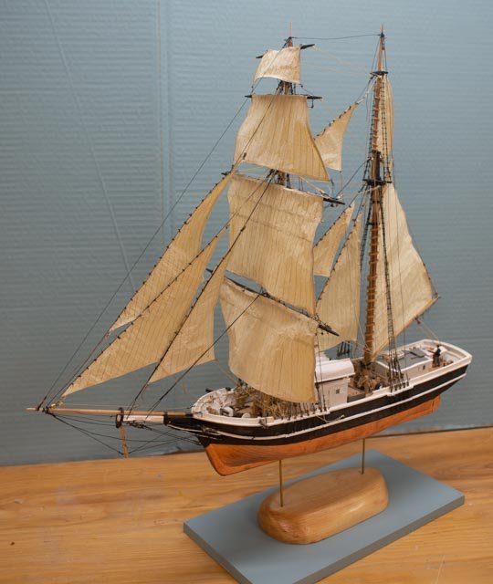
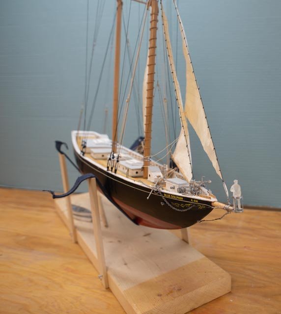
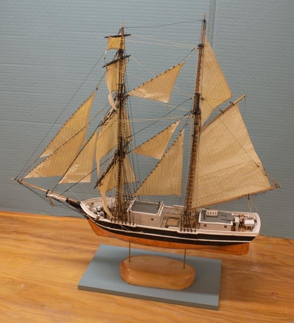
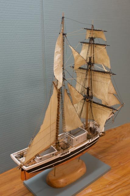
15 we are done We have taken her to the Museum store, given our first summer talk on the a Arctic sailing of the Schooners Bowdoin and Blue Dolphin, so it is time to close up the folder. I have collected a view of her in the museum.The nice guy that used to make us glass boxes is no more , so as light as the model is, we decided it could just rest on top of the 1824 Pinky Schooner which rests next to Diorama Bowdoin.in their boxes. here are several photos of the model before she went downtown

-
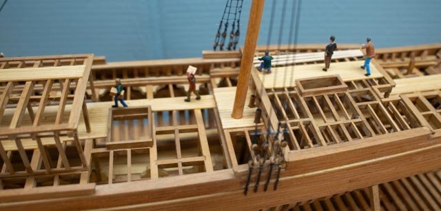
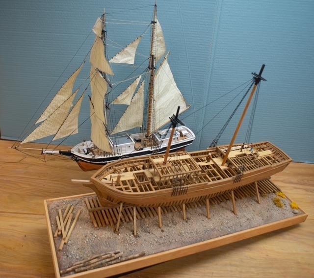
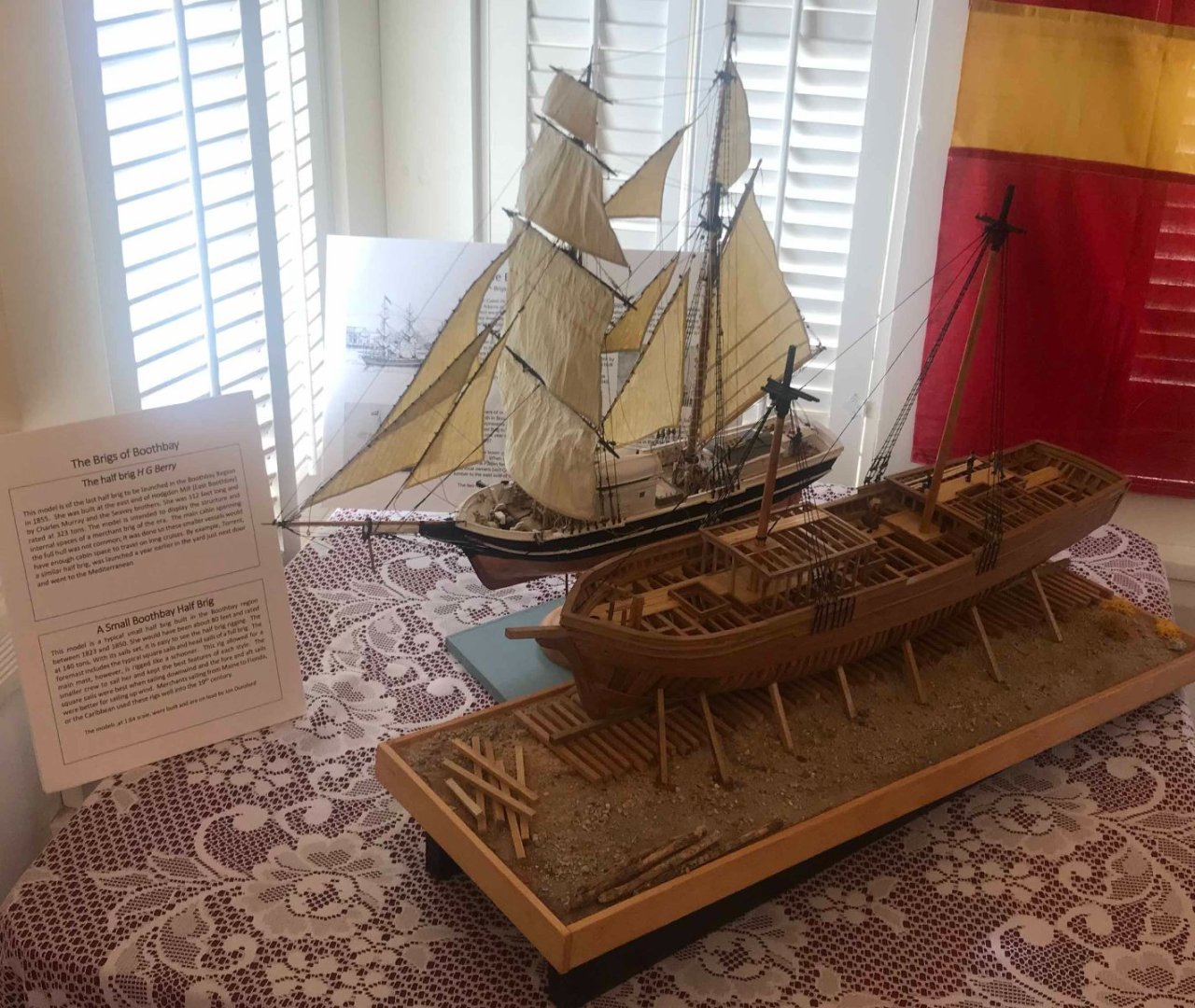
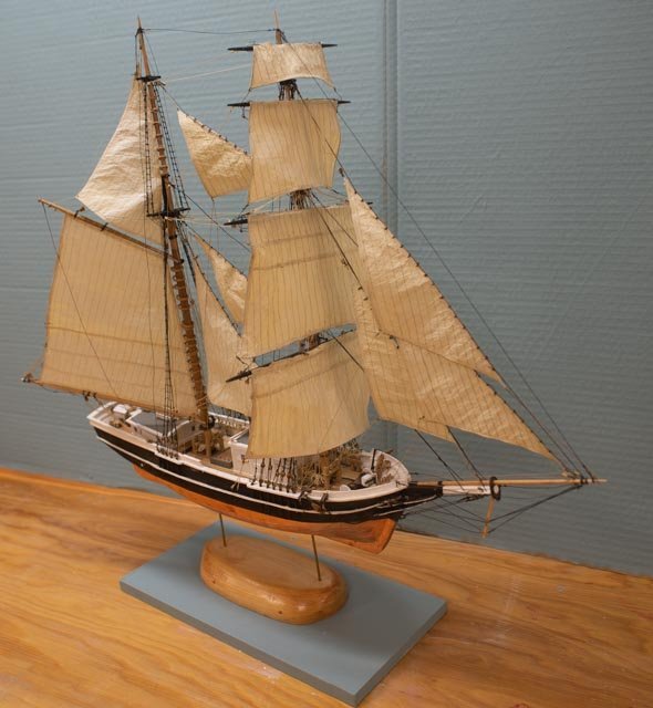
78. the final shots In this final posting we see the H B Berry completed with crew and the the two brigs together at home and downtown at the Boothbay Region Historical Society for the summer season. together
-
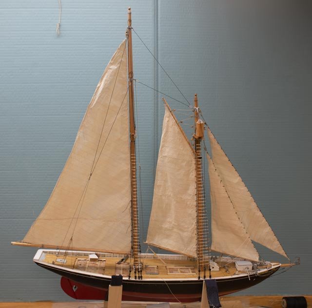
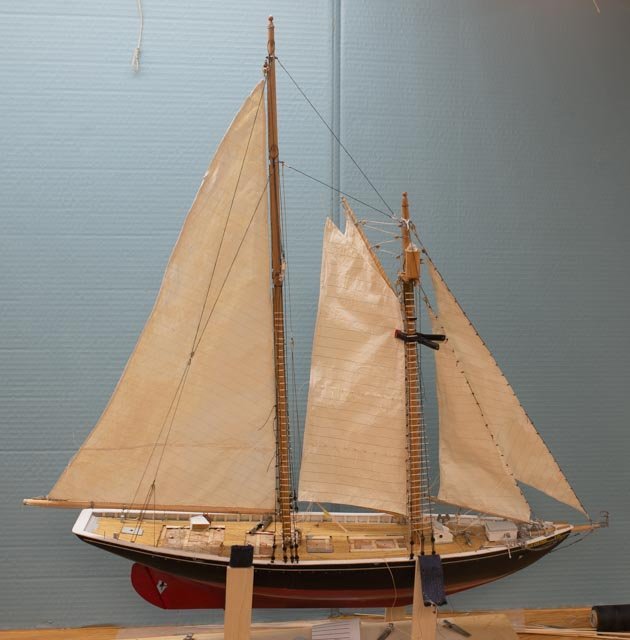
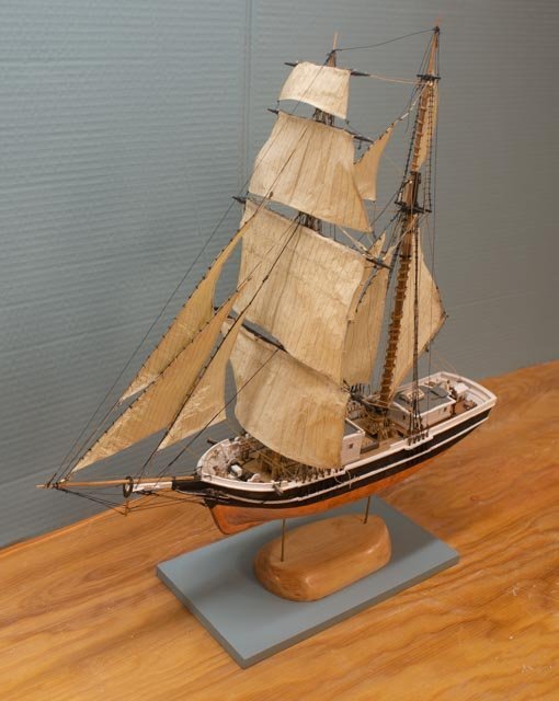
77 small sailing half brig is done Now that models are on display, my talk on their history is completed and the shop is cleaned up ready for the next venture, I want to close up this log with two postings. This one is the small sailing half brig. Here are several views of her just before she went downtown
-
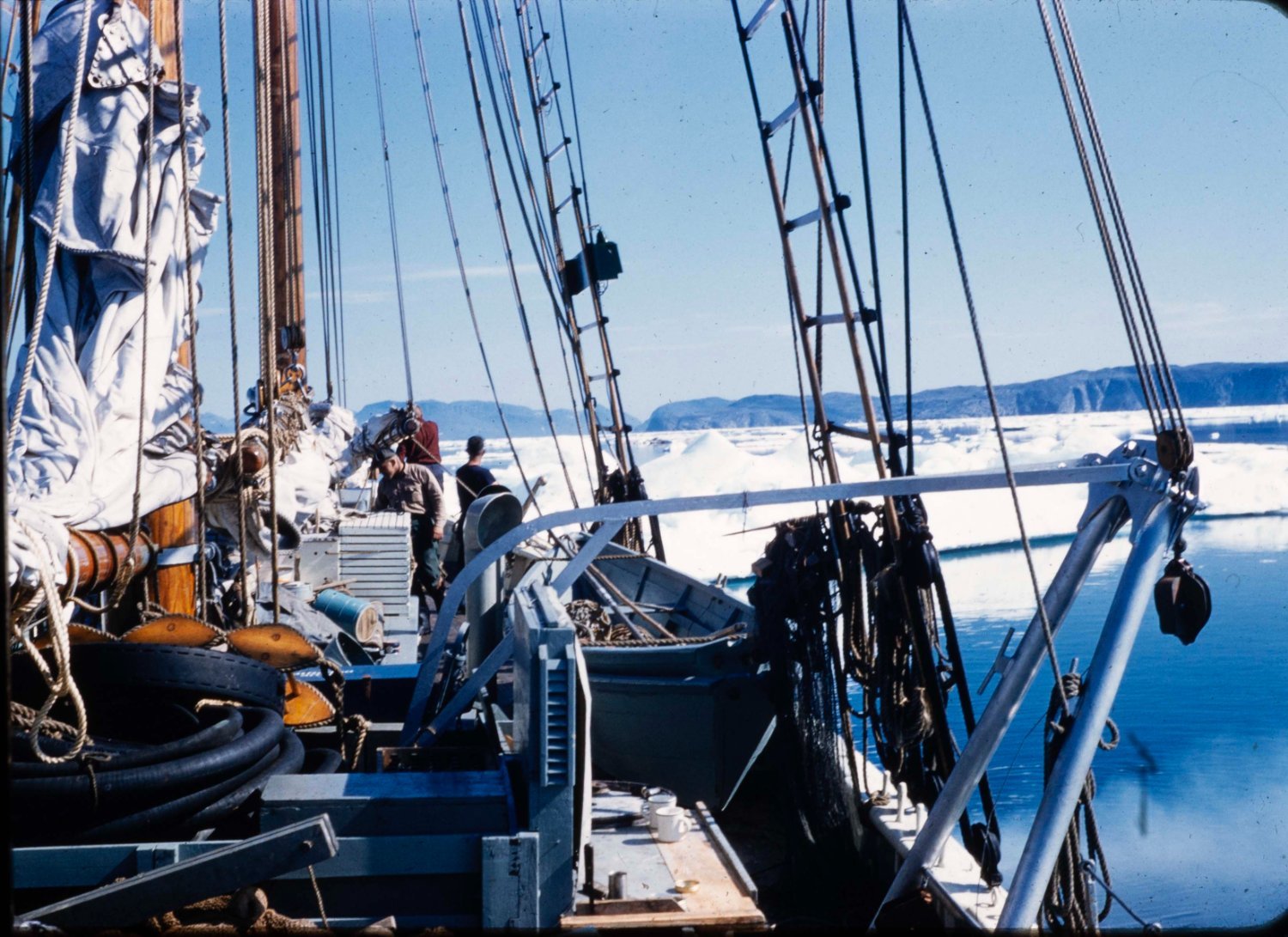
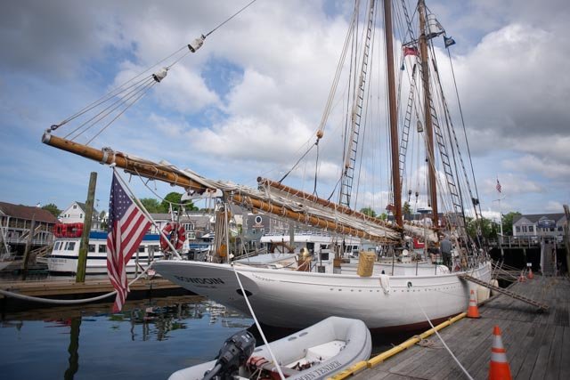
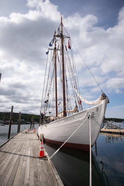
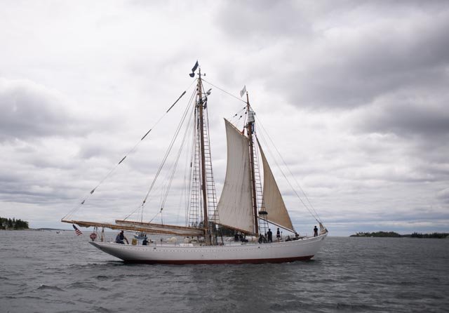
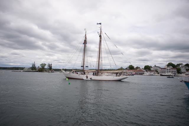
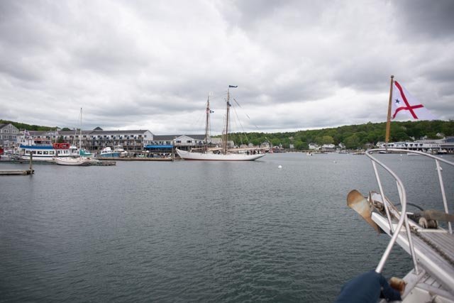
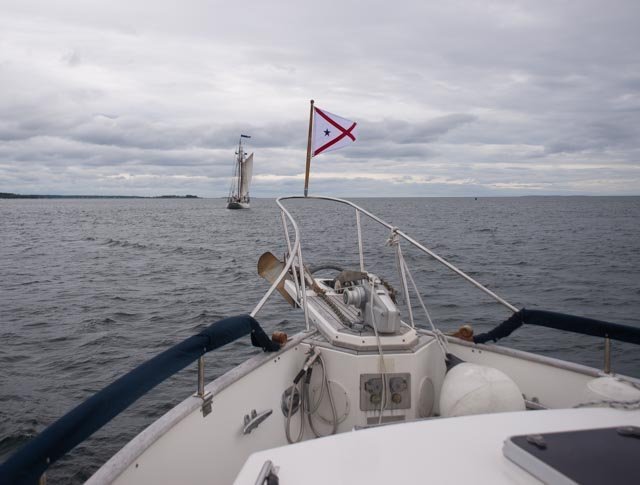
for all you schooner Bowdoin lovers out there in 1954 Bowdoin came to boothbay Harbor in June. The undersecretary of the US Navy and other brass came and promoted Donald MacMillan to admiral on the town dock before he left for his last expedition north. This week the schooner Bowdoin was here again and with a dockside dinner and other activities prepared for their first return to Labrador in many years. See below a few shots of her on the town dock and then leaving. Her next port of call is Shelburn, Nova Scotia on her way to Nain, Labrador. on the dock leaving exactly on time 12:30. up with some sails. rain is coming so only two. she was doing 7 knots and away from boothbay.
-
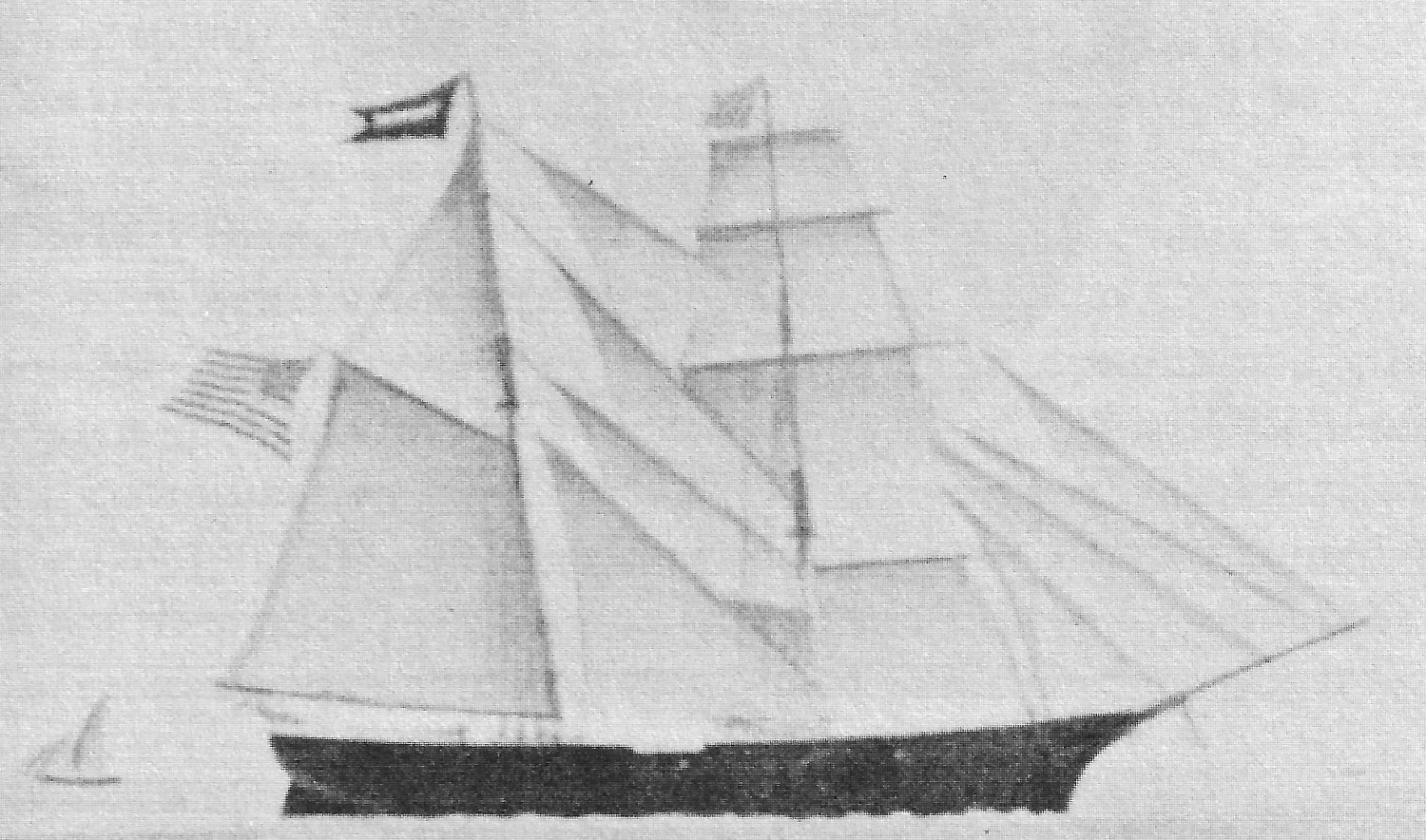
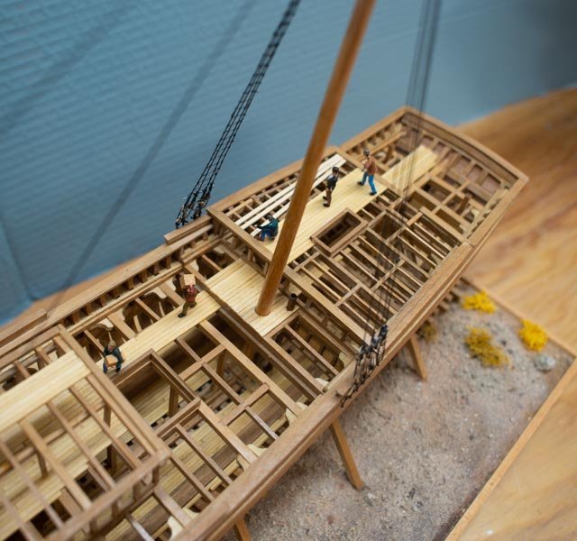
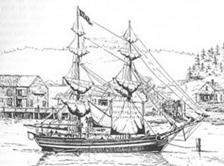
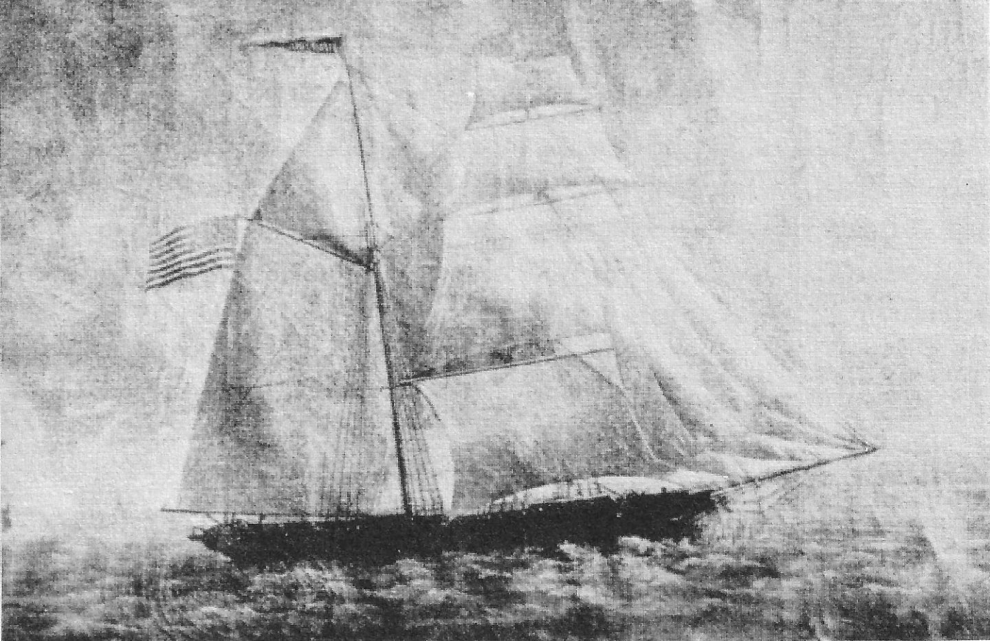
storyboard I just drafted up a storyboard to go with these two models as they are headed to the local Historical society for the summer season. it may be edited a bit before show time. As to the two models, I still need to complete repainting the crew and placing them, set more of the coils and things. set H G Berry on the ways and buy the glass boxes. here is the story that I wanted to include in this file as I keep a work version of these logs for my record. there is a short powerpoint as well as I need to present them at their annual meeting. The Brigs of Boothbay 30 plus Brigs were built between 1823 and 1855. Starting with Caleb Hodgdon in 1823, continuing with William and Andrew Adams in East Boothbay and David and James Adams in North Boothbay, roughly ten smaller 75+/- foot brigs with 120-160 tons displacement were built. Some, like Veto shown here, started out as full brigs with square sails on both masts. They were often converted, as most in the Maine industry found the half brig rig [the aft mast rigged like a schooner] as depicted in the smaller sailing model, to be most efficient. The sailing model represents these smaller brigs. In the middle years the average size of new Boothbay brigs increased to between 180-220 tons. The mid-sized Brig Havana shown here was built on the east side of Boothbay Harbor by Charles Sargent in 1853. His brother Steven and John Weymouth built at least 5 brigs across the harbor in downtown Boothbay Harbor between 1847 and 1855. Also starting in 1849 barks were built starting in North Boothbay and in 1853 ships were built starting in Boothbay Harbor. In the latter years, John McDougall, and the Seavey brothers in Hodgdons Mills, named East Boothbay since 1876, and Steven Sargent and John Weymouth in Boothbay Harbor continued to build larger 100–112-foot half brigs until just before the financial crash of 1857. The model shown under construction represents the H G Berry. She was very similar to the Brig Torrent shown in the picture, and built by Charles Murray and the Seavey brothers in East Boothbay in 1855. She was also the last Boothbay half brig to be launched. Our local builders had moved on to build barks and ships in those final years leading up to the crash of 1857. After the crash amongst sailing vessels, only schooners were built here in the Boothbay Region, before the influx of sailing yachts in the 1890's. During the final boom years of 1853 to 1855, ten brigs, two barks and six ships were launched in either Boothbay Harbor or East Boothbay. When that financial crash came there were two unfinished barks tied up in the financial distress and yard closures. A Bath, Maine owner, the Patten family came and paid John McDougall to complete the bark Ivanhoe in East Boothbay and two local owners paid Charles Murray, our lead builder of the half brig HG Berry, to complete the bark Glen Eden after taking the lumber over to Boothbay Harbor in 1857.

-
Rob I am honored with your visit. I have spent many hours of the past few years running through your incredible builds. I have taking liberty to use several of your techniques...or at least try. Thank you for your kind words. I am all about learning both the history and sharing through talks and exhibits in the local area to celebrate our local maritime heritage. best regards jon
-
Wefalck I welcomed you comments and feel that following them and adding the lower masts was an improvement. My previous build of Ernestina Morrissey, I just put in short dowels where the masts would have gone and was never satisfied with that approach. we learn more every time, so thanks As I. suggested in an earlier post , after analyzing weights and logistics. I believe the lower masts were best installed early. Adding your common sense comment about masts going through cabins, it even makes more sense to set them and then build around them. the weight of the vessel is key. with the 300 plus ton displacement vs the 120 or so of the similar length schooners [ where masts were not installed first], must have been sufficient to take the weight of the mast thanks as always I am wrapping this one up soon and writing the story boards to go with it. thanks to those who joined in
-
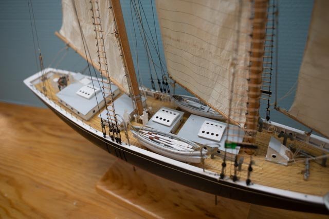
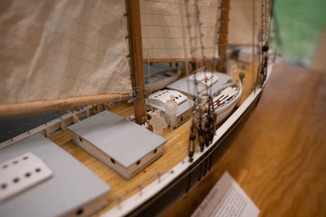
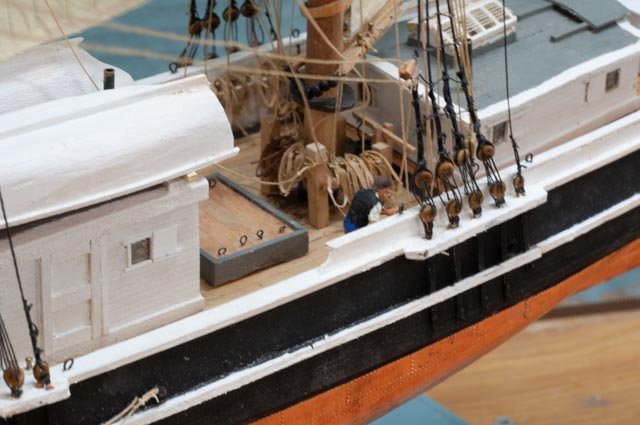
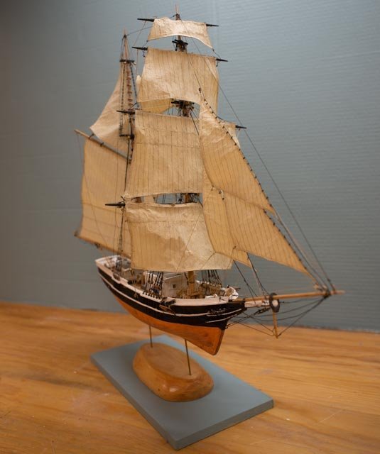
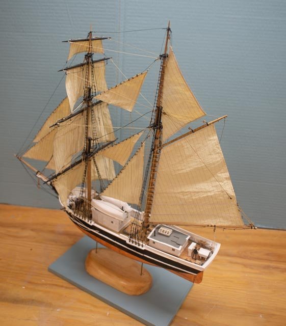
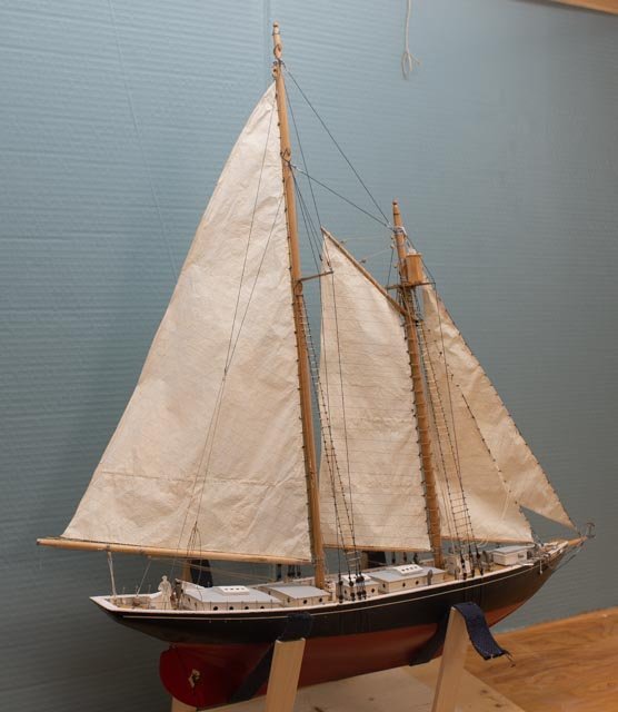
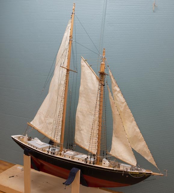
14 sort of done To get …sort of done… I needed to get all the sails on, and basic things on deck, tied off, coiled etc. the set the cabin doghouses. A few oops along the way but as I enter April…one month to show time… I think I am OK. After the last posting, I proceeded to get the mainsail ready and set her in place. I was not sure how the attachment to the simulated track would go, so I was anxious to get going. 1 here we see the mainsail in place. I immediately saw what I had not seen before……eeek. The foresail is just wrong. The yoke is too low, and the angle is just too steep. I was aware there was a problem before but had tried to fix it. Somehow my brain did not focus at the right moment, and I completed all connections to what has turned out to be the wrong sail. This episode is an interesting lesson. Back in an early posting I showed the broadside photo of Blue Dolphin sailing, from which I took most of my measurements. The gaff of the fore sail is angled back away from me into the photo. The opposite of foreshortening, [for lengthening I guess] and it baffles many amateur painters. It got me too. As I had family help last Christmas, we made the sails before setting the masts and other spars…….beware of the risk!!!! 2 here we see a new paper pattern behind the errant sail. There is not a lot of room to play with as the blocks for the throat halyard take up some of the available room. 3 here from the back side we see we can just get that flapper up onto the bronze mast sheathing. 4 and here we are today as I celebrate the stage as a new foresail has been bent. 5 here we have another tada view. What remains now is a punch list. Many of those things that we try to get done but seem to take a bit long to do. 6 This overhead shot shows the basic work of the deck is complete. 7 this view show shows a similar stage in the stern. What remains for my final month: • Get the crew selected and placed. • Complete details like binnacle, third small anchor to secure, boom crutches stored on doghouse roofs, water barrels, some odd boxes, more life lines and things as suggested in the photos. • The small boats. This item is big for me, as I struggle as things get smaller. I would more easily build a 40-inch hull than a 4-inch hull. I need three dories and one whale boat. Fortunately photos show they were covered with canvas while under sail……that is an option anyway. • Storyboards to go over the display. • Glass box…. easy…. I only have to buy it. It is the support of the hull to solve. Do I use brass rods into block of wood? Some type of pedestal? That is for next week. All for now
-
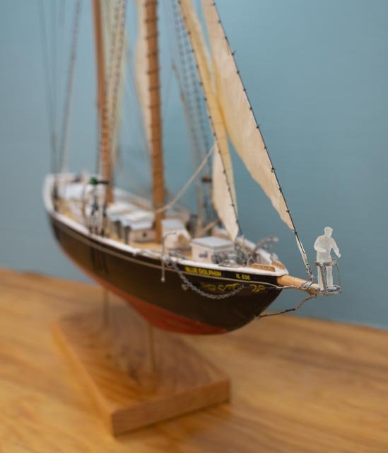
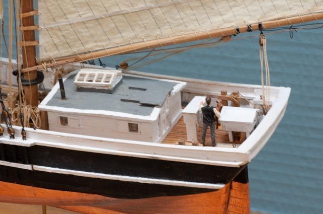
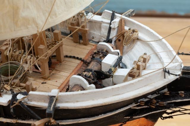
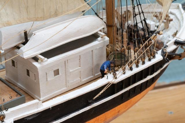
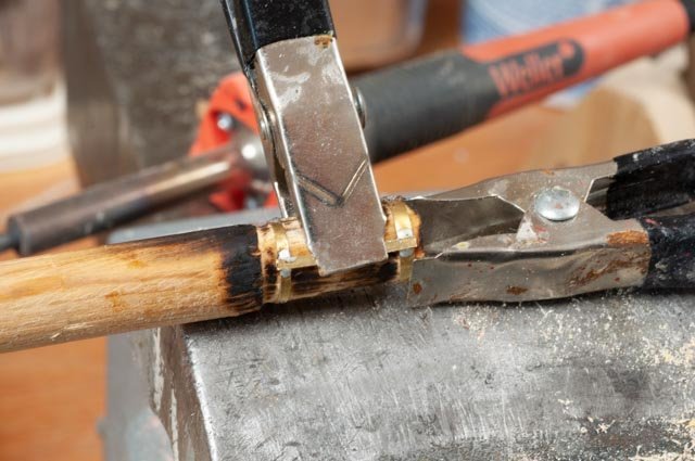
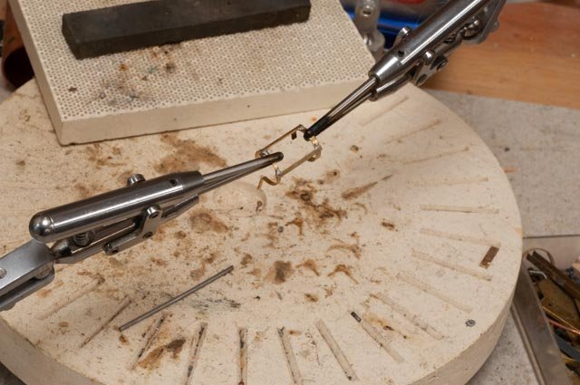
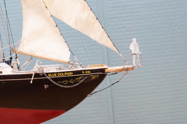
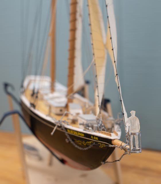
13 Getting sails on the foremast and the pulpit built. This stage is always fun. We finally get to see what we are building come to life. 1 Here we see the first sail final on, lines connected, reefing lines done etc. we are almost sailing. 2 In this view we see the smaller dog house/ cabins, reduced in width, now giving room for the boats on deck. They have be reclad and are ready to set. 3. the forward jumbo and Jibs are on and mostly rigged. I see no down hauls in the photos and am hesitating to add them. Maybe later. The pulpit. I believe that is what it is called????. Arg! soldering loose pieces….. 4 here I clamped the top and bottom rings to a sized dowel and then clamped a brass strip on top of them. It sort of worked. 5 here I am fixing a broken joint. 6 finally we are in place. 7 The ice barrel is now more apparent amongst the rigging. 8 in this view we see the limits of view from the sails. I would call it tough duty to be up there. 9 here is a future, when the model is done, money shot. 10 I think it will be fun to display the model with a crew member ridding the pulpit….why not? should I rig a life line? Happy St Patty’s Day
-
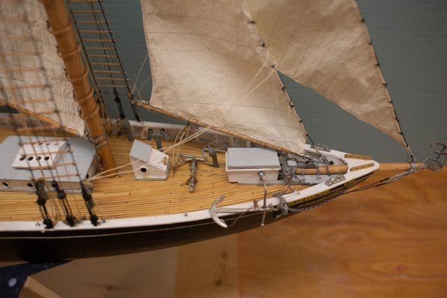
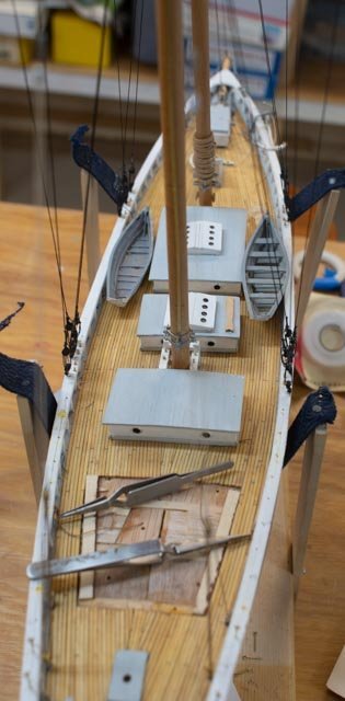
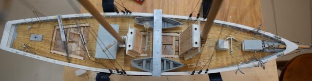
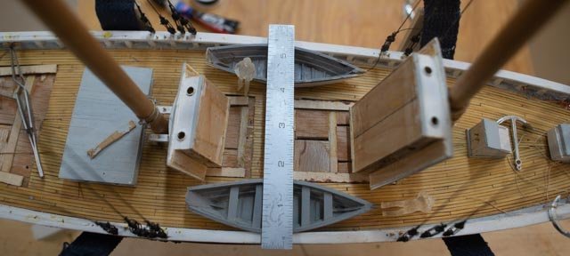
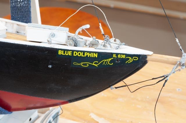
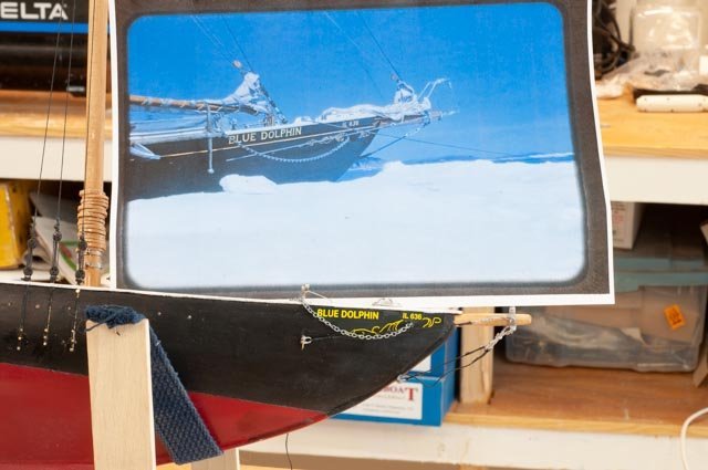
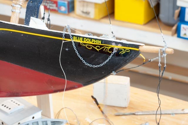
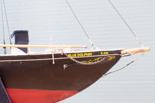
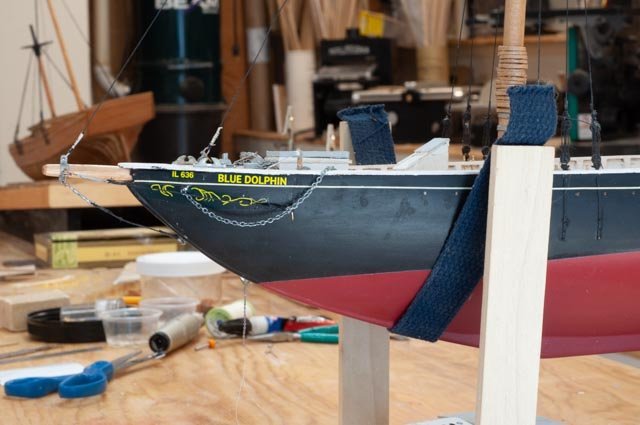
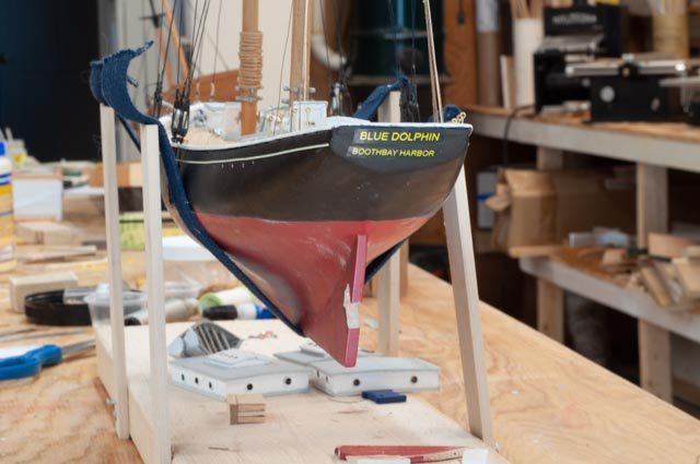
12 time to get the deck work done...but A few fixes need to be done first: When David Nutt visited a while ago, he thought I have made the center cabins too wide. He remembered a lot of room on the deck beside the cabins and the ability to walk inside the dory. He also thought the raised impact on the size of the cabin dog houses below was minimal as the whole lower deck was quite deep . and had full dead room everywhere. Now the masts are in and the bow work coming to an end, I need to sort this issue out. 1 here is an overhead shot of what has been done. The mockup dories come from another 10 year ago build. They represent 5.5-foot-wide fishing dories from a sardine schooner of 1903. In the current build with 10 foot wide cabin and 5.5 foot dories there is clearly no passage…..something is wrong 2 In this photo, from David Nutt collection of a 1952 cruise, we can see a few things to help. • Using the people one can tell the dory are clearly closer to 4 feet wide than 5.5. • Using the dory one can tell the edge of the cabin from center is roughly the same width ……ta da….. the cabins [ dog houses] really do need to be cut. • The passageway is less than 2 feet but still enough to get by So off we go and after removing our portlights, and with a little work with some saws we now have 8-foot cabins. 3 here in an overview we can see the better relationship of cabin dory etc. after I cut the blocks down to support 8 foot in scale. 4. in this view better to see the work to get this fix done. • Decking has to be revised and filled in some more…..not too bad • The house cleaned up, roof decks cut back, cladding added, port lights drilled out and set and then trim added. The Second fix is the lettering etc. at the bow area. 5 look more at this phot I knew something was wrong …but what 6 putting this 1952 photo over it I see my goof. The anchor hawse pipe came almost straight out and not down enough. There is no room for the cove line to pass foreword. So, I dowel led up the hole and redrilled very carefully with a slope. Thank goodness the wood is maple so no issues. I did cheat however and only drilled the hole full size. I did not dill it bigger and insert and brass hawse pipe…..sorry 7 here I took some 1/16 tape I had to be sure there was decent clearance. I also confirmed that this size is not good. I need to use smaller tape. It does not come in as many colors. Oh my. 8 the color is not perfect but close. Here we are back together. 9 the other side finally 10 and yes, the stern is all redone too. All for now... I has started the sails and running rigging as I complete the bow deck work

-
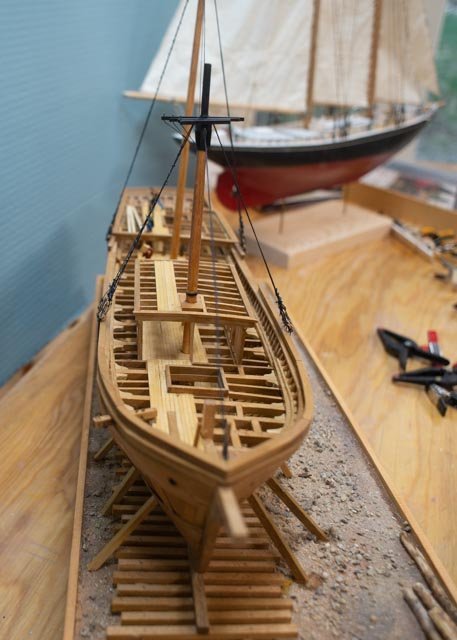
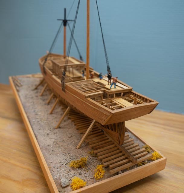
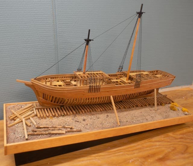
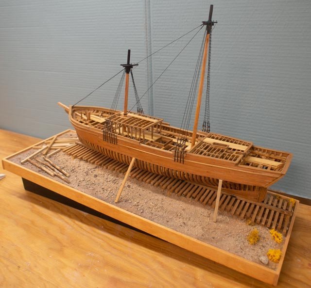
76 almost done. My time is stretched between completing this build, which goes on display in mid-May, and the Blue Dolphin Schooner with a similar deadline. The only work I plan to do between now and display I share below. Small Brig. I can no longer refer to this brig….half Brig that is.... as Albert. Doing more research, I find it's clear enough that Albert was built by Hodgdon, but in 1823, two years before they were clearly land owners and building in what was called Hodgdon Mill and now East Boothbay. Our friendly author and expert says it is possible that they came here and built the vessel before buying the land. Regardless as I have moved into writing the story boards and PowerPoint for the display and introduction talk, that the small Brig model will be just …representative of the small size of roughtly10 brigs built here. I will list their names, builders etc. Views 1-4 …Here are views walking around the model. Remaining work includes about half of the little coils and placement of the crew. We have decided that the tight space where the two models will fit this summer there will be no glass box at this stage. She will only be on display until October. Larger brig…yes Half Brig 5. First an oops. I was moving ahead adding the masts and lower shrouds. I found making the little annealed steel loops to tie dead eye to brass chain plates, I broke three dead eyes. Here the good one to the left and the broken one. Then two that I cheated and used black thread. Time is king and with a small supply of dead eyes on hand I went ahead and used the thread…sorry View 6-9. Here is a walk around of the larger Brig. The lower shrouds are on and like other items, the futtocks shrouds, and rattling’s are only done to starboard. I really like the affect and appreciate that Wefalck challenged that Masts ought be on before launch. He enticed me and it was a great suggestion and yes I too believe on these bigger hulls the mast would have been stepped on land. Views 10-13 Here we see the bow, the stern, the length of the deck and down through the structure. I hope it gives a sense of what one of these vessels was like. next up i will share the display and any new oinfo that comes out of the research. I will also have the crews aboard Cheers
-
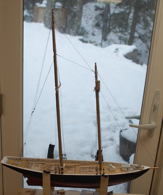
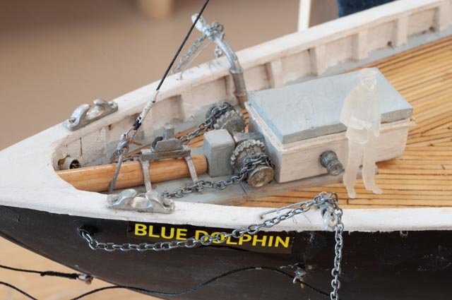
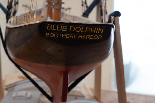
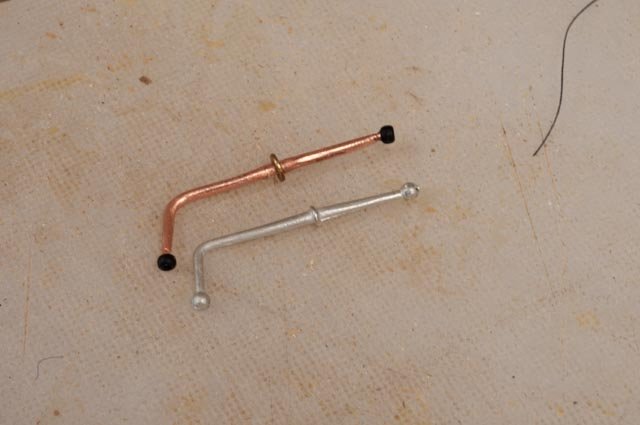
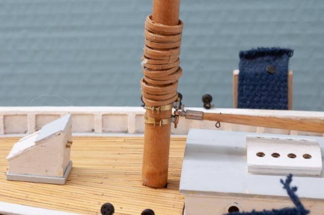
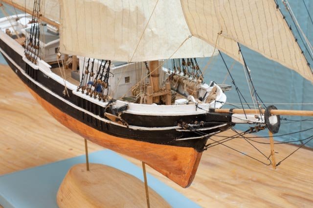
11 standing rigging is sort of done In this update we see a few normal progressions and a few amusing spirts of trial and error. 1 Here against the snowy window we can see the standing rigging is in place. There are few details to work out and the bowsprit to finish yet. Now a series of spirts...some almost ok and some that need more help. 2 Here we see our unfinished gooseneck. A little aluminum paint and instant galvanized 3. Here when I went to my supply of Bluejacket anchors, I found some missing parts…the stock for the one I plan to use. The copper wire brass washer and glass beads make up my attempt to replace it 4. here a few things. I cut down a Bluejacket winch to almost fit the one on Blue Dolphin. I am no machinist who can make his own. I also fudged the bracket for the jumbo boom and the cat heads. Note the lettering easy to read but a bit big. 5 the letting and scroll would pass if the idea is be sure folks can read it. I have looked, relooked and it is just too big….. 6. this stern lettering again is too big. It is more obvious too, so I have gone ahead and re scaled and reprinted all of it on vinyl sheet and will replace. 7. here the crew has arrived and give us a better look at how things measure up. 8. it was fun that one of the figures is perfect to ride in the crow’s nest…”ice barrel” I need to get the lettering right and continue trimming out the deck ,so I can start the running rigging and sails. More important is the writing and preparations for the talks that start in May and go through June.