Jond
-
Posts
874 -
Joined
-
Last visited
Content Type
Profiles
Forums
Gallery
Events
Everything posted by Jond
-
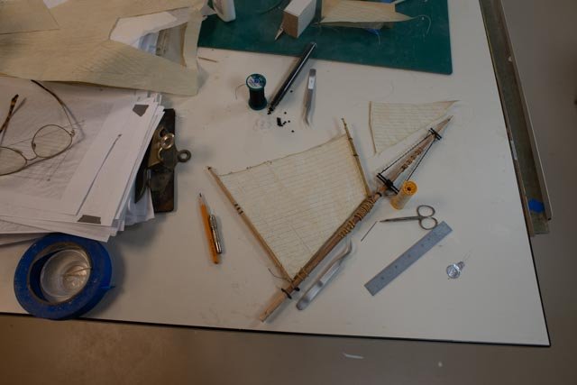
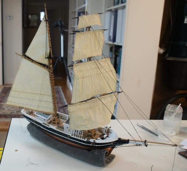
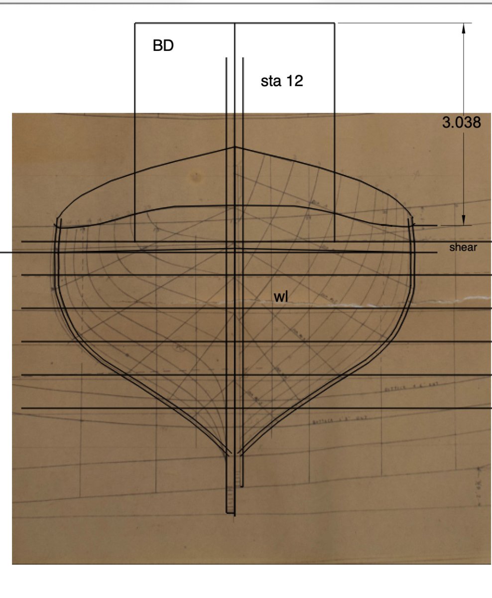
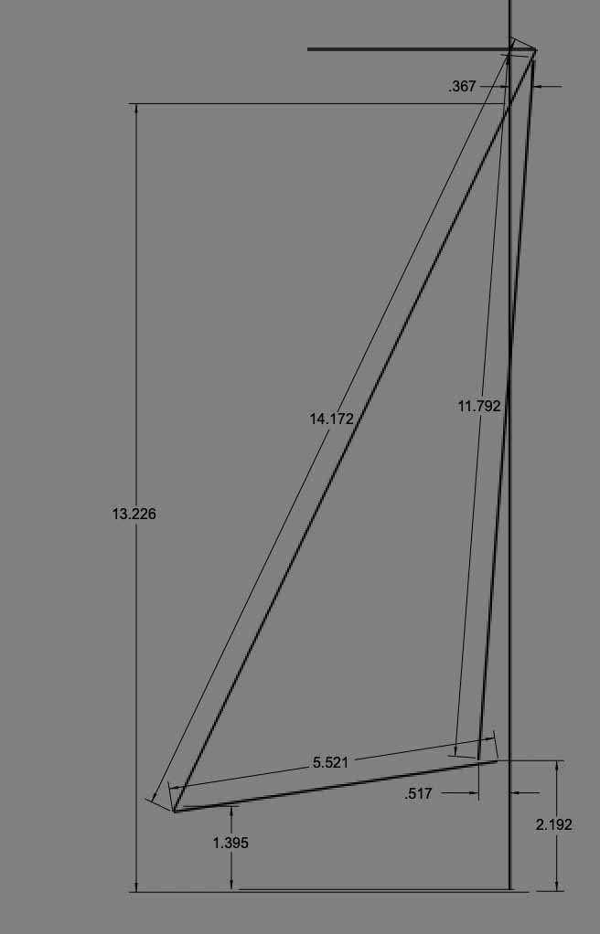
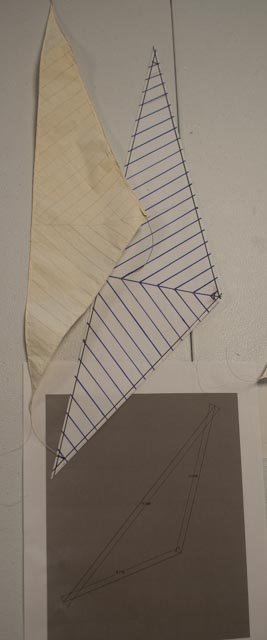
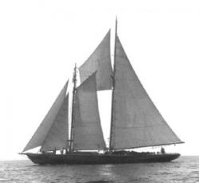
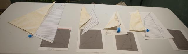
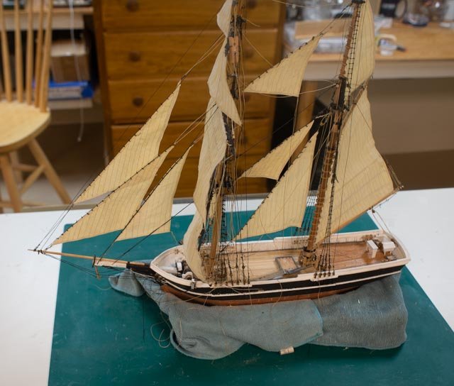
 8 Let’s start with roughing out the sails. To make sails in silk span I am using the same method I leaned with my Ada Cliff build last year. My daughter and I experimented with paining and hanging. I later cut out the sails. This year she wanted details, both to prepare, then also to cut out and prep the sails. So, first I went to the drawing board. 1. here is the cad overlay of the sails 2. here is one version of the detail for a sail that she used. I stated before that we have several photos showing us the direction of the seams. 3. Here we have the marked-up template and resultant cut out and edged sail. Two sides, the luff and foot, got string for the interior bolt rope and the leech got fine wire with end loops. The loops are for rigging and the wire shall hopefully hold some shape when rigged 4. In this photo we confirmed the reefing lines. We also see the only image to include a fisherman staysail. I think I will include this image in the story board but not make this extra sail. I would doubt its use in the arctic.
-
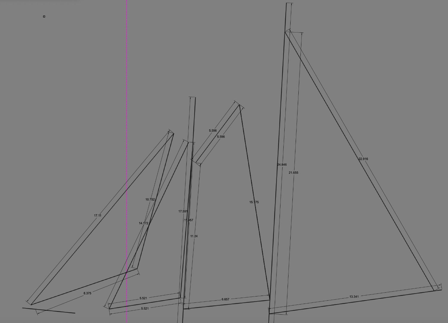
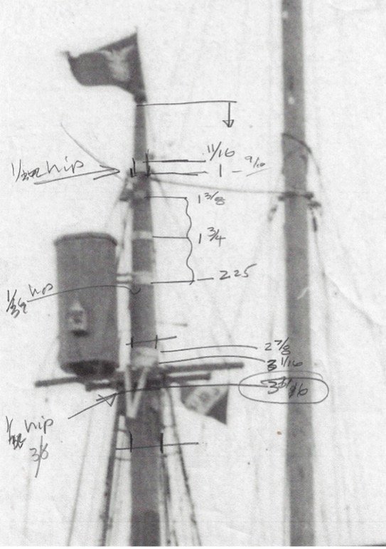
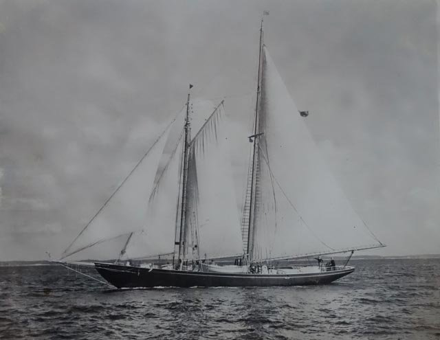
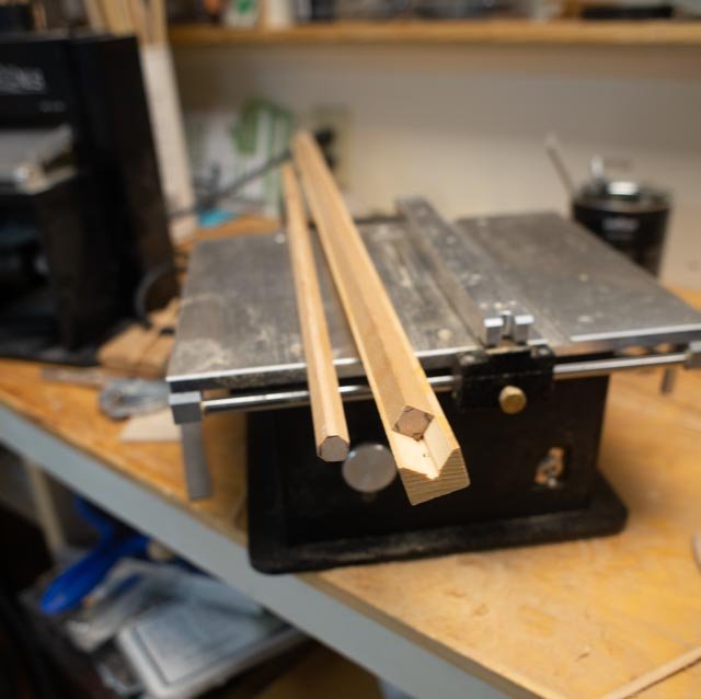
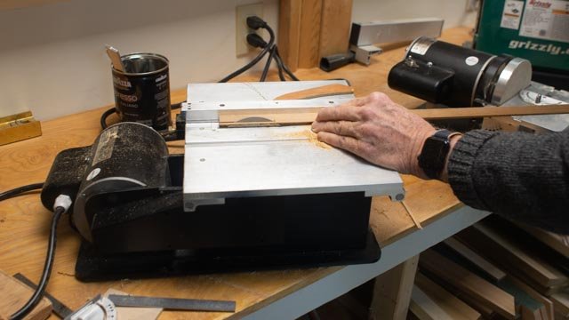
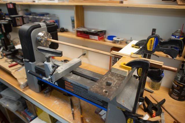
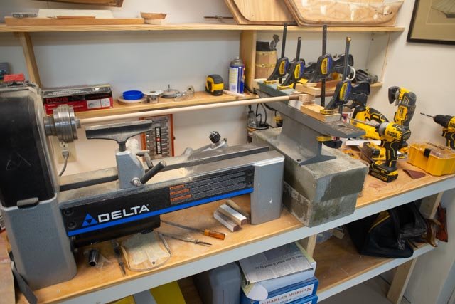
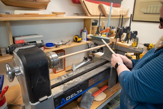
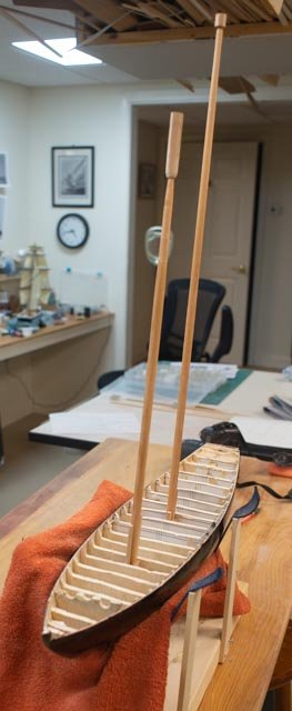
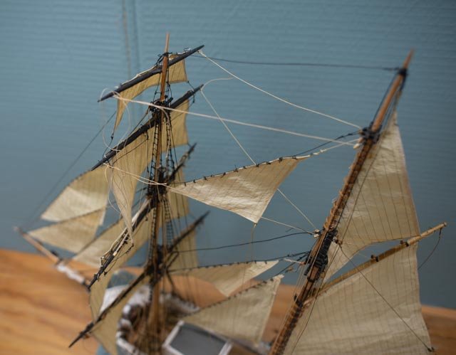
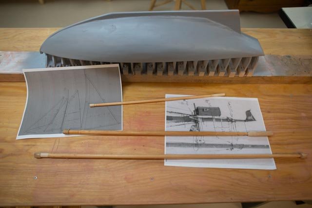
7. research and making masts Combining photos that I have been able to collect, I was able to embed a broadside view of Blue Dolphin under sail for scaling, blow ups to get the seams and reefs figured out, and another one to see the mast top connections for standing rigging. I learned from David that the mainsail was on a track. He remembered it was bronze and ‘big’ and the light-colored hoops on the foresail were ash. He had to varnish them he said. Here are three views I used for the review. 1 gave me a good blow up of the mast head details 2 here it is annotated and scaled 3 This image was embedded for scaling then layout of spars and sails To make up the masts I used a familiar process from earlier builds 4 here in a jig with which I cut off the first corner of a Sitka spruce blank 5 Here I keep rotating and cutting the other three corners to end with an octangle. 6 Here we go to the lathe. I have a mini lathe. This feature means I can only make things up to about 15 inches without some effort. Each time I come up with a different solution. For the short foremast we took my favorite anvil and set is across the bed. A single copper pipe made a sleave to house the lower end of the mast that does not get much treatment. 7 to make the taller main mast we added to concrete blocks and shims to extend the bed and asset the anvil and copper pipe 8 my daughter was visiting over the holidays and wanted to try something on the lathe, so why not. She roughed out the masts as well as the sails 9 here we are with two rough masts
-
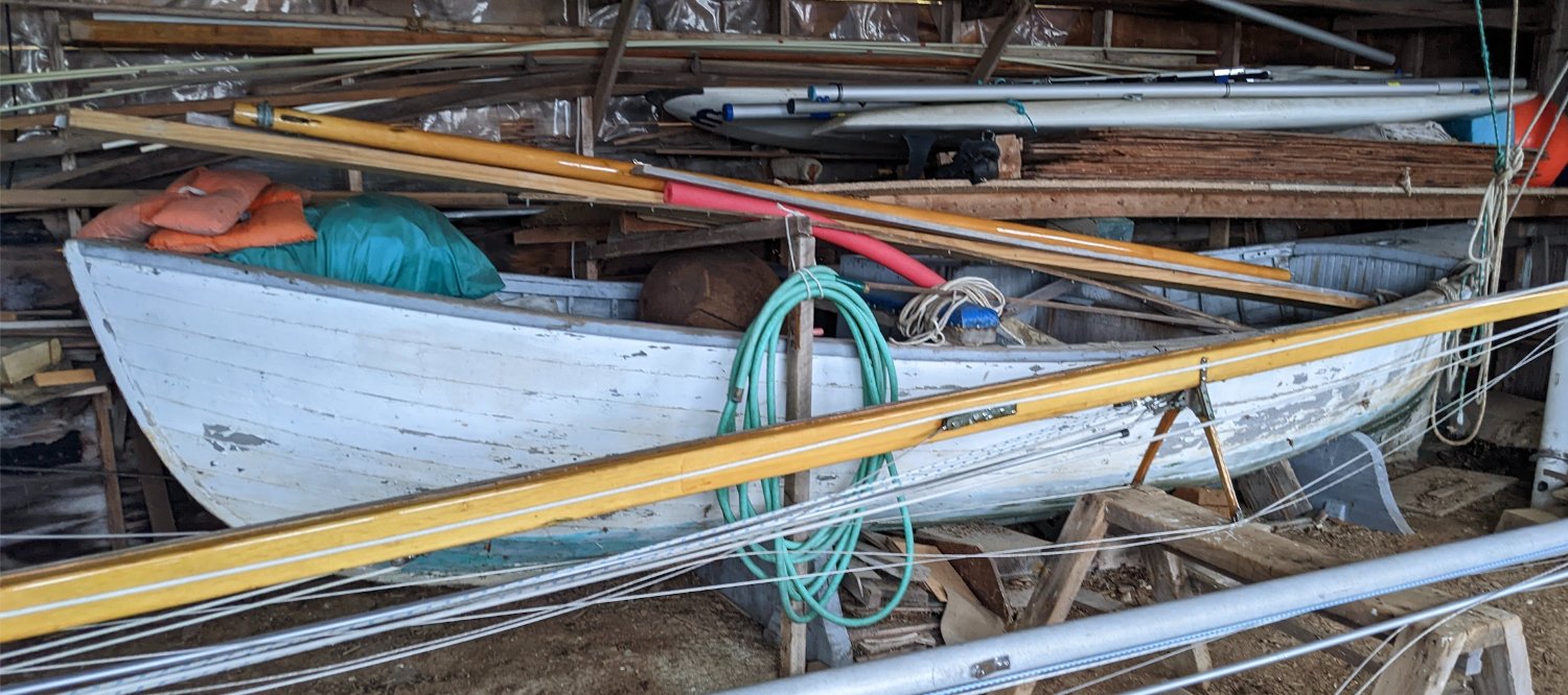
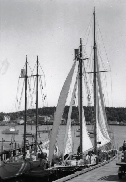
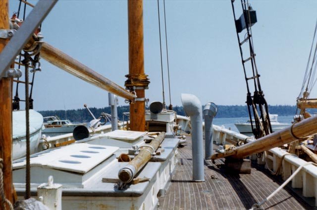
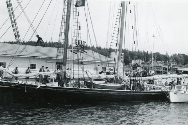
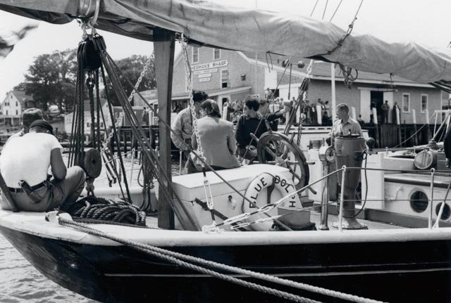
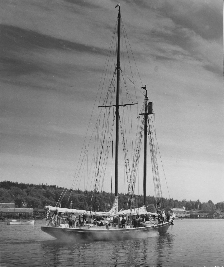
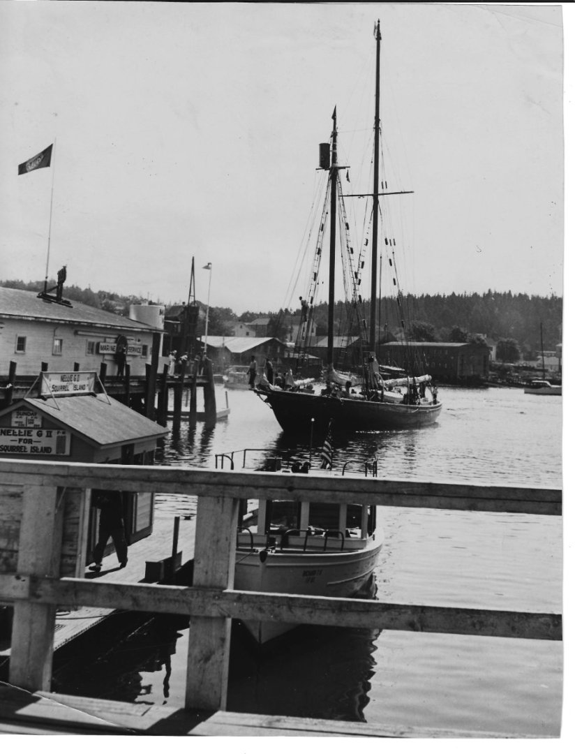
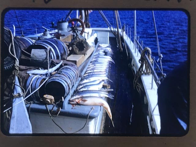
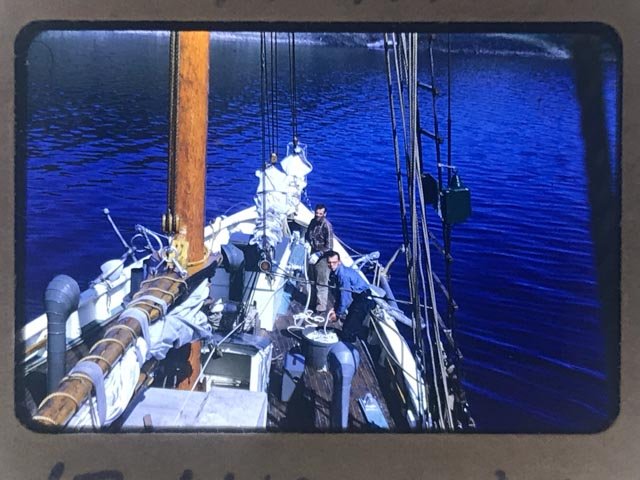
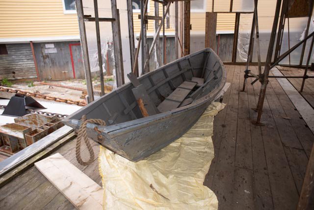
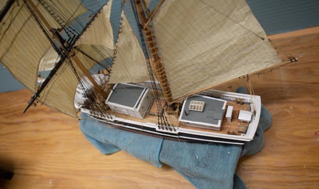
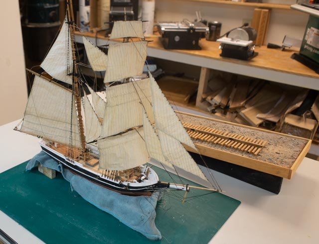
06. researching deck and small boats On a separate project, a group of us are digitizing the collection at the local historical society. My job is to oversee the photos. Through this effort I was able to gather the Blue Dolphin collection. There are 19 photos in the general group and a separate collection by a local student who traveled on the 1950 cruise to Labrador. That student is still in town. Here are three of the general views courtesy of the Boothbay Region Historical Society. 1 this view is one of the few color images. In noting colors and having spoken with David, when in doubt, his dad varnished everything. The deck was fur and oiled, all the spars were. Douglas fir or spruce. Even the ratline slats were varnished ash. Hoops were ash 2 here is one of many I will use to figure out the deck layout 3. In this close we understand the relationship of the rail, bulwarks, gold leaf cove etc. Here are three views from the 1950 cruise 4. sailing to the dock….in a one-hundred-foot schooner. Not bad 5 leaving town for Labrador 6 back home from Labrador Then, David Nutt Jr has kindly lent me the first batch of photos from his father’s cruises in 1952 and 1954. He says he has so many more, and this prospect is great. These, as asked, where to show things on deck, so I could size things and understand what they looked like in that period. I asked for a focus on the deck. Many of them show activity that will go toward trying to retell a story. For the model they will give me a way to dimension cabins and other deck items to try to replicate that era. 7 here looking aft we can scale the width of the deck at the main cabin, see the water barrels etc. 8 here turned around we not the darkness of the deck when wet. Also, I need help sizing the middle cabins 9 in this view, we see the fore sail gaff, several ventilators and again sizing for the companionway I have been using these photos to draw up a deck plan that will let me get close to the original. A second part of the deck is the search for the two types of small boats. The whale boat, as David Nutt calls it, is sitting in his barn. Wow!!!! I have the first of what will be sufficient pictures. 10 here is the whale boat still in storage. There were 3 Dories on board during these cruises. The story is not yet fully clear. In different photos I see a different dory profiles, and occasionally only 2 on the starboard side of the deck. It is possible that different dories made different cruises. David remembers the dories that were on the schooner for all its final 20 years in Boothbay and that is good enough for me. He believes two of them went off to Detroit apparently with the schooner in 1972. A third remained with David all these years. Last year he donated it to Ernestina Morrissey in honor of his father…….not bad aye! This is a small world. 11 here is the dory at the shipyard before restoration. In the photo she is sitting under the bow of Ernestina Morrissey. So much more to learn.


-
Brigs of Boothbay Punch list This update is just my thinking through priorities for the upcoming season. We are having a special display and talk on the well-known schooner Bowdoin this summer as she is scheduled to pass through Boothbay Harbor again on her way back to the arctic. Therefore, we plan to do the following: move and expand the current Bowdoin display out of the Vessels and Captains of Boothbay display at the Boothbay Region Historical Society. I will be working on the expanded display that will tell the story of the first 60 +/-years of Bowdoin and Boothbay. The Brigs of Boothbay display will then take the place of the Bowdoin. It will need both models and story boards along with a little talk. To see all these moves, happen, I need to focus on this build, the Blue Dolphin build, the three stories of Bowdoin, Brigs of Boothbay and Blue Dolphin. All need to be ready by May…..oh my!! 1) Half brig Albert a) Complete braces and tie off…one to go b) Add 3 pins and tie off main stay sail line c) Complete jib sheets…two to go d) Make coils and set…30 plus to go e) Set cabins f) Paint and install crew…3 g) Drill holes for brass pins. h) Make stand i) Size and order glass box j) Optional small boats. To be added later after small boat effort for several models together. Likely to be next winter 2) Half brig H G Berry a) Complete cabin wall frames b) Complete bitts and things c) Add chain plates d) Set lower shrouds…set two and see. Perhaps set four and set a few ratlines? e) Set lower stays. f) Size and order glass box g) Drill small holes for small pins for keel to sit firmly on the ways center rail h) Set supports posts… decide if milled posts or raw posts i) Paint and set up crew….5 j) Optional hoisting activity. Build a gin pole and rig something being lifted to deck. Then consider having it be rigged to traveler shackle, like whaling tackle to show construction use of masts. Likely to be next winter build 3) Storyboard and powerpoint talk: I have lots of material. I just need to find the time to focus. I will likely only make a few storyboards to post over the models to explain their intent and the brief saga of our 32 Brigs. The power point will be perhaps 8-10 rotating slides to be added to the current slide show of captains and vessels 4) The Bowdoin story boards will focus on the building of Bowdoin here in 1921, being hauled and maintained many times and then replanking in 2021. The slide show will be available for a talk on the history of Macmillan and the Bowdoin before her sale to Maine Maritime Academy. The intent of that talk eventually will combine it with the Blue Dolphin. Blue Dolphin has its own build. There tomorrow.
-
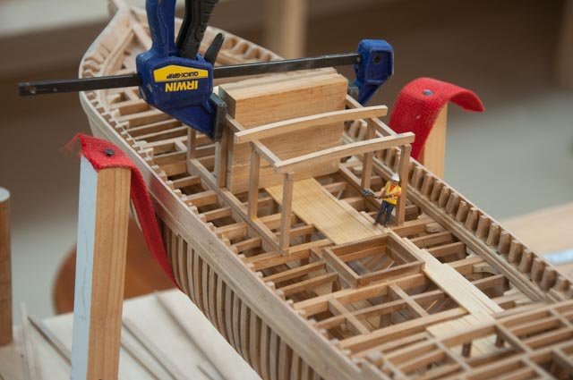
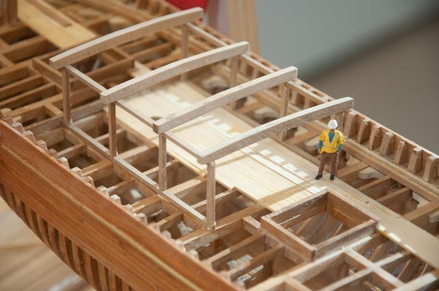
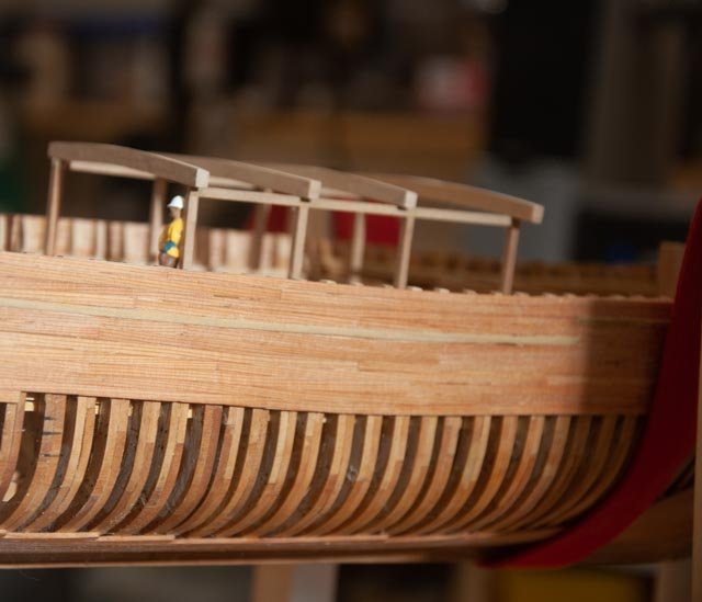
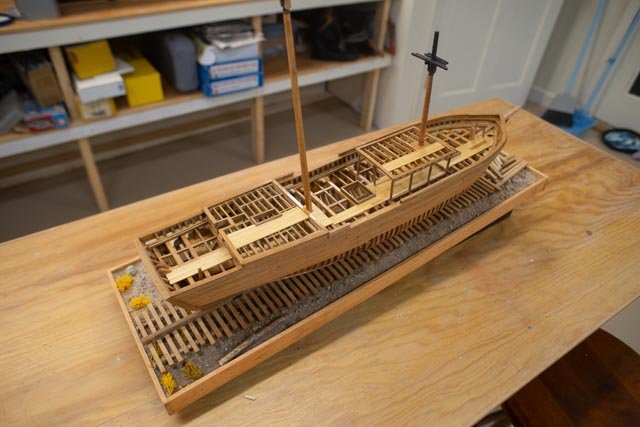
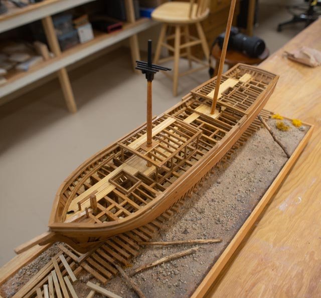
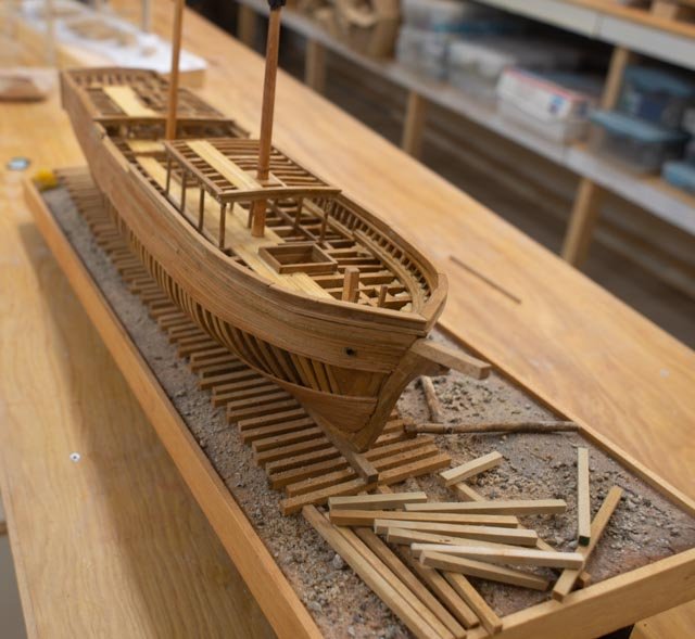
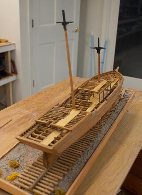
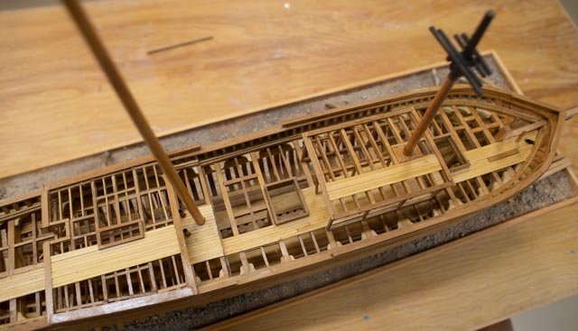
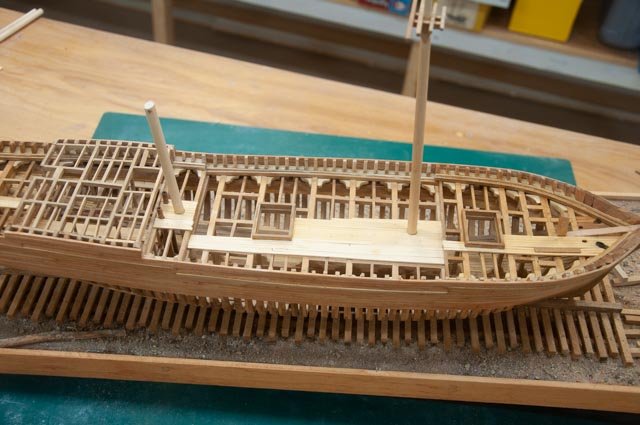
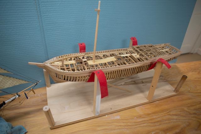
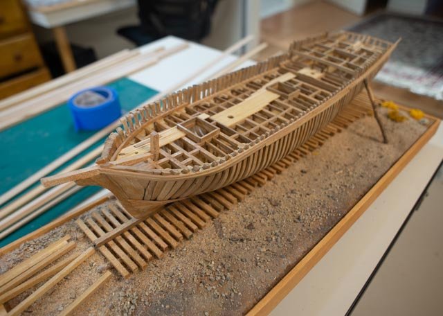
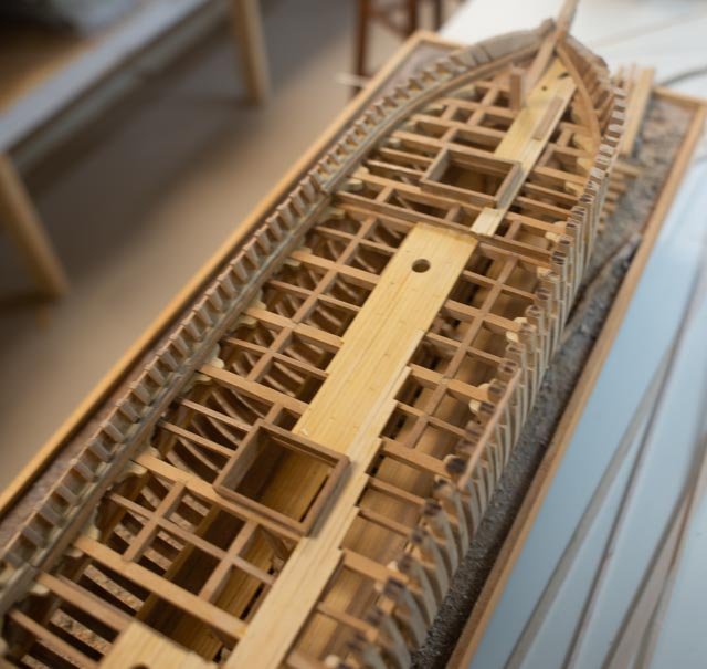
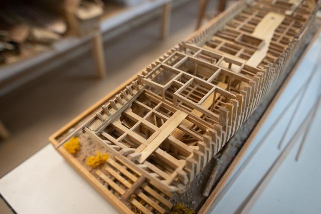
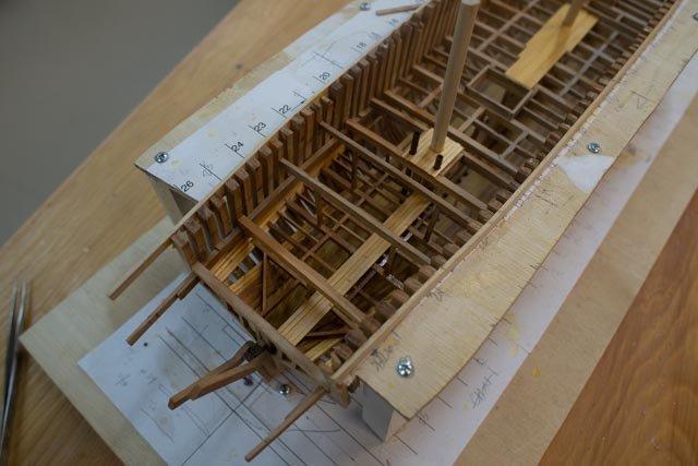
75. H G Berry the rails are on ! An update on the progress of deck work. First up is an oops. I have started a schooner build that I am building at 1:48 scale. This build is at 1:64. I got mixed up and built the rough frame for the deck house way to big.. 1 here we are ..oops a little big 2 and here we are redone at our scale 3 in this view we see the side planking and frame of the fore cabin. The figure seems right compared to the painting so onward we go. Today I am celebrating being sort of done with woodwork. I am now into the punch list phase including perhaps 15 or 20 miscellaneous frame pieces that are missing from the cabin walls. Here are a few views 4 starboard side 5 port side 6 the bow 7 The stern. In this view the masts are most apparent. 8 looking down where we see cabin top, the deck and inside of the hold. This view is to help the viewer to better understand the making of a vessel this size as she'll be sitting next to the smaller version under sail. Looking ahead I will begin some iron work. I will set a few shrouds and stays to support the two masts, tie on the rudder and few more details. I will then figure out what if anything will be added using the figures I have to animate the display. Of course I need to do the same with the other half brig where I am slowly, ever so slowly, completing the rigging. All for now
-
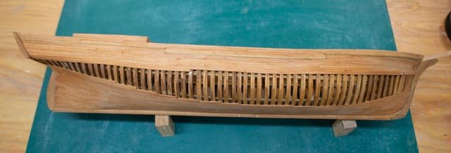
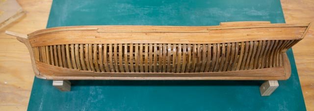
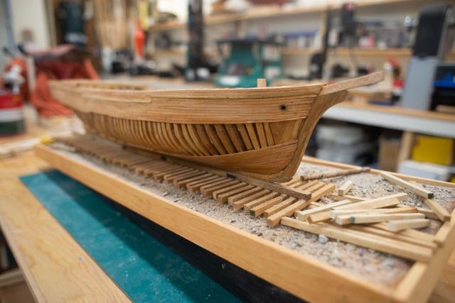
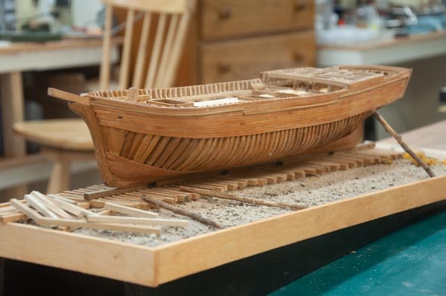
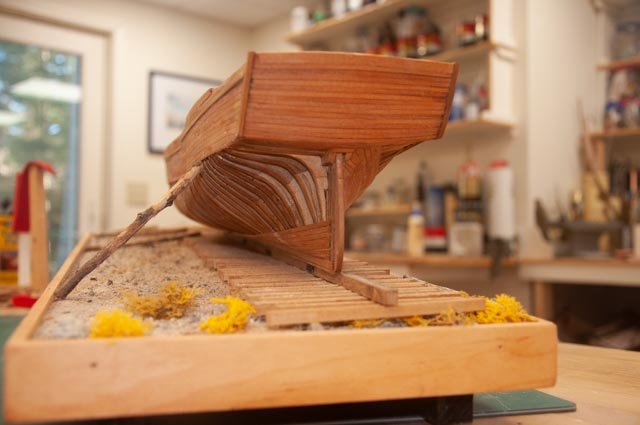
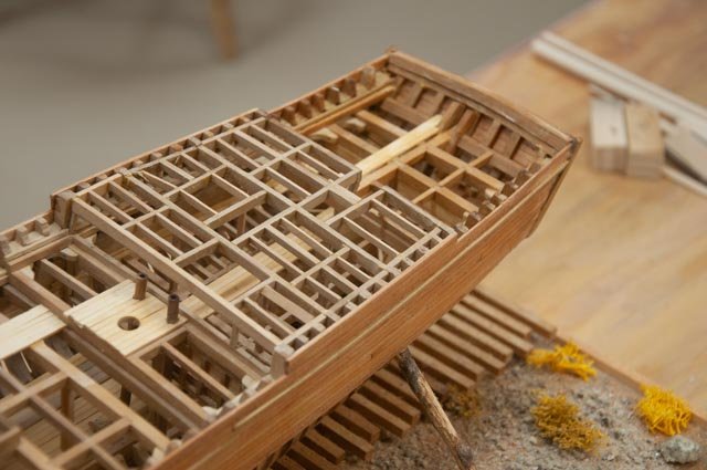
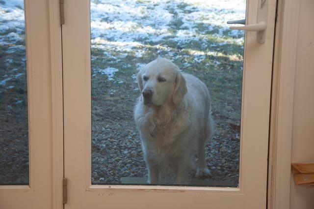
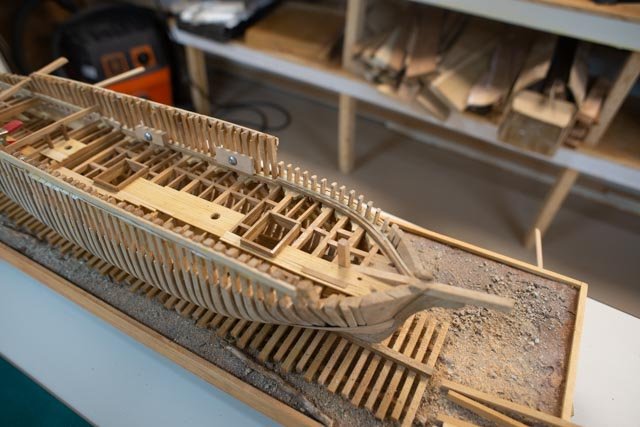
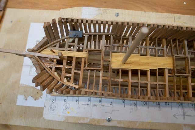
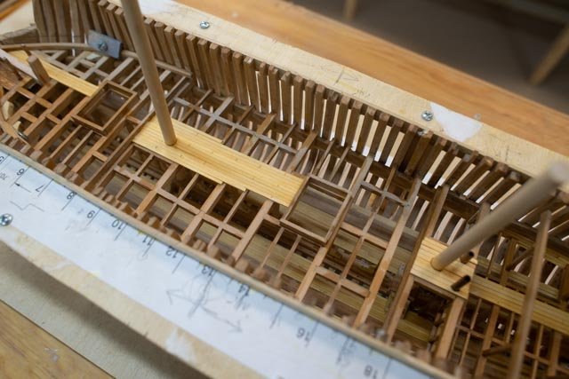
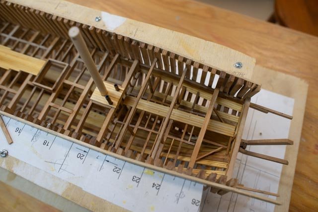
74 completed the hull….sort of This update is to celebrate the end of adding planking to the hull. I have decided to keep the rest open. I cannot call it complete as there are several details to be added and the clean-up [ remove stubborn glue and dust from inside of frames] and oil it all. I use tung oil. 1 here a few days ago I completed the port side. 2 today I completed the starboard side. Too bad this is dry January! 3 here we are sitting on the ways. On this starboard side we have more of the planking completed and we are up against the side. 4 here is the port side with room to show some activity. 5 I had a lot of concern on how the stern would come out. Honestly it is a little bigger than I wanted. To look ok, I needed all the planking so the fashion pieces could go in to make the corners. The soft red cedar is not good for sharp ends. 6. I also added the rudder. I will be adding some iron work later as I trim things out. I also need to figure out how I plan to prop the hull in the display. Let’s look at what remains before we move to punch list and finishing 7 here is the bow section. I have done more on the starboard side. The hawse pipe went in this week. I will add bitts and things after the rails. 8 here in the mid-section we see at the moment the foremast. I am not sure what to do here. I may add the lower main mast but that really opens a rabbit hole. I have the framing for the fore cabin roughed out and want to get it in and then consider if I add any masts. 9 here I have the rough framing almost done for the main cabin. It has more framing as I suspect it had a light roof decking. I will put cabin top decking and then think of if any more like skylight frame. 10 Well my helper keeps me getting up to open or close the door, she only yawned when I explained todays milestone…that is how it goes.

-
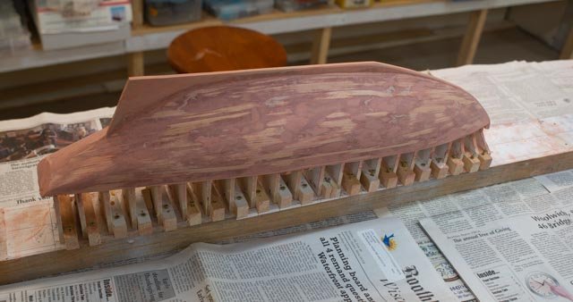
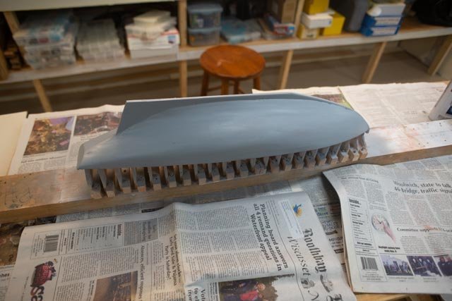
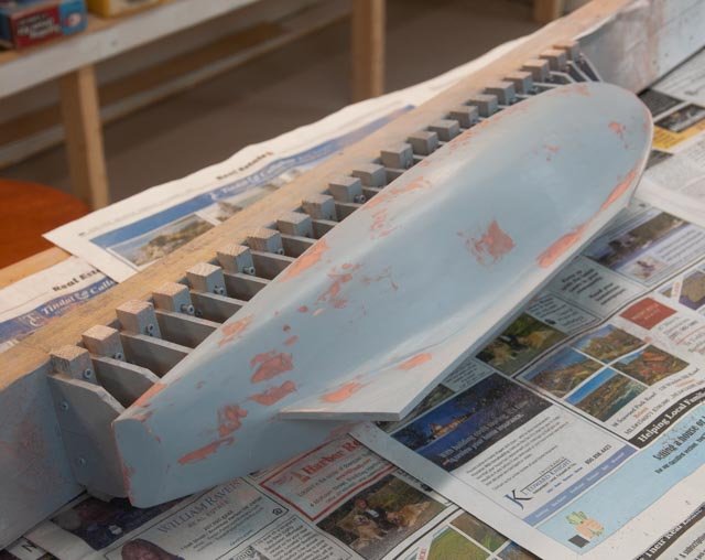
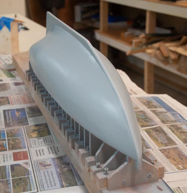
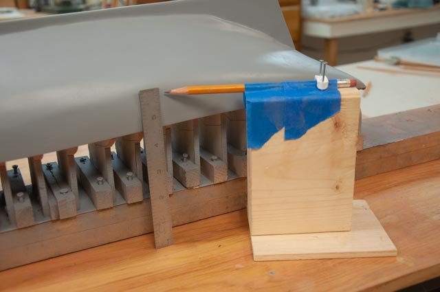
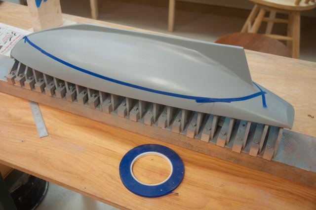
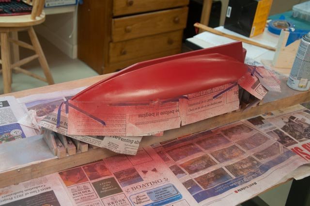
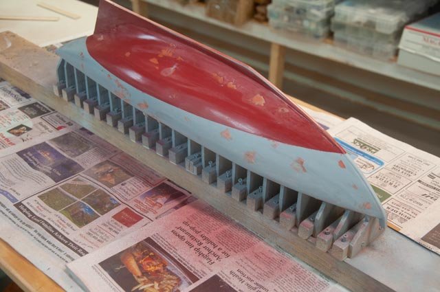
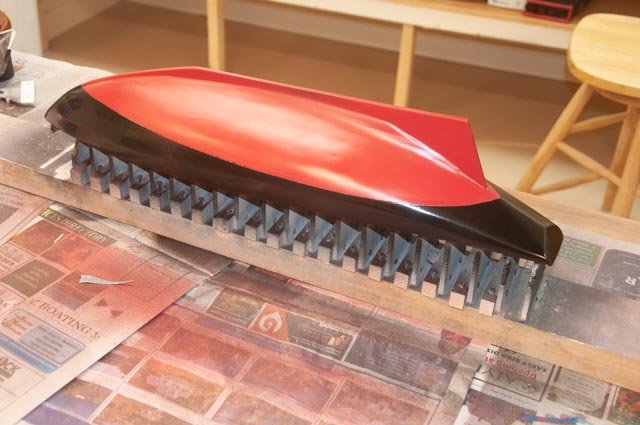
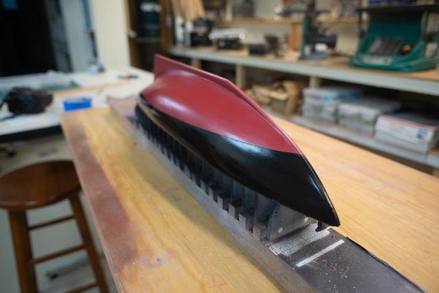
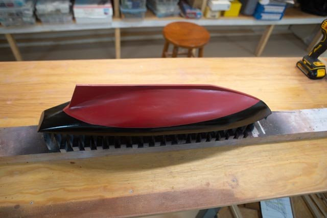
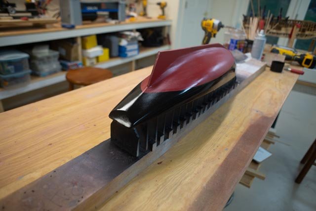
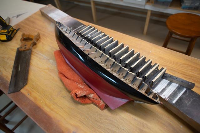
05 we are off the building board !! This update is to cover the completion of the exterior of the hull and getting her off the building board. The focus for me in this build is to get a better finish on my hull than previously achieved. I own, but have yet to try, the spray painting set up that so many true modelers use. I will be using "rattle cans" again. I promise to try the spray gun one of these days. The sequence below takes us through about 7 steps , many just repeated efforts to get the preparation better for the final product. Here we go 1. this is using Bondo glazing putty, used normally for auto body work. It is one part in a tube and dries relatively quickly .That is why I really like it. imagine in this photo that eventually it is hard to see defects. 2 I use the filler primer. It helps a lot for us amateurs 3 I expect to have one more sequence but had three times where I use the putty, sand and repeat. 4 this sequence is repeated about three times 5 here is the fool proof low tech water line marker. The pencil lead is 3/16: less than 6 inches off the table, measured from the station patterns. 6 here is ¼ "painter’s tape. It is not perfect but bends 7 I had to spray twice. the first time I used painter normal tape and it pulled off spots of the primer. This time I used newspaper and the light 1/4" tape. Talking with David Nutt jr. this week he remembers as a kid having to paint the bottom with red lead. He told quite a story. I apologized for selecting satin finish "heritage" red at the local hardware store. Note the lack of ugly orange that was in the real stuff from the era. He laughed. 8 Even after the first coat, we find little defects coming through and need to putty sand and paint again. 9 thru 12 Finally we stop and say enough is enough. The finished job ......also the incredible warm weather had let me open the shop door and paint here and not take everything to the garage. And now..... ta da ....off the board 13 end stage 1 All for now
-
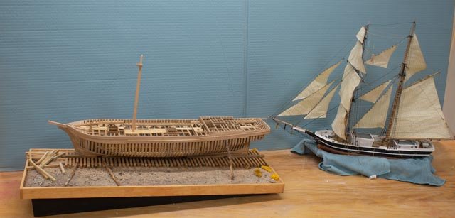
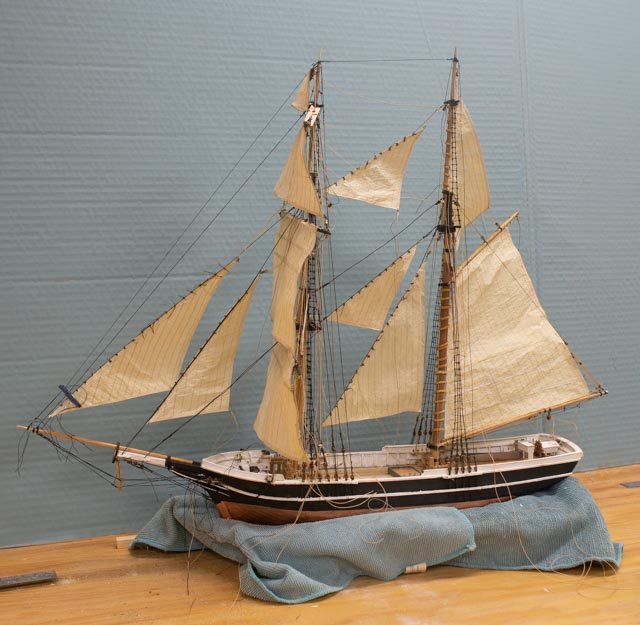
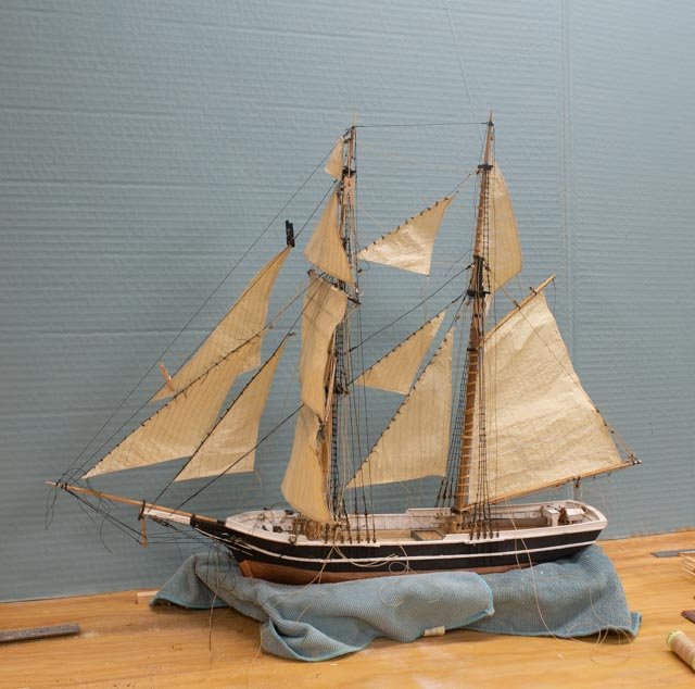
73. today I wanted a New Year’s photo shoot to record where we are as 2022 comes to an end. As time is now divided with the new schooner build, things are going slow. That is not a problem I think, as I don't need to have this build done until May. 1 first up.... what is done since last time. The stanchions are almost ready to receive the main rails. The planking is progressing on both sides, but I will be adding more. Lots of smaller frames and the fore cabin frames to add. In this view we see the new sling support to hold things as work progresses. The display. I must figure out the combined plan. The two half brigs are to be displayed together to tell the intended story of 32 brigs built here between 1829 to 1858. 2 In this view we have two vessels going in the same direction. Perhaps they are better headed toward each other. That solution will come together much later after preparing the story boards to be displayed behind the models. The larger half brig H G Berry 3 the larger half brig is shown to be under construction. The port side has the optional space to show some construction activity …. what to do?? 4 The starboard side will have more planking in place. Also note I have stepped a partial foremast. Should I do this step and then partially support it with some shrouds? What do I do about the much taller main mast? One suggestion is to have it on the side ready to be installed. Once the rails are on, and several other missing frame pieces are installed, I need to clean it all up and get some oil on. The small half brig Albert 5 not much has changed in the last few weeks. I peck away at the rigging 6 here we see a mess of loose lines as I am slowly getting them tied off, and I have started putting on the coils. The cabins are sitting loose for the photo. I cannot install them until all the lines are tied off. 7. here I have started the braces. They are the last running rigging to go in. everything is loose currently. all done for this year.....Happy 2023
-
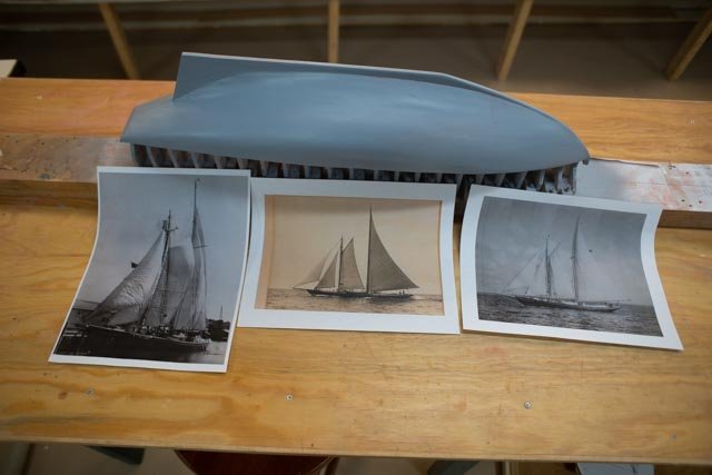
New Year’s Eve photos added to recent post Today I wanted to record what is done as we close the year. I will do an update of the process to get here next week some time. 1 Hull….here is the second prime coat over glazing putty. The blemishes are reduced, so about two more sequences of sand putty sand and prime to get ready to paint. In front we have three photos that I used to design the masts and sails 2 Masts….here we see the other side of the hull and the cad rendition of sail and spar design taken from the embedded and scaled photo. Also, there is a blow up that shows the detail of the mast tops. The two masts are Sitka spruce. 2 Sails. Here the patterns were made using photos for seem direction. More on sails later as all the finish work needs to be done next. Happy New year
-
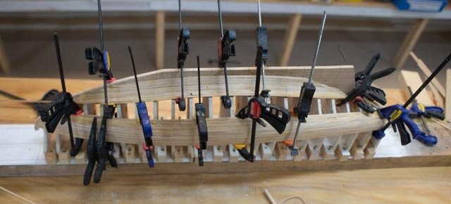
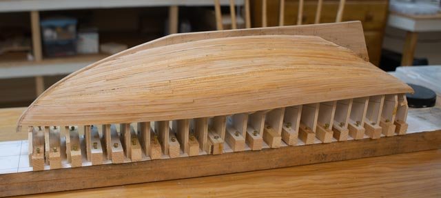
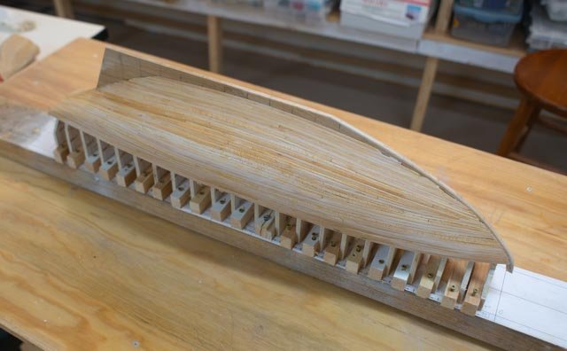
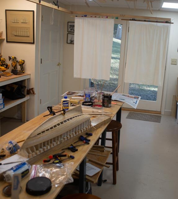
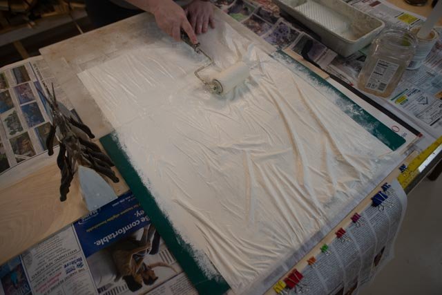
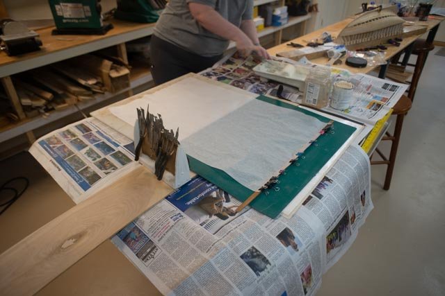
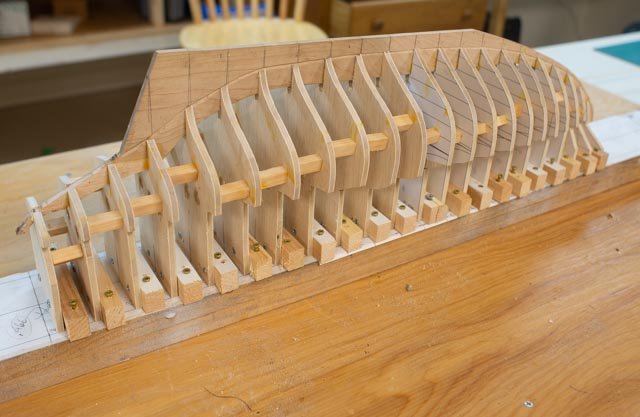
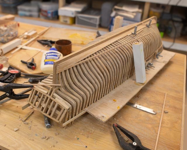
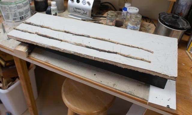
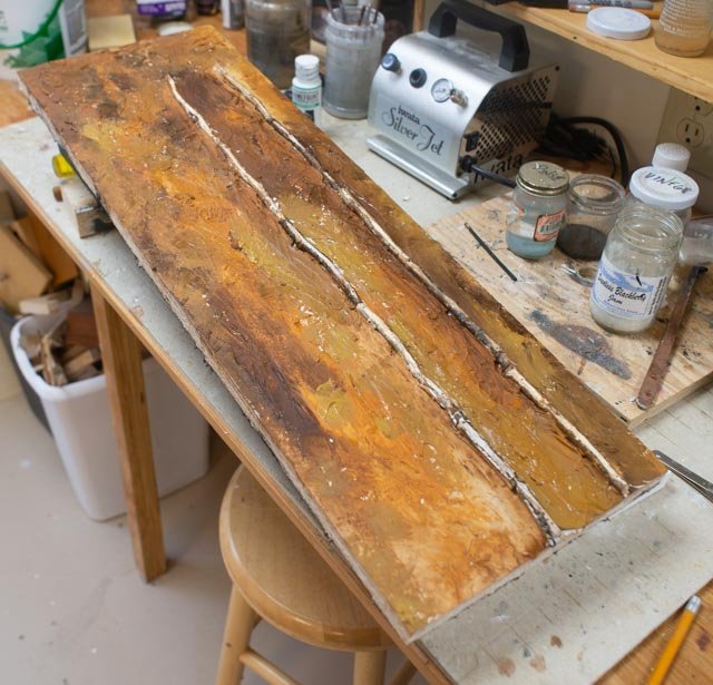
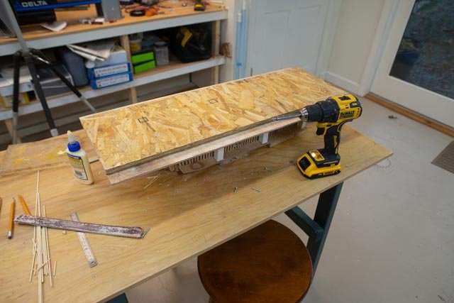
O3 BD 2022 year end update. The hull is planked! My goal was to get the hull roughed out in this first month of the build. I also enjoyed the experiment to try to use maple for planking. I learned how hard it is to work with and perhaps why it does not show up as a choice of materials that I have seen before. Fortunately, this to be Bondo, then putty, then a painted hull. 2 As I began the middle band, I was able to use simple clamps until the last few planks. I then used wedges. It has been great that my daughter visited us again this year for Christmas. Last year she helped me with the first time learning and production of preparing silk span material ready for the sails on the schooner Ida Cliff. This year she again helped. To do big sheets it really is better to have two people. 3. Here is the set up. A lesson learned was to take a thin strip of wood at the top end of the sheet before painting and place at least 6 small clips. This approach would mean that when picking up the wet silk span there are many points of tension, not just two hands. One then adds just two bigger clips to hang the wet sheet to dry. As we found last year latex paint works fine. We used up the can. 4 while rolling on the paint, I continuously sprinkled more water into the paint and roller at the roller pan. I also lifted the wood strip to drag forward the sheet, so the line between the green cutting pad and cement board would not become a defect in the paint. Thank goodness for those strips of wood. 5 here we have hanged the completed sheets at the end of the work bench. These sheets are the full size as they come from Blue Jacket. The hull is a day from completion underneath as the paint dries. And just a day later we celebrated. I have set all the planks and done some rough sanding. 6,8 Here are two views of the hull. Planks are on, and the first rough sanding is done. I need another session of sanding then will fill and make smooth for painting. The maple was too hard for me to twist in all areas, and I have about ten little holes at the transition to the keel. I am not into steaming to make things more pliable. I made all the planks 1/8” wide with a few of the finals a bit less. My spiling was simple sanding since this hull is painted. Happy new year
-
just a quick update as the we head into the holidays. I am experimenting using maple as the planking material. It is definitely hard. It doesn't soak up water and twist . There will be a lot of mending to do. The first two bands are done, now the fun one in the center.
-
Ron Thank you for dropping in. It was good to catch up the other day too. I have enjoyed some of your other anecdotes regarding your personal history with this wonderful schooner. I hope as we get through this build and the fun next summer you think more about building one.....maybe and RC version. cheers jon
-
thank you keith. she really was . I just found another article written in 1995 after she had unfortunately met her demise, sinking in a canal near Detroit. She apparently is still there today. She had left Maine in 1972 after a 24 year career here sailing often to the far North. The owner David Nutt Sr was reminiscing for a local paper in that article . He commented in passing that she often sailed over 12 knots, leaving many in her wake. On one trip she returned from labrador to Boothbay in five days. I am starting to get access to more pictures from the owners son to help me understand the deck design, and look forward to learning more of her story. cheers
-
mast in or out of the H G Berry one the ways I did a little digging into weight, rigging logistics and the like and viewed some more images to see if I can at least rationalize a point of view if a 112-foot 320 ton rated half brig would have been launched in a small Maine yard with or without spars. The recent book I referenced earlier by the recent retired curator of Maine Maritime Museum tells of the 200 years of Maine ship building. It had very few images of early launching. It is clear in that volume that across Maine by the 1860’s, all the big schooners, Downeaster’s etc. had their masts on as they slid down the ways. Here we go for 1857 in our village…Let’s figure out the size of the masts. If I used the Torrent painting embedded in CAD and scaled. The lower fore mast was 45+ feet plus housing and the lower mainmast 65+ feet plus housing. If I use the formula in Crowther’s book of 1 inch diameter to 3-ft of length, we get 18 inches and 24 inches. If we take a mean value of 50 LB per cu ft for average spruce and other mast material, we are almost ready to calculate. Before we do though, I suspect the foremast was fine at 18 inches. The Crothers formula of 1 to 3 is for ships. The schooner rig of the main mast I suggest could be lighter, I am guessing closer to 20 inches [that is the real Ernestina Morrissey [110’ OD] schooner today] than to 24 inches. Considering the taper loss of volume is a bit of a guess. That said, and a little math later, we have the foremast at say 2 plus tons and the mainmast just over 3.5 tons. How does one handle a 75+-foot-long [ including the mast housing below deck] spar that weighs almost tons [ including rigging]. i recommend the lifting point needs to be above center say 40-45 feet above the deck That is 50 +’ feet after launch and perhaps 65-70’ on shore. As late and the 20th century, 100 -150 plus ton schooners were launch bare and masts set on the dock. So truly I am projecting here. Now of course it is possible to lift a pole with lifting points below center, but why would you? It would lake more cables and winches and men and raise the risk. In my opinion the 45 feet long plus foremast would have been easier to set while on the ground. It would then be a part of the rigging of the second mast either on land or in the water. I have no basis to say, but suggest the 77-foot mast would have been easier to handle in the water if there was a common dock with a pole needed to step masts. It makes sense though if a gin pole is set up to set the foremast. Why not use it and the foremast to set the main mast before launch. My current plan is a bit simple. Just like the Ernestina model, I do not plan to complete all the rigging and sails. I am trying to show all the bones and using framing the insides of the vessel. The second vessel Albert within the build has all the spars and sails and lines etc. and is rigged the same way. Together they make a display to be …the brigs of Boothbay. I like to insert stub masts as artistic license and to give a little help to the average non nautical audience. The question Wefalck raised though gives me the idea to consider making up and setting a 9-inch-high lower foremast. I might even hang a few shrouds and forestay. Something to think about ! cheers
-
What a great question. I am going to do a little searching before answering. I'll be back tomorrow. they did both here over time. My gut says that bigger vessels with huge heavy masts were easier to rig on land and the ratio of the mast weight to the hull was less significant. Thus navy yards, clipper ships, the big schooners even here in Boothbay all had masts when they were launched. Think of the gin pole necessary for swinging that weight. Schooners by that time were still two masted and tended not to have masts stepped. Again a 150 ton fishing schooner is a different animal from a ship. Our half brig that we are discussing was about 320 tones, fatter and heavier, so less impact of the weight of a mast over the water lain during launch. stand by
-
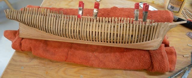
72 The jig is gone! The jig is gone! It is like calling “the British are coming” as Paul Revere rode into the night. I just wanted to celebrate. 1-3 Here are three views. In one we see a towel is the new temporary support Here we are a week or so later. 4 here we see the main framing of the cabin coming together. I need to think more about the size of the frames. Since there are no cross beams at the deck level, connecting the shear planks, and because there is no outside walkway going by the cabin, whose framing would have formed a truss, what to do? As I wrote in an early post this design was an issue as it was an unorthodox build. My current solution extends the full size frame up to receive the cross beams. now they are all in I would add knees below them and perhaps a shelf too. Thus the rigid square roof deck of the cabin, supported by four full size frames, is the structure that holds the vessel together. I will cut down the intermediate frames a little for the mid span and more for the quarter spans. In the painting, there are white painted side planks and very small portholes, not windows in the siding. Those little portholes suggest the idea, to me at least, that the structure goes up and across, and that is what I am trying to show. much to do and we had our first snow last night. At least that means no more yard work to interfere. cheers 5 here we see the upper planking. I have put the bulwark planking on to mark and rough sand the stanchions. I am still moving on with the cedar at this point. 6 here I have tapered the stanchions. now fine sanding to clean it up and fix some damage as I used the Dremel to rough sand and over cut in a few places. 7 this shot is the bow on view. Here one can see the opportunity for some diorama action one day. Next up is another plank and the main rail then to do the other side, complete the cabin frame and a little decking, lots to fine sanding and clean up before oil.
-
Thank You Wefalck I am of the same thought. As I researched the history of the local yard I learned that Hodgdon ran the mill. heck Hodgdon Mill was the name of the village until 1880 something. He also bought up woodlots up the Damariscotta River [ other side in Bristol Me.] and brought in much of the lumber from the local area. I used the Costello as it is fine golden grain and looks a bit like Oak. When I photographed the rebuild of Ernestina Morrissey they used the Dutch Oak and it was golden color just like the Costello. The red cedar was everywhere locally and gave some protection against the moisture. Today it is still used on premium wooden hulls I am more interested in trying to get things like the material representation authentic when I can. For me to have damages in the planking is something I am OK with, so I plan to let it be. cheers, thanks fro dropping in and happy holidays
-
71 how many sails and how much planking In this brief update I am confirming the plan for the additional fore sail on the small half brig. 1 here is Albert with the same sails as the Kate Cory whaler. I can understand for a slow whaling operation to avoid another fore sail. 2 here I have hung a potential third foresail. I like it. This vessel was a merchant likely sailing to the Caribbean and back. Most visuals are of bigger vessels say 20 feet longer and they all seem to have four sails. We only have another head stay, so let’s go put the third sail on. 3 ta da. All sails now on 4 now I need to add more pins. Oh well. There never seems to be enough places to tie lines. As to how much planking I am not sure there is any right or wrong. This is no admiralty quality build but a simple representation of a local vessel. For the bottom area I think I will continue to add planking more on one side than the other. Thus, one can see some frames and the backside of the ceiling on one side and the unpainted planking on the other. 5 Here the starboard side is planked enough to show the tie in with the transom. I think I will leave off much of the planks on the port side. An issue is look at the many damages!!! One thing I have learned is to regret the decision to use the soft red cedar on this small-scale application. I have built 6 hulls between 42 inch and 5 plus feet meant for RC sailing. In those builds I used 1/8” plus thick cedar strips. They were rough sanded, and resin coated before painting. A very different approach. Two Marblehead racers were left natural, and they are gorgeous. These planks are only 1/16” plus by 1/8”. The edges start off ok but damage so easily. If I were going to paint them, I could fix them. Since this is under construction, many tiny, damaged edges will show. A perfectionist would admit the mistake, remove all the planking, and start over. I am in a quandary over this issue. Since I need to work on another build with a deadline, I may defer this decision. As I write this on this sunny beautiful Friday morning, I am thinking I should change materials for the topsides, and maybe even remove the transom planking. I need to think about a better material. I would rather not use the Costello, yellow cedar or poplar as they are already other elements. I must first wait for the next rainy day and think again. I like the look of the cedar and its use survives today......was it used back then?? Cheers
-
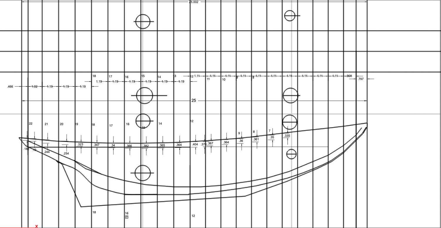
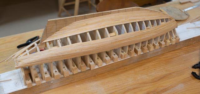
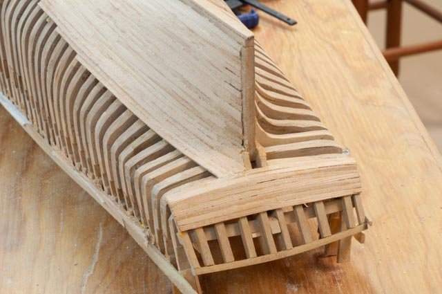
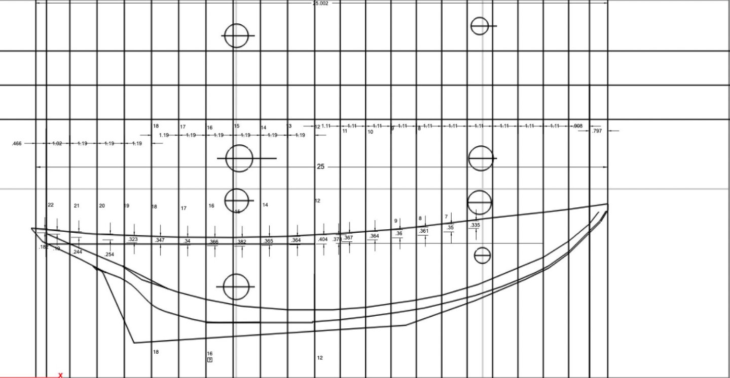
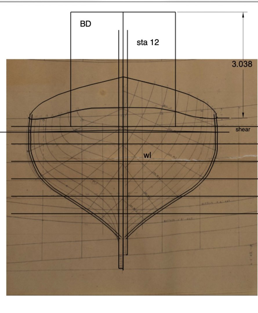
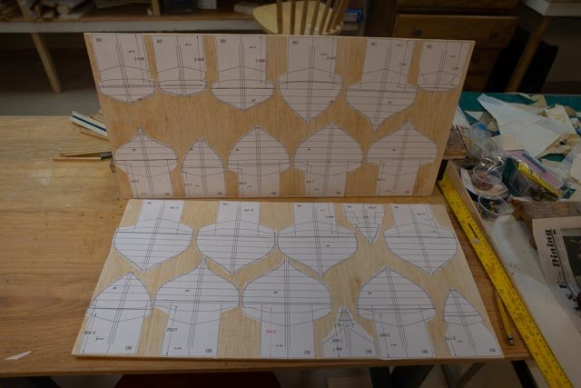
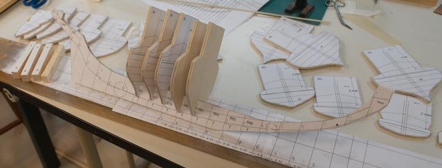
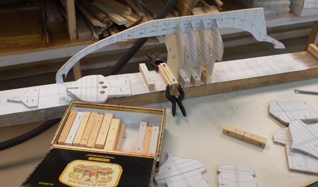
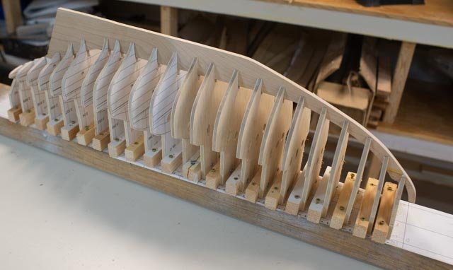
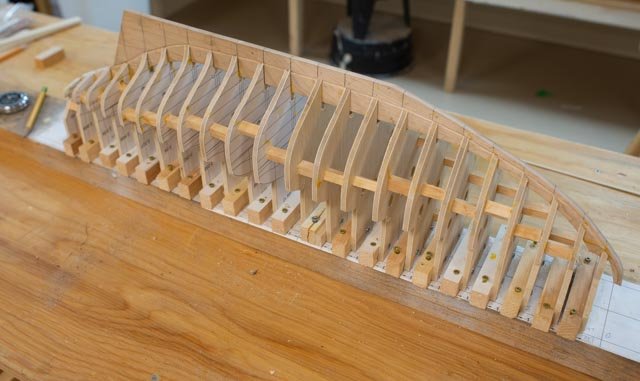
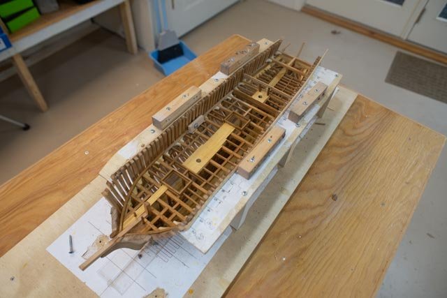
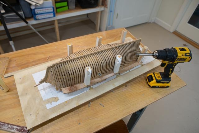
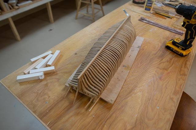
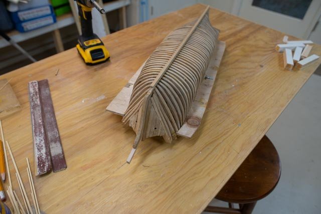
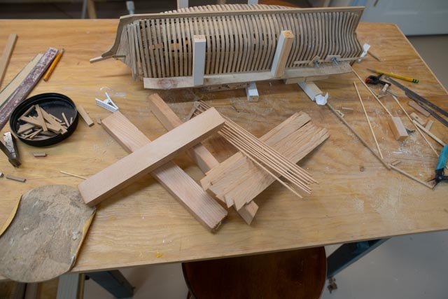
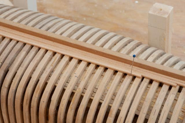
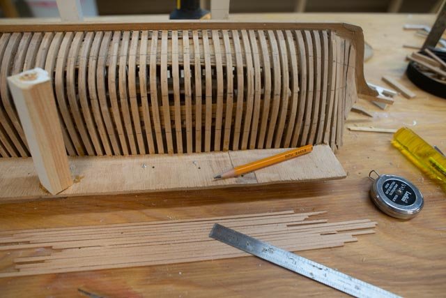
02 pre work There is a lot to do before this build can take over the shop. The biggest item is getting the build H G Berry, two Boothbay half brigs before it out of the way. Looking forward, the first thing to me is to plan out the build board and bulkhead strategy and the start to prepare material for them and the hull. 1. here I have a rough draft of what will become the pattern for the Keel/ keelson and back bone assembly. As of now I am planning to make this out of maple planks. The upper half of the drawing is made by extending the station lines and adding centerlines for the pattern to be glued to the build board. That way I am not remeasuring stations twice. The main prework is to make all the station bulk heads. 2. Here I have developed the standard for the stations to be cut out and set on the building board. This is one of 22 stations with the embedded photo from David Nutt’s plan of the lines behind. The double outer line is to account for trimming the planking dimension. 3. Here I have printed out all the stations and spread them out on a sheet of ¼ plywood. I had to buy it yesterday, as what I had left over was a bit warped. I think after getting another piece of maple for the keelson that for the most part I have enough material around to make the hull. 4. So here we are with all stations glued on and cut out. I then need to get the slot right for fitting the keelson assembly 5. Here I have rescued a past used building board. I have cleaned it up and glued down the pattern for laying out the frame. I also made up the blocks as reusing them proved not to be a good approach. So next up I cut out and sanded down all the 22 station bulkheads. I also made lots of blocking. 6. Here all the bulkheads are in, the keelson assembly is trimmed to conform, and the rabbet cut out 7. Here from the stern we see that patterns on the forward frame is visible so after fairing the bulkheads, the lines should survive…..a little hope here. I also learned to make the blocking soft wood and small enough to both hold a clamp while planking and able to be cut out later. 8. Here from forward we see the patterns on the forward side of the aft bulkheads which again are intended to survive fairing. In both cases I made the bulkheads 1/16” smaller than the lines to accommodate planking. This update means as of early December we are making sawdust. Next up will be to fair all bulkheads out, select material and mill out planking and get going on that process.
-
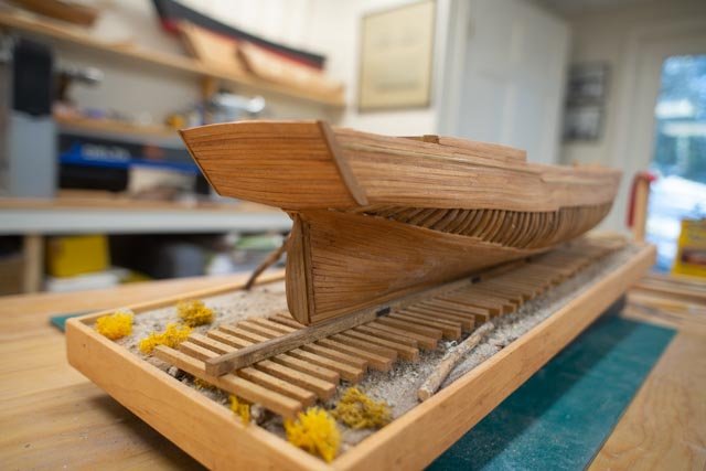
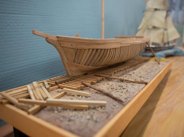
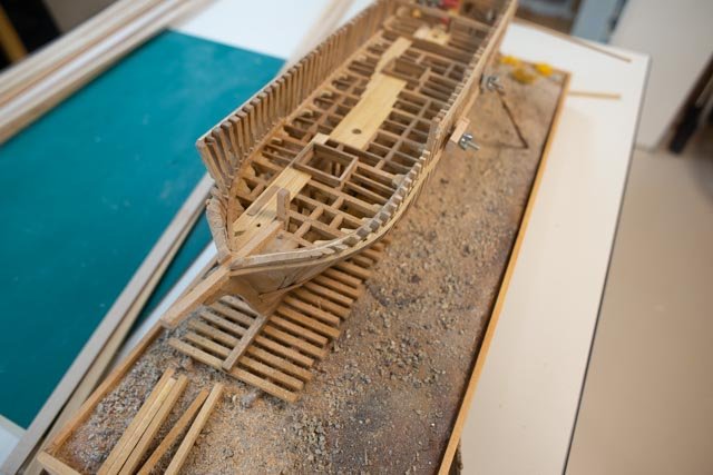
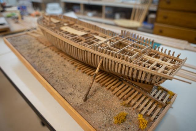
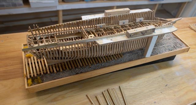
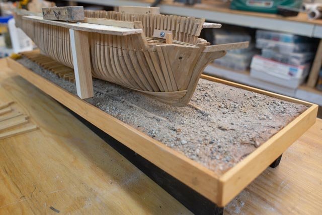
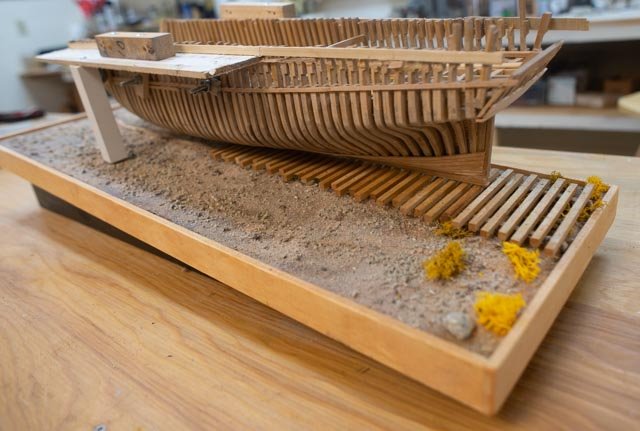
70 thanksgiving update this update shows a little progress on the different areas as we try to close in on determining how much more we can do before the next build takes over.__ small half brig Albert 1. the upper main stay sail is in place 2 the main topmast staysail is in place The large half brig H B Berry 3 I starting planking on the hull 4 I completed the stern framing and will begin partial planking here too. 5 starting to make a compromise stand. i use spackle as underbase and gather fallen sticks for the timbers. 6 here is the base under paint on the spackle with main way logs in place and planed 7 here I have added main coat of sand and gravel with a little sawdust etc., and I have started to set the railway cross ties. For fun I set the hull on top. 8 bow view. Here I will have more planking on the starboard side. I have started cutting the frames above the shear planks. I am still figuring that process out and have oreder sam small cutters to try to improve the process. 9 in this stern view we see the railway is off center. This placement gives us the opportunity, at a later date, to add in some building detail like a ramp, or a gin pole or some type of activity. All for now
-
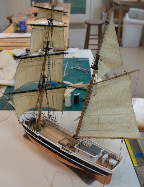
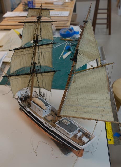
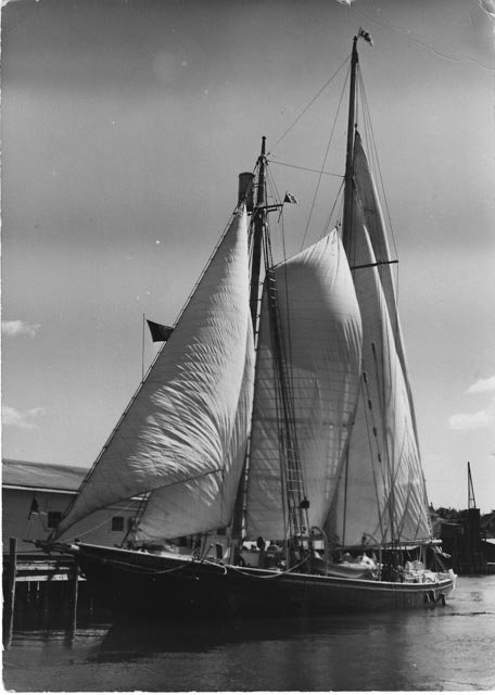
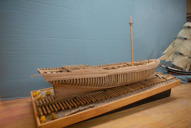
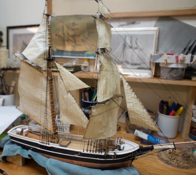
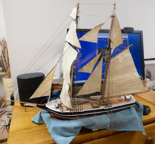
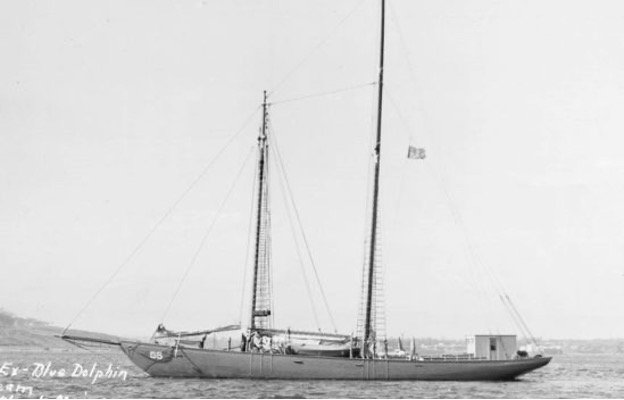
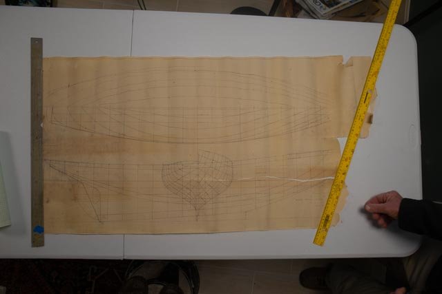
The Schooner Blue Dolphin BD 01. The Beginning I start this new log with a little nervous excitement. Fortunately, it is only 'father time' making it scary. The story of the Blue Dolphin I am finding is quite interesting, but my knowing a principal character in this play and having the possibility of meeting more of them is really exciting. The big fear for me is the short deadline to prepare for a conference next June to celebrate the three schooners that combine both Boothbay Harbor, Maine, and Arctic Explorations in their history. First at the highest level let me offer the plan for the panel discussion next summer. There were three schooners that fit the bill. The first was Bowdoin. She was built here in 1921 and returned many times while leaving for or returning from the far north. She was recently replanked here in 2018-19. While here I got to climb all over her with Will McLean her captain and I built a diorama depicting her in Greenland in the spring of 1924. In more recent times, she sails here most every year, normally for the same Windjammer week that would include our panel discussion. The second was Ernestina Morrissey. There are many connections of people that will come out as we tell this story. In short, her long history included many seasons sailing in Greenland especially 1935- 1940 when a local summer resident / college student was on her every summer. She came to Boothbay again in 2015 to be completely rebuilt. I had the fortune to climb through her many times and meet the crew that did the work. I built another diorama depicting her in her 2021 rebuild. The third will be Blue Dolphin. The connecting history is the owner who bought her in 1949 and led scientific expeditions from Boothbay to the arctic from 1949 to about 1954. The owner and captain David C Nutt Sr had sailed on Effie Morrissey, was the executive officer on Bowdoin in her early WWII days, and then captained the Blue Dolphin. His son still lives here and has many memories to share. I will be building a model of her in the same 1:48 scale of the other two, to present as part of the panel event next June. Ah then JUNE!!!! … the downside of this venture … That means I need to get to work right away. I need to put down or at least drastically slow down the build I am doing now and jump into this build with only 5 months to do the work. Blue Dolphin brief History So first let’s look a little more at Blue Dolphin and see what we must do. What do we know, and where are plans and photos? She was designed by William Roue and built in Shelbourne, Nova Scotia in 1926. Mr. Stephen H Velie Jr of Kansas City retained William Roue, the architect of the well-known 1921 schooner Bluenose. The charge was to design a 100-foot version of Bluenose to be fit out as a yacht for ocean cruising. The vessel was built in Shelbourne, Nova Scotia in 1926. The owner kept her there until 1933 and reportedly took long trips north. In 1933 Blue Dolphin was sold to Amory Coolidge of Boston. In the first year she was chartered by the Ralph Chandler family, who sailed on a five-month cruise to the Galapagos islands and back. Nina Chandler Murray was a 13-year-old part of that family and in recent years has published a book, The Cruise of the Blue Dolphin detailing their family adventure. ( a fun read) In 1942 the vessel was sold to the navy for $1 and she was assigned to be on station in Casco Bay off Portland Maine. One might recall Bowdoin was similarly taken over by the navy. 1. in this photo we see her with a cabin built around the helm [ Maine winter duty is cold!!!]. The Navy painted her white. She was repainted black when she came to Boothbay after the war. In 1949 Blue Dolphin had been decommissioned and was sold to David C Nutt Sr. , a summer resident of Boothbay Me. David was an active participant in the arctic exploring world and for roughly 5 summers led scientific cruises to the arctic. Records of these cruises are part of Woods Hole Institute archive, Dartmouth College, and other groups. As mentioned above, Captain Nutt had a history that ties together our three schooners who frequented Boothbay Harbor and the arctic. Who was David C Nutt Sr. David C. Nutt Sr. as a student at Dartmouth College sailed every summer on Effie Morrissey, now Ernestina Morrisey, with Captain Bob Bartlett from 1935 to 1940. David is mentioned several times in the history of the Effie Morrisey and fondly remembered by Bob Bartlett the well know skipper. Bowdoin. David Nutt Sr became the U S Navy exec. officer on board Bowdoin during her early WWII days. They were surveying to find the best airbase locations in Greenland. David left after completing that mission and went to the pacific to continue ocean surveying as part of the Pacific campaign. When he returned, he found Bowdoin committed to return to Capt. Donald MacMillan and Blue Dolphin available. After buying her, Blue Dolphin came to sail out of Boothbay in 1949. After 5 years of northern cruises, she stayed in the harbor until the early 1970’s. She was then sold and moved to the great lakes. More on that story later. Where to get drawings???? David Nutt Jr. is a neighbor and friend of several years. David was a professional boat builder. One of his joys after selling his business, and by the way sailing for four years around the world with his whole family, was restoration of classic racing sailboats. David restored my Boothbay Harbor One design, a 1941 classic 21-foot beauty. More on the story in my BHOD log for the two 42-inch RC models I built a few years ago. There were many views of his work included in that log. I contacted David a few months ago when the possibility if this schooner project came up. David owns, and kindly shared with me last week, an old print of the lines of Blue Dolphin. He also built a Half model years ago. The black paint on the hull is the same as on the real schooner. 2. David Nutt sharing his old print of Blue Dolphin 3 David Nutt’s Half model of Blue Dolphin he built many years ago. So, with about 25 photos so far from the internet and the local Boothbay Region Historical Society along with these plans, we are ready to begin. First up I embedded the squared-up photograph in my 2D cad. David said he has many more on deck photos and we hope to get to see them this winter. My intent would be to try to depict the 1950 sailing version as it applies to our town. Much to do to get ready

-
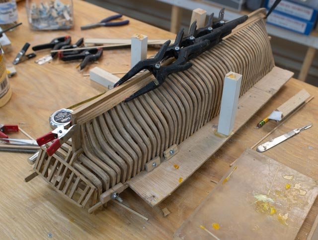
69 H G Berry comes out of the jig. Yippee. As I said in my last post, I need to focus on having a plan to manage my time, so I can get this model to a respectable point as I transit to the next schooner with its tough deadline. To complete the large brig, I must get to a minimal condition before I can set it aside to build the next schooner. current status: • Insides below deck is basically done. It needs more cleaning and oil. • Framing to the deck mostly complete. I need a few more waterways after the stern members have been completed. I then need to cut one side of each frame very carefully just above it, so I can then build the shear plank inboard and outboard. Then shape the stanchions and build up the bulwarks to the rail. I am very worried about this procedure as the frames are glued and the glue maybe stronger than the wood. • Planking. I will do perhaps the first inch or so covering where the ceiling already is in place. I may then have the shear planks and bulwark in place and then add some upper planks. I am also still debating on material. See below red cedar. • On deck….I plan to build the framing for the two cabins as soon as I get planks on. That should be it. • Stand and display…. many options for now. Unfortunately, I am likely to defer on the shipyard and use a simple board for now as there is not enough time left in the year. Here are visuals of coming out of the jig and planning the planking: 1 first up is to remove two more legs and screw them on top for supporting all when it's upside down 2 Here we turn over the jig and unscrew the remaining legs 3 ta da here we are free at last 4 the legs come on and come off and move when needed. In this view I can finally see enough of the stern area that I can figure out how to build it 5 here we see the bow I will first go over the whole thing with a sander to get the frames faired as best that I can Planking 6 I built a stair to the back deck this summer and have lots of red cedar cut offs. I cut them up to make model rough stock. Here I have next milled 3/32 + a hair thick stock and then sliced it off using a 5/64 stock that I bought for the yellow cedar ceiling planks as a guide. This gets me more that 4 inch thick in scale and allows a little sanding. 7 here I have laid a few planks to see the color and overall look. I like the color. I also like the fact that even today eastern Maine red cedar is a material of choice for planking lobster boats. I would accept criticism re the slight visible grain that blows the scale. Anyway, I used it in thicker pieces for my RC hulls and like the feel of it. 8 here I laid out the three battens [ just pencil marks for now]. The largest width works out to be 14 planks for each zone. The tapering for the bow is about 5/6. I plan to lightly sand as I go 9 here I took the first two sections of waterway and cut one of the two frames to leave behind the stanchions. I then laid out the planks that will go right under the shear plank and determined cutting one plank to a square will perfectly fit for the transition to the higher bow and stern decks. [just to the right of the blue tape] well... there are many weeks of work here......I need to get going. cheers
-
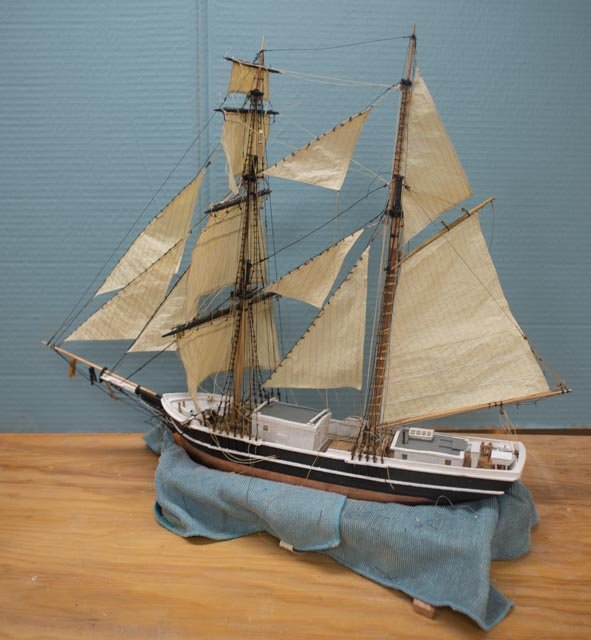
68 general updates on two brigs and then Albert sails As we move toward winter, I need start managing my time. I had a new project in mind to follow this one and thought that sometime in the winter I would wrap this one up and start that one…..oops!...... After discussing the plan to combine a new schooner model with two others, the Bowdoin and Ernestina that I-built a few years back, and then prepare and tell part of the story of three arctic schooners from Boothbay, I just got pressured to have it designed and built and then with a research paper present all next June. I will talk about it in the beginning of its log but just want to say ouch. I am researching for it now and have started its drawings. I will open the new long next month, but want to get this one closer to the endzone. For now, I need to carry on and get these brigs as far along as I can. They do not have a deadline but it would be nice to get them presentable. I should be able to complete the small one as I am into rigging. The framed model completion will depend on how far I go and whether I simply set it on a board or try to build a shipyard around it as I did with two past models. More on that decision as we get there. To complete the small brig, I need to do the following: • Complete and bend 6 sails. Two more are now in place and tied off, so four to go • Make and set coils on lines…..started but little progress. There are about 80 to do. • Complete standing rigging. Just a few more shrouds and ratlines on the main mast and repairs for the head stays • Set cabins after lines are all done. Simple when ready. • Build two small boats. This item may get deferred until I am building small boats for the next schooner. • Build stand. I must decide what to do. I like making ocean with a hole for my sailing models. The cost of acrylic however has skyrocketed, so I am passing on that approach for now. More to think about Here are a few visuals of Albert 1 Here we see the next two sails, 2 of the 3 main staysails, bent on the small half brig 2 Here we see in the painting of Torrent that is the 112-foot 320 ton version that sports four head sails. The whaler plans for Kate Cory only showed two. I have decided to add a third head sail. Many of the images I have seen od half brigs show three and I prefer it. The only other Boothbay sailing image I have is Havana at almost 220 tons vs 123 on our small Albert; she had four as well. I think adding the third makes sense of proportion on the smaller sized vessel. 3 Here I quickly took the lines and roughed out some small poplar stands. I am dry fitting them on the spare hull. These will make up a temporary stand, so that I can move on. Cheers
-
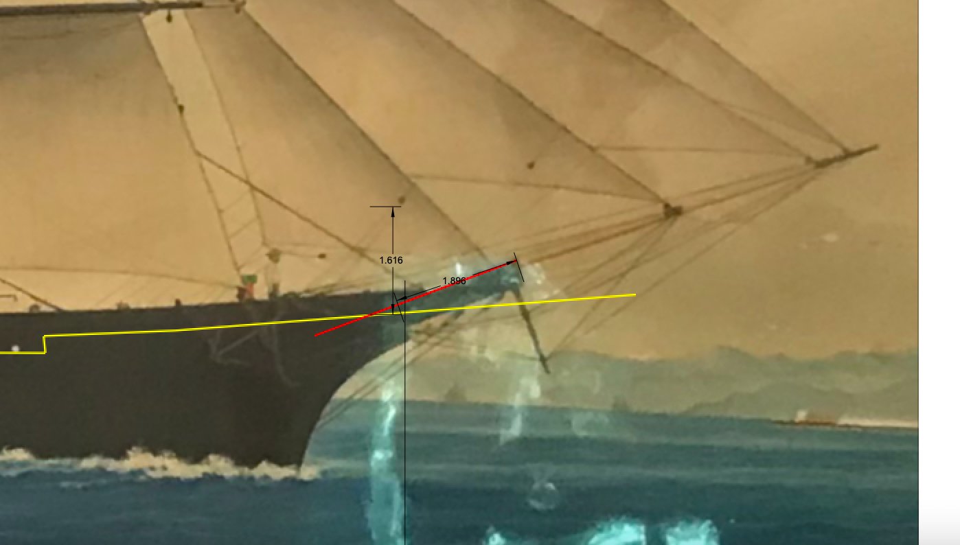
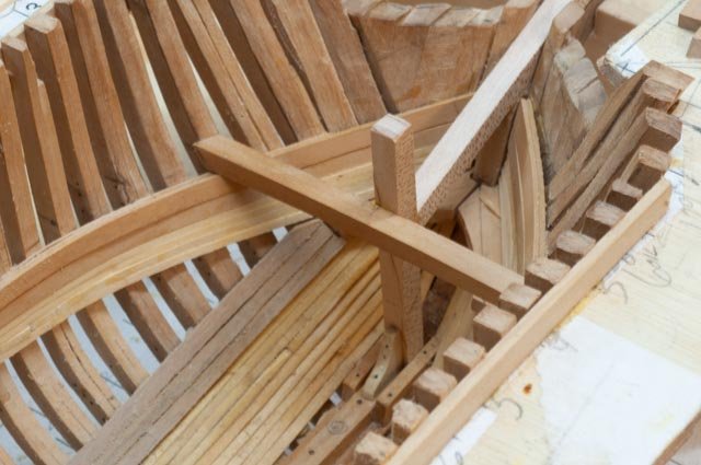
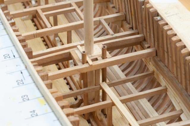
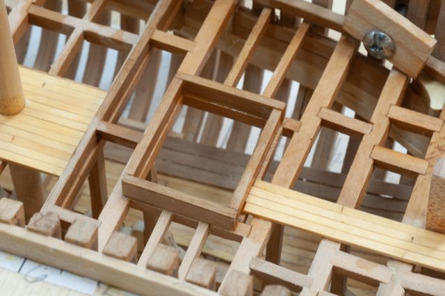
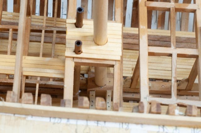
67 completing deck framing on HG Berry At some point, I need to turn over the hull and get the outside faired and some critical planking on. I believe with the deck frame in place and both the shelves and waterways glued, I should be ok. I would hate to get too far and then lose some of the detailed frame yet is it is so easy to just keep going. Today we are looking at what I would like to complete. Before moving on. First a few details 1 Here is a detail of the bowsprit coming aboard and hitting the Samson post. Based on the angle taken from the painting as I discussed earlier this happens just below the deck level. the framing al came together. I want to be sure most of it is seeable once the deck is on. 2 here we see the detail of the log pump. I posted a query on the deck furniture forum to see if anyone knew more about them. No one has yet responded. In a search in that forum I found one person knew they were indeed hollowed out logs and often elm. We definitely had elm trees here, so maybe that was it. Oh well onward 3 sizing the hatches is a bit of a guess. 4 I love the view through all to see the mast step. I have the dowel in place and left it there on my last diorama. 5 here is my day of producing a myriad of knees. I a making 40 to cover the main beam connections. I hope it works out Now overview and planning what to do before turning over 6. the foredeck. I think I am complete here for this phase. The waterway is being glued.I started adding tung oil and find it a great improvement. The framing across the anchor chain hawse will be drilled out after turning over. I drilled through the hull then added the deck fill in, but cannot get the drill between the build board and the hull to drill back up and in. I will also do something for the windless framing once the outside work is done 7. this shot is before knees and waterways are in place. I need them before flipping. I also need to decide what I am going to do for the transition of frame to stanchion above the waterway. I hope I will be able to cut them down. I found on Schooners the stanchion was added to the side of the frames , so this will be a new challenge for me. 8 work on the aft cabin will continue to complete the forward bulkhead. I started the cabin top frames, but they are delicate and may better wait. 9 The stern, transom et al. I have looked into these many times. I think I will have an easier time once I turn things over and then can see it from both sides. The frames need a lot of fairing and doing some of that first should help with aligning what is affectively one of maybe two more split frames. I made theoretical mid frames, but they just don’t look right. I did figure it out on a schooner once, so I hope I do this one too. Carving a block for a plank on bulkhead is a dream. Thank goodness it will be on my next build. All for now. time to blow leaves off the yard.
-
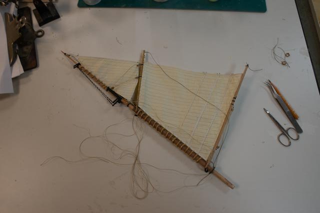
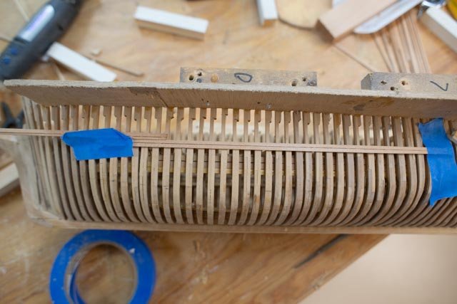
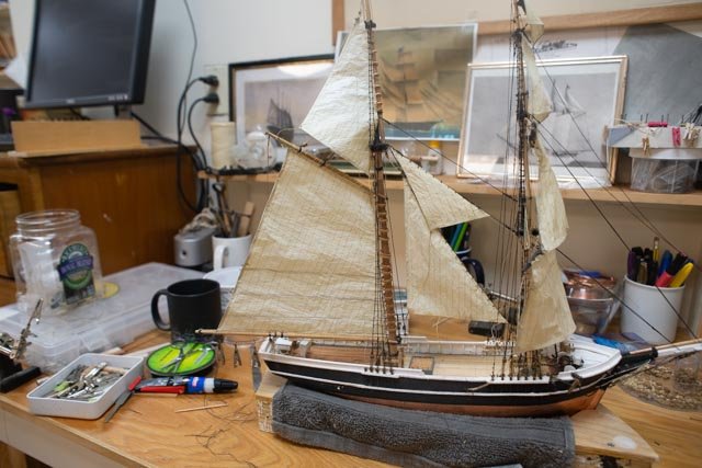
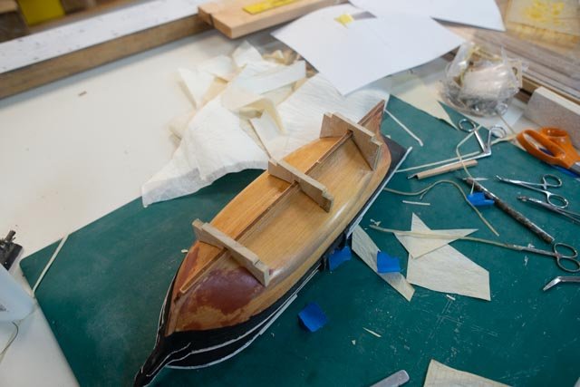
66 let’s get the spanker bent and main mast set on Albert I mentioned before that I prefer to sew sails to hoops and connect most running lines while the sail is resting on a flat surface. I learned that while making much bigger RC sails, but feel it is quite useful when working with the fragile silk screen. Here are a few shots of that process. 1. here is the set up. I first lash sail to the boom and gaff. I then add the parrales to the jaws to hold all in place. I then carefully sew the sail to each hoop. There is a string run up the luff to reinforce the edge of the sail. A wire is along the leech, and sting is on both head and foot. 2. Here the spanker and the main topsail are in place and most of the loose lines are connected. 3. Here I literally just set the mast in place. Note the cabins are off to make rigging easier. The aft cabin shows the clearance under the boom. is OK 4. Here is a progress shot with most of the lines dropped to their correct area and the fore cabin set and mock up boat. 5. Now we see what a half brig is all about. Half brig and half schooner. All for today