-
Posts
856 -
Joined
-
Last visited
Content Type
Profiles
Forums
Gallery
Events
Everything posted by Jond
-
Thanks Patrick I appreciate your taking the time to follow and comment. I had to laugh today as I completed the rope and rings for the jib and realized it is on the port side. I thought about it and said to myself....perhaps while adding a load of lumber they had a left handed sail maker replace the jib while in port. I am going to work out side this afternoon cheers
-
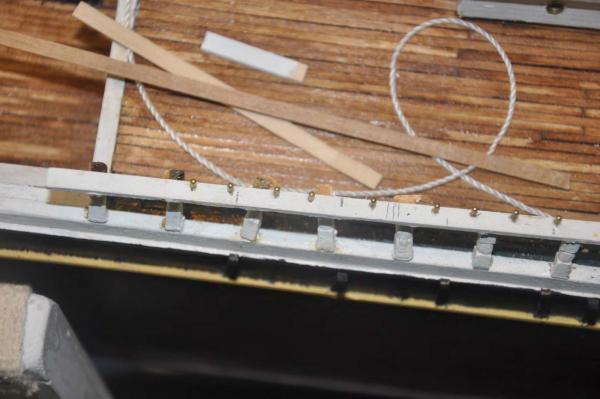
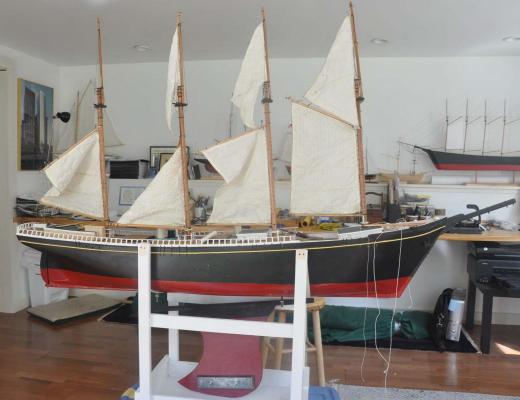
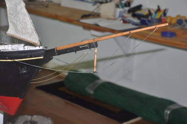
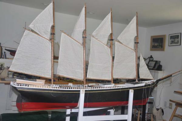
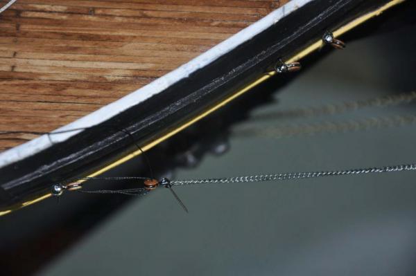
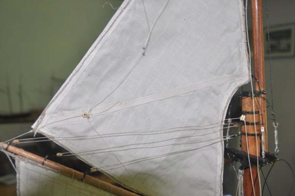
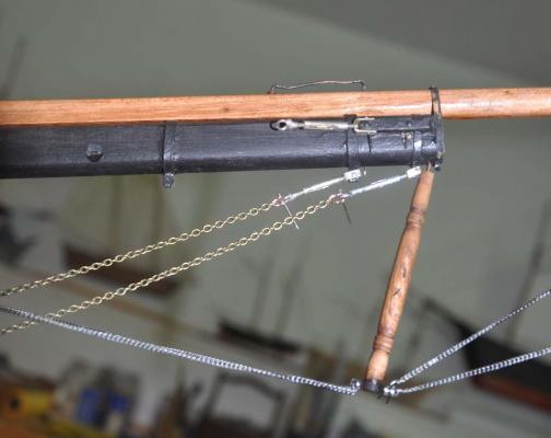
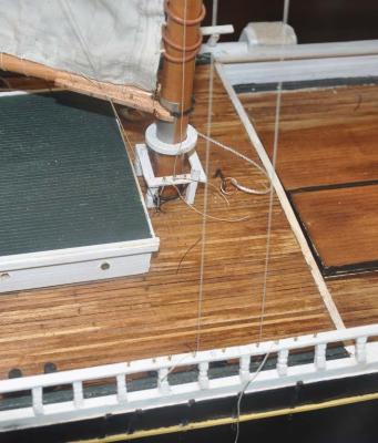
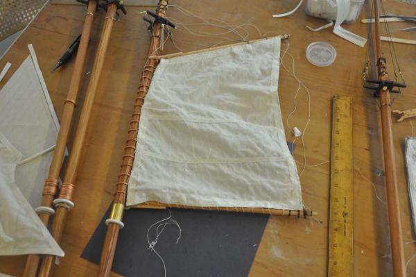
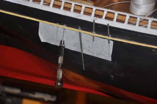
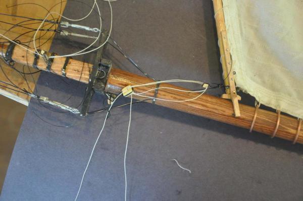
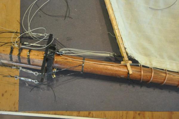
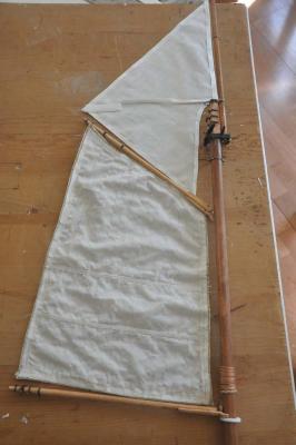
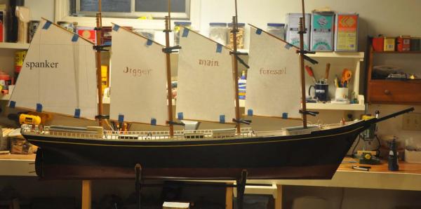
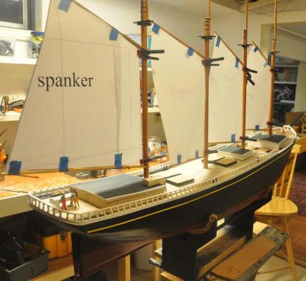
next stage....bend the sails argh. I have found the real dilemma here as I tip toe through new territory. How to build at 1:48 but be rugged enough to sail. examples. While moving the boat in and out of car and in and out of shop for the float test....oops there goes the rail. This oops is without masts even being stepped. . as I tie off blocks for halyards, I kept pulling them off. I changed two of the throat halyards triple blocks to wire staples up through the cross beam and bent over. A little over kill. I left the others thread as they did not break....yet Yes I am using thread...not lines. mostly 70% poly and 30% cotton from Joann. I bought better for stays. There is also no way I have a vehicle that can move this boat. I do have a small boat trailer for my 12 foot sailing dinghy but really. I will need a friend with a pick up hopefully with a cover As I go forward I smile and remind myself of my goals. I want a 1:48 scale schooner in most things. I want every line that functions. Yes the major sails' sheets are a little big, but so far that is all. I just need to to do my best and get in the water. If I can build it, I am sure I can fix it, so here we go setting the sails bent. I have moved the boat to my study.....only about 10 feet away from the shop. It has nice daylight and overhead task lights that help with vision. I can work on all sides, and using the strapped stand I can also tilt either way for port or starboard tack. That way gravity helps move the sails out of the way if I need to see the deck etc. here we are starting the process. most of the work was done off board to sew the lower sails in place and trim the spars. The stay sails are held by jack stays and are done in place. before we can work forward I needed to trim out the bowsprit and jib boom details I found from the details on the CORA CRESSY plans on all block sizes, chains and lines. The light chains were either 3/4 or 7/8 and like the stays us lashing with dead eyes. i used light wire to make all the strops with shackle connections for pinning to eye bolts. the larger chains get turn buckles. This was fun for me. After turning the martingale I had to do more real soldering. The bottom cap needed a double band forward and single aft.. I also fully soldered the band holding the jib boom down to the end of the bowsprit. It worked but boy I am really new at this task. I used 24 gauge copper for the shackles and painted the chain in place to get it to look like galvanized chain. The turn buckles are a bit shorter, and the two unconnected ones needed longer clevises to allow pinning to the bees. I held up on installing their chains until I run the upper stays that hook to the sides of the martingale and run to the prepared lashing dead eyes. I just want to hand fit the line of the chain and then drill the eye bolts....yes i am chicken finally here is the attached foresail. It's a big milestone for me. The sails are threaded up the stay that you can see is lashed to the staple forward of the bitt. I found a new problem with the top sails. they each have clew lines that raise the clew up and over the brace stays [ not yet installed]. they are like the tack lines [ also up and over the brace stay] and sheets that run either to port or starboard pins. All three sets have one loose to leeward and one tight to windward. For RC schooners the stay-sail rides with the gaff and is like an extension to the lower sail. [ I shall add little lines for that function too] Thus these lines can never be tight; what to do. here you can see the clew lines that run from tack up through the the block held through ridge line boss ring through the sail [ see picture] and then further through a lizard to the peak block and down. here you see the three attachments for each side. the two lines on the side rail are peak halyard and clew line. the two lines at the mast rail are sheet through the leader block aft and the tack to the middle pin. My plan is to run the tack and sheets continuous through the rings and then leave a bit loose. the clew must just be loose because there are separate peak blocks. After sailing is over I can tighten them up. here one can see the tight fit for lines where the lower main deck carries the leader blocks for the foremast beside the forward deck house. I believe using the Bluejacket pre-stropped blocks makes this doable and rugged. finally here we are for progress.... 9 sails on and 6 more to go cheers
-
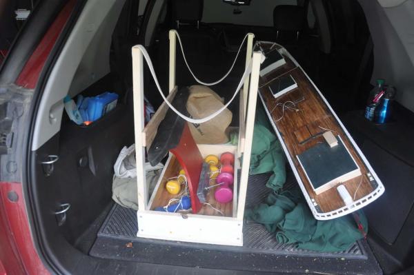
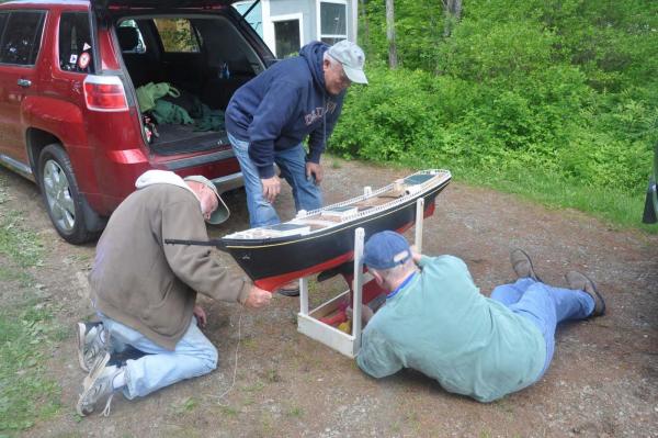
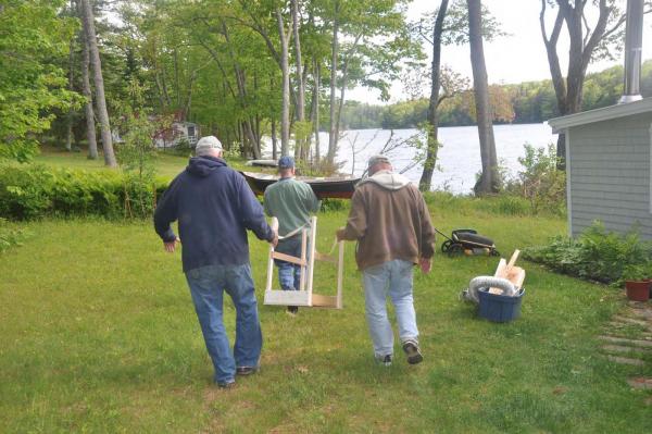
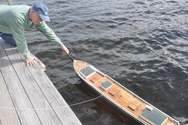
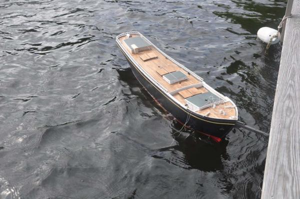
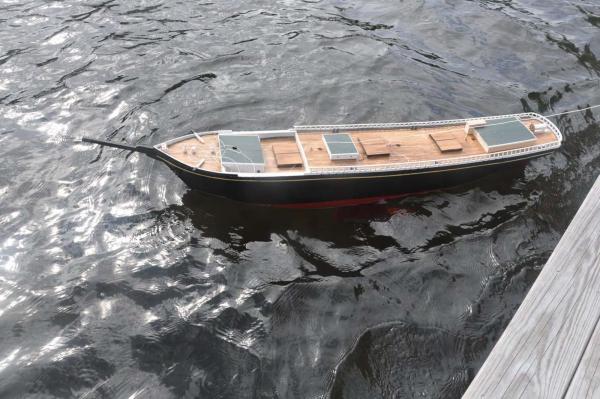
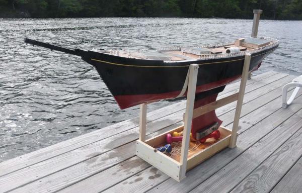
We we had a great first launch and float test. I asked a friend to use their fresh water lake site for this first test and it worked out just great. here we are loaded into the car. Unfortunately this won't happen with the stepped masts and I am working on that problem. The stand carries the weighted keel and several weights if I want to try increasing ballast to get lower into the water. here we are attaching the sailing keel. it was easy to lift and carry a few hundred feet to the lake front dock. The combined weight is about 28# it takes two people to launch and comments were of concern as what to hold onto. I need to consider some easy to hook on launch lines. today there is a little wind and rip of a few inches. Looking at the action along the waterline I was very happy where at rest the waterline is about 1/2 to 3/4 above the water. this is safe for saltwater harbor sailing. turning away from the dock into the wind, the waves came above the waterline, so I think the current weight is fine. I believe adding the masts and batteries etc are another pound or so and that should be fine. here we are at rest after about 10 minutes. Inside was dry as a bone, so all is good wow what fun
-
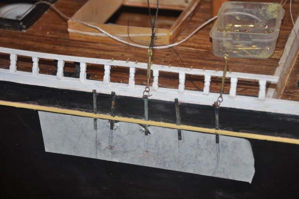
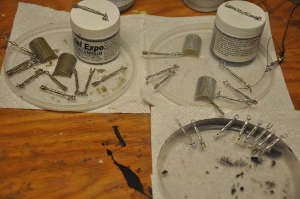
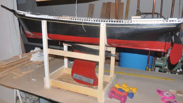
Maine spring is quick and fickle. We hit a new record low yesterday 42. Anyway I need to get ready for a float test Friday so I have made progress in several areas. Sails rigging and masts For sails I simply need to continue chipping away so when the hull is ready I can put in complete masts and rig up the running rigging right away. I remain unhappy about puckering but sais le vis as I complete sails and get them sewn onto the spars I need to start the running rigging. as i said last time I take the machine sewn sails upstairs so I can work on them off hours. I find early morning works best and those in the photo are all done now. after much consideration, I now believe proper blocks would have been galvanized metal straps and oily,dark and almost black wood. As on other models for economics I have used the inexpensive bass or walnut made blocks they dont look like galvanized! I started with them and found another problem. pre-made blocks stop at triples and they are too delicate to add beckets. These schooners actually used quads with a single drop to the deck because they used engines to raise the sails. Gloucester and similar schooners had lines coming down port and starboard out of the top block and bottom. They had one direct to get close and then a whip on the opposite side with double or more blocks as needed to get it tightened up or trimmed. For this first go i decided to put triple up and double down as that what was available. I did not like this solution I started to install all of the belaying pins and deck staples. These staples mostly take stropped blocks to receive sheets that go up to pins on the rail. The open main deck has seven blocks on each side that will be very difficult to install in the narrow area beside the fore cabin. So after much thought, I decided to bight the bullet I went to Bluejacket and bought their beautiful stopped blocks all with beckets. This allowed me to correctly rig the gaffs with the becket above and triples top and bottom. yes they should be quads but I don't see any in the market at 1/4 inch. I chose black to paint out the 'wood part' leaving the side strop, sheaves and tabs galvanized. I installed all of the chain plates and have repainted this after the photo. I dry fit a turn buckle and continue the long production. After asking on this forum for feedback the responses i got were for paint as the standard galvanized solution. Model expo had a 50% sale, so I bought one each aluminum and silver paint to try them out on brass. They are very close. I like the aluminum, as there is a little more warmth to it and slightly less shine. I plan to use both. To get ready for the float test, I needed to get some more lead. amazing, I looked on the web about 3 PM Friday and ordered 20# for normal shipping.....it arrived Monday wow. I completed the sailing keel; painted it out like the hull and added two 5 pound weights as a start. Here is the hull with its new smooth bottom [ I used gloss paint to see the look and I don't like it...next coat back to satin fiesta red which is more like brick red and perhaps red lead. I made up the strapped stand that holds the weighted sailing keel under the hull. when ready it lifts up and bolts to the hull and I can lift both out and head for the water. I have several hand weights in 2 or 3 pound to use to trim. the current hull is 15#
-
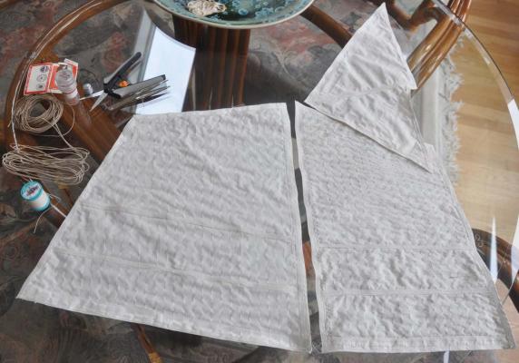
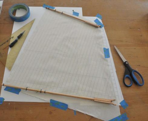
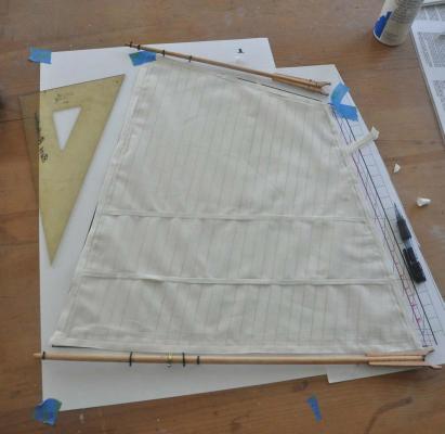
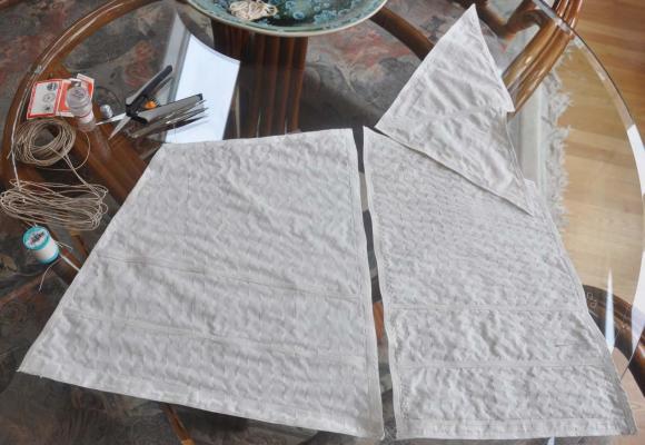
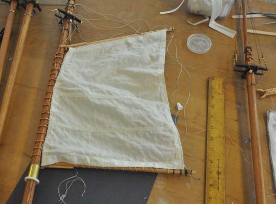
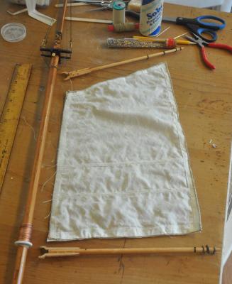
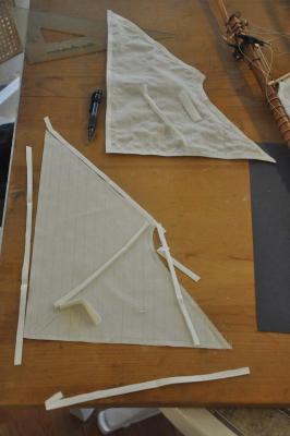
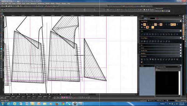
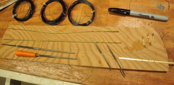
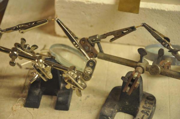
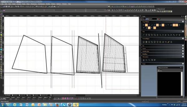
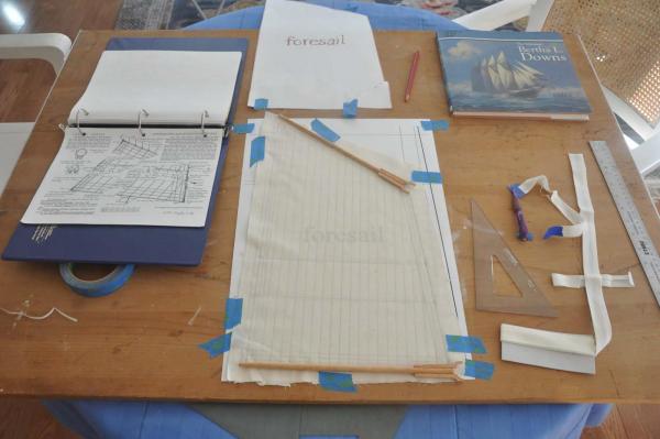
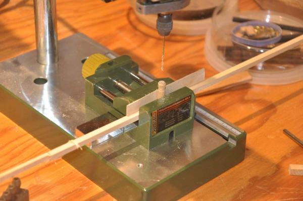
Well I am finely back at it. Spring clean up does take away lots of our time! I am now focused on production in two areas, sails and fittings/ turnbuckles as well as general progress on the hull, spars and deck Sails: I continued the trial and error process and made all four sails. I then decided that three of them are for the trash bin. The best approach to the puckering I found is to stretch the cloth while sewing the seems. I learned to tolerate reality when I remade the spanker. It was my best sail yet and looked great with very little puckering. I set it on the table ready for applying the rope etc., and after one night it looked like all the others. Of well. the color and texture are OK, sailing quality of muslin is likely down a bit I am sure, but I need to move forward. Remember this is a proto type For the production cycle on 16 sails I have decided to do one step on each sail each session, so that I have many activities going on. The list includes, turbo cad drawing and trial design of each new sail; layout and marking for first machine sewing; gluing and machine sewing bands; hand sewing the rope and rings; hand sewing to the mast and spars. Here I am laying out the spanker Here I have glued on all the bands [ bias tape]. I since learned it is better to sew the seems and then add the reef bands over them. Here I took the dimensions from the small scale sail plan and plotted it on my 1:48 plan. It printed it out and actually came pretty close. I did have to move the clew a bit forward and raise the tack. Here I took the completed new foresail, laid it out and placed the cut out gaff topsail to trial fit before machine sewing. Here I have accumulated a back log of three sails ready for hand sewing on the ropes and rings . I am doing that work upstairs while watching night time TV. The Red Sox , however are not doing very well. Here is the foresail sewn onto the spars. It took some time to go through and trim out the spars. I needed to make the bands, add on the blocks and get everything ready to go. I hope to have each one fully complete before installing. This also gives me more time to work on the hull and deck fittings. Here I am ready to sew the main sail to the mast and spars. note the topmast shrouds are in place. Here I have cut out and have waiting 2 gaff topsails. It is now two steps to sew seems and the add reef bands over the seem lines and machine sew. here each session I need to draw another sail. I have conflicting information on the seem direction for the staysails. I chose the Bertha Brown design with the seems parallel to the luff. I need to add reef bands. Fittings: I mentioned above lots of work making many eye bolts and bands for all the spars. I also taught myself how to blacken as an alternative to paint. I asked for outside advise and found paint is the only likely way to simulate galvanized metal where applicable. It is possible that the change over from dead eyes to turn buckles was coincidental with this schooner. There is in fact a drawing that shows 8 foot chain plates and dead eyes on this early 1894 design. However they would not have been very practical and typically all schooners of this era used turnbuckles and steel cable. Therefore as I have stated before I am using 5 foot chain plates and 4-6 foot turnbuckles as this represents the era. I experimented with using silver paste to connect several 3mm jump rings to the heads of the cap screws. I had beginner's luck, but quickly found my process not giving me the strength. Here I went to the old fashion flux and silver solder process and got a stronger joint, Unfortunately only 2 at a time. for the rest of the turn buckles, I make 4-6 pieces at a time. My small drill press is priceless to drill all these many holes in the 3/16 brass for clevises and the 1/16 brass for spar bands. We all know that drilling brass is tricky and with a hand held dremel would be very difficult. other stuff: I went to our monthly meeting at Downeast Shipmodeler's Guild and learned several things from a real fiberglass expert. As a result I went to the local auto parts store and got Ever glaze finish putty that fills in the pit holes form Bondo and other minor defects. I was also advised to not fear and be rougher on an under sanding. After rougher sanding use the filler putty and get a smother finished hull. The result is learning how to make a better finish and even though that means a step backward, this is be the last real time to do it. I will try to get that done in the next several days. part of the recommendation was to also use auto body filler primer. Unfortunately it only comes spray. I need to go all brushed paint from now on and especially in the future any damage would be repaired by brush. so no filler primer on this model. I will next lay out the 60 ish chain plates and other connections for standing rigging and over 100 belaying pins for running rigging. I have chosen brass 5/16 belay pins as I have so many lines and need to actually connect them. I am not sure if I should paint them silver. I need to think about a float test. the sea water is only up to 50 degrees, and our pond a little warmer. I am thinking the first week in June I should sneak it in to make sure she floats. The lead keel... i really need to get this figured out. I think for this year it will be temp until I really know the right weight. then next winter I can consider to get a nice cast bulb. So there it is. I wish a session was each day but too many other things. I will be lucky to get the sails done in June. I suspect more than that as the weather warms. To get a sail in this year I need to leave a few things out, so I may leave off the top staysails for this first stage. I also want to delay much of the deck detail until next winter. we'll see what make sense.
-

galvanized fittings and chain
Jond replied to Jond's topic in Metal Work, Soldering and Metal Fittings
Thanks for the added advice. I have painted brass chain black for static and found it is OK but not all covering. One needs to thin the paint and then be ready to touch up after installing. I would agree, now that I have tried it, blackening is better. I will look into tinning, but will likely stick to paint as this schooner will get moved around. I like the pencil idea and will try it on both silver and aluminum color. Thanks again...I will comment in my build log after trial and error Cheers -
Carl The abbreviation COE is center of effort. It is the center of area of the sail. It creates a moment force relating to the waterline. Because the sail area of the schooner is similar to the pond yachts it is interesting to notice their moment will be much less. Thus the ability to force the boat to come about (bow crosses the wind to go from starboard to port tack by example) could be a problem. Cheers
-
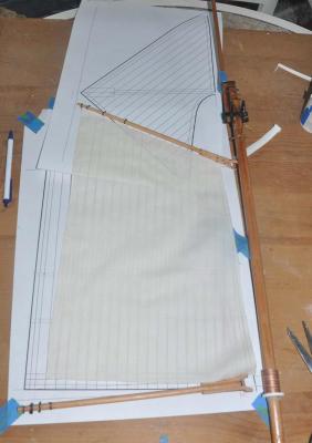
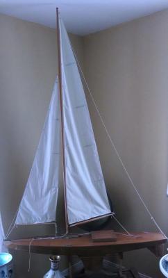
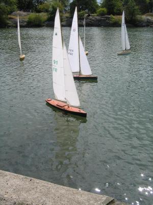
Patrick I am not a RC sailing expert, but as I have followed it along over the years, I have watched several type boats sail. Many discussions come up on hull speed to scale, ability to come about etc. Here are two images of popular and traditional designed pond yachts. This is a recently designed 50 Inch Marblehead class with 76 inch masts and tall [ 70 inch luff] slim sails called the Naskeag. My son and I started one each some 15 years ago and I finished them up last year. They have yet to see the water. This photo is a regata....see how high the sails are with respect to the hull length. The COE scales about 26 inchs above the deck or just > 1/2 hull length. here is a classic 1936 design Gus Lassal that I built 15 years ago. I rebuilt it from copying a broken antique [ that I have partly restored and plan to complete some day] and bought the sail in marblehead, so I could properly size the mast. It was a classic design and its COE is a few inches lower but still not much less than 1/2 the hull length. here you can see the Downeast frieghter with the sail templates .... the lower masts average 22 inches above the deck and COE is roughly half of that . Lets say 11-12" and when I add the upper sails I may gain a few inches. Being generous lets say 15 inches all in above the deck. The decks of the Marblehead and this schooner are similar above the waterline. Therefore we have a similar calc comparison of COE to be 1/4 of the hull length above the deck. So the question is....will I be able to come up into the wind?......we are going to find out .... i sure hope so, or I may have to get a better chase boat.
-

galvanized fittings and chain
Jond replied to Jond's topic in Metal Work, Soldering and Metal Fittings
Thanks guys. What I get is paint is the way to replicate galvanized fittings or chain. Thanks for quick response Jon -
I am trying to build a 1894 schooner. In this Era I find from many photos the turnbuckles ,shackles and chains were galvanized. Moving forward the chain plates were too, but many were painted out with the hull. I am using brass tube and stuff for the turnbuckles. I could use quick blackening to start if that is helpful. Is there anything better than silver paint to get to a likeness of galvanized? Ditto for chain. Most is coated brass I think. Thanks for any help
-

Metal - brass or Ali - turnbuckles
Jond replied to Tallshiptragic's topic in Metal Work, Soldering and Metal Fittings
Anton I need to make 70 plus for a 4 master schooner. I bought 200 cap screws 0 x 90 say 11$ then 3/32 brass tube and 1/16 rod for support while filing. I crimp the cap screws into the tube and the each turn but don't pull out. I then make either ring or clevis. This works for 1:48 scale where I need them to be under 4 feet up top or nearly 5 feet 1.25 inch for the shrouds. If smaller say 1:96 I used 1/16 tube and copper wire glued in or perhaps solder if under any Load. I am still an amateur at this but am researching and thought to share. There are photos on my link. Cheers -
I just used my new found firefox tools to re edit the previous posting regarding turnbuckles and my upcoming search for help regarding options for galvanizing regards jon
-
Lextin I have really enjoyed going through your build. I rechecked in today as I am struggling with sails. When I started my build I mentioned using muslin and you happened to visit my first log and gave me a connection to the supplex group. I have used some newer materials indirectly as I had nylon sails made for my 50 inch marbleheads. they perform well.... they are all about the sailing. anyway I thought you might enjoy my struggles now that I am getting to that stage and still trying to be a traditionalist. cheers jon
- 366 replies
-
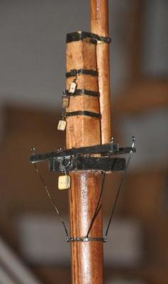
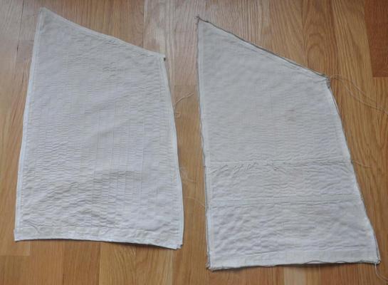
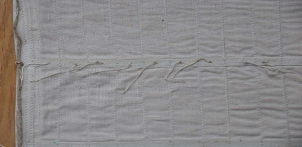
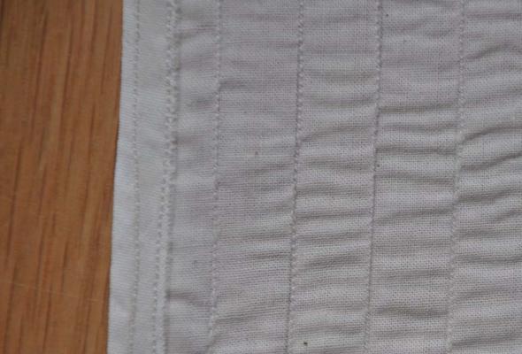
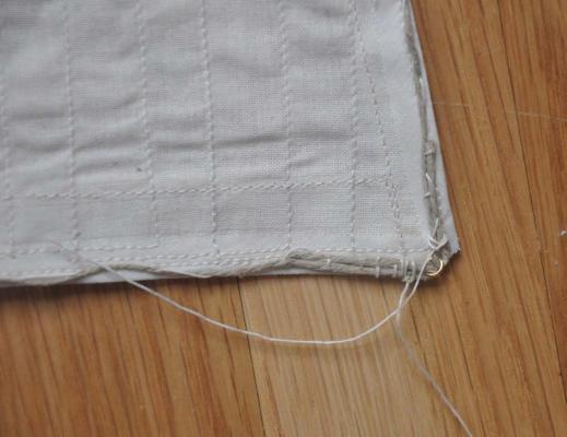
We got back from a week in Arizona to find our Maine spring trying to get under way. This was a short week, but I got a few things done. I got back on the turbo cad and transferred offsets to create a 1:48 set of sail template drawings. I used my wifes' large format printer that actually gets to 13" x19" that allowed one sheet templates for all but the spanker. setting up these templates one can see that pretty though she may be, sailing quality will be a challenge since the centers of effort are so low at the model size. I used details from Douglas Lee that I found interesting. On the starboard side of the standard sail there is a 1 foot liner and the rope and on the port side a 2 foot liner on the leach and luff and what could be a 3 foot liner on the port foot. This two sided lining led me to an old trick I learned by trial and error of taking a 7/8" oyster bias tape and cutting it in half. I then glued it to the edge giving a rough ¼” on the one side and just under ½” on the other. For the sail foot I cut the tape to give me a three foot liner. I also have ¼” bias tape and I fabric glued that for the reef band. Then I got into trouble as I snuck up stairs to sit at the sewing machine. This nice machine is auto set for tension and things, but I can set the length of the stitch. One of the troubles with 1:48 scale is the seams are only ½” apart and puckering is the name of the game. I did the foresail in the standard set of 2mm and it looks like a big lemon was nearby. Today I tried 1.5 MM stitch length on the mainsail. [ my logic of small means less] You really can’t tell until it is too late. I plowed through and got done and was again disappointed. I tried ironing after, but reality is these will not be ironed in place. When I showed my dear wife, she told me that of course a larger stitch and not a smaller one would apply less tension. So the Jigger is next and the first pass will be 2.5 mm or even 3mm. I also may change and reduce the size of the thread, though I am not sure that is relevant if this one ends up as a first attempt and I fix this problem, then I won't mind leaving this one behind this partial main sail will likely become a great rag I also have some jewelry supply hemp string and again I tried to use it for the bolt rope, adding brass jump rings for the four connections and 4 reef points. I am supposed to stop the rope, seizing it at each side of each reef band ring. I am looking for more demerits as I likely will bypass that detail by simply adding the rings at the end of the reef bands for looks. Sail material and advice: I know Lextin said ...use suplex…. And Jerry Todd used it as well in his build, and before this is over I might just do that too. I went to the vendor web site and color was either snow white or what I might say a selection of modern colors. I love the natural color and defects in old fashion muslin when trying to be ugly old canvas. Gluing bias tape to the sides then sewing is easier than fold - glue and sew. it is the seams that I am fighting. Also this boats is to be able to sail, not race. I will show more when I get further into and solve the puckering or give up and go modern. deck and stain As to the deck, it is like a child…..I love my children and like my deck. I am not sure if the constant change in color is good, I used two different stains and like what I have….it is not furniture. I imagine there were spills and many issues after the shake down cruise. it was oiled [ some say pine and some say other] and a bit messy I believe. I darkened all my masts after review with others and reviwewing the photos in the new book to me Fly Rails and Flying jibs it shows a bit in the next photo I show the fore top with the newly installed futtocks shrouds. I am proud that the collar is my fist ever blackened brass. I made those along with the three gaff block bands in 1/16" x 1/64" brass. Drilling the little holes is a challenge and to take on so many is all new to me. I did not make the three fittings that go from rod to hook to a pass though- double eye. Running the precoated copper wire through the cross tree and making the eyes to receive 16 more turn buckles was enough for me. I am adding gaff blocks and fitting out the spars as I need them ready to sew on the sails before installation. I love Patrick’s characterization of my new task in turnbuckles as fiddly. it is a bit overwhelming and I need to get back to it.
-
Patrick After your kind comments on my early progress, I had to go visit your build. wow .....I was amazed working through the process... bringing the interior up to such a level adds the human touch to such a classic design. One can now dream about sailing on a real J boat ha ha . Your log was fun and interesting and view. Anyway great build and great log. best of luck jond
-
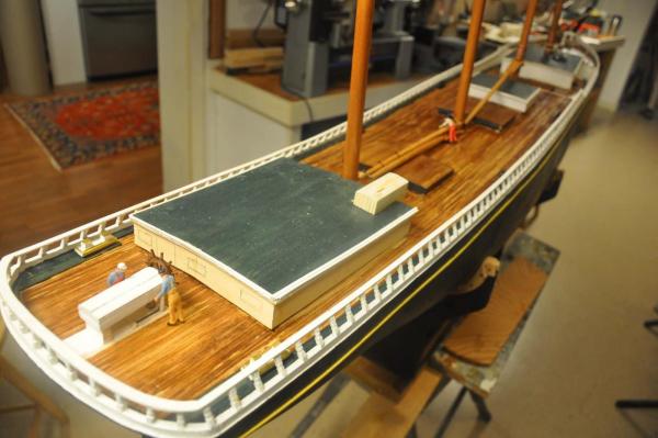
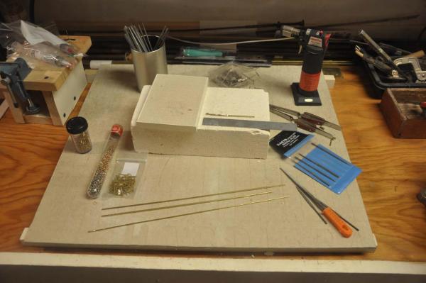
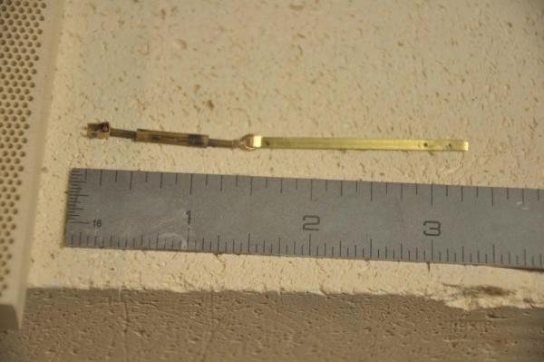
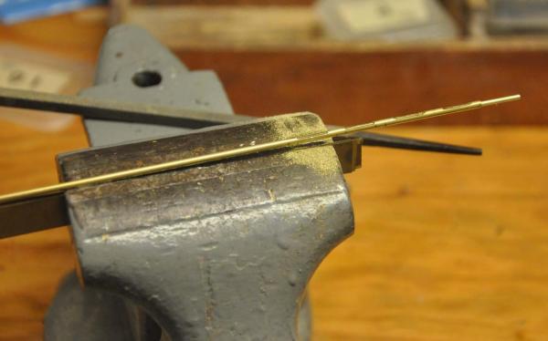
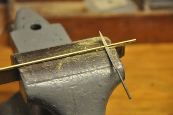
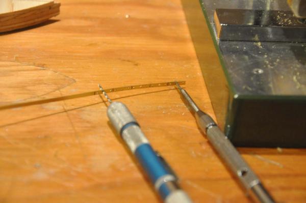
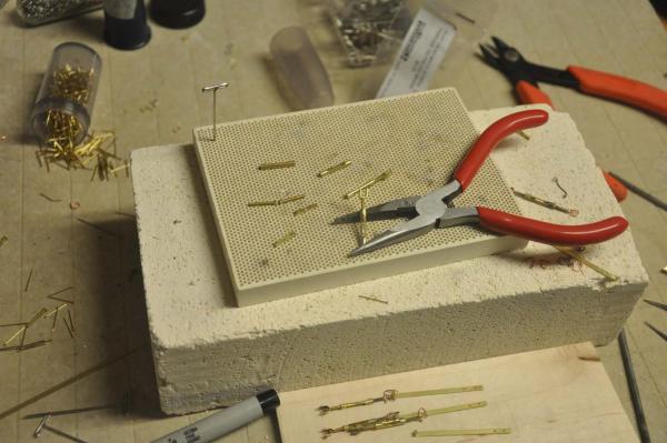
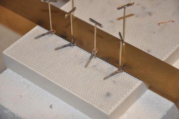
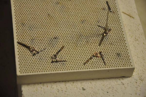
The posting below was done while I was under the microsoft Windiow Explorer 11 trance. After reading tech posts in this forum, I decided to try free fire fox and guess what.....it works. I went ahead and fixed the long posting of photos by putting them in the right order with a little text. much clearer As I said before........ well it was time to start production of perhaps 70 turnbuckles as well as to 'begin' completing and staining the deck; which means a few more bitts and things. turnbuckles. I set up the photos to track my trial and error approach. I am sure after this boat I will be better prepared to start the next. I also hope to get more comments. here we go set up: after watching several videos, you tube etc. I bought some tools and things and mixed it in with what I had. here I made one up; I used a jump ring instead of a shackle. here I put 1/16" rod in 3/32" tube for strength and filed away to make the side openings step 2 I used a tiny file to clean up the opening as we want to see threaded bolt inside step 3 I drilled three small holes through 3/32" x 1/64" brass. I then reamed out the middle hole by hand and then tapped it for 0 by 80 brass cap screw. It then threads on making a strong connection possible. I filed the head down on a 0 x 80 brass cap screw and tightened it up, and t hen bend it to make the clevis. small pin is to be soldered in ...not in photo. sliding the bolt into the barrel I crimped it. after crimping it still turns but will not pull out. I took a second cap screw and filed the head to a v groove and soldered in a jump ring. I am experimenting with copper brass and " mystery white metal" rings as eventually I need to make them look like galvanized. here I have a large failure rate as I am learning the skill. I made up shackles with 24 gauge copper wire and added the pins and soldered. I need help here I plan to dip all in blackener. The chain plate and schackle are to get black, but all above that is to become galvanized. Well we shall see how this goes; I have no plan yet other than possible silver paint for the galvanizing process. That will go for chain too when I get ready for the bow sprit. Deck completion: there is lot to do here, so I wanted to advance different areas so that I can keep up the variety of daily tasks. I experimented with stain color and opted for a little darker as I completed the foc'sle deck.I like the " motley look" the main deck is done, lots of detail let on the house. I started to trim out the hatch covers. The hatch frame is black and the tops shall be oiled plank. Lots to do to make the doors and windows and and etc reading the detail, I found that the aft bitts were totally sheathed in brass and like the bow have bronze caps. After installing I am wondering how to get the top brass to look more like bronze. I think I would like the look of a foil here and at the bow bitts too. not sure where to get brionze foil. I cut some tube to wrap the bitt tables. overall shot of the condition of the deck as we take another break to visit the kids in Arizona. I am now 'wicked' happy as I learned how to post pictures with annotations....good by to MS EXPLORER jon
-
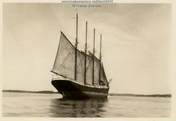
Patrick Spring is here in Maine. I am outside more and more. tomorrow off to see the kids......time does fly Sailing these schooners? From all I have read and been told, none of big schooners sailed well. The bigger ones, 5 and 6 master and another 100+ feet long could hardly come about at all and often would only jibe. Apparently to go from Maine to North Carolina they would often sail out to Bermuda, jibe 270 degrees and sail into the coal docks. Then coming north they could almost make it on one tack with Southwest winds summer and north east winds winter in real inches, the mainsail is about 2 feet tall. I have some 50 inch Marblehead pond yachts with 6 foot masts. they are made to sail! I will be happy to sail and turn at all. cheers here is photo of old 4 master leaving Boothbay harbor about 1930.
-
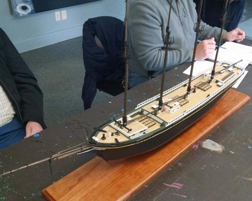
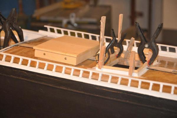
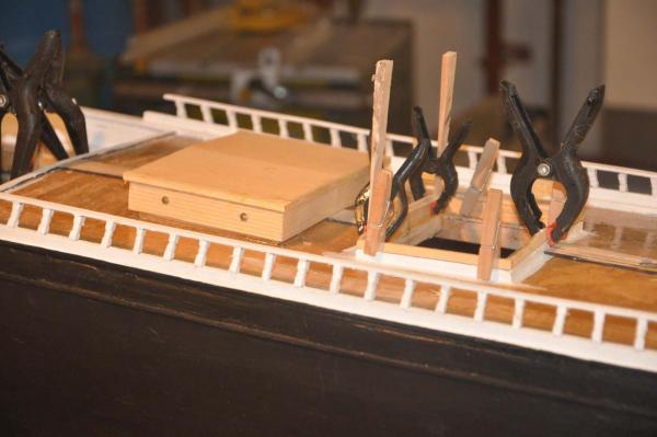
good news and oops We had our monthly meeting at the Downeast Shipmodelers Guild and Don a member brought in his Bluejacket kit of Charles Notman 1:96 . He is doing a beautiful job and it was enjoyed by all of us. We discussed different aspects of the coloring of oiled mast and decks, paint on waterways, roofs, hatches and shear planks. I came away feeling good about some decisions and relieved that I could use a yellowish tan as I had planned for the shear line and not figure out how to do gold....save gold for the navy If anyone out there is also building the Bluejacket kit give a shout. Every once in a while we need an oops to bring us back in line as students of this art. Jim, a long time expert on Maine schooners and a neighbor returned from a southern winter. He has several articles to his credit on these exact schooners. He came to the house to see my progress and we went off to the meeting. During the ride home he told me I had the wrong rake in my masts.........oops. I said [ the student] but I took them off the plans....he smiled and said perhaps I could check again. I found that when I calculated the rake I had set the masts at their correct position on the deck and pushed a brass pin one inch forward on the top riser [ mast step]. that was my oops..... when I rechecked the 1:96 plans it was still one inch at the cross trees to the vertical up from the step [ some how I used this measurement] I drew a new line down from the deck to the top riser and it was 1/4" forward to the step going to 1:48 that means my pins should be only 1/2" forward. For three of the masts this was no big deal. I had access to the step and with an extension on a hand drill could drop through the finished mast holes and drilled new pins 1/2 back to the right location. A little sanding on the blocking under the deck and all three went into line. The foremast was more difficult because of the completed deck house. I removed a center section of that roof and had to redo its hole as the main deck was the right position. I could not get a drill down through both house and deck, so I beefed up the blocking at the deck house roof and shimmed the mast to align. I shall also add a sharp pin in the bottom of the foremast when I step it permanently. In the photo I have turned the boat on its side to paint the yellow shear plank and you can see the rebuilt deck roof. Jim had recommended I add to my library a book called Fly Rails and Flying Jibs. It is published by Mystic seaport and contains an incredible annotated collection of photos of coastal schooners of the period. While looking through these added images it was plain to see that the small 4 degree rake Jim suggested is correct and the side view of the model schooner is much better now after the fix. so all is well and we are moving forward
-
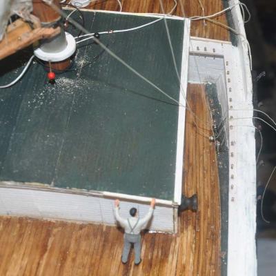
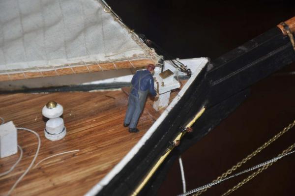
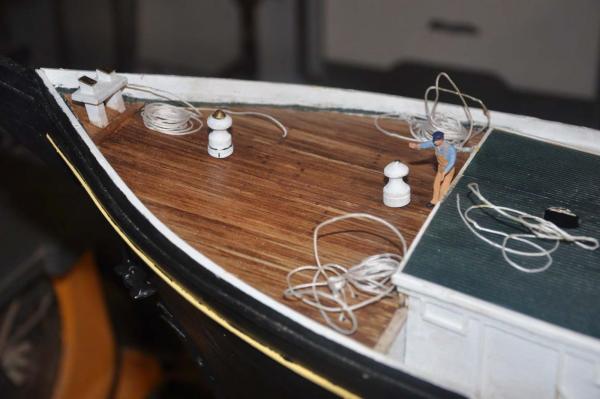
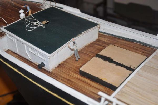
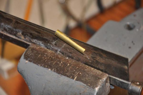
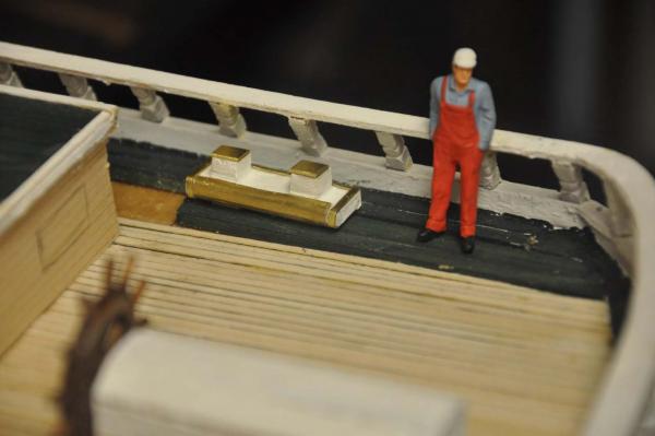
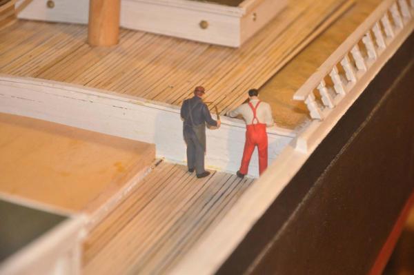
Patrick thank you for your encouragement and kind appraisal. I have so much to learn. turnbuckles under way....wow The scale people are great. I got them from the inet and they are Lionel train figures which happen to be 1:48. I wish I could find some mariners. These guys will work just fine. I will cut the hack saw and he can be pulling a line, the welder can visit a cleat etc. They are incredible to help me understand the size. example, I need to put in a few boards[ steps] on the side bulkhead for the crew to climb up to the foc'sle deck. Having that guy there in the photo helps decide that three boards 3/16" by 1/2" are just right. I am getting more excited as the weather turns in the right direction. so much work to do if I can get to the water this year, but also many coming distractions. I only have three days this week then off to see the kids cheers cheers
-
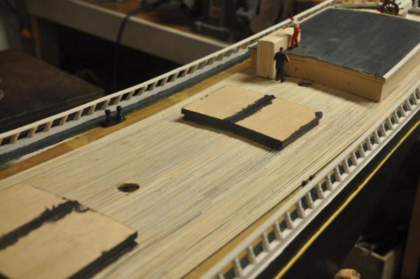
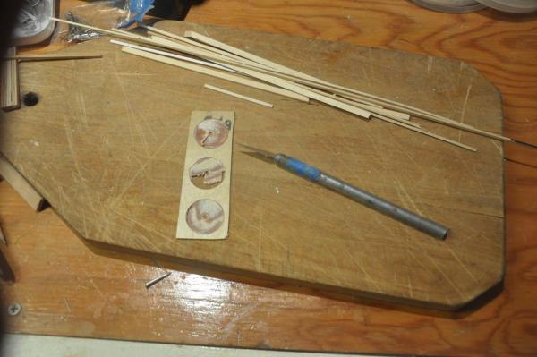
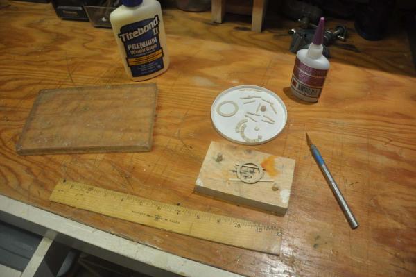
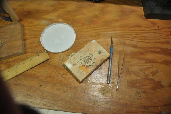
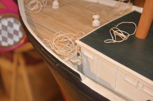
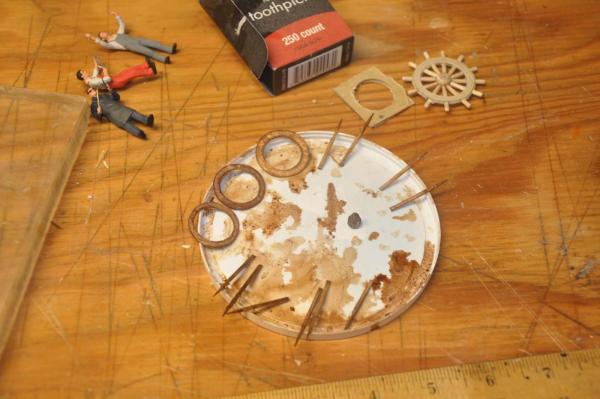
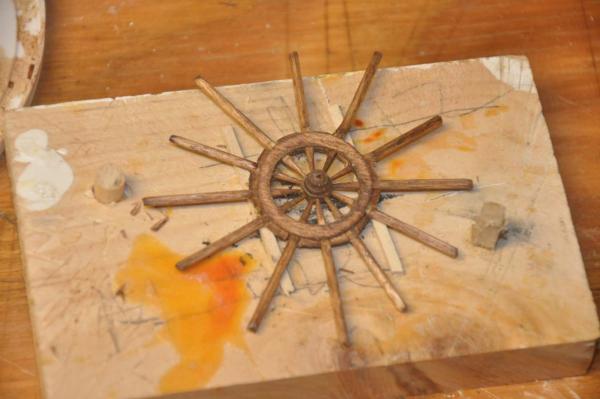
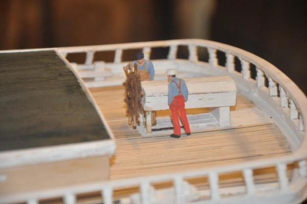
Well it's time for some more fun I started decking using 3/32" by 1/16" to replicate the 4"x4" decking on this older schooner. I typically use black permanent marker for one side to show the caulking. There is a little inconsistency in the intensity of the line with this approach, which I prefer. I will likely stain the deck later but need some time to think about it and see more images. Decking takes a long time, so I need to work on other things at the same time. Thus it takes longer to deck, but remains fun Time to build the wheel: I studied several approaches through other building logs and came up with the following concept. Cut three rims of thin plywood for the rims, turn a hub and use simple mortise between rims for the spokes proto type or practice...see photos I started by taking 1/32" birch plywood and cut three holes 1" diameter. I then used sander and files to get shape of on center large and two outer smaller. I then took 1/16 dowel and used small square file to cut mortise on either side. I added a pin to fit the hub and tapered them a bit. I took a 5/16" dowel and shaped the hub on a lathe and drilled 12 holes for spokes and center hole for shaft I did a glue up My crew of scale construction workers showed up, so I put them to work on the decking One of guys was a sailor and seemed upset about the mess of lines on the foc'sle deck After sizing the mock up and checking both the plan and several photos, I set my size to be based on a 3/4" ID for the rim. I repeated the process in a smaller size and stained the parts. I tried ends of toothpicks with their natural taper and liked the look. second glue up I set the wheel into the wheel house and with the figures think I got the size right. I am trying to put picture in the text and think I need to post then edit ...here goes it did not work so I try to attach them as a batch
-
Patrick Thanks I got lots of comments at the show where the interest is in the sailing. Oops I hope she works I am into the decking now and getting ready to start learning to solder so I can make fittings. I am also going to experiment with wooden hoops. The copper is a safe workable solution,but one of our guys at the show made them from real oak shavings. Got to try at least Cheers
-
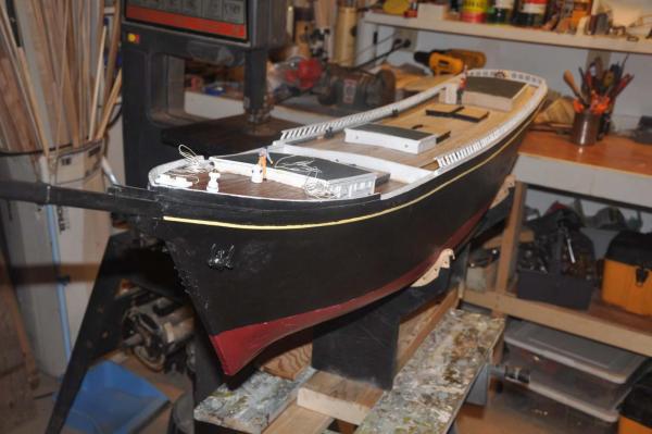
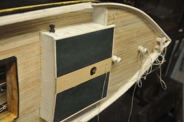
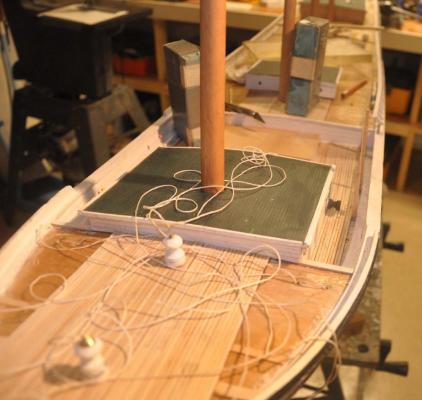
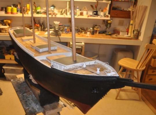
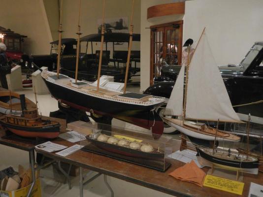
oops I hit reply too early The owls head Transportation Museum near Rockland, Maine has a models' show the last weekend of March each year. The various local clubs and other individuals and a few working craftsmen all come to share . The variety includes shipmodels, several more active RC clubs with Lobster and other working boats a big item. Military modeling both static and operating, cars , HO scale construction cranes and barges as well as furniture miniatures were there. The airplanes are amazing and the engineer society included all kinds of historical and adventurous made steam engines and moving tools etc. Our group the Downeast Ship modelers Guild out of the Maine Maritime Museum in Bath was well represented both at our own table and three other areas where members had their own show. FYI the Dark Harbor 17 sail boat in the photo chasing the schooner like a pilot fish is one of my older models. I felt I needed to have at least basic covers and houses ready before showing of the model. I made up the basic fore and removable middle cabins and committed to the dark green top color that was popular for an add. The books say a new boat was launched with oiled deck house tops, but after a few years they would be painted out. I am trying to show this model several years out, because the hay day of these ships was 20 years after this early one was launched. There were a few tables of miniature furnishings near us at the show, and a craftsman was there who specialized in the proxxon table saw. He makes amazing small scale picture frames and furniture. I shared my experience of difficulty working with the small wood and he was great. He showed me after market saw blades that he happened to sell and showed me how to fix my fence and few other hints. When I went home I installed the new blade, filed and reset my fence and I am confident I can lower my dimension limit from 1/8 to 1/16. That means I can rip down the decking. I will need more practice to get to 1/32, but isn't that the point? anyway a great mid point break.
-
just a short post as I raced to get ready for the annual modelers show at the owls Head Transportation Museum
-
The joy of living on the Maine coast is I have not too far to go. Actually I will not be able to get it in to my suv with masts and jib boon, as we are just @7 feet. A friend has a van and a dock. I also have a rough path through the woods to a pond behind the house. , but a long walk up and down hill. It will be a challenge. I plan to build a wagon like the pond yacht guys...but much to do beforehand Cheers
About us
Modelshipworld - Advancing Ship Modeling through Research
SSL Secured
Your security is important for us so this Website is SSL-Secured
NRG Mailing Address
Nautical Research Guild
237 South Lincoln Street
Westmont IL, 60559-1917
Model Ship World ® and the MSW logo are Registered Trademarks, and belong to the Nautical Research Guild (United States Patent and Trademark Office: No. 6,929,264 & No. 6,929,274, registered Dec. 20, 2022)
Helpful Links
About the NRG
If you enjoy building ship models that are historically accurate as well as beautiful, then The Nautical Research Guild (NRG) is just right for you.
The Guild is a non-profit educational organization whose mission is to “Advance Ship Modeling Through Research”. We provide support to our members in their efforts to raise the quality of their model ships.
The Nautical Research Guild has published our world-renowned quarterly magazine, The Nautical Research Journal, since 1955. The pages of the Journal are full of articles by accomplished ship modelers who show you how they create those exquisite details on their models, and by maritime historians who show you the correct details to build. The Journal is available in both print and digital editions. Go to the NRG web site (www.thenrg.org) to download a complimentary digital copy of the Journal. The NRG also publishes plan sets, books and compilations of back issues of the Journal and the former Ships in Scale and Model Ship Builder magazines.


