Jond
-
Posts
874 -
Joined
-
Last visited
Content Type
Profiles
Forums
Gallery
Events
Everything posted by Jond
-
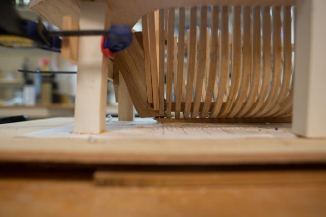
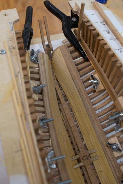
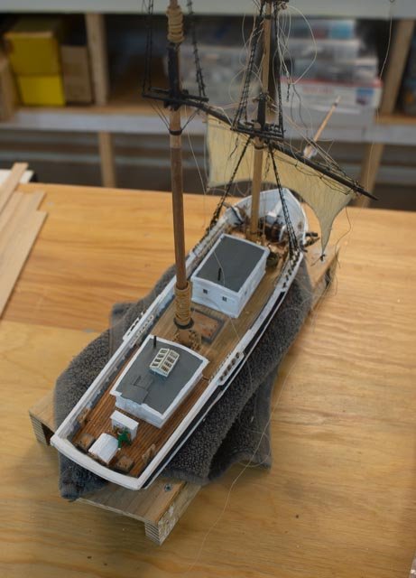
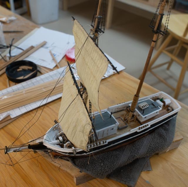
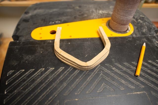
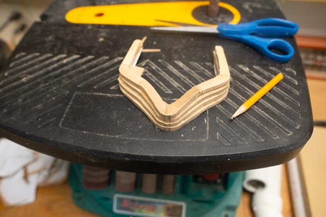
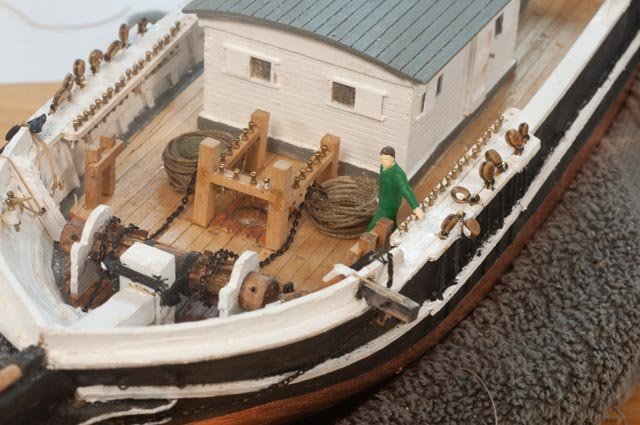
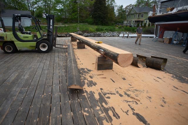
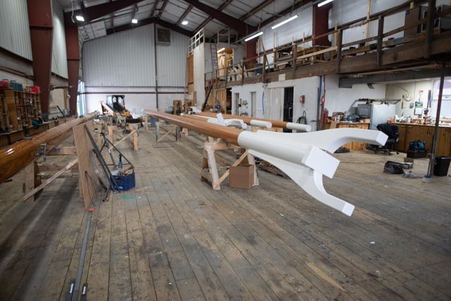
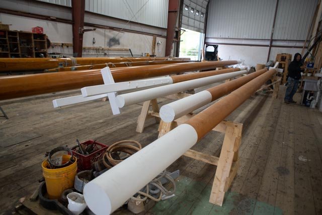
 Request for info on log pump I am building a model to represent a brigantine built in 1855 in Boothbay, Maine. I have read that these vessels were called half brigs here, but that is another story. We know the yard and the builder. We also know the builder was one of four Seavey brothers. Two of his brothers worked next door in two shops. One was a spar maker and the other built blocks and log pumps. Considering the location, the relationship etc., I have assumed the log pumps were utilized. I am doing an open frame under construction version of this half brig, H G Berry and I have decided to show something. Here is a photo of the model as it sits now. The two pumps are simple a bored-out dowels. I debated but did not add joints and bands. My curiosity is up though… to better understand what a log pump might have been. Let me first say open internet searches have not produced anything yet. I know that during this same period, 1850’s, as the great stands of trees were being consumed, that masts and spars were often made up. Therefore, the skill to do so would have been right there in the spar shop next door. To make four or even six 10-12-foot-long length carved out strips and then banned them together might have been easier that whatever it meant if one had to bore a hole say 10 feet down a log. Enough of my jabbering. I started this post to see if someone out there may be only one of two clicks away from one who knows something about these pumps. If you do, I would love to learn Thanks
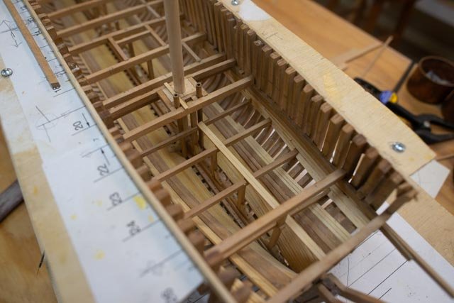
-
- 2
-

-
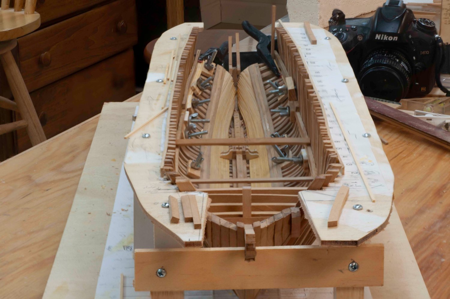
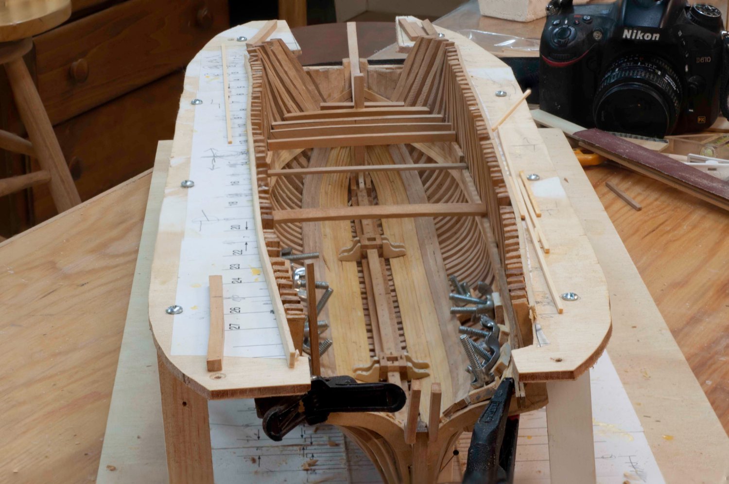
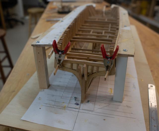
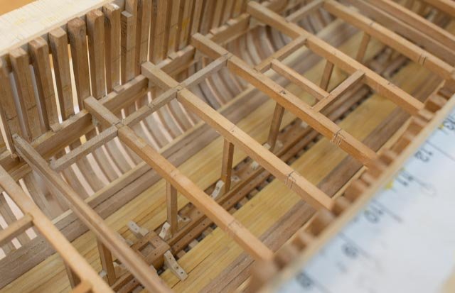
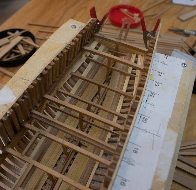
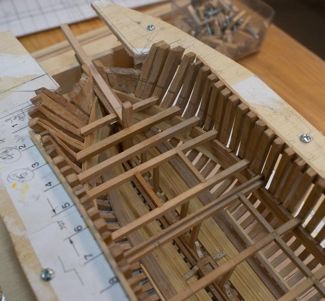
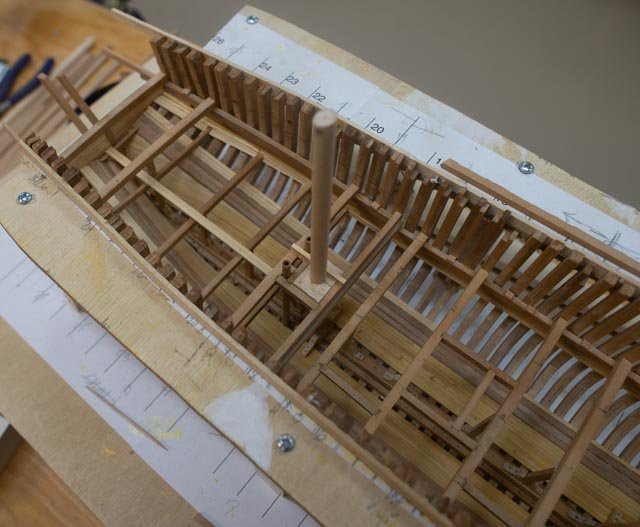
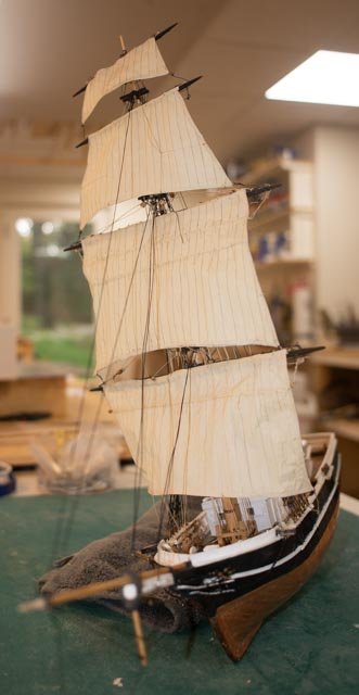
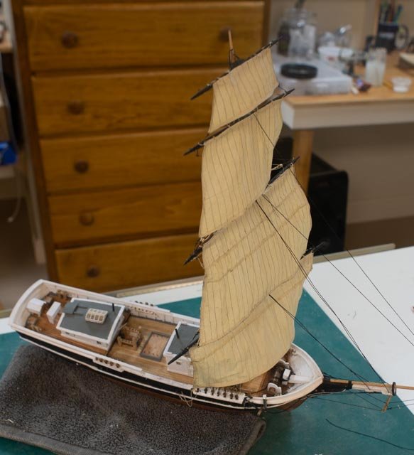
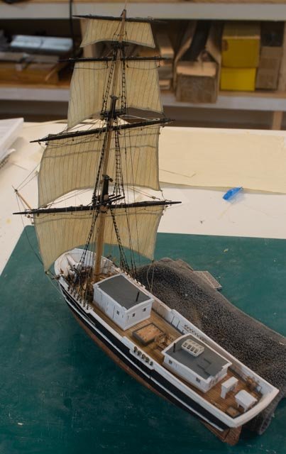
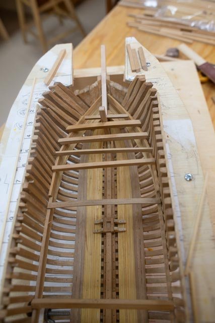
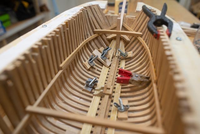
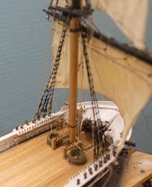
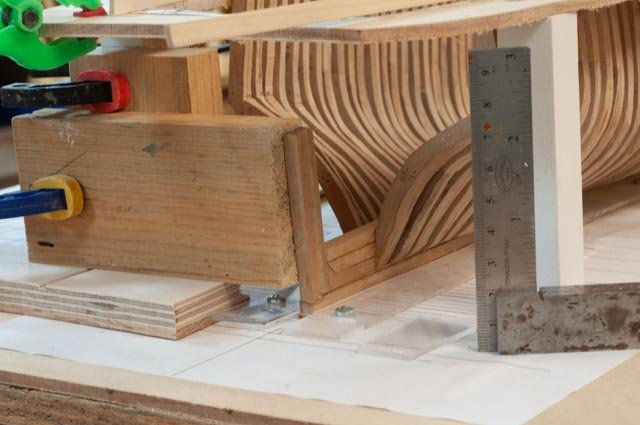
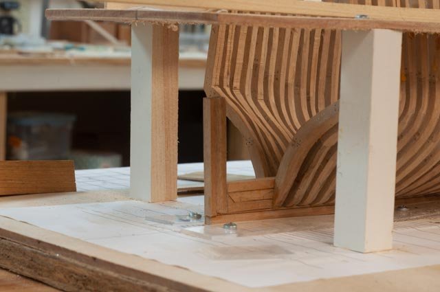
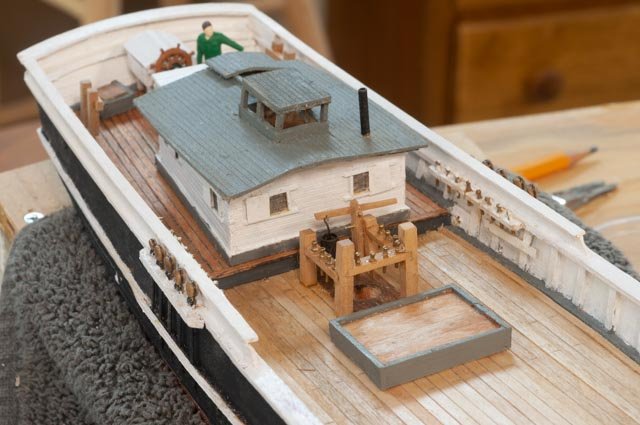
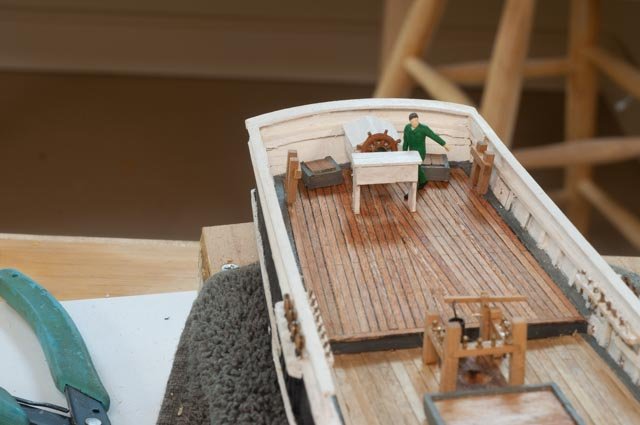
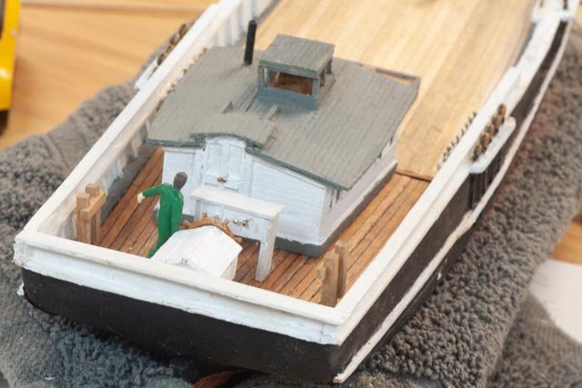
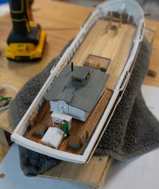
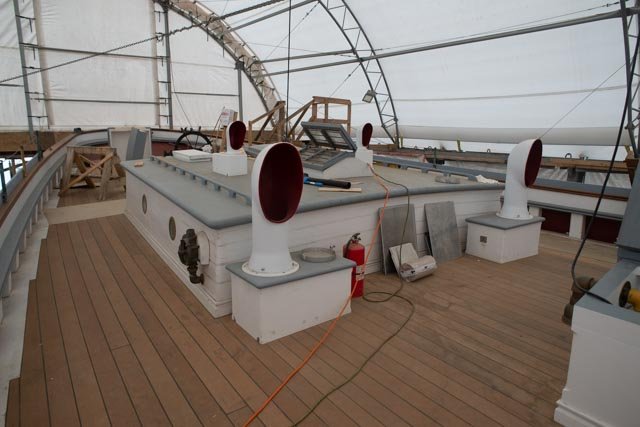
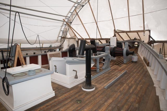
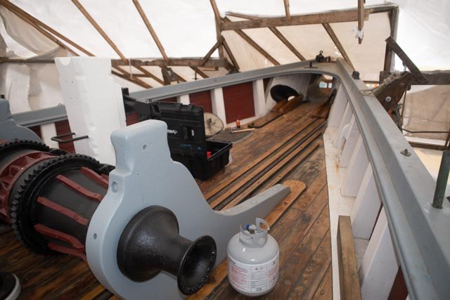
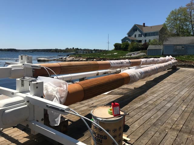
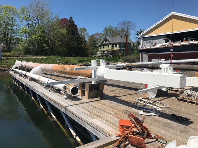
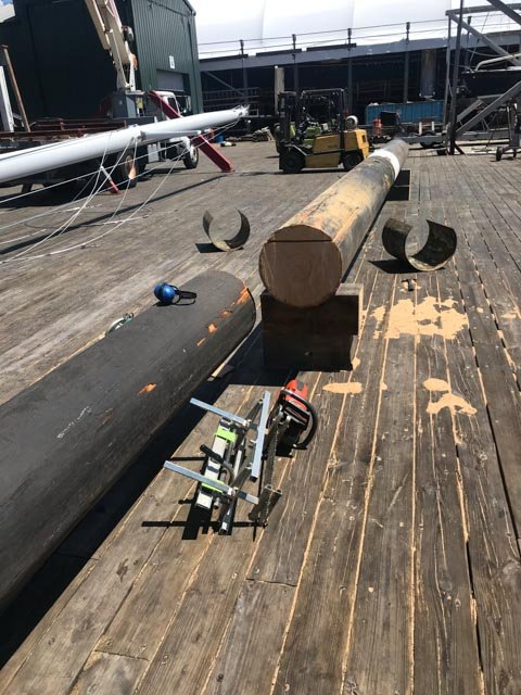
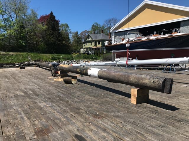
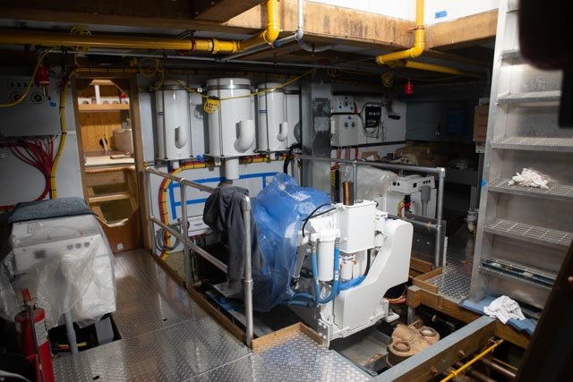
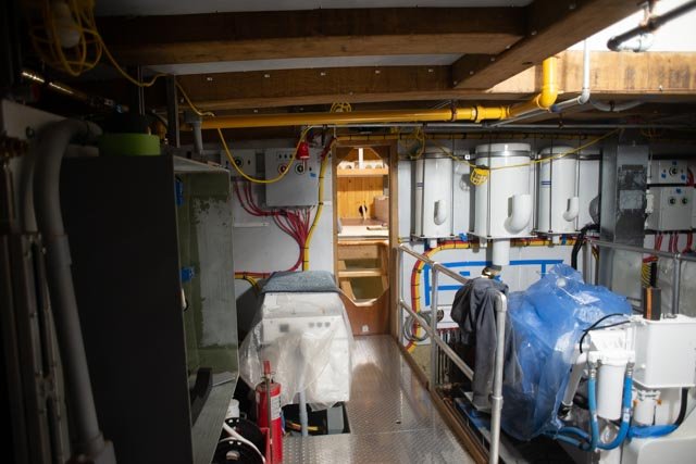
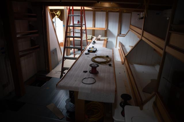
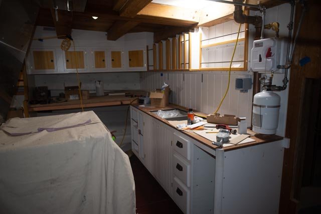
65 update on HG Berry. Brig under construction Last time I made an update, I was still adding ceiling and thinking about the next stage of framing. I continue to try to follow the Crothers book, but my work is a bit of free form. 1 here is an overview of the deck framing with beams resting on shelves, 3. in the aft section we have an unusual side to side main cabin. That means a clear interruption of the main level deck beams connecting at the shear line. I have dropped the large beams to the bottom of the cabin sole. More to come later 4 manufacturing knees. I am not sure how far I will go adding knees. One should try this though as it is truly amazing how many there would be if one added them all. The ¾ inch poplar stock gives me 5 at a time, so I do two giving me 10. Hopefully 8 make it through and into the model. 5 here I have added the bulkhead that separates the lazarette from the extreme aft section that houses the rudder chain. 6 here is the mid-section. you can see the first knees and connecting beams going in. 7. in this view it is easier to see the impact of the main cabin to the framing. There are two main beams that are not connecting the share line, interrupting the affective horizontal truss. In normal design the side walkway framing around the dropped cabin is an affective small truss compensating for the loss. The wide cabin makes this alternate not possible, and a clear weakness for stormy weather. As an old engineer, this layout bothers me….. but they built it! 8 here is a detail of the bow section ; we see stanchions on the keelson rider with fore and aft knees going in. I was thinking of a lower bulkhead to separate the chain locker like in the schooners I have seen, but it would be a bit of a guess at this point, so I won’t. 9 here I have built up the main mast deck frame. I cheated though. I learned in the two schooner rebuilds I watched here in Boothbay that they use nested 6x6 members through which they cut the hole. I used a little plywood since it is buried under decking. 10 here I have set a few planks on the cabin sole. They carry aft to include the lazarette. That will be accessed from the cabin. In these last two photos one may notice the bored out hard wood dowel to represent two log pumps. In the history of the shipyards that I did this summer I learned that the brother of our builder had a shop next door where he built these pumps. He also with another brother-built blocks. So surely, the pumps were included. I could not find however any technical information of the concept of a log pump and hope to find some. Example: were they built up of strips and caulked and banded or really just a hollow log?.......I hope to learn more Cheers

-
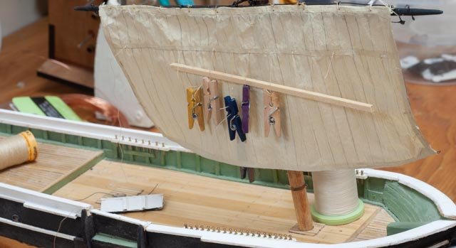
Wefalck you probably noticed in photos the main mast coming on and off the vessel as i progress. I will take a few photos of adding sails. I learned before to sew the sail to the hoops , and lash it to the boom and gaff while it is laying on the desk. I then tie on the various lines and lift the whole thing into place. so far it works well. I am probably two weeks away from that step. I will have the stay sails to go on right after that , and they will be done in place. topsail schooners are the best of all worlds I believe for sailing these waters. I have a few projects in the way but will also build on one of these days cheers
-
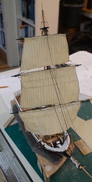
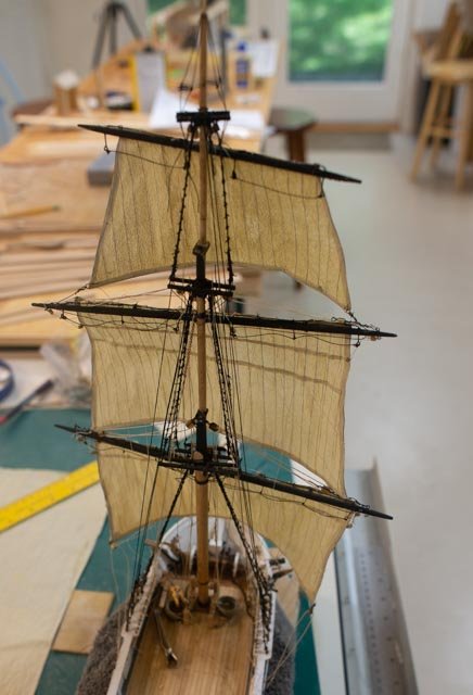
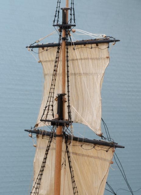
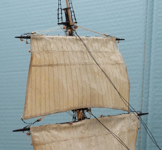
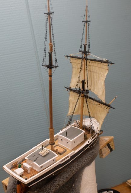
64 update on Albert…the sailing brig Just a few shots to show that I am working away on the side to get this model done Since last time I have added the 3rd and forth sail to the foremast and brought all the lines down. 1 here we have the topgallant set 2 here it’s hard to see but the lines are coming down and getting tied off 3 and here we have the royal set and some of the bow sprit rigged 4 here I can see I need to work more on the sail shape. 5 in this view we see the work on deck is coming to an end. I need the boat rack and boats for the fore cabin. Off camera I have started making the remaining 7 sails, and the first ten coils. Update on H G Berry tomorrow
-
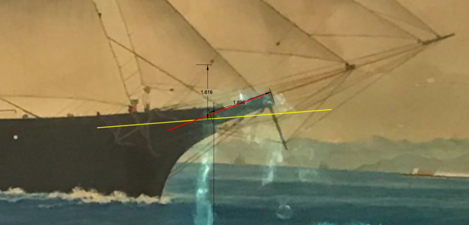
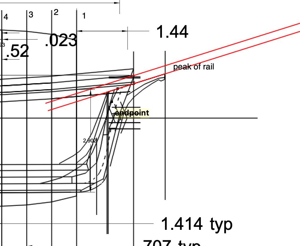
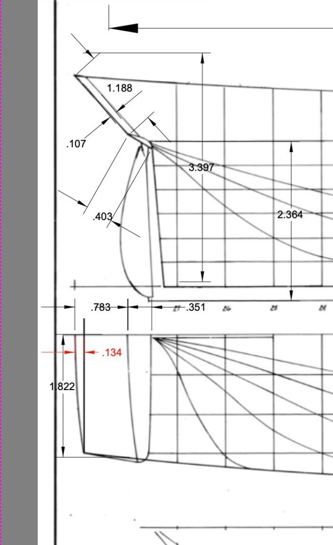
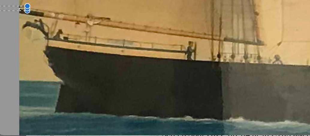
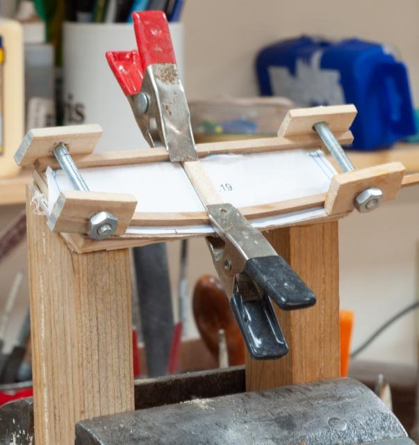
63 set up for transom and Bowsprit Since my plans are limited and unspecific toward framing, I need to look ahead a bit and determine how to make up the two ends of this vessel. First up ....where am I as I do this step. Here are two shots using the merge/ blend layers so we can try at least to have the whole length of the vessel in focus. 1. looking aft I have installed the lower ceiling and bilge keelson / stringers. I say that as in this smaller vessel they are together or combined. In Crother’s book he shows this and on larger vessel cross sections they are separate. I have added the shelves under the deck clamps and a few ceiling members there as well. I have a few more to go in the aft section I may get ambitious and hang a few beam knees, and they fall inside the ceiling as I understand it. 2. looking forward the different woods show up. Poplar is the current knees over cedar ceiling and Costello frameworks now to the task 3. here on the only line drawing I have; I projected the bowsprit angle as it comes on board. It clearly penetrates the deck as it come inside the stem. It then hits the Samson post below deck. 4. in the painting of the Torrent, we confirm this arrangement and angle. I also took my dimension for the projection. 5. Here on the line drawing of a similar Bath Built brig I have been using, I have studied the angle, and size of the transom. 6. here on the painting of the Torrent, we see two things of interest in the transom. One is a reminder that on this vessel. and the H G Berry that was recorded to be similar, the cabin comes side to side. There is no deck level passage aft to the wheel. The H G Berry , our model, will not carry the cabin aft with chains to the forward wheel. Regardless, there is still a difference in the stern shape that I will need to figure out 7. Here on a temporary jig, I am experimenting by compound bending the outer frame pieces. We’ll see if it works. 8. Looking down at the bow I have used maple for the Samson post and bow sprit. I have started to rough out the deck beams. I will focus on the fore deck first. I am not sure how much decking I may install. Perhaps the center 1/3. We’ll see 9. Looking down on the stern area I have more to do before adding the transom. I will build a bulkhead at the after end of the ceiling to separate the " Lazarette that contains the chain and " tiller" from the wheel. I am debating the access route. more later I will also figure out the lower deck for the main cabin. A lot to think about. I do not expect to get it right the first go…..smile • Cheers


-
Allan Thank you for following up on this idea that the adventure is ongoing and the model is only a part of it. As a side note I followed a lead one day and went onto Thrift Book .com. when one types in a search topic, one gets lists of older books as opposed to Amazon or B&N that focus on recent publications. I found a 1948 publication....The Maritime History of Maine. by Rowe. It was an excellent read and I learned much more of the overall downeast region and the different ages of sail. Lots of fun cheers
-
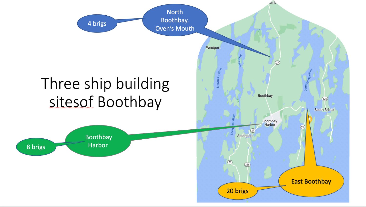
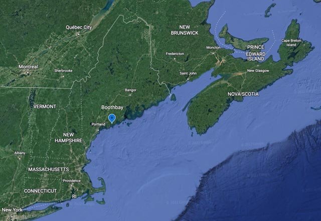
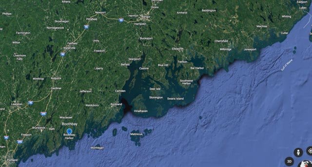
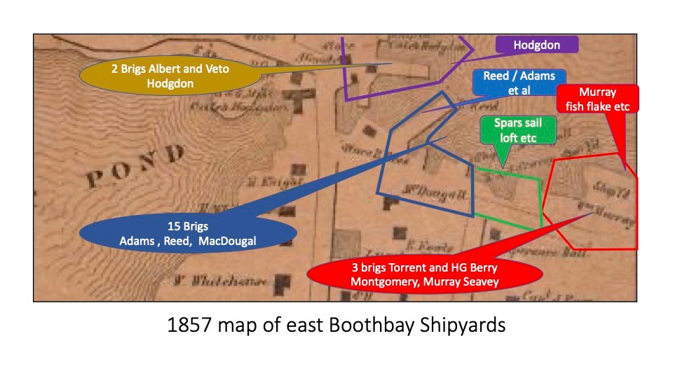
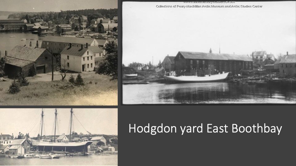
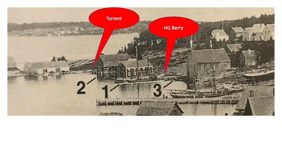
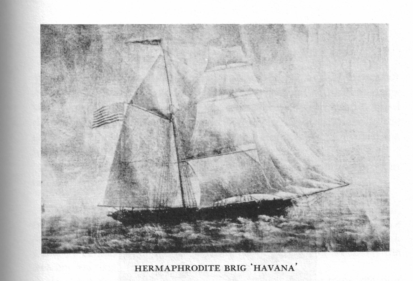
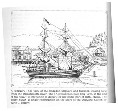
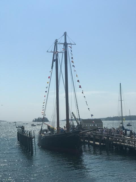
62 history of yards that built the brigs of Boothbay In my first posting I said I would tell more about the yards that built the 32 brigs of Boothbay. My reason to delay was that at that time I was still doing my research to give a talk about the first century of ship building here in Boothbay. I have pulled together some points, more a summary of the findings relating to Brigs, which is related to this build. The earliest vessels built in Boothbay were small to medium schooners as early as 1760. A few were in the revolutionary fleet that was sent to take Castine in 1779. They did not do well but that is another story. 1) For those from away here we see where Boothbay is located within New England. 2) Here is most of the Maine coastline. The major center of ship building was up and down the Kennebec River including Bath just to our West. Bath Iron Works is still an active navy builder today. 3) Here on our peninsula, between the Sheepscot and Damariscotta Rivers, we had three areas of Shipbuilding. East Boothbay was the main center; the others were active in early years. a) North Boothbay was active 1810 to 1852. They built there originally for protection from the British, but when vessels got bigger, they moved to join East Boothbay works. They built 4 brigs and a bark there. b) Boothbay Harbor was active from 1840 to 1920. It was mainly the big boom that lasted ten years before 1857 when 6 to 8* brigs were built downtown. Then in the WWI boom years, 10 big four masted schooners were built. Today there is an active 700 ton marine railway and large vessel repair center that recently rebuilt Ernestina Morrissey . * there are a few brigs that lack building sites, but it's suggested some were built downtown. 4) This map shows the yards of East Boothbay between 1825 and the crash of 1857. I refer to the colors in the following text. a) Purple on top: Hodgdon started in 1816 before moving to East Boothbay in 1825. They are still running strong with Tim Hodgdon of the fifth Generation is charge. They built two brigs in the early years but returned to their bread and butter of schooners through the remainder of this period. the yard today is a marina and Hodgdon are in different facilities. b) Blue on the left: The Benjamin Reed , Adams et al yard built most of our brigs as well as a few ships. They ran until 1920. The yard is still active today c) Green in center: this area included sail loft, spar yard, block, pumps, coal, paint etc. Up to eight different businesses over the years. The Seavey family also built a few vessels there and next door on the Murray land. It is our build's H G Berry that they built . The multiple lot yard was reconsolidated after 1920 and eventually sold to the town. It is the Shipbuilder’s Park today. d) Red on the right: this property started as the Murray lot. Several vessels were built there including our sister Brig the Torrent , each by a different builder. The yard grew extensively in the 20th century and is very active today. Let’s add a little more description to the early East Boothbay yards that built most of the brigs purple Hodgdon yard 2 brigs The first two brigs were credited to be built by Caleb Hodgdon in 1825 and 1830. That yard, never built another square-rigged vessel. They were very successful building primarily schooners through century. The two brigs, Albert and Veto were very similar. They were 71 feet and 120 tons. Albert was built first and little information on her exists. 5. Veto in front of Hodgdon Mills 1830….built in 1830, she was first a full brig. We know she was sold to a merchant in Bath in 1831 where she was registered. It was recorded that in the early years, 1825 onward, that William and Andrew Adams leased space at Caleb’s yard. They worked there and in other yards for the next 25 years. Perhaps, since their future included several brigs and even ships, they were the actual builders of Veto. Often the owner of the yard took credit for the build. 6. This compilation shows three vessels being launched at Hodgdon. Our first two early brigs were built here but since then many great schooners. Note the Bowdoin in 1921 and one of their three masted schooners around 1890 Blue Benjamin Reed/ Adams/ McDougal yard Between 15 and 20 of the 32 brigs may have been built here. William and Andrew Adams worked mostly here but also built in other yards. Also, their relative John McDougall joined them from north Boothbay in 1852. Together they are credited with 12 of them. As stated above, Benjamin Reed the landowner is also credited with a few. It is not clear how he participated in the actual build. Several other brigs either have no builder listed or one-time builders. Again, investors were often listed as participants in the build. Green. Seavey yard amongst multiple users. This yard included up to eight different businesses. During the period of the Seavey family a few vessels were also built here. 7) This view is from behind the Hodgdon yard looking east into the Damariscotta River, we can see in the 1893 photo where our two big Brigs were built. H G Berry was built by Seavey, so this could have been either the yard to the right of the sail loft that they owned [ red sign] or near the Murray property where Torrent [red sign] is shown. The two vessels were very similar and only one year apart. My point is either way, one build 1854 and the second 1855, and both the same size, there had to have been much similarity. Red …. Murray. Charles Murry was the rightful builder here and he built one known brig and a few barks before the 1857 crash. It is believed that the other builders-built Torrent here, as well. Unfortunately, the captain and one of the investors are listed as builders. It is the connection of the family land owner Montgomery and Murray intermarriages that suggests this site. 8. here is a view of Havana. She was a mid sized half brig at just 100 feet and 221 tons. she was built downtown Boothbay Harbor 1853 by Charles Sargent one of our more famous builders. He was attracted away to the Portland at the end of the crash in the early 1860's. Not part of this build but he built our best ship too. now back to work

-
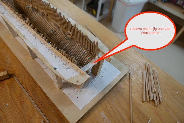
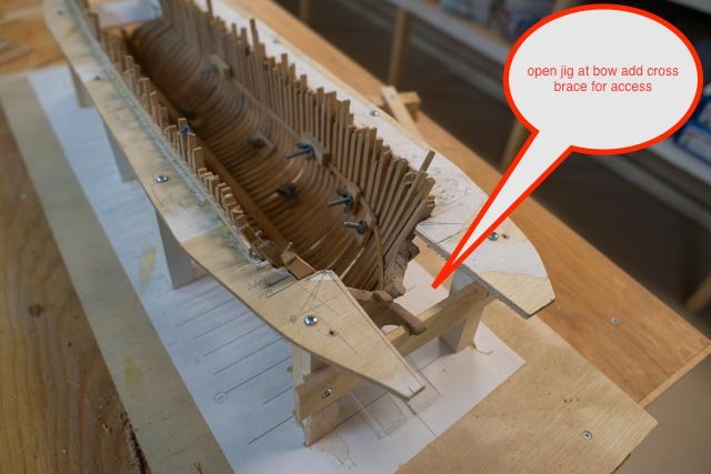
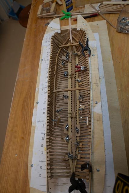
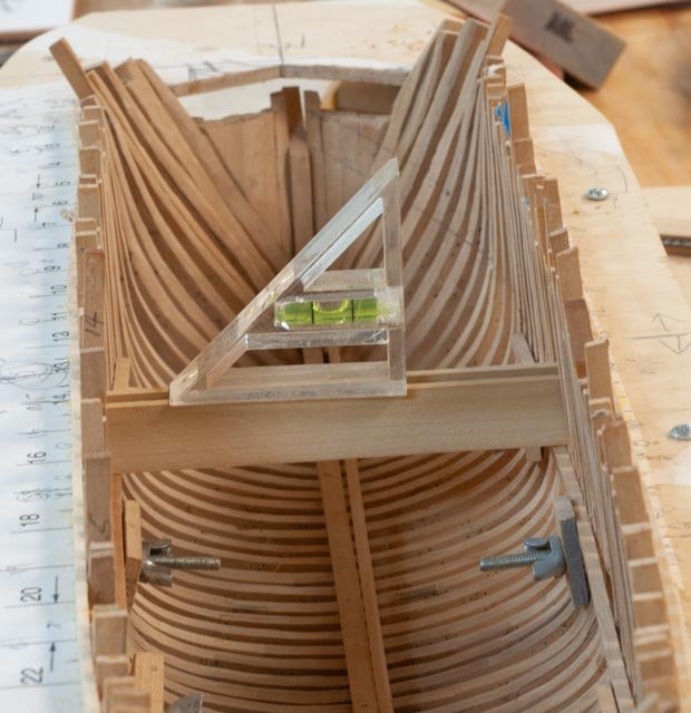
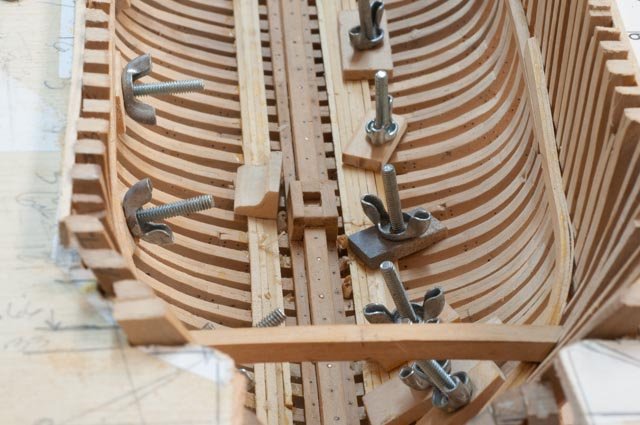
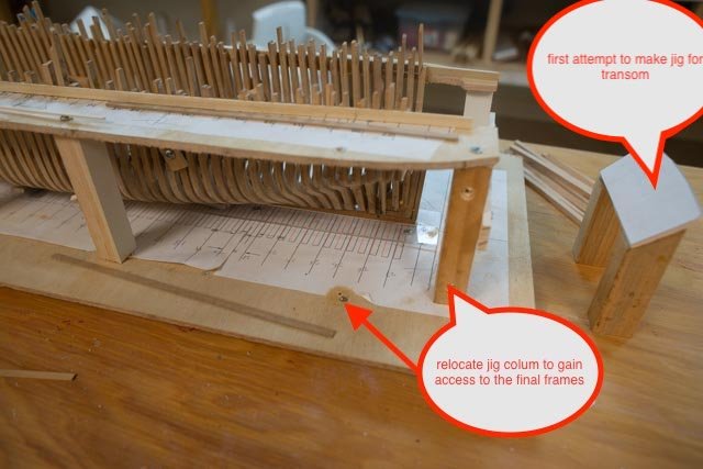
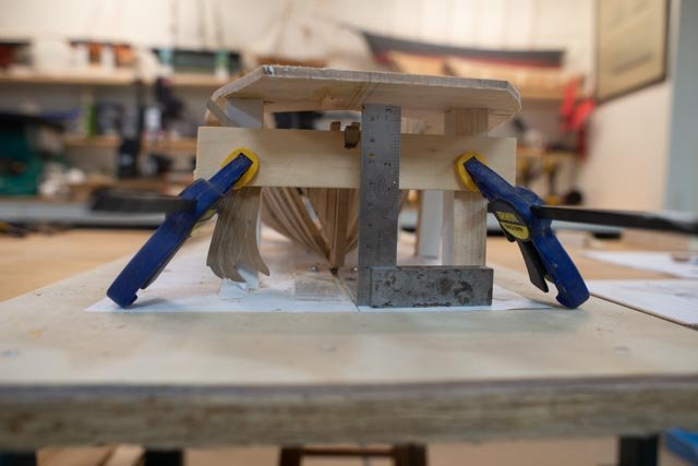
61 update on the larger half brig HG Berry Since getting the new light I am so much happier looking inside the hull. The frame are done. The transom is not. I will get there. First I want to stabilize the hull with all the other internal work. First up are changes to the jig that was needed to help me progress. 1. As I was completing the frames, I needed to move around some of the jig columns. They are screwed top and bottom so moving them was not hard. I also need to figure out a jig to facilitate building the transom. As I have no drawings I am studying the Crothers details to figure out what to try. 2. Here I needed to remove the end of the jig and add a cross brace for now 3. Here at the bow the same story. I need access to build out the bow. 4. In this photo, the last with bad lighting, we see the clamps are in and the ceiling started Now let there be light 5. Here I am checking the deck clamps for level 6. Here is a shot of the blank I an making for mast step knees. I made two to get ten knees. I am using poplar 7. In this progress photo we see the long process of building out ceiling and other internal work. I just can’t say enough about the benefit of finally having for less than $100 great light. now for some more history
-
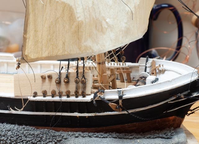
60. update on the rigging of the small half Brig Albert It is time for masts to go on and be set. I believe the best approach will be to do most of the foremast work before setting the main mast. Having the half brig and half schooner rig makes that a bit easier. 1. here we are setting the dead eyes for the fore mast shrouds. I am not sure how much the fore course sail being in place will affect me with ratlines. 2. The shrouds and ratlines went OK. Now to look at what we have on deck. The fore cabin, “Caboose” as I learned, has been resized and I think it works. please note in this photo all is a bit dark 3. Here I have hung most of the lines on the fore topsail, so as I attach it, much of the delicate work can be done. We’ll see how it goes. I have the main mast and cabins here for the photo but will remove them until I complete the foremast work. ditto on notice the darkness in the photo A few days later we have the fore topsail all in place. I got tired of not having good light on the center project table and bought a new 4-foot LED strip that affords one to change both intensity and color. I love it…I can see inside the hull!!!! 4. Here we are looking in normal indoor lighting. 3500 K . Some people like this more traditional look, however. 5. Here is the same view with the switch to daylight. 5000K. I love it. The blue is just a big cut up cardboard box with blue latex. A few details 6. I am following the Crothers guide as to what line goes to what pin. I try to mix up the thread colors a bit as well. It is going to be tough to get all those little coils in place…we’ll see 7. Here if one looks closely all those lines are in place, leech line, clew line, reef tackle, sheet, lift etc. Note there are lines on the first 7 pins on the P & S sides and 4 at the mast rails.I am not very good at judging the size of the thread to use. I do not like however over heavy lines. I beefed up the lifts, topsail yard halyard and sheets. The rest are all thin. 8. Here all the topsail lines are on and fed down to pins. I used black line for the sheet chains die to the small scale. I kept chain for the top gallant halyard. 9. The bunt lines are there, but the thin thread does not show up well. I will use darker thread on the top gallant I remember this process is a learning effort for me, so if each build gets better I am happy. next up a little history on the yards and start of the insides of the larger half brig
-
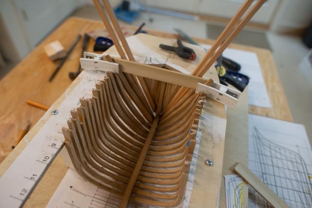
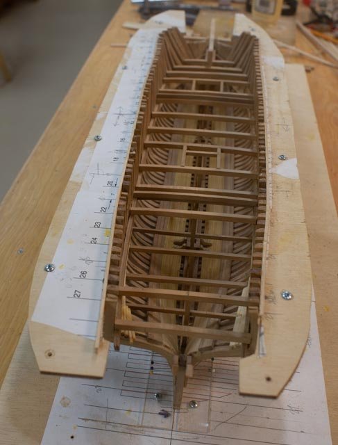
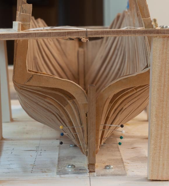
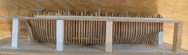
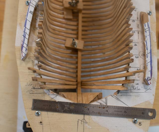
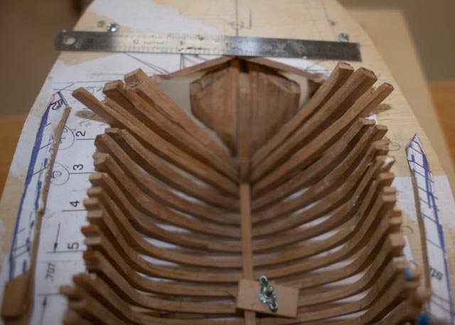
59. complete setting the frames at the stern of the larger brig I believe the real celebration is the whiskey plank. I cheated and had an extra dram to celebrate the last frame. Still lots to do but here we go. 1 moving aft I had to remake a few frames and get them meaty enough for the bevels. Here I lined them up to start a little preassembly sanding 2 here came another. This was also the step to verify where the full frames would stop, the space above the keel be filled and the frame was going to become the first half frame. 3 in this view I have done all the full frames. I also started the inside fairing up forward. 5 now it’s time to set up the stern post. I had to make a new one. 6 in this view the keelson and its rider are connected into the sternpost. There is also a new filler to receive the last three half frames 7 the first half frame is installed 8 here all there half frames are installed pinned and glued. Notice how big they are at this point. lots to sand 9 Ta da. All frames in place…yippee 10 it looks like a good bit of sanding once we get the insides set up and can get rid of the jig base. All for now
-
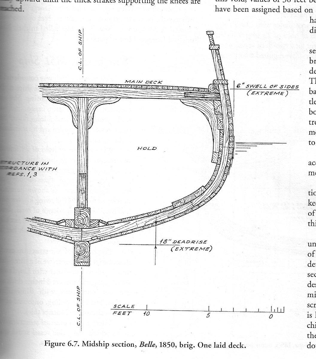
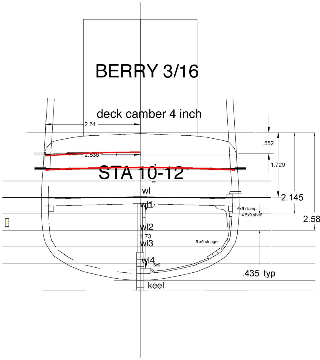
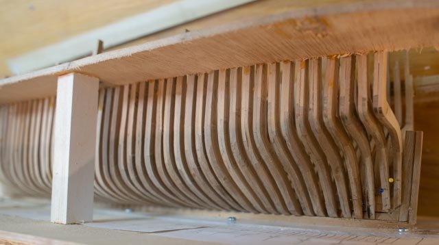
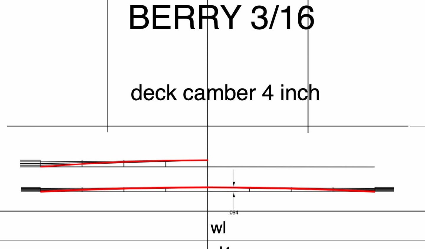
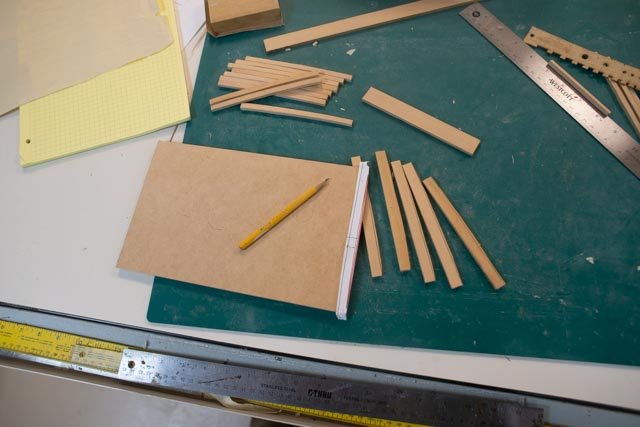
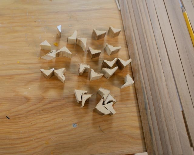
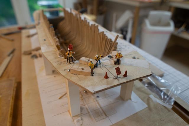
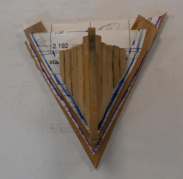
58 time to figure out the deck framing for the large half brig H G Berry The plans I was able to obtain for a similar sized brig did not include much detail. I am basically using the Crother’s book and former experience of the Maine built schooners of similar size. This hull in not that much bigger than a schooner of similar length. That gives me a sense of size of frame deck beams etc. I thought that I need to reference something more specific before cutting up the remainder of my precious supply of Costello wood. 1 this cross section comes from the Crother’s book. It is a cross section of a merchant Brig that I will follow. 2 here I have taken the center frame layer and annotated it. I can then measure and get a sense of the right sizes for the knees, clamps, posts , bilge keelson members etc. The book includes a table with the beam sizes offered and they make sense to me. Since they are doing more than simply holding up the deck they are listed as 12-inch deck beam spanning just under 9 feet. I will do every other one with a smaller one without knees alternating. The knees on the center post and beam end reduce the effective span from almost ten to perhaps 7 .5 - 8 feet on average . This actual span suggests 12-inch beam to be quite heavy. 3. From this drawing source and a comment in the text of a different chapter that a 40-foot merchant vessel would have a 6-8 inch camber I have decided that 4 inches would be best. In the red curve we see how little that camber is. 4. here I am using a the “camber”curve and sanding the tops and both cutting and sanding the bottoms of the beams. I then passed the beams upside down through the thickness sn=ander to try to get them as close to right as I could. 5. here I have cut out a lot of potential knees. I did this in a piece of 3/4"poplar, so it's not too bad if I need to throw them away and start again. I also thought a different wood might be better anyway. I understand the deck horizontal knees were often pine. These Boothbay Shipyards rough cut most of their timber on the other side of the same Damariscotta river and milled the lumber at the local Mill. This oak at this time was still plentiful and pine and fit supply overwhelming. 6. before we begin the next step, I wanted to celebrate that the crew just showed up. They are diecast toy road workers whose roll will be adjusted to shipwrights. for a welcome aboard, let them dig


-
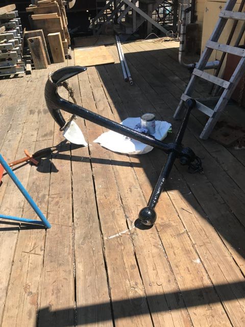
Wefalck thanks for your comment. I totally agree. Much of the difference between a 75 foot and 110 foot long brig is in the bow area. I show the anchor line as part of the explanation of how tight things could be. As I am tying off the multiple lines for the square sails above, just image; working the jib sails and taking in a square sail at the same time. They would have been on top of each other. regards
-
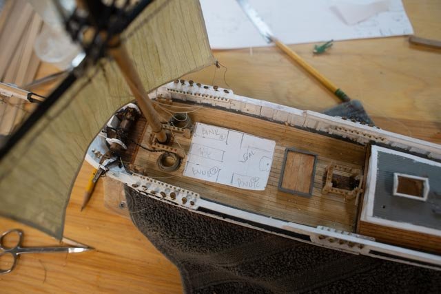
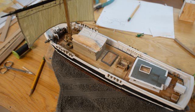
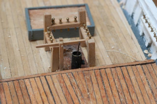
57 layout of the forward deck and set the mast on the small half brig Albert I thought it important to get the ‘furniture’ and big items done on the fore deck so I might set the fore mast. I have gone as far as I dare with the main course sail without being able to tie off each line as it is added. I also need one final look to resize the fore cabin. 1. Here we see the anchor gear with the port side anchor stored aboard. I thought there just is not enough room to lay it down as on a ship. 2. Here we see the other side and tightness of the area. Using Crowther’s pin lay out, I saw the need for all the pins on the extended foremast fife rail. More on that later. 3. Here I added the 12-foot-wide cabin. As it needs to crowd the back side of the fife rail, we also see the narrow access around its sides. It just does not work for me. 4. Here from the other side ditto 5. After setting the foremast, I removed the cabin and redid a small floor plan reduced to 10 feet wide. We get 6 bunks and tight common table. Much like a sailing yacht of today. the galley stove needs to be centered so the boats can ride either side on the roof. 6. I made up a cabin block that will be clad and have placed a quickly whittled boat to simulate the massing. I plan for two boats to ride on the cabin. 7 here is the completed log pump. I shoe it because the little side spout is the only soldered brass tube on this build.....I think Now that I have set the fore mast in place, I need to plan how best to sequence the rigging. If I add all those leech lines, clew lines and bunt lines every pin will get used. I think it better to start with the inside most lines and work my way out. That would make the lower mast shrouds come after some of the running rigging. We’ll see how it goes. I also worry of the push and pull to the sails, so they don’t end up all wrinkled. That is why I feel it better to add the upper sails in place. All for now
-
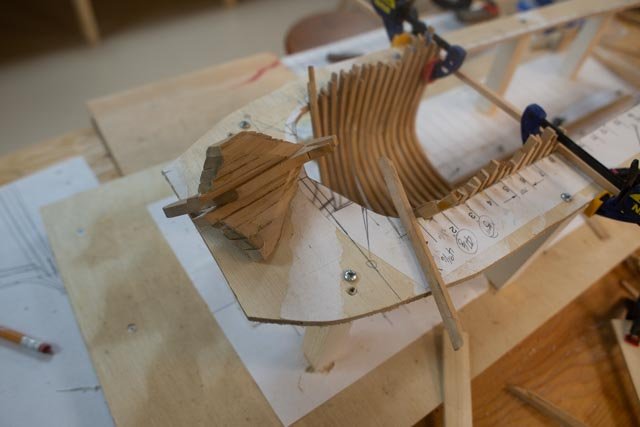
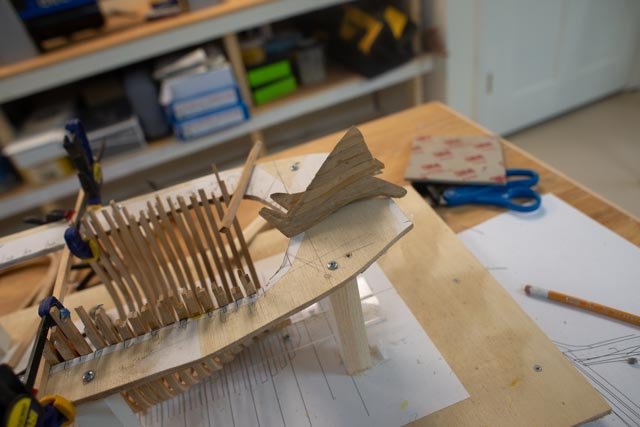
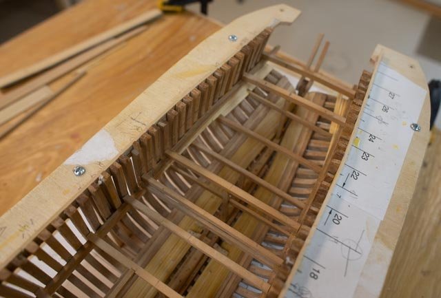
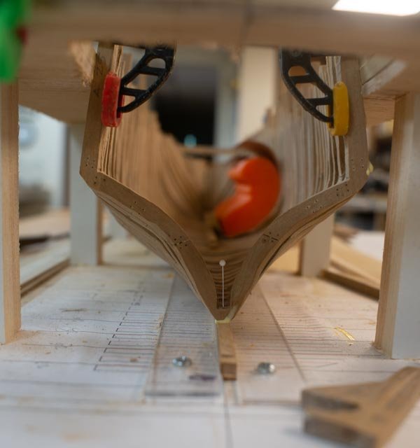
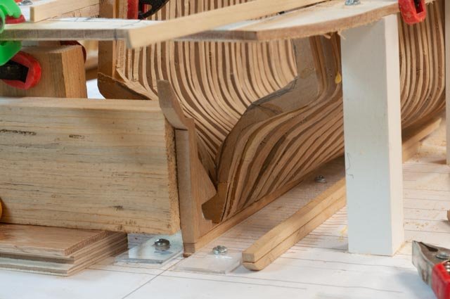
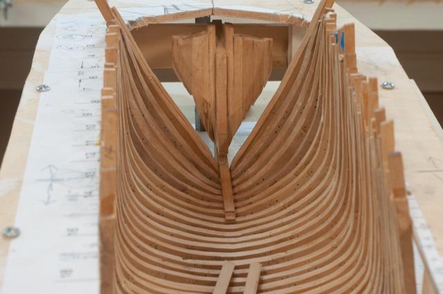
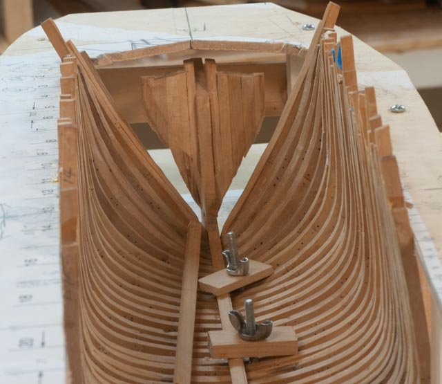
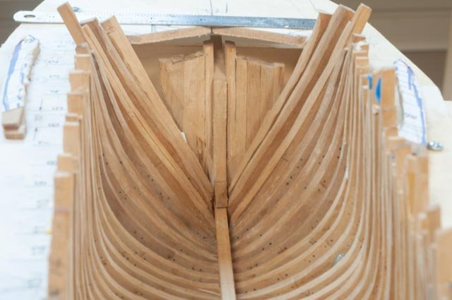
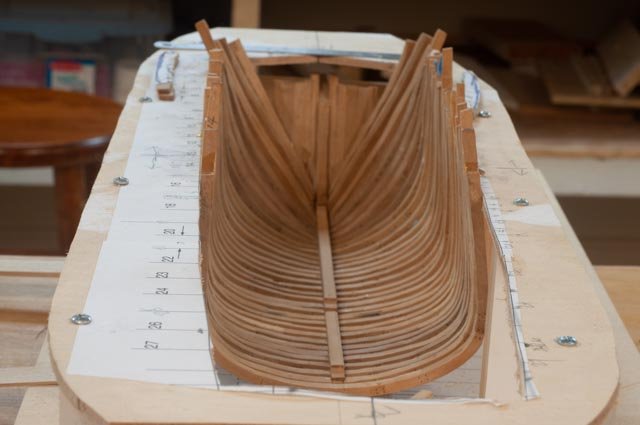
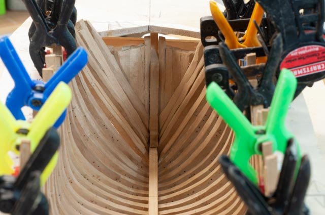
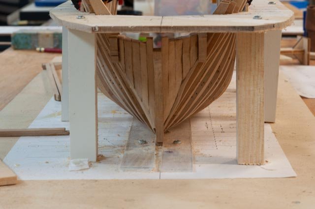
56 update on the bow section progress of the larger half brig H G Berry I am learning quite a bit here as I push through. First up I realized that the loose fit of dry fit would only get me a little way in the progress. I soon knew that I needed to commit and get the bow section fixed, so I could then build the cant frames to tie in the two sides of the gap I then realized that I needed to break up the keelson and rider into manageable pieces and install them along the way. I also found that another round of making the cant frames was in order. I went to the next scored joint on the keel and cut it through. I then found I needed to hurry up and to get about 4 more frames in place, so I could get that first two keelson sections done and the first rider in place. That first rider ties the stem together and is important. let’s see how it went 1. In this view I have cut down the keelson into its first section and tied together the forward stem assembly and the keel and it is glued 2. In this view the second keelson section is being glued 3. Here the first rider piece is going in 4. Here we see the first rider section is in and glued 5. Here was the square set up to make the stem plumb 6. Here is my next attempt at making the two cant frames 7. Here looking down I have lightly glued the first cant frame to hold it as I fix the second 8. Looking from the inside I remain mostly concerned regarding the inside sanding access once I tie it all together. 9. Here from the inside we see all forward frames in place. I have started gluing in straps to better support the frames above the jig for inside sanding. I hope it works. 10. Here is the new bow on view. I am comfortable that I be able to turn the hull over and sand these outside. Hopefully this does work out. I am thinking it makes sense to slow down and start to lay out the deck and rail lines. I have started adding temporary “ clamps’ above them to strengthen the whole thing to allow sanding before I try to install any of the real structure. All for now
-
Welfalck Thank you for your thoughtful feedback. I appreciate hearing from someone data that ties nicely with the small strings of info I have been able to gather regarding these merchant vessels. I have read tons about schooners and find much less about brigs. to you points..... • I have read that for a square sail mast 4 to six crew were typical depending on size…at 75 +/_ feet I go with max of 4 • For the larger merchant schooners it is stated in many sources to be 2 per mast, then the captain cook and mates. That 2 gets us to six • Then a cook, a captain [ often a part owner], a mate, and likely one more that could be a second mate relative etc. • If all those are aboard that would be ten. That just seems like a lot of people to me on a 75 foot vessel. I had 3 in the aft cabin and 7 forward " Caboose" • Bow ports were very common on the large schooners here in Maine. Mainers sold lots of wood. In later years it was often deck storage, but for long pine or spruce poles either from here going south or from the Carolinas going either north or further south, bow ports made sense. I have not seen them on any of the models in local museums other than on schooners. • The skylight in the photo was a 15-minute built placeholder, more for massing. It is roughly 3 by 4 feet and covers the common area. I suspect the closed in captain, mate, and head area would block most daylight, and a small openable skylight would have been likely. • The aft cabin is shown in the 112 foot Torrent painting I have, and in other models I have seen, to have a lower sole [ mid level deck 3 feet down]. One advantage is to give the captain access to the area under the after deck to store food , a wee dram and the like. Also, I learned several of the Brigs had the aft cabins go side to side, so its roof was sort of a poop deck. It would not go all the way aft and the helm and sailing area would be at the main deck level. The cabin in the photo was too tall and will be cut down. • I agree with your assessment that the best layout would leave 4 to 5 feet clear on either side of the cabin. That would on this just under 19-foot-wide vessel make the cabin only 10 feet across. If I keep what I have it is 12 feet and less than 4 foot clear either side…... As I plan to focus on a few more items, I will also make up another cabin that is smaller. Also flatten the roof, add waterboard and rails for storing boats etc. I am going to partially rationalize that for a 75-foot sailing vessel a full crew of 10 is too much and reduce that to 8 and move on. That approach should allow a better “ Caboose” Thanks again for all you feedback
-
Wefalck Thanks for the observation. One of the main reason for posting in these logs is to hear feedback. I must say with a smile that on this side of the pond , we are proud of Daniel Boone and the log cabin. I understand however they were invented in Sweden. I have been struggling all along with the size of the cabins. The " on Deck" fore cabin once decided on and reworked or perhaps totally rebuilt with water boards , maybe a flat roof of smaller planks etc, and two boats on top will hopefully fit in. The problem remains the size and trying to understand what would have been built not having any drawings of the small size vessel. There is not much information I can find regarding these early small commercial brigs [ half Brigs too] . What I have found says they had crews double the size of a schooner crew. other articles suggest 12..I think that is too big at 76 feet. There is no focs'le crew quarter like in either a whaler or a fishing schooner. That means a cabin big enough for 7 or maybe 8 to live in for a four plus month journey. It's also the only enclosed area for equipment repair, the galley etc. One choice is to ignore all that and simply scale down the cabin dimensions that are available for the 112 foot Brig to where is looks nice but then realize it is too small to house the crew. perhaps they were all "hot" bunked anyway. the forst problem is those cabins include the foremast. to move this cabin forward past the mast just won't work. it is too tight. I stated previously I prefer not to build something that doesn't work. I see no comparisons that put some of the crew below deck either. These vessels historically sailed to the Caribbean and back. Anyone with input to this quandary is most welcome. In the meantime my cabins are and will remain loose and likely the last thing to be added. I think the rear cabin size is pretty well figured out so now to consider....do I keep a rounded roof. it is about a foot in scale too tall and the sky light is temporary. As there is less to worry about I will clean it up and probably set it. I may go ahead a make a nice small fore cabin and set it in for a look see. we need two boats on its roof to hold the full crew..say 18 feet long. The big cabin now just does that. I appreciate all comments so thanks again jon
-
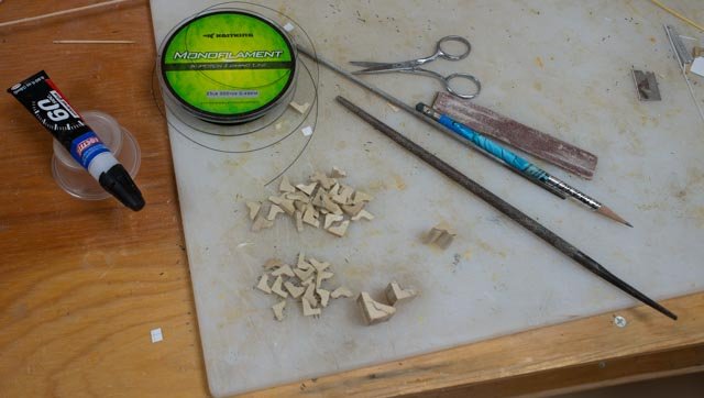
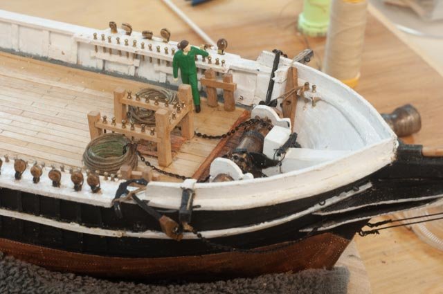
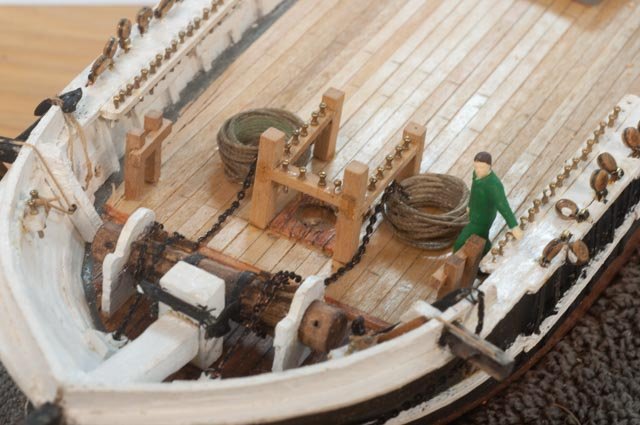
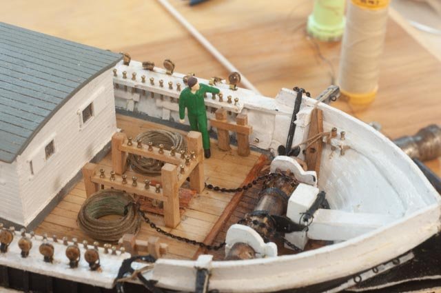
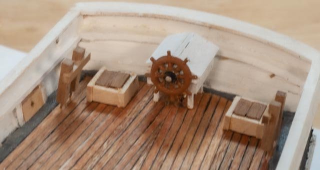
55 update on the build out of the deck….small brig I am working my way from stem plus bow sprit to stern figuring out to build and place so I can get the deck work done and be ready to set the masts. Some os straight forward and some is guessing…let’s look Here I am adding reef points to fore cousesail. I have since played a bit to add other lines. Here I have added a chain drive under the helm. Thus, I believe I need two lazarette to gain access to them. the mock ups are to move around and decide where to put two hatches and what size. I am not sure if they would have used the area aft of the cabin for other storage of say spare lines and the like…thus a bit of guess work. Perhaps they had access from inside the cabin....that is my assumption after seeing that on both Bowdoin and Ernestian similar sized schooners. There clearly is not room for an aft hatch. I also added docking hawse pipe that was not on the whaler and an aft bitts. The main sheet will be made there. • Here I have built the main fife rail and pump. I plan to leave them natural as I like the look of the Costello. I believe they would have had a simple log pump in these early vessels. There was a maker of such in the same harbor. I used brass tube for the pump. • Here I have made up a binnacle • Here with the cabin set the lack of room on a 76 foot brig / half Brig, is quite evident. It is easy to understand the act of building the aft cabin fully across the deck. I already stated earlier in the log that we know that was done on the larger Brig. • General view of the aft half Next up I have started the bowsprit rigging and the forward deck anchors etc.
-
Ernestina Morrissey by Jond - FINISHED - 1:48
Jond replied to Jond's topic in - Build logs for subjects built 1851 - 1900
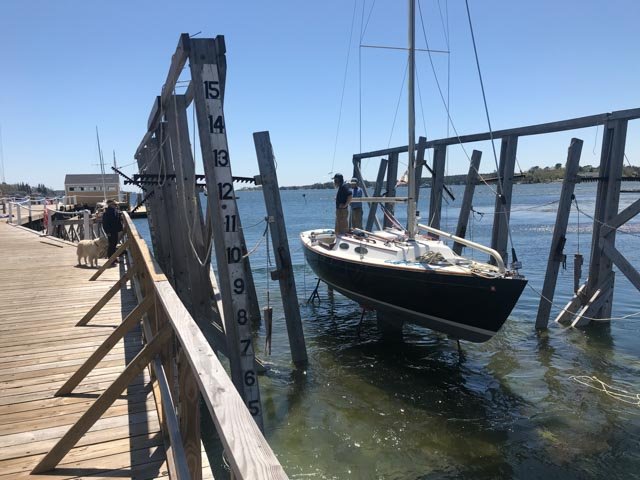
she is launched! a big step forward now to complete here rigging and learn of her sea trials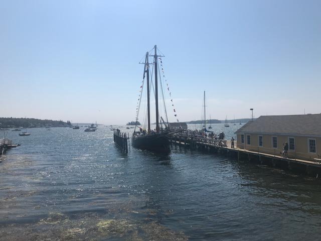
-
Ernestina Morrissey by Jond - FINISHED - 1:48
Jond replied to Jond's topic in - Build logs for subjects built 1851 - 1900
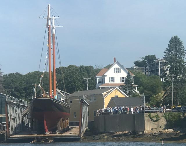
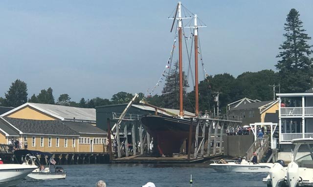
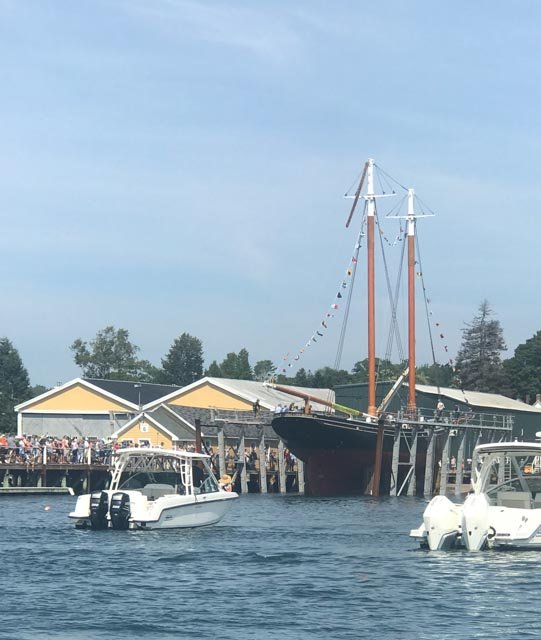
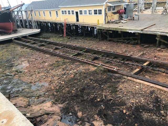
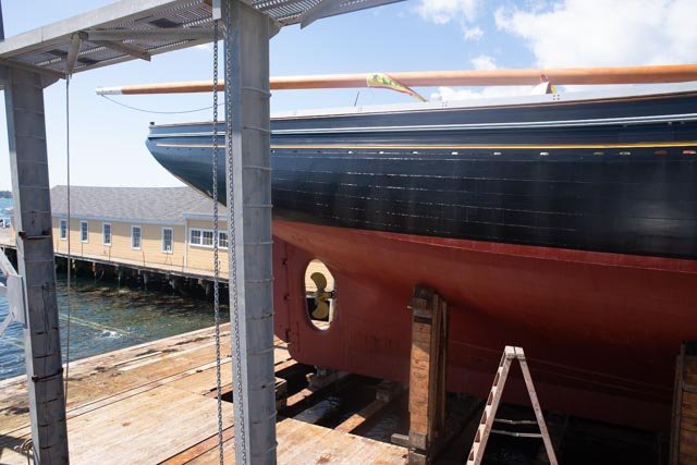
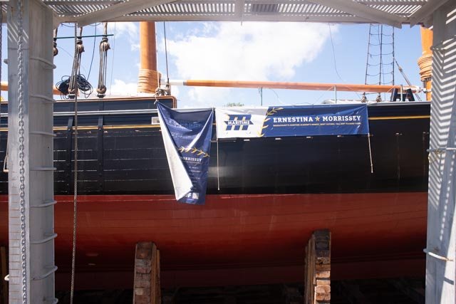
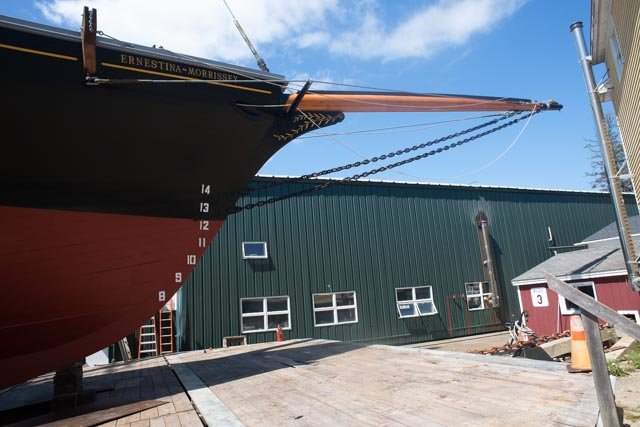
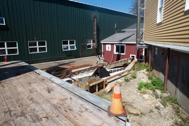
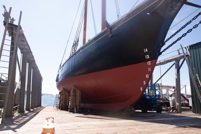
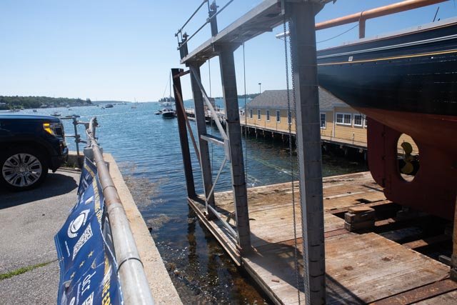
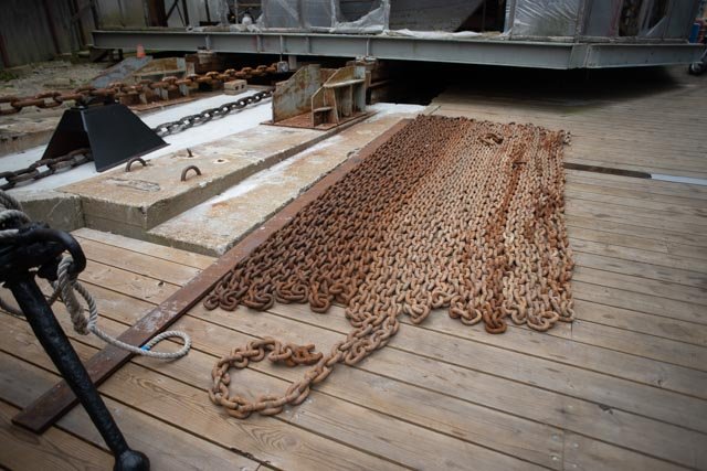
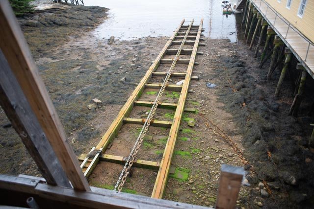
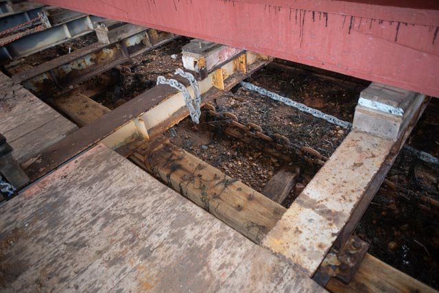
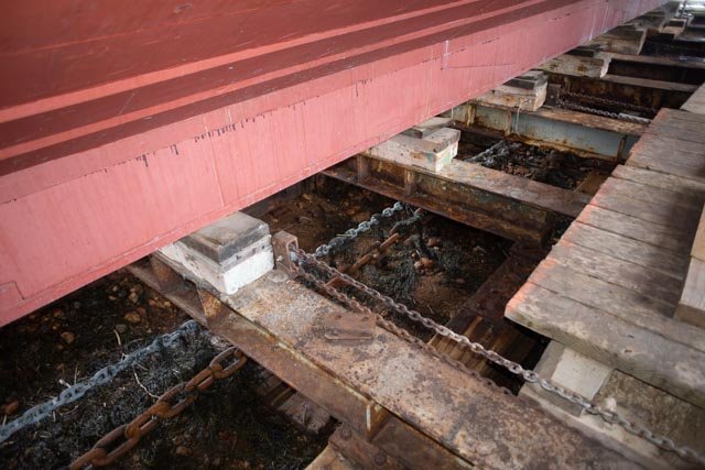
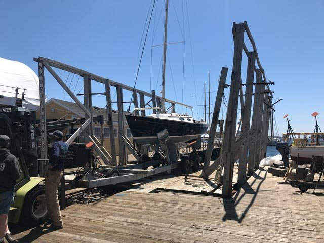
the day of the launch all started off well. we were among some thirty boats maneuvering in wind and incoming tide. 10:30. there is a land side crowd gathering and several ceremonies on deck finally about 1130 she started to move high tide about 12:30 some thirty minutes later the team must have thought "what's the rush"... perhaps better to be above to see whats happening under the water, and they stopped here we are 24 hours later. they apparently decided to go down at low tide as far as they could while inspecting everything on the way. This revision makes a lot of sense, it's just less flashy. we can see the rail and car ready for the incoming tide. here is a closer view of the roller system that rests on the steel capped timber rails. the heavy chain to pull in and the lighted chain to pull out. Hopefully by this time tomorrow she will floated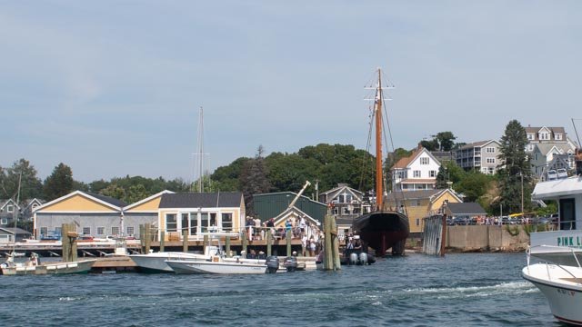
-
Ernestina Morrissey by Jond - FINISHED - 1:48
Jond replied to Jond's topic in - Build logs for subjects built 1851 - 1900
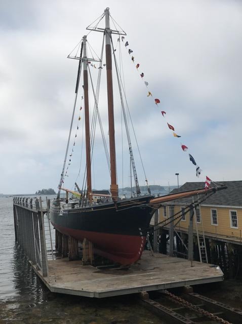
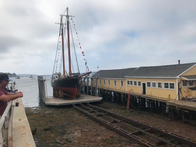
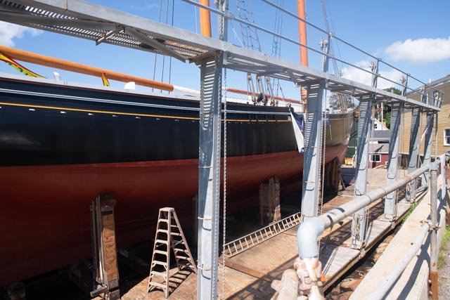
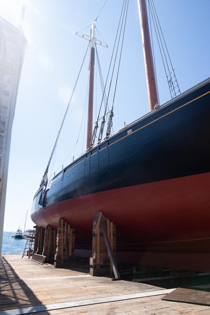
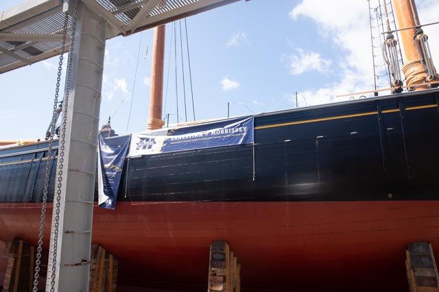
finally the day before the launch. all looks ready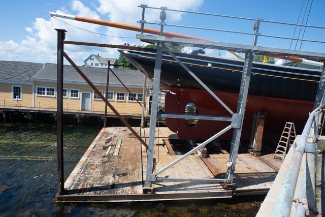
-
Ernestina Morrissey by Jond - FINISHED - 1:48
Jond replied to Jond's topic in - Build logs for subjects built 1851 - 1900
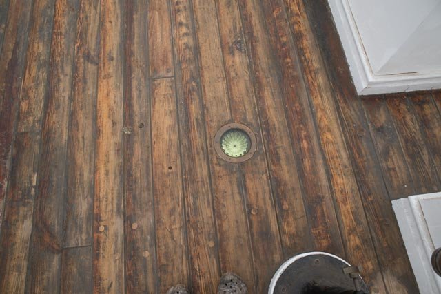
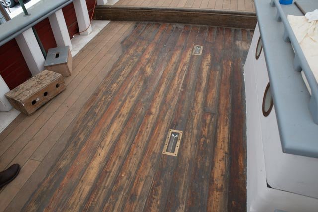
these ondeck photos were taken in May I love the prisms that made there way onto the decking. The windless totally rebuilt.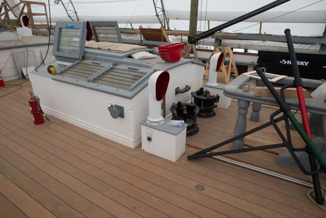
-
Ernestina Morrissey by Jond - FINISHED - 1:48
Jond replied to Jond's topic in - Build logs for subjects built 1851 - 1900
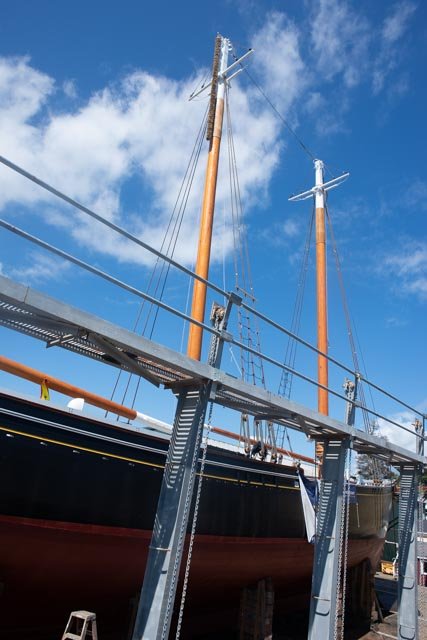
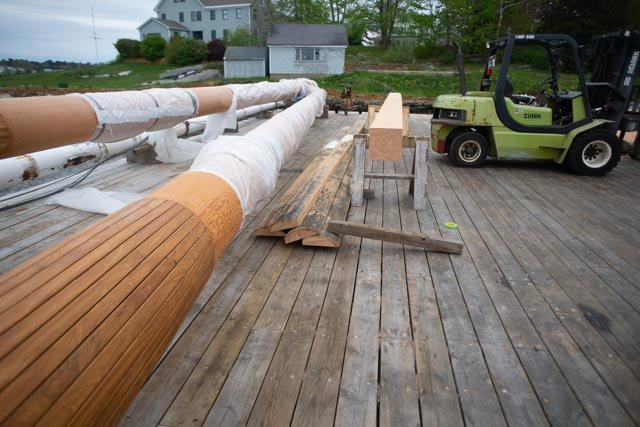
now to the masts the new larger lower masts are new. the old lower masts were cut to make the new top masts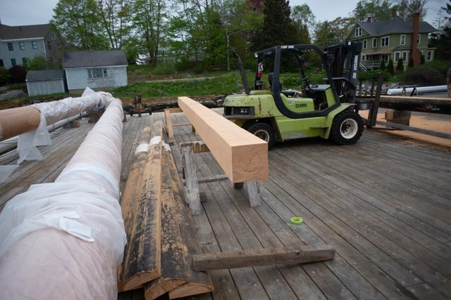
-
Ernestina Morrissey by Jond - FINISHED - 1:48
Jond replied to Jond's topic in - Build logs for subjects built 1851 - 1900
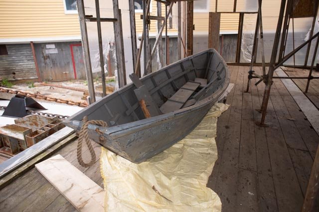
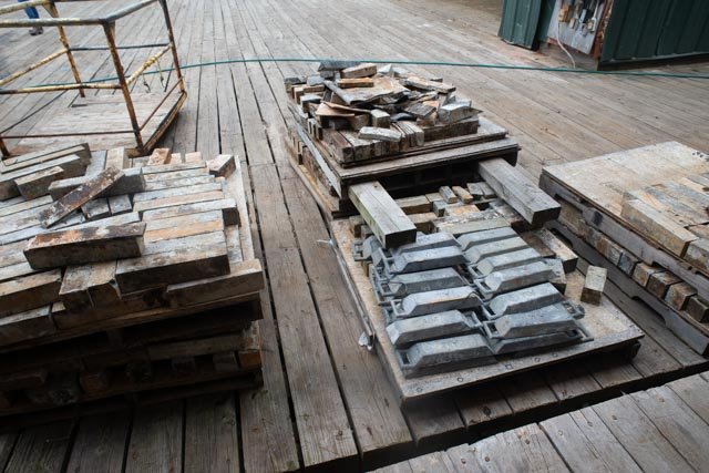
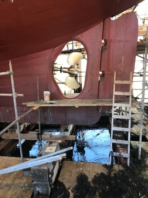
on two different days in may seeing what is going on on the railway everything has been cleaned out and turned up for the big day. the dory was a donation from a local family that sailed on her to the arctic the ballast is laid out waiting for the the installation diagrams the new prop is installed my little sail boat got launched on the adjacent railway...such fun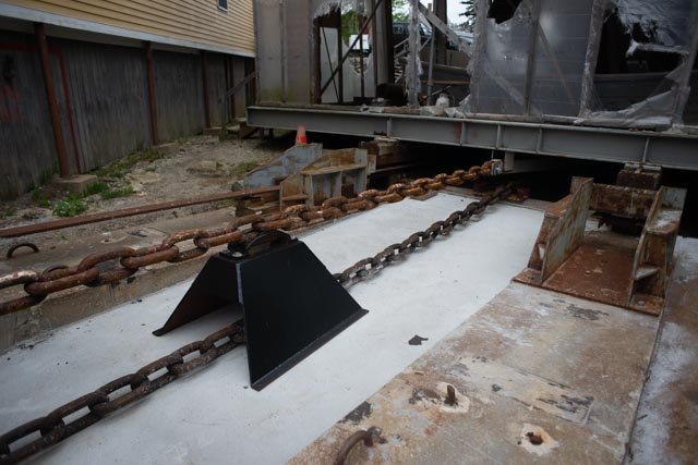

-
Ernestina Morrissey by Jond - FINISHED - 1:48
Jond replied to Jond's topic in - Build logs for subjects built 1851 - 1900
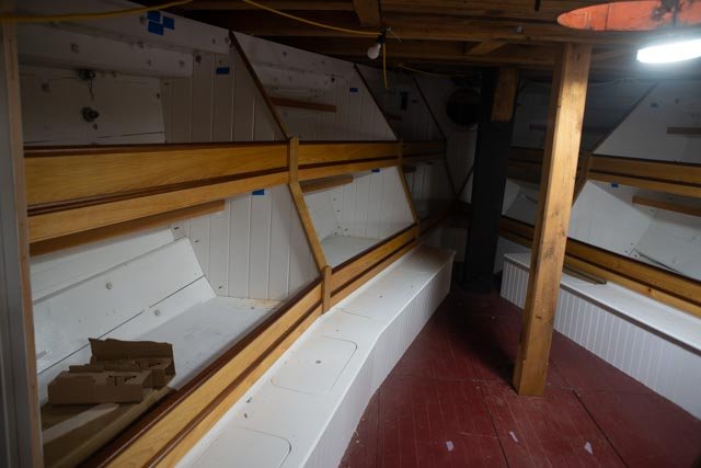
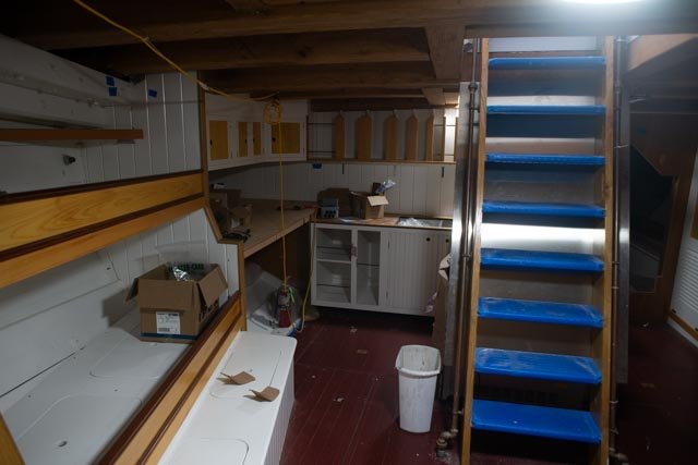
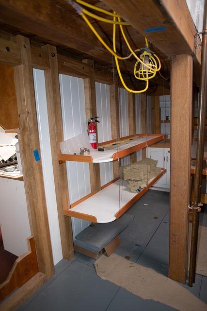
news flash. Ernestina Morrissey the real deal is ready to launch tomorrow in Boothbay Harbor a month ago i took a tour below decks to see the completed photos here is a tour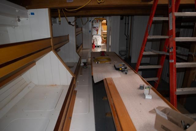
-
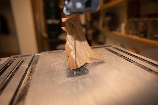
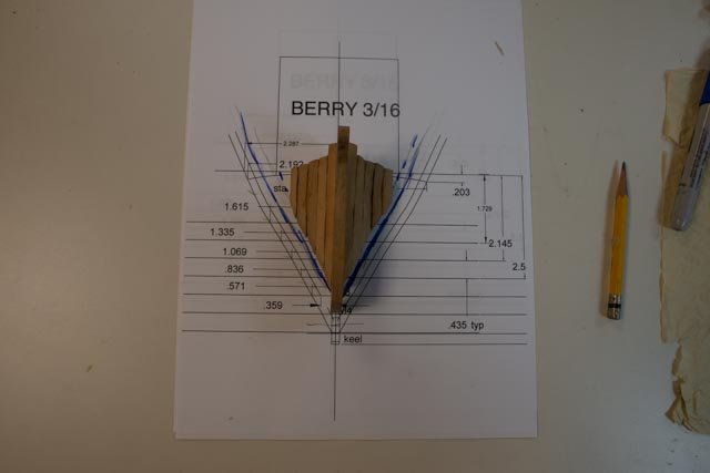
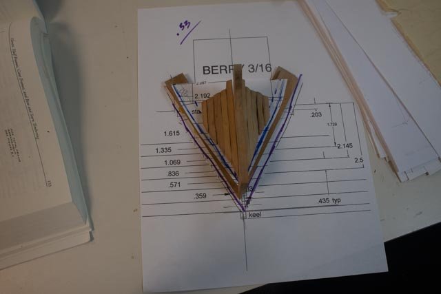
Cutting the bow stem assembly and trial fitting two cant frames. 53 Well maybe cutting the bow frame assembly back for a frame worked. I over cut it a bit with the band saw and made a little slice into the keel. I tried to fix with clear glue and sawdust. • Here we are on the bandsaw ready to cut…. • Here the bow assembly is cut, and we see it from the side • Looking at the inside of the cut piece, there is still much sanding to do, and I am concerned as to access once in place for the inside. Therefore, I think it is dry fit sand, then dry fit sand etc. • Here I have dry fit two potential cant frames and frame 1. I also went ahead and glued in frame 1.5 as it rests on the keel, and I am now confident that it will work. • Here for the side all is loose, but it seems will work out. • Here is a view of the bow assembly sitting on the frame 1 outline. There is room, I hope, for two frames between to fill the gap. The cant of them is “slight” just to divide the gap into three spaces. I will over cut them a bit as I need to turn them forward just a bit • Here the first one is made up and the second ready to go. I am not sure how I can hold them in dry fits …. that is for next week