Jond
-
Posts
876 -
Joined
-
Last visited
Content Type
Profiles
Forums
Gallery
Events
Everything posted by Jond
-

Ernestina Morrissey by Jond - FINISHED - 1:48
Jond replied to Jond's topic in - Build logs for subjects built 1851 - 1900
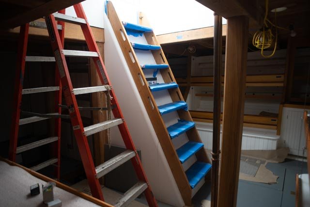
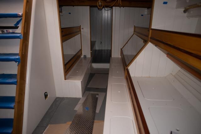
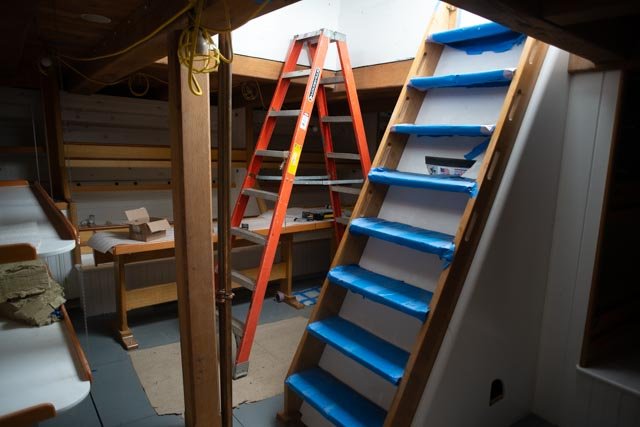
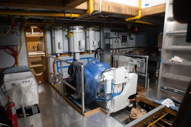
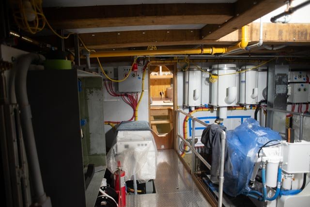
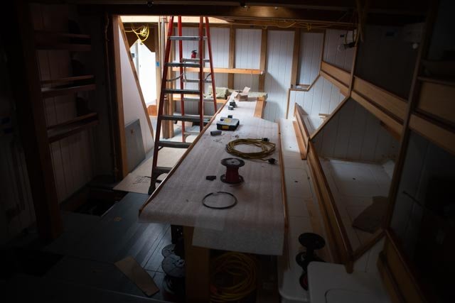
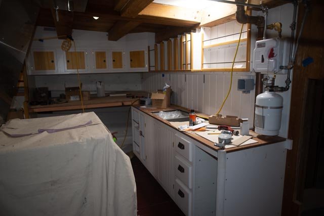
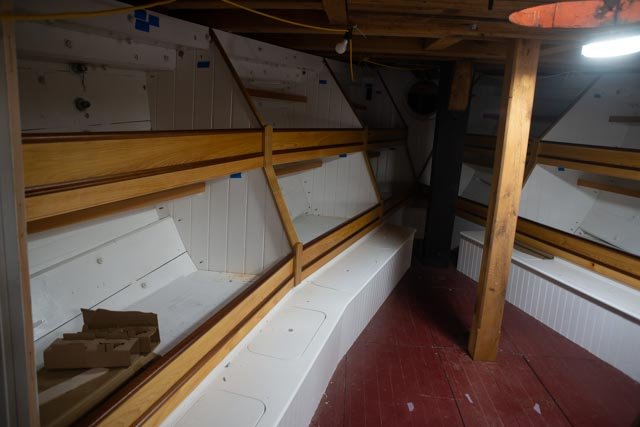
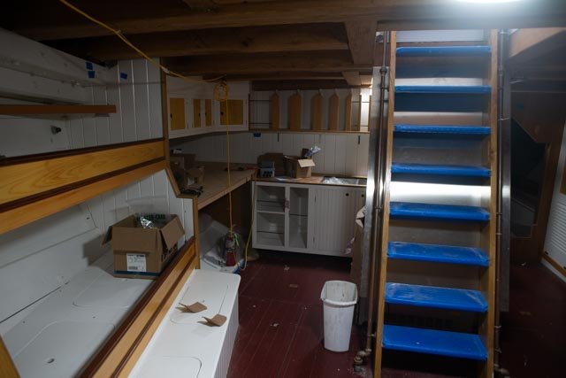
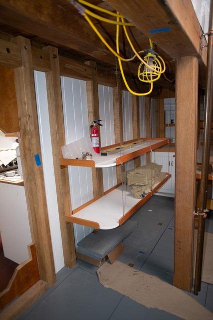
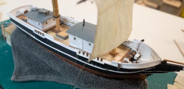
news flash. Ernestina Morrissey the real deal is ready to launch tomorrow in Boothbay Harbor a month ago i took a tour below decks to see the completed photos here is a tour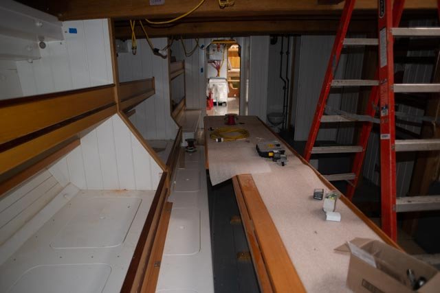
-
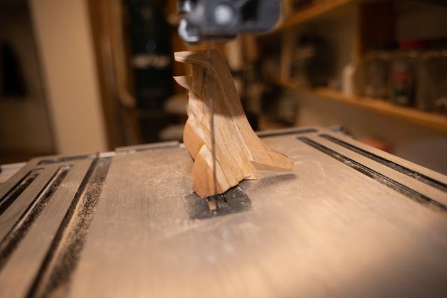
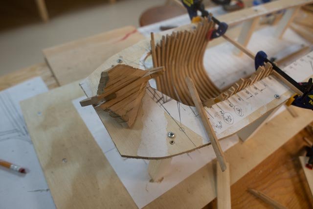
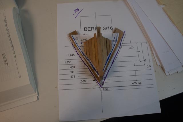
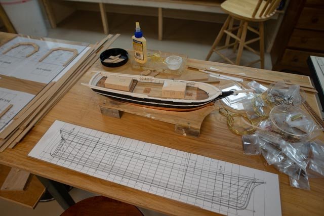
Cutting the bow stem assembly and trial fitting two cant frames. 53 Well maybe cutting the bow frame assembly back for a frame worked. I over cut it a bit with the band saw and made a little slice into the keel. I tried to fix with clear glue and sawdust. • Here we are on the bandsaw ready to cut…. • Here the bow assembly is cut, and we see it from the side • Looking at the inside of the cut piece, there is still much sanding to do, and I am concerned as to access once in place for the inside. Therefore, I think it is dry fit sand, then dry fit sand etc. • Here I have dry fit two potential cant frames and frame 1. I also went ahead and glued in frame 1.5 as it rests on the keel, and I am now confident that it will work. • Here for the side all is loose, but it seems will work out. • Here is a view of the bow assembly sitting on the frame 1 outline. There is room, I hope, for two frames between to fill the gap. The cant of them is “slight” just to divide the gap into three spaces. I will over cut them a bit as I need to turn them forward just a bit • Here the first one is made up and the second ready to go. I am not sure how I can hold them in dry fits …. that is for next week
-
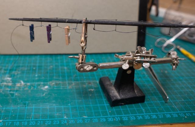
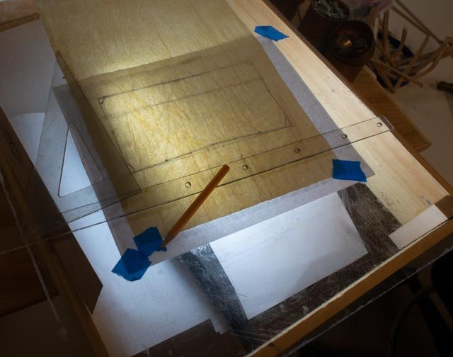
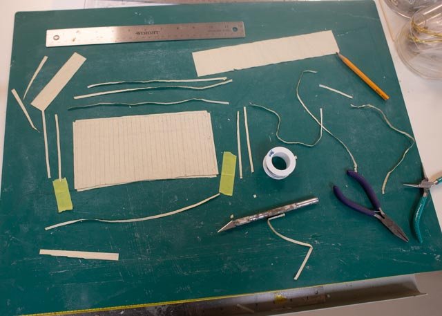
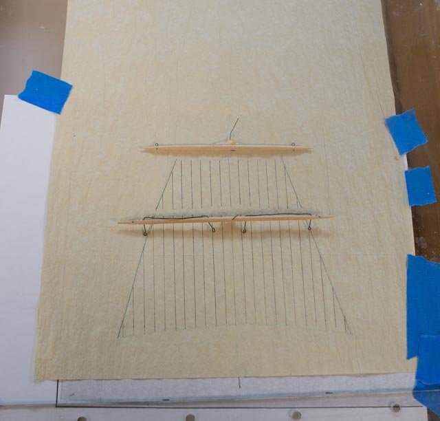
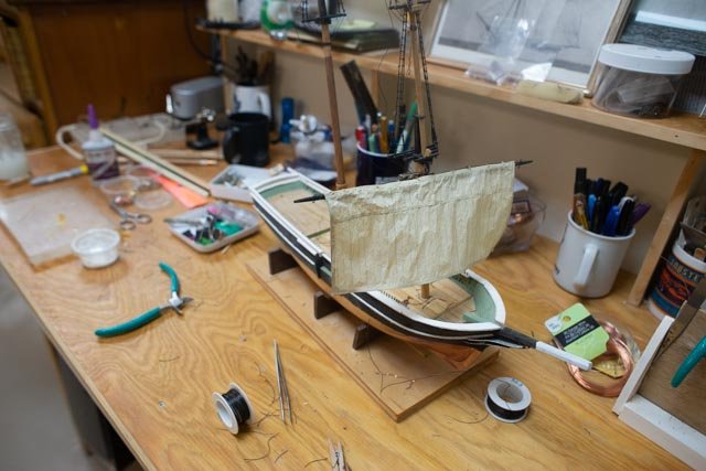
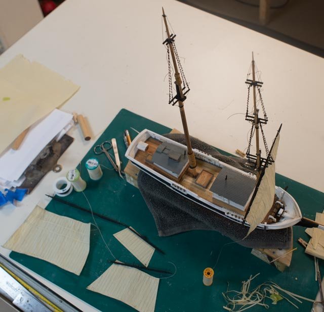
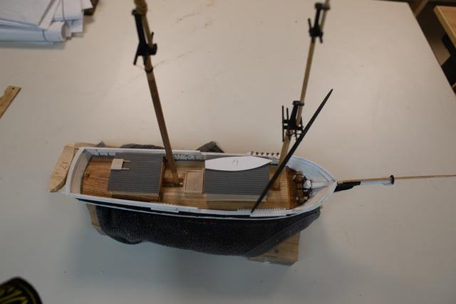
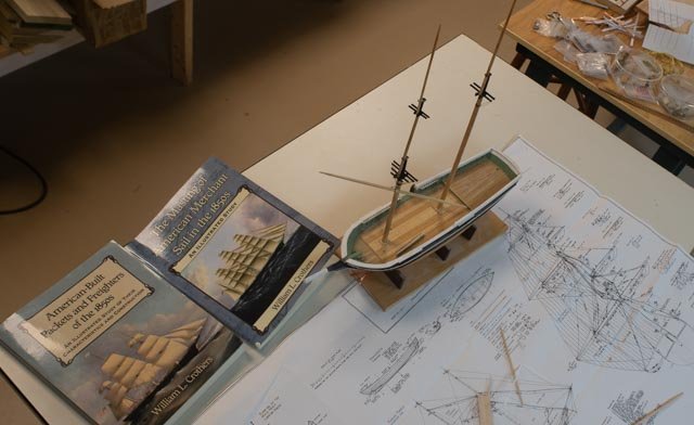
General update and progress on the small Brig……yes I should say half brig ….to be named Albert If one cares why I number photos in my log, it is because they come from different sources, and I want to be able to file them away in chronological order close to the blog. Then if I want to dive into the folder, they are easier to follow. It does take time and I am trying to find an easier way. Now I am on an apple, they make it harder to rename each one. I am now numbering each batch [ per post]. So just ignore my numbers. 54 updating the small brig sails I have tried to work on parallel paths on this build. As I am working the deck on the hull, I am doing the masts and sails, so that when the deck is ready, much of the rigging and sails are ready. I am not convinced this is easier than doing the work on the model, but it is faster and a little safter. I can move things around and not drop stuff on the model deck as I do repetitive things like tie, glue and cut ratlines. The following sequence includes some of the work I have done this month. • Here I have trimmed out the yards. This view shows my attempt to add wet white glue and weights to shape and hold the foot ropes. • Here I have traced sails from the Cate Cory plan. I have left over painted silk span from the last build that was a bit messy. I like that feel of older rougher canvas for a sail that is on a working half brig. • I built a light box and traced the lines onto the silk span • Here we are with the first one cut out and strips ready for assembly. I am using thin annealed steel wire around and thread on the head of the sail • Here is a step I learned the hard way. Model sails tend to grow. Therefore, it is a good idea to take the model spar and as I did here cut the sails down just enough • Here again I am tracing out the lines. In this view one can see I tried hard to make the back-to-back lines just a hair apart from each other so if one can see through the sail it looks like a double seem. I did it but I cannot see through. • Here I have set the first sail on the trimmed fore mast. I am working on a spare hull and therefore dropsies don’t matter. I am debating if, or if how many lines I add before transferring to the model. I think the lifts and sheets for the yards and sails make sense to do here • I moved the trimmed masts over to the main hull for some progress pictures. The masts have their shrouds and ratlines. Next up is all those little blocks. • Here the deck work is getting about halfway. I need to figure out fife rails, and the rigging plan next, make a pump, complete the helm, add bitts etc. I did cut down the cabins some since i last shared them. All for now

-
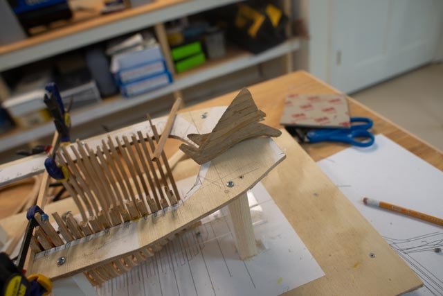
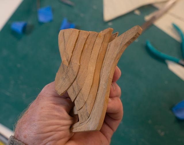
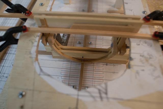
Now back to the bow Here in my hand is the assembled ‘draft’ stem plus knight head plus four hawse pieces. What to do next? • Here I sanded back and tested a few times and the pencil mark shows where I believe I need to cut it back and replace it with a forward cant frame • Here miraculously the other side is almost the same • Here looking down on a loose dry fit, it seems that the square frame 1 will end up going in as planned. I am thinking two cant frames will make it all work • In this view I see in the photo that the two loose frames, 1.5 and 1, have slid back a bit. With them plumbed, there should be just room to make the two cant frames. Now how to make them….the adventure continues how can I cut that and make it presentable. Will this attempt be just a draft? We’ll see

-
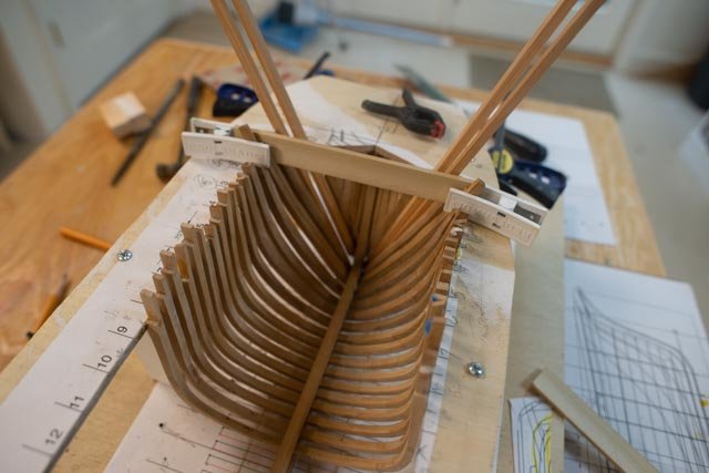
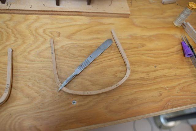
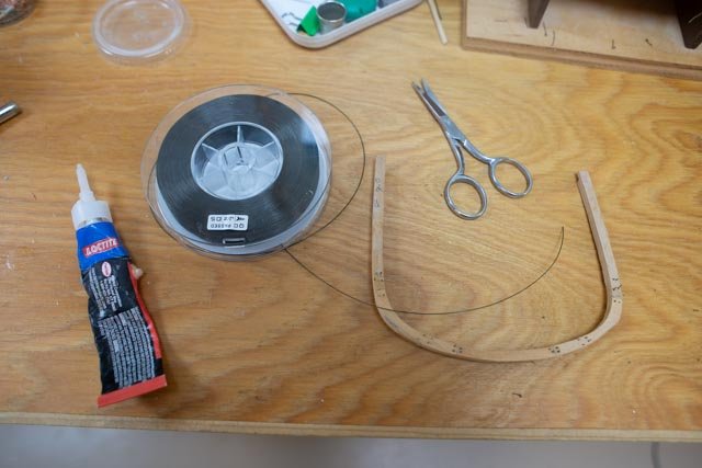
To complete the above sequence, I record a few more views of the frame assembly To complete assembling the frames I have made a new change. I used to use copper wire glue through a hole, filed smooth and then darkened with Liver of Sulphur. I saw a trick somewhere of using black monofilament. After finding no black in any local fishing or hardware store, I made some exchanges with an internet site to learn what the 10 lb vs 30 lb test line diameter might be. I landed on 30 LB was the same as gauge 24 wire, then alas …”out of stock”. So, I settled om 25 lb test and it works ok. Before this next step I used a little water on the paper cutting guide and the edge of a chisel to scrape away the white glue. I then used a Dremel and some hand sanding to improve the shape of the frame prior to drilling those roughly forty holes for simulated bolts. • Here I am using a general glue as I fear the AC will eat the plastic • Here after experimenting I found a new scalpel blade works best to cut off and scrape any glue residue. After this step I will fine sand the frame before installing In conclusion I want to admit what I am not doing ,that I am amazed to see the real pros do. The real frames on larger ships according to Crowther’s were stepped. I.e. the first “floor “of a 12 inch frame might be 14 “ wide and deep and the first futtocks 12 inches. Then the subsequent futtocks or top timber stepped down in both directions as they reached to top. Also, there was more science to the location of the joints. In my previous build of a 100-foot schooner, I knew as I was copying the real vessel, Ernestina Morrissey, that the frames were all consistent, so stepping was not necessary. In this model I cannot tell anyone what was real in 1840. However…this is a 112 foot vessel. Not that much different than a schooner, EM was of the same size. This is not a 200-foot ship. So perhaps my short cut of making all the frames 12 inch all the way up may be accepted. next up more on the bow
-
Allan thank you so much for your kind words. Yes each build to me is much more than the model. The build is an adventure. My talk on the history of the Boothbay Shipyards, first 100 years is on the 25th . I will share a few more points from it in the log here afterward as they relate to the build of these brigs. I will call that brief bit ....brigs of Boothbay. this afternoon we are having a tour on a historic vessel around the harbor and I will share that too. I will send you the link.
-
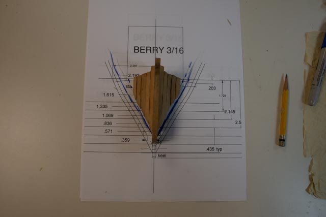
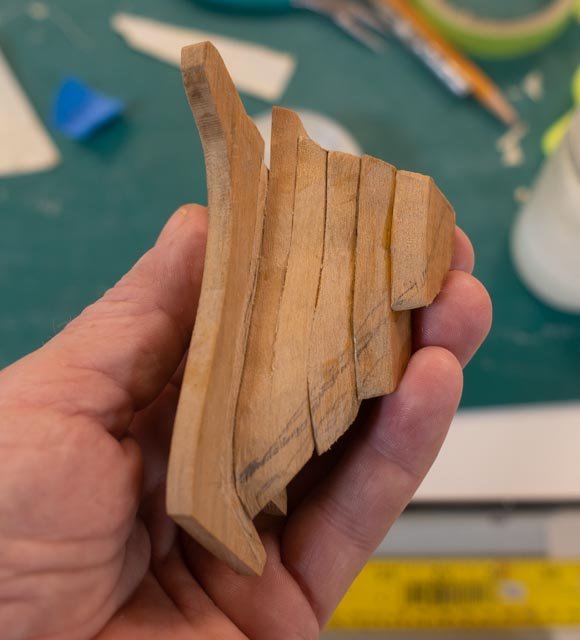
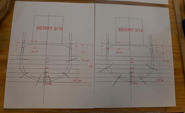
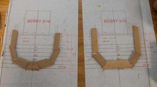
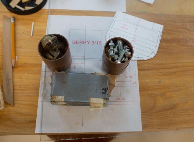
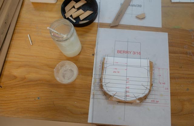
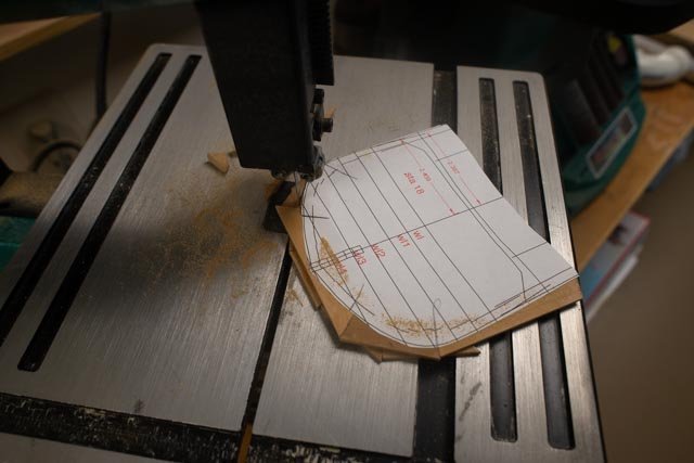
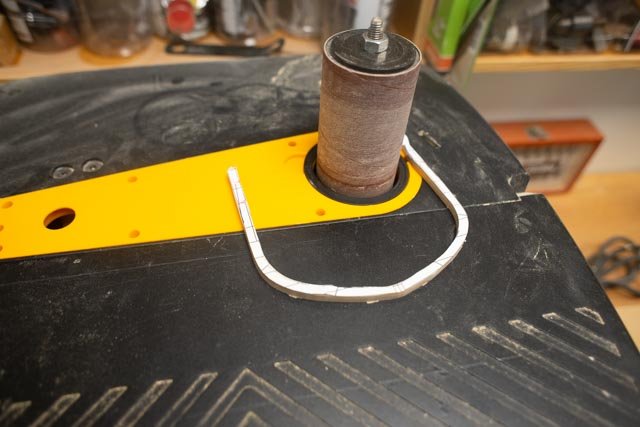
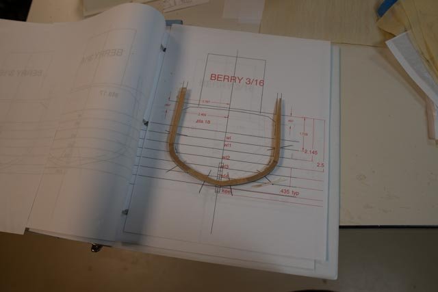
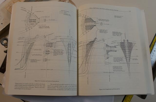
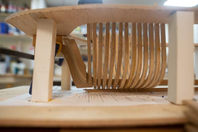
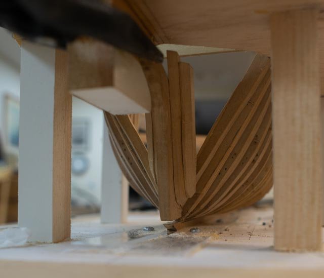
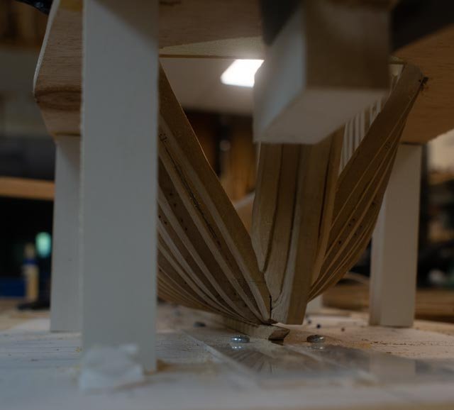
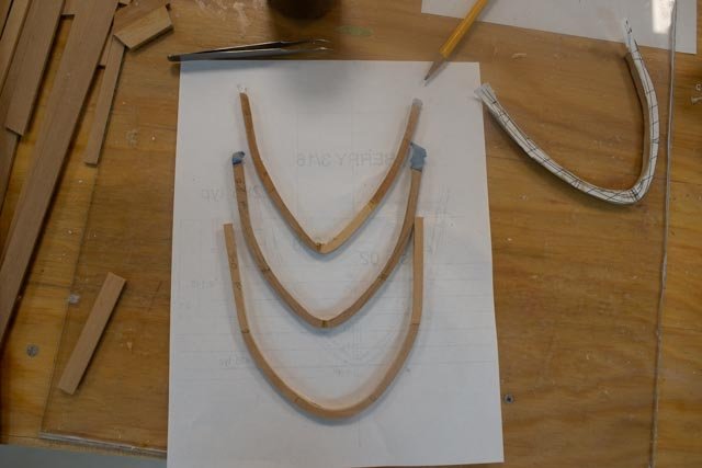
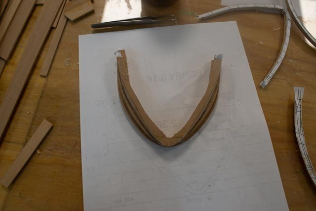
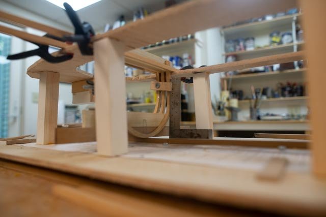
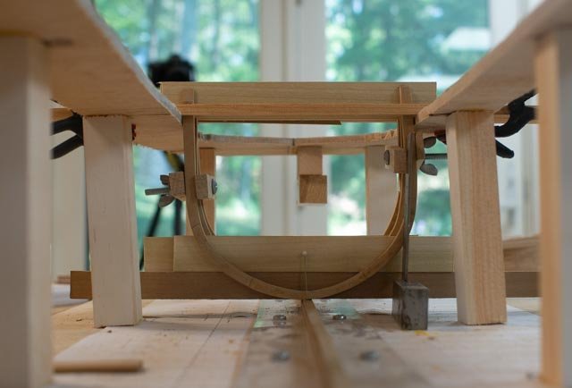
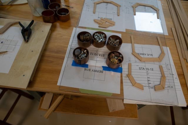
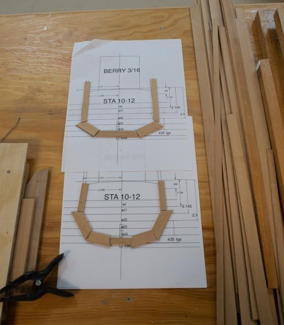
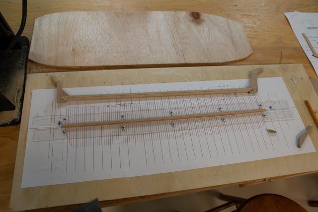
I thought that for encouragement of other learners like me, I would put together the sequence of a frame. This is no museum piece, but it is fun to try to make bones, and I encourage others to try. This build is my second attempt. The following photo group is the first half of a frame sequence. Two prints of the TurboCad layer “frame 18” with pencil marks for joints to be set under plexiglass sheet Cut out 3/32” by ¾” or 5/8” strips of Costello with butt ends glued Two half frames glued together One copy of print cut out and white glued for cutting …lining up with other Rough cut Outside shape Inside shape Sometimes I lose the ID label or keel marks. I keep the second print out and find several times it’s convenient to check back in, so I keep them. _____________________________________ The bow section is tough already, but with absolutely no predrawn cant frames it is fun. I have no idea if this method will work, but here I go again The following view shows a progressive idea. First is the book by Crowthers showing us how the bow was to have been framed. The key for me is two knight heads and four hawse pieces 12” on either side. In these views I have roughly shaped the knight head and one hawse piece on either side of the stem and tried to dry fit it. Frame 1 is loosely set in place, and I am going to make up more hawse pieces to try to fill the gap. I have rough sanded using a Dremel, but don’t dare get over aggressive yet. I have no way to say that what I am doing is accurate as there are no plans for me to follow. My approach may work, we’ll see. looking forward see the hawse pieces glued side view...not a lot of room for cant frames. front view starboard bow view looking at the pages of the Crowthers book on framing the bow
-
thank you Wefalck for your sympathy...I am surely learning by trial and error. But having fun thank you Allan I downloaded and started reading the article. I am OK through the first 20 pages. let's see how it goes as he gets into the real deal I am also trying to find black monofilament to use for bolts, since I found I can see them. the copper wire and trying to darken it is a pain. Now I am getting to main area where they will be visible it becomes important. thanks for the suggested reading FYI Ernestina is planned for launching this month. I'll post and update when she does cheers jon
-
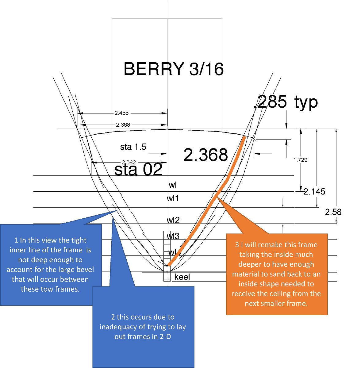
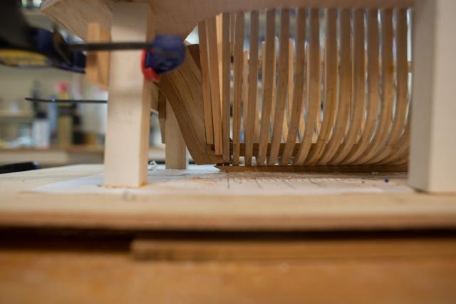
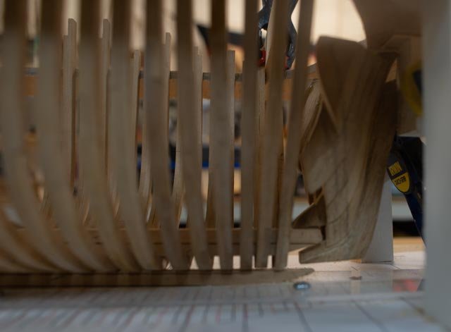
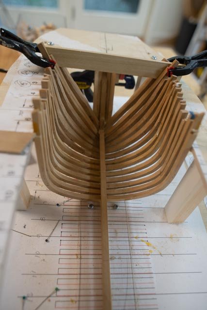
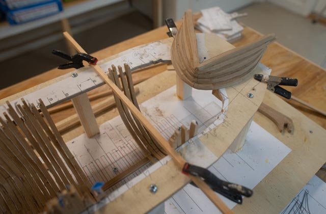
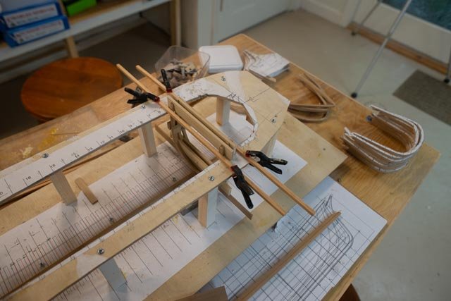
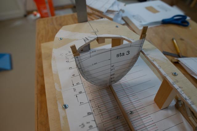
The first frames are glued! This story is more a saga, as I find my way through the fields of trial and error. I am using 2d cad only and trying to make frames…tough to do when we get to the bow area. 40 here was my trial which ended with oops. I just kept rough cutting the frames thinking that the slight bevel at the top of the jig meant something…..it did not here are three frames that need to be rebuilt with a little planning. My effort follows 41. here on the plan to remake frame 2. I turned on the layer for frame 1.5. I then used seat of my pants judgement to decide where to cut the inside 42 here is my first trial starting at frame 3. 43 here are the first three rough cut. That means to me as far as I dare go with power tools 44 here is the stack cleaned up. In the end I made all five twice and two if them [ sta 1 and sta 1.5] three times. I assume that with my methods I will still need to sand after I get them in place, so I left them just a bit heavy. I also used this time to drill and place 24-gauge copper wire to simulate iron bolts and used liver of Sulphur to darken them. I doubt they will be visible but would hate to find out later they are and find I didn’t have any. 45. Here is my self-made jig. I milled out some planks to use as spacers, and hope it works. 46 tada!!! My first three frames are being glued to the keel and jig. The jig, at 4 inches above the keel, is about an inch above the future deck. 47 I am lucky that the clamps I made up for the last POF build are small enough to just fit through the smaller scale spacing. 48. the first view of what hopefully will be a progression of shots, as the work progresses aft. Next up I am working away at the mast trim out and deck work on the smaller brig and want to get the frames going forward on the big brig in place and figure out an approach to install deck frame clamps to make the structure secure as I move aft.

-
Wefalck well said thanks
-
Rick welcome from another mainer. we have a group that meet up in Bath and would welcome you. My recent reading included chapelle and he described the snow as did Wefalck to be rigged with a smaller mast, whose top fits into the cross tree as it sat behind the lower mizzen. Think of the large diameter of the main mast on brig or mizzen on a ship and the challenge of the yokes of spars and a lower square sail. I believe the snow was limited to brig and have read the name spencer mast when reading about a ship. I am sure you know the penobscot museum well. We had lunch in Belfast while up there..a great town. cheers
-
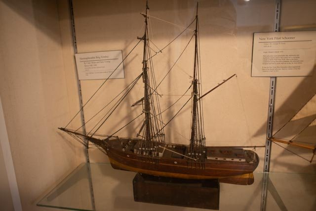
Wefalck first thanks for your response above. I went up the coast the other day with summer visitors to the Penobscot Museum in Searsport, Maine. I had not been in several years and it was fun to see the collection of models and paintings. I wanted to increase what I had on Brigs. There was a wonderful example display titled hermaphrodite brig so and so that gave even another explanation. It agreed with me that there are stays on the mainmast so gaff rigged fore is nuts. They have spanker directly on the main mast....no spencer mast or snow rig . I laughed and wanted immediately to share it with you with you agreement that some subjects have "alternate facts". It seems alternate facts are an increasing popular event over here on our side of the pond. this view belongs to the Penobscot museum. it is close to what I think I will be modeling back to the subject ..I appreciate your suggestion of ...lets carry on cheers
-
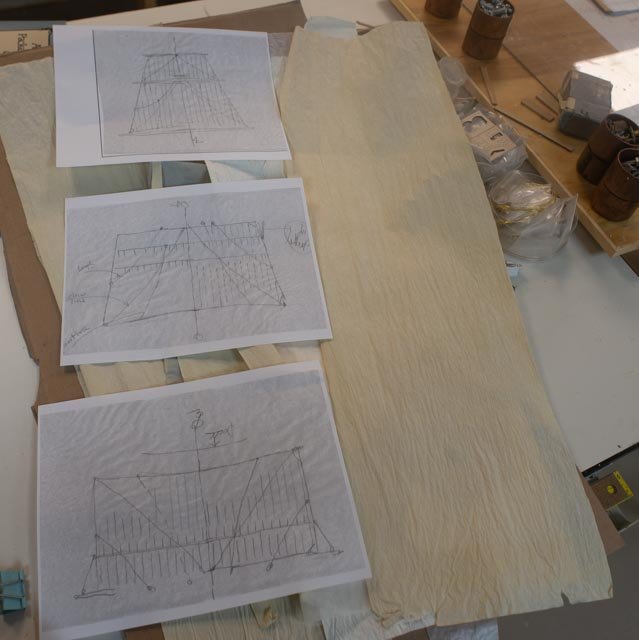
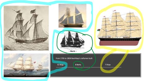
Wefalck, I am honored at your visit….sorry for the abbreviations and calling all a brig. You are absolutely correct. According to my studies there are three brig configurations. Then there is a fourth short name local to Maine. I also take issue with standing rigging …see below .... you can tell this topic is much on my mind. A quick look at a dictionary online: I would also point out that if you go to more sites you can find more disagreements too. hermaphrodite brig from oxford languages 1. a two-masted sailing ship with a square-rigged foremast and, on the mainmast, a square topsail above a fore-and-aft gaff mainsail. ** brigantine. 2. a two-masted sailing ship with a square-rigged foremast and a fore-and-aft-rigged mainmast. ** see my comment below re foresail. I believe that definition is wrong because the need for head stay [s] 38. Please see a slide from my upcoming lecture on Boothbay shipyards…..the talk is more about who were there, when, and what vessels they built than any highly technical stuff. The images are off the internet. In the view on the left we have: 1. Lower left…full brig. Squares on both masts 2. Upper left. Hermaphrodite brig. Where one square sail is on the main mast and staysails go forward, as there are two, a lower main stay and main topmast stay, that would interfere with a fore sail. Note I prefer this view that disagrees with the dictionary definition! 3. Upper center. Brigantine. I question some of the images here. A Schooner rig has a jumper stay that is lower mast top to lower mast top and no head stay on the mainmast. As a foresail is shown, it makes no sense to me that a main lower mast head stay be shown. I am still looking for more images so that I can be more comfortable to model a foresail with boom and gaff. if such a stay is there one can only sail on one tack. 4. I read last winter that in Maine, during the 19th century, the Brigantine was called a half brig. Surely the logical thought could be half brig half schooner. The discussion of the standing rig configuration probably plays a part. I would love to learn more about where the variations may have taken place. I am stating what I have read, not what I know. My reading here tells us, full brigs were early and two that were so launched were soon converted to “half brigs”. The prevailing southwest wind on the East coastline made the half brig [ brigantine] popular. Also it allowed smaller crews. We also know there were many topsail schooners built here as well. It seems there are many blogs, books, and samples regarding naval brigs, and they were often shown as full brigs. I find very little information on these merchant vessels. They seemed to stop in the late 1850’s. After our Civil War, the US ruled only domestic bottoms for interstate commerce, and the boom in building bigger schooners began. Again, thanks for dropping in and I would love to hear if you could share more info or suggest any references. Jon
-
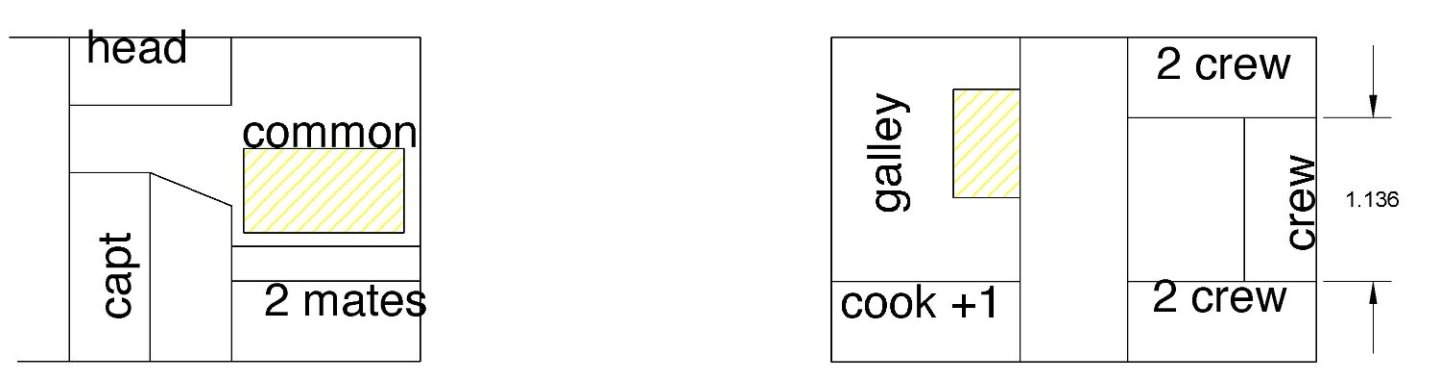
Keith I am always pleased when you drop in and gently shove me in the right direction. I have since cut the fore cabin down to where there is reasonable deck access, but still enough room to carry on all the activities needed to be inside a deck crew cabin. I assume in cold waters that to mend a sail, splice a new line, mend fittings, cook, sleep when possible for say 7 crew that 12 by 14 will have to do. I also believe, but have no good source to support my felling, that the crew must have been reduced to no more than 10 when the Brig…..brigantine. was only 75 feet long. I have been reminded that even today, as in this summer, 5 adults sailed in a 32-foot sailboat for a week and no one was thrown overboard. Thanks
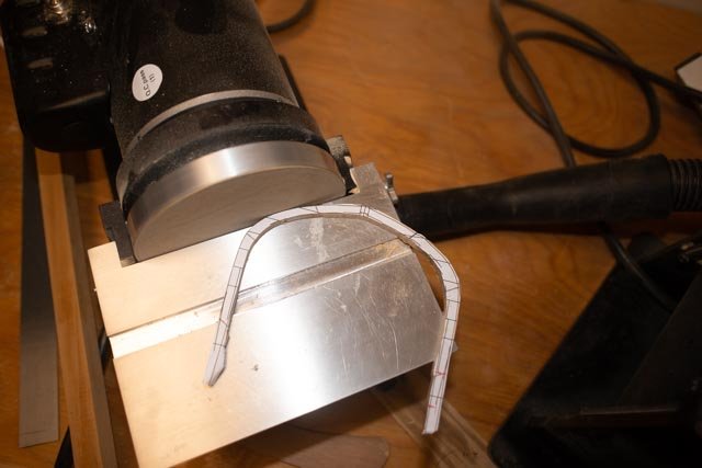
-
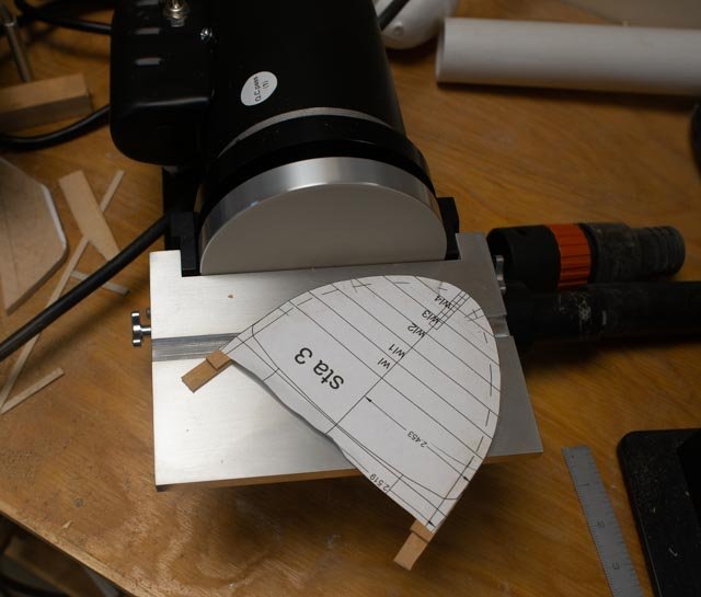
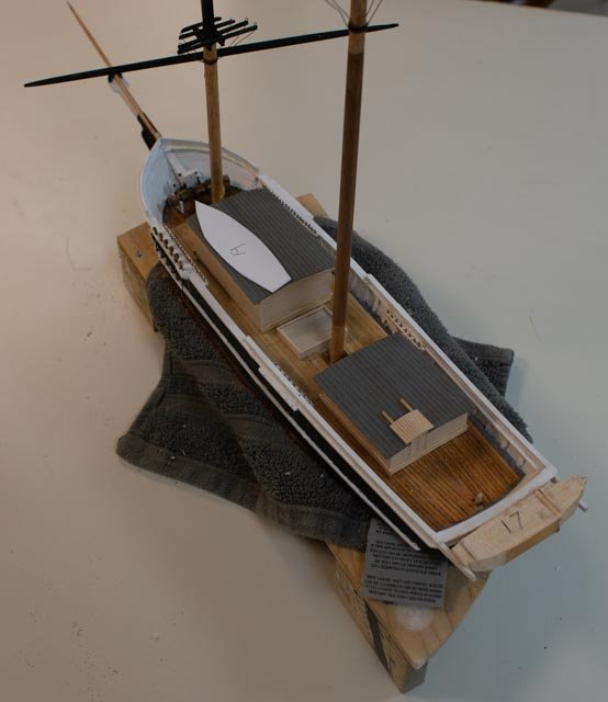
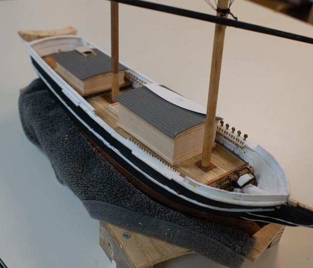
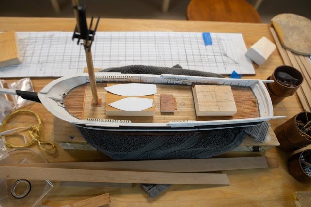
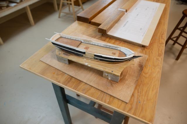
It’s time for my first show and tell at our Downeast Shipmodeler’s guild monthly meeting. I got things ready for the local group critique and went off to Bath. They were kind….truly as the small brig needs lots of clean up. One smart guy said....hey that looks like one of those kit whalers........ Small Brig 32. in this view we see a few more changes. I have roughed out two deck cabins, the hatch and shown the plan to store boats. I am starting with the cabins as a similar size as in the painting of the 112-foot brig. They look too big, but I cannot shrink them too much, as they need to fit bunks galley people etc. 33. I have also roughed out the windless and hatch and placed the first dead eyes. 34 this view shows placement of the aft cabin works. I have enough room to squeeze in the helm, a lazarette, bitts and binnacle. There just is not enough room at the midship hatch, so I will shrink that cabin a bit. As to the boat on the stern, I am still wondering about the whaler designed tail feather to support the smaller boat aft. As of now they are coming off. 35. surprise. I have treated myself to a new Byrnes disc sander. Wow it is a great addition and will surely improve my work. Sanding my first frames was wonderful. It will take some learning to get the bevels right. 36 here we see the first fully sanded frame. it fit yippee A final check before I move ahead with the cabins 37. In this scaled sketch based on the painting of the larger brig, [ and the width reduced to fit the smaller brig…12 ft]. the fore cabin is 18 by 12 feet, and the aft cabin is 13 by 12 feet. A theoretical combined layout shows bunks for 3 in the aft cabin and maybe 7 forward. My plan is to move ahead with the cabins. The fore cabin will be reduced about a foot or too in scale to make the deck hatch access seem more reasonable. The boats I have chosen to use as of now are one at 17 on the stern and one at 19 feet on the roof. One at 19 feet just clears the shrouds when rigging off the roof. Now back to work...all for now
-
Continued with the small brig on deck and the large Brig frame building reviews. Small brig Like many experiments, when they don't work out, I have gone back to the drawing board. Another oops happened with the main mast location on the small brig. In the study I described above, the Crowther’s book described placing the main mast at 10% boat length behind mid-point. Despite that recommendation I was satisfied then to keep the Kate Cory layout…just a little back of midpoint. Well, that did not work out. 30. In this photo I have moved things around, and found that to get things in and to look like several other brigs, I need move the mast aft to a point 10% behind center, I then have room for the center hatch, the forward cabin, a pump etc. [this move will impact the sail plan slightly as it will likely shorten the boom accordingly. We’ll see when I get there. I also need to decide the size of brig’s boats. Many whalers had “tail Feathers” sticking aft holding a spare boat. I do not see those in the images of the merchant brigs. I have yet to cut them off this hull and will study a little more, but I think they need to go. I learned in an earlier build that following Lloyds rules, this size vessel only needed two boats. I assume both would be rigged above the forward cabin when offshore. I am currently showing one at 18 and another at 14 feet. [ that is work in progress] I suppose I should be adding some tackle lines to show how they were handled. Again, we will see later when we get there. Large Brig On the large brig, I have the jig loose but in place and am starting to check out frames. This will be a long straight work program to get enough of them made and checked, so any adjustments made to the gig can be done before I start. As an example, the frame shown fits fine. The few behind it need the jig to be sanded back a bit. 31. This view shows some progress with one frame that actually fit. more coming
-
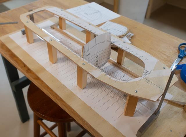
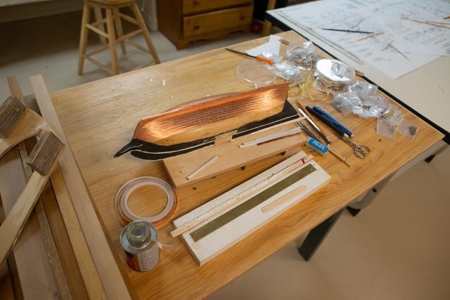
Post 5. Actually, getting started….maybe I find that those of us in Maine get invaded every summer by family and friends looking for the sea. Of course we join in with them. That means a few false starts are involved with all planning. So be it…June was a little progress. 22 here we see the mast assembly for small brig progressing, so they will be ready when the hull is fixed up. 23. here we see the keelspan, stern post and stem assemblies being readied, and the keel set on the building board. 24. here is my first frame being cut out for glue up. 25. I am not very good at copper tape. I have found that I need to use contact cement to get it to hold. 26 I am slowly getting my production sequence up and running for all those frames. I am using a sheet of plexi glass and slide two prints of the frame under, so I can slide around and glue up the pieces for the two halves. 27 here the copper is done for the small brig and now the topside of the hull and deck need attention. I have lots of clean up on the paint etc. and am now experimenting with the layout of the deck. The blocks are experiments in form. The deck houses?? The paintings I have of the two local brigs show the main cabin going rail to rail. I get the logic of it, example how does the owner /captain and or family sail without an enclosed head? The vessel is not big enough to have one forward as did the ships of the time. How is that done without the cabin reaching the side? The small brig at 75 feet does not have much space for crew deck house. Using proportions now I see the small structure. It seems easy to find sample plans of naval brigs of the time. It is the commercial ones that I am struggling to find. 28 I mentioned before the challenge of learning to use tubocad on an Imac as part of this build. It is coming along, as I am sticking to two dimensions and leaving enough wood for fixing. The Costello wood [ new to me] seems very easy to work with, so I believe careful sanding will work. If not, I will be in trouble. 29 The next trick is to decide which method to set frames. The easy way is to have a jig that sits above the rail height and receives the extended frames. Once they are in internal ceilings and shelves / deck beams etc. are set and all is good, off comes the jig. I am starting off thinking that is my method. I took offsets from the frame drawings and roughed out the plywood jig. We’ll see how it goes.
-
dear K I just saw this posting last night in a list of recent postings on the maine page. I share that as I suspect i am not alone in not checking past building logs. The emails notifications seen to go directly to spam. I looked on google and found a few sites that sell new plans for this kit. they are quite extensive and if you need to know part number reference helpful. they are quite informative regarding the rigging too anyway. good luck. here is one of several sites. I suggest you compare and also look on ebay and similar sites https://www.cornwallmodelboats.co.uk/acatalog/Mamoli-plans.html
-
dear Dupiop2 sorry I just saw this posting last night. I had set this build aside 4 years ago so I do not check this log. Anyway sorry not to have seen it. I had to rummage around to find the old plans and find out your question...step 6 and the 3 parts. Pure based on four year old memory...... I think your question related to the little challenge to set the counter section that may have been called the " transoms' in more modern 19th century. take a look at my posting 4 above and you see that part 24 is made up of 4 pieces that fit against the bulkhead. 22 sits on top outer edges and defines the straight run of planks. 21 sits below and defines the bottom of the planks I hope this helps. the instruction I have are in Italian and I do not read it, so for me it was based on following the pictures only. I am not sure when I may get back to working on this build. good luck.
-
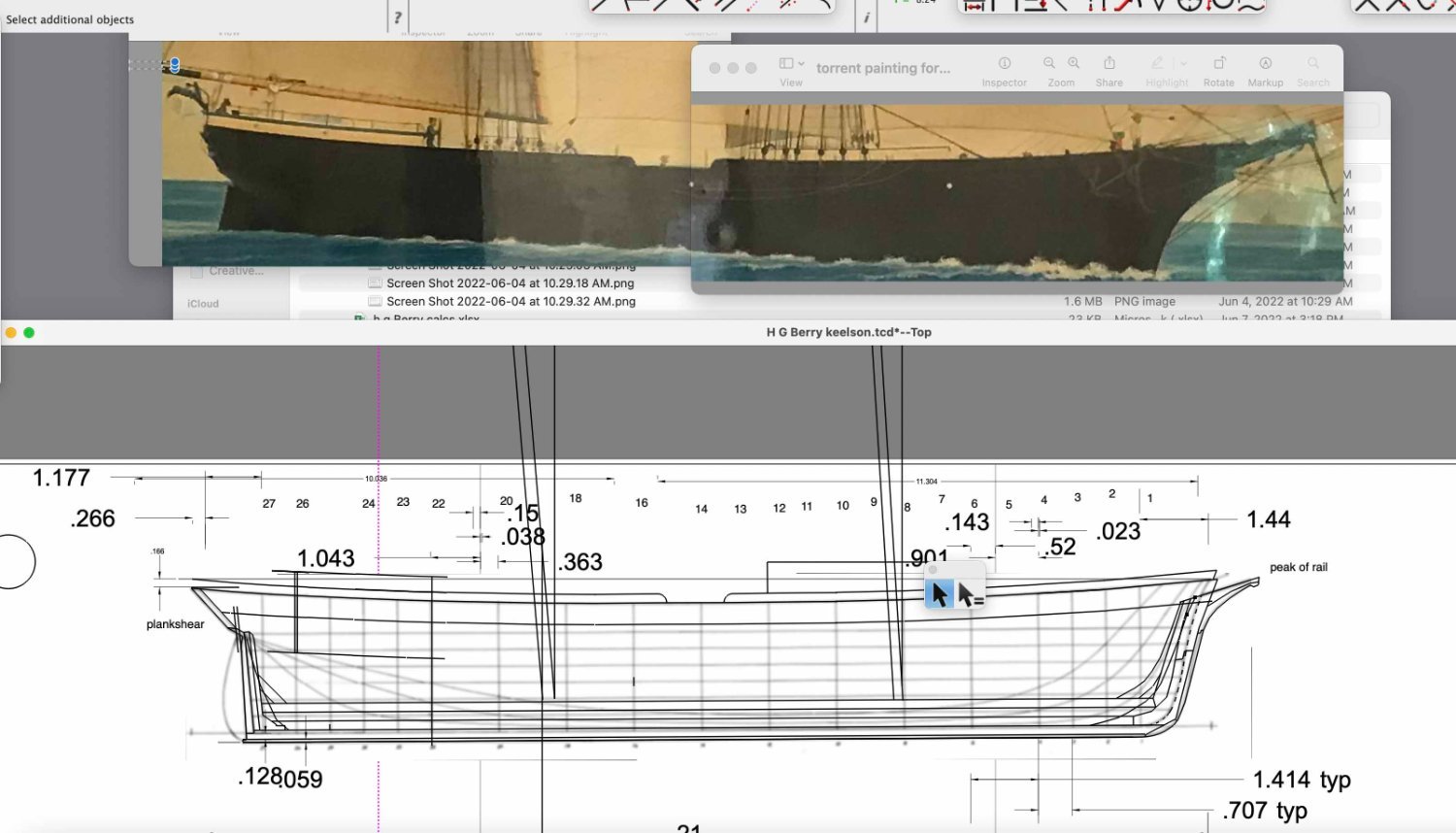
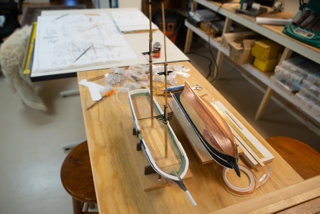
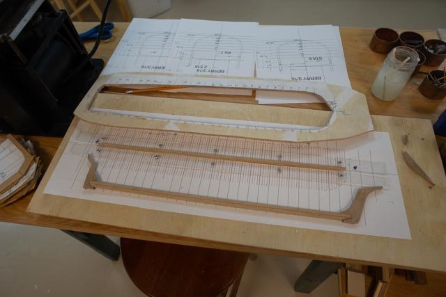
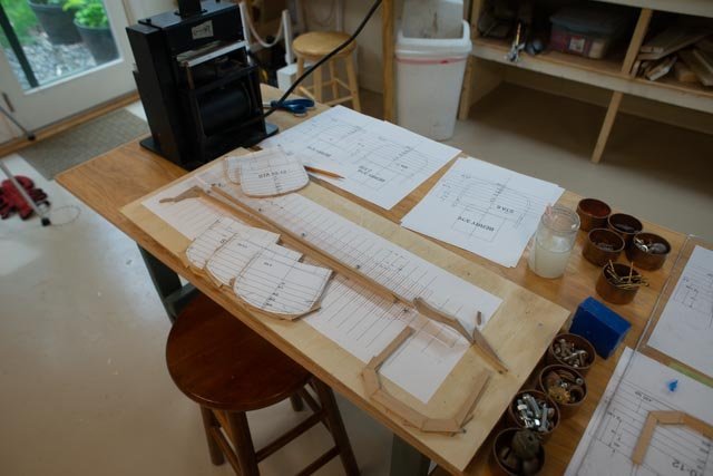
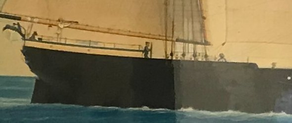
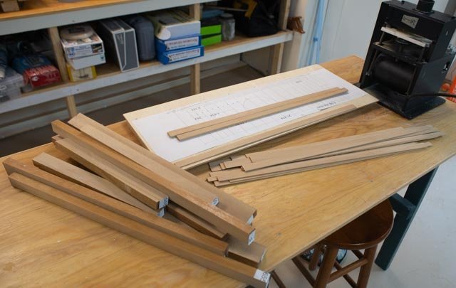
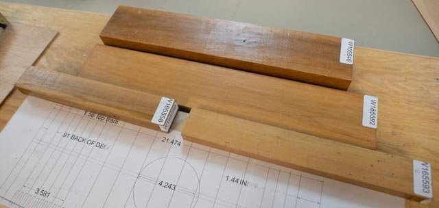
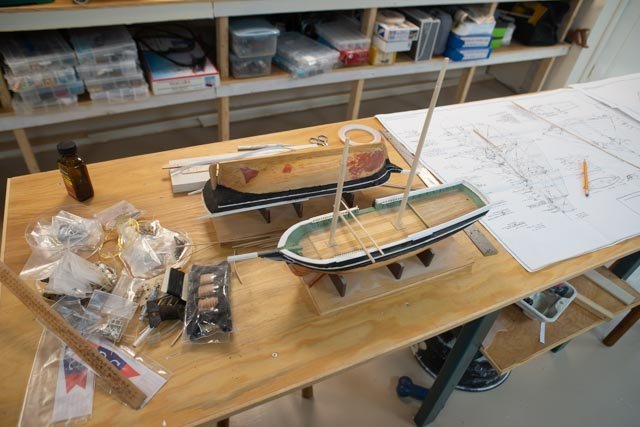
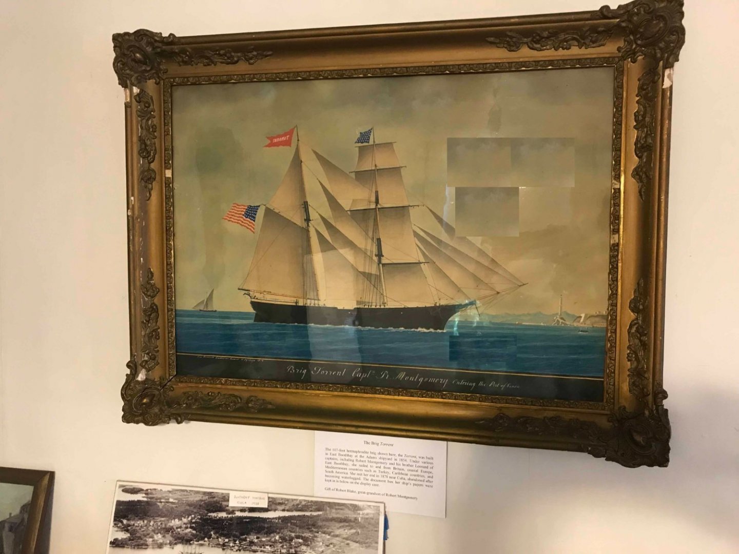
Post 4 Getting the side section figured out, buying some wood, and starting the small brig This episode has been fun. I am slowly learning the steps in migrating to the apple version of 2d Turbocad. Following my plan, I have used the painting of Torrent as a key element. Here are four views that I used in scaling things 11 The aft half of the hull to show placement of the cabin. See in this view that the wheel was brought forward of the cabin and mast placement. A very unusual element that was changed as per the record. I am not modeling the wheel there and will have a normal after deck and wheel as both vessels, Torrent reworked, and HG Berry were described. As I learned both the Berry and Torrent had the cabin clear across the deck, I will follow that idea. 12. The forward half of the hull for measuring the mast placement and getting the shearlines feeling right. I also used this to locate the crew cabin 13 A detail with a sailor of the fore deck helps in determining the height of the main and fancy rails 14 A detail with the helmsman. I also used this view or setting the height of the cabin roof and rails. 15 here is a working view where I did not embed, but just brought the photos onto the screen for comparisons. 16. here is my current draft of the side section. I think I can now get going on the main elements like the stem and keel assemblies The small brig Albert [ et al] In the following view I have taken advantage of having two hulls to retask from whalers. 17. the two hulls: the far one is our brig. I removed the former poorly installed copper and got ready to rework the hull. I am using the near one as a work platform to build up the masts and spars. This approach is nonlinear, as I can work a little on the spars, then work a little on the bottom, and then work a little on the new POF brig. The wood for POF I have read so much by the experts that better modeling comes from better wood. My last two builds were in Poplar and Maple. Easy to get and easy to work with. For this project I may have gotten ahead of myself, but I have splurged. 18 here are four pieces of Costello that I bought online. The dark color I found was a coat of wax. 19 First up was some initial cutting on the normal table saw to get all pieces under ¾ inch in one direction. I then used my model table saw to make up a supply of 3/32 by 5/8 and ¾ pieces to make frames [ based on 12-inch frames that I am still reviewing] and a few at 3/16 to make up the keel and stem assemblies. I have to say I understand all the accolades. This is beautiful wood. I hope I can do it justice. 20 here is an early progress shot on the spars. I include images of the Crothers books that are so invaluable. 21 here I have filled in the whale cutting whole in the former whaler. I also made up a template for setting the sailing brig in some water. Next up the keel and stem assemblies All for now


-
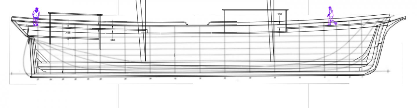
Post 3 Apple vs Dell and a retired amateur ship modeler I started on a slow slide down a slippery slope maybe 3 or 4 years back buying my first iPhone to replace my aging android phone. I about a year later I realized my android tablet was long in the tooth, so I went with a new iPad to link to the phone. Then an iWatch that answers if I cannot find my iPhone. Then last xmas, with my aging dell, to go all in with a new iMac. It all sounds easy right……It really is a major event. I have entered a whole new universe. I will not go far to explain all the effort of the transition. It is like moving to a new country and learning a new language and then realizing the difference in culture. More than that…truly. The part of the universe that is relevant to the build is the migration from an old turbo cad that I knew how to play with in 2d, to the cad systems available on iMac. VERY DIFFERENT! I had thought that this next build would be my entry to elementary 3d. The obvious example being the outer and inner curves of all those frames. My colleagues had convinced me to try Delphship and model the hull first and stations would come out just right……..so far as I can see nobody does that on iMac unless they have a masters in IT. The first thing they discuss is adding a second operation systems to my nice new machine to run programs….eeek no thanks. I gave up on finding Delphship or any of those systems talked about and raved about in this forum and similar google and YouTube searches. I finally bought the Turbocad for iMac thinking I would quickly migrate and then be ready to learn a little about 3d…….ugh….. everything is different. Anyway, that is my rationalizing for taking short cuts with no further apology. Please understand all below is limited to 2d drawing on new [ to me] software. Design basis for HG Berry Starting to build a vessel with no drawings is always a challenge. As stated above I first rationalized the basic design by getting lines for a similar aged, locally built vessel and moving on. That is only the start. Things to solve knowing I am only doing partial deck down….so by example the sail plan is not critical on this vessel other than major spars, bowsprit etc. the line drawings I got are very basic and only show what would have been available with a half model. So first up…….How is it framed? How are the stem and sternpost to be modeled? Fortunately, in an earlier build Aphrodite, an 1853 ship built in Boothbay, I got into the books by William Crothers. For this build, I will start with the American Built Packets and Freighters Of The 1850’s within which he includes a Brig Volonte : 1852 Wm H Webb in New York. She was 112 ft and 307 ton. That’s the same length and rating we are doing here. That means with some guesses I can use his details and move forward. 09 here is a first draft of a typical frame lay out. Frames….I am still thinking this through. Last time was my first time, and I struggled [ working 2d cad]. I chose to make every frame with an added 1/16 inch extra outside and inside for sanding once in place. Skilled modelers, many in this forum have mastered using 3d where the software calculated the right curve and bevel so one might simply connect the lines. That way one gets almost a perfect frame inside and out before installing it. That as of now is over my pay grade So as we start, I fully am aware of the challenge and managing expectations, the need for sanding. I am also nervous as I move from 1:48 to 1:64. 10 Here is the second draft of the keelson and frame layout. Mast locations and more thought at the bow and stern. next up the plankshear etc. The source used to draft of the keelsom assembly I showed last time came from the Crothers book. Working at this small scale, I will combine parallel pieces…the shoe, keel, one piece a space and then keelson, riser1, riser 2, one piece. . This is the kind of short cut I meant. I know the true modelers would make each piece and the bolt them etc. They make me humble Sailing plans. The fore mast. I have searched the net and many books for the smaller brig design. Chappell has few examples to use. First up is to guess if there were three each square sails on a shorter foremast in 1825. It seems clear in the 1840 images that a higher mast and four sails was the way of the world. Pavilion 1929 from my last study was converted to whaling in 1844 was always 4 sails on the foremast. As the three images of local brigs all show four and I am going in that direction. Location of the masts. I went to 17 examples on the web and measured on the screen to determine the position of the two masts. They were all different. I took an average just to see where it fell…not sure yet what a right answer might be. Reading Crother’s book on The Masting of American Merchant Sail in the 1850’s he wrote in one place there was lots of variance in this aspect to sail rigs. He then figured out a standard tied to Lloyds standards. He shared two different methods. One is based on placing the masts, so one is 10% aft and the other 34% fore of the midpoint of the waterline. That means the sum or more than 40 % of hull length between the spars. The second method is based on the ships overall length….used in the table in his book. The subject of the book is merchant sail and clearly the majority are three masted barks or ships. He did include a few brigs with partial information. The Volante masts were recorded to be 24% forward and 12% aft of the mid-point. It should be noted as well that Volante was a full rigged brig. I am not smart enough to say that re rigging a vessel from full to half brig would include restepping the mast. Common sense says no, they would have remained in place. That means the sum of 36 percent of the hull length separating them and a bit forward of center. So what to do HG Berry large brig…. When I take the painting of Torrent and measure, that does not match with Crothers projection. The mast separation is a little less and the masts are clearly centered. Maybe it was artistic license? Regardless as I am laying it out now the artists choice looks good to me and I feel it should be ok to use that as a basis. Small brig, former Kate Cory design…. Taking a look at the Kate Cory hull and sail plan drawn by the master Erik Ronnberg, we find the following. Using the waterline, we go back 8% and forward 30%. And using the full length, we go back 6% and forward 27%. That really is not far away from what Crothers was saying. So I think I am better to use the existing sail plan as prepared by Ronnberg and be happy…..it looks good on paper • Stick with the painting…it looks good • Stay with the kate cory rig as the difference are truly subtle. By staying I have a complete coordinated sail plan that I can plot out for making sails. Next up get some wood and start of smaller brig rework.

-
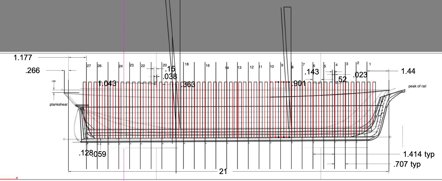
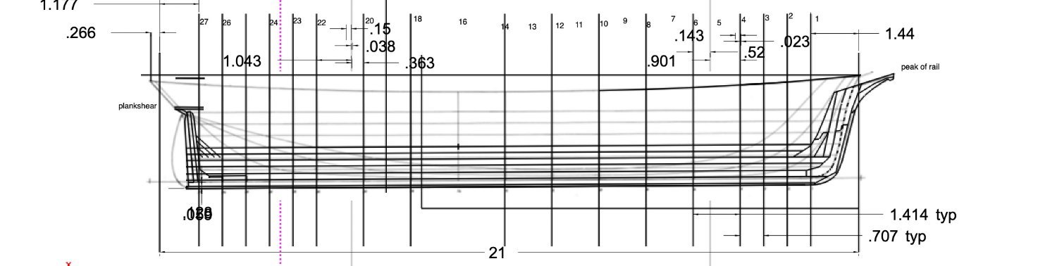
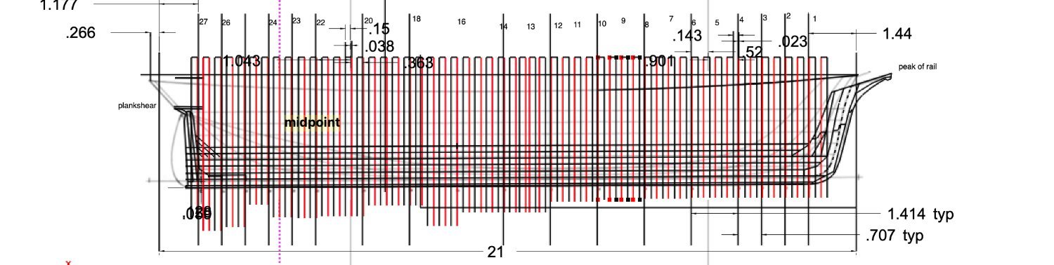
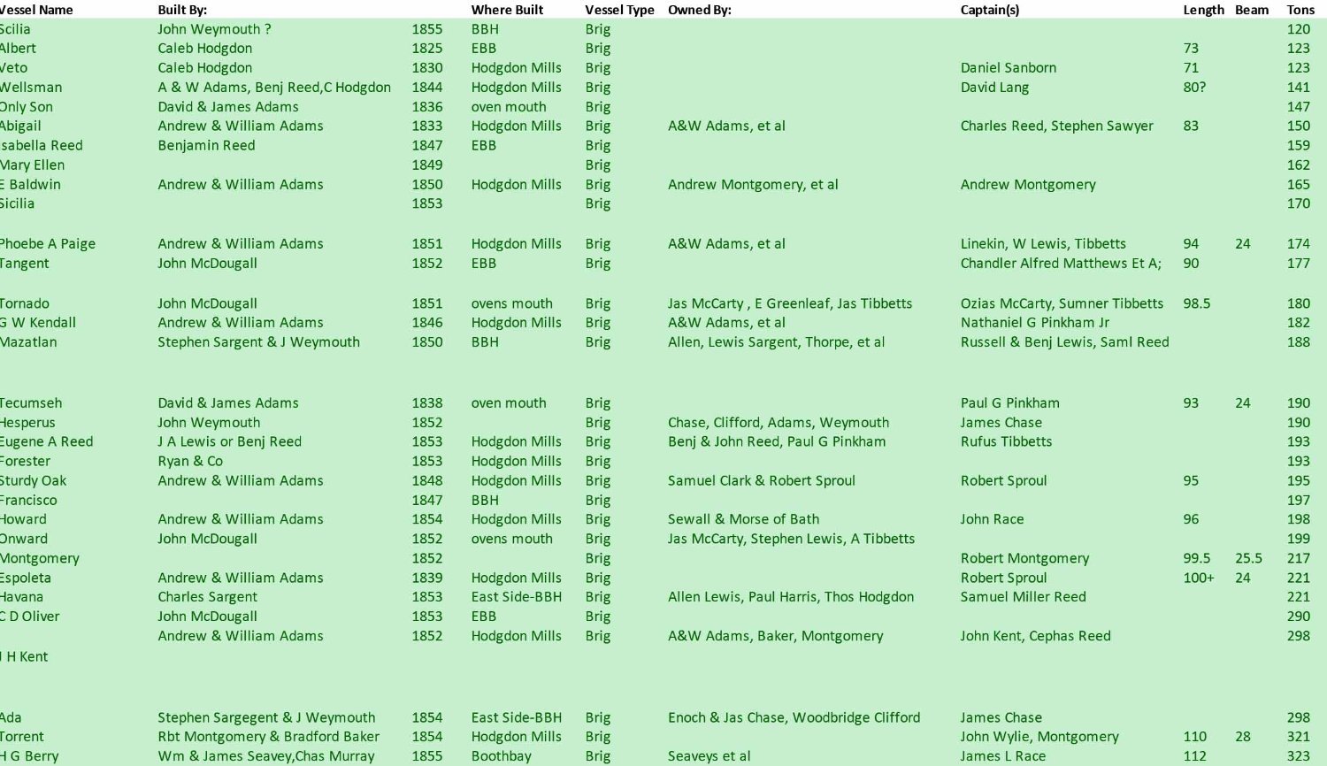
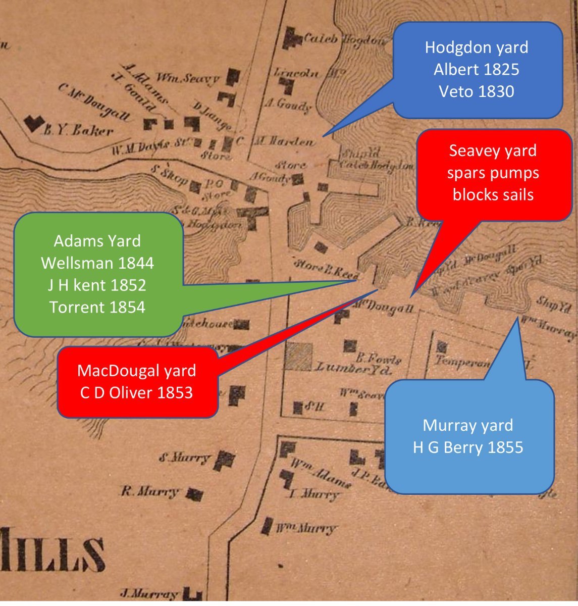
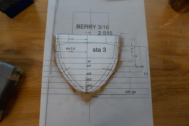
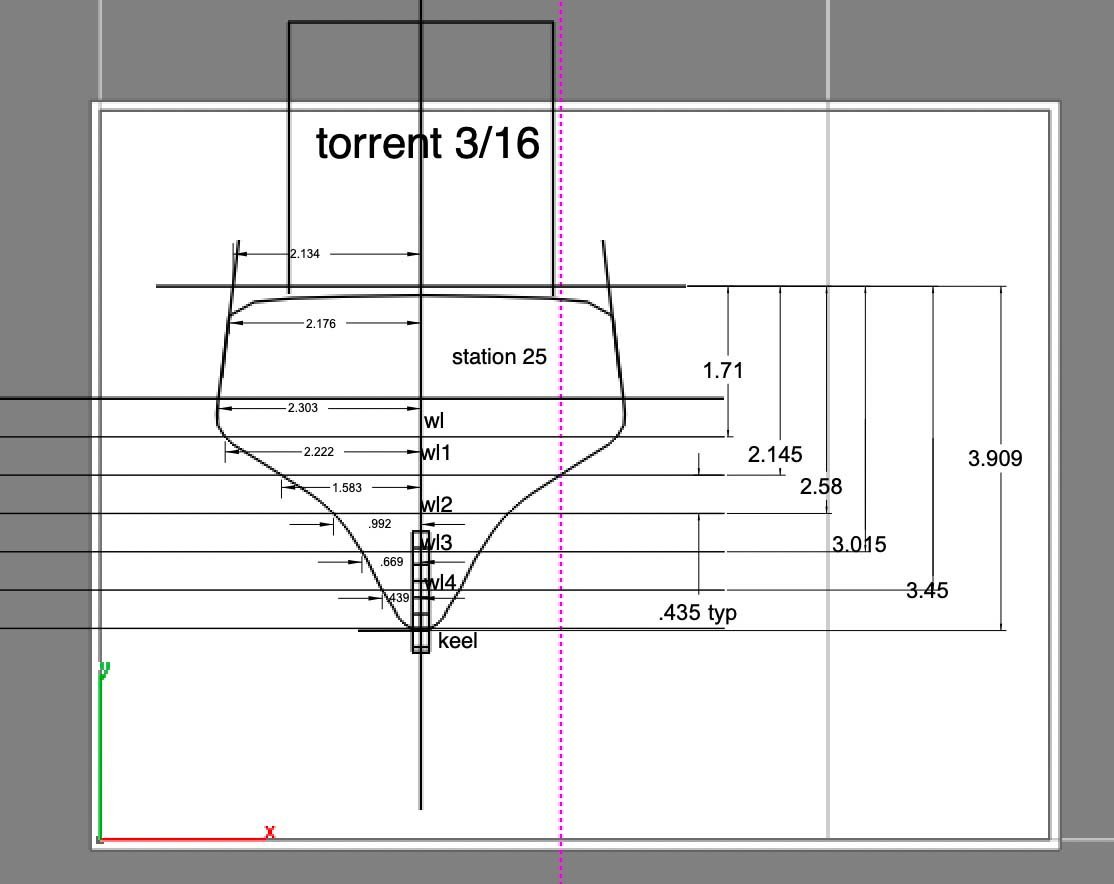
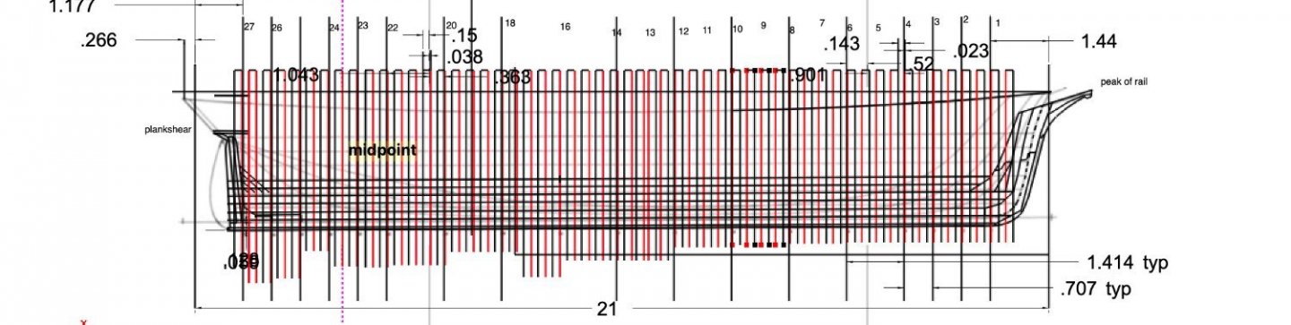
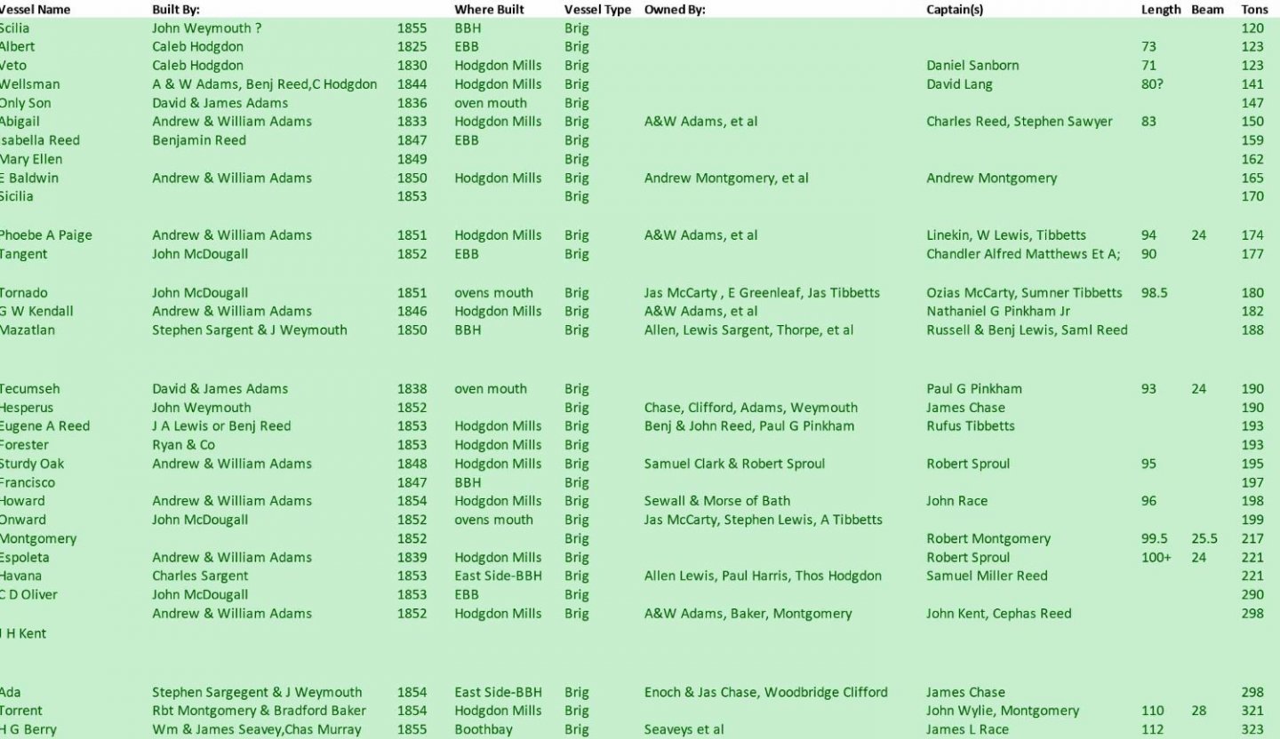
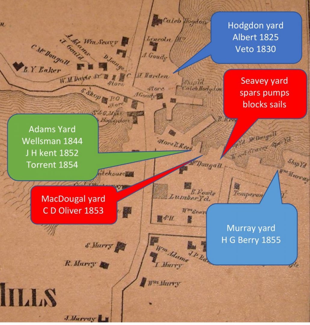
Post 2 Choosing the hull plan and settling in on the common location I have been studying the whole Boothbay region early shipyards over the winter and have taken on the editing and updating of the current vessel database. I will be giving a talk on the subject in August. The following sorted table is the current listing of the 32 Brigs built here in the region between 1825 and 1855. 2. here is the full list sorted by size. 3 here is the list of the 5 larger Brigs. They were built in 1852 to 1855, which is clearly the end of the era and set the date for this log. The last one launched was H G Berry. I have done some searching and went, as I have before, to the Main Maritime Museum vessel plans and selected a brig built in Harpswell, Maine just 30 miles away. The plans advertise the half brig Mary Hamilton, built by Curtis & Estes, Harpswell, 1853. Length 119’. One sheet of lines. Drawn by George Parker. Reconstructed from builder’s half model. H G Berry 112 feet. 4 here is the list of the 5 small ones. They are 75 to 80 feet long and 120 to 147 listed tons. They were built 1825, 30,36 ,44, and 55, which also covers the whole period. As described in the first posting, my plan is to take that mostly built hull and retask it. The two paintings of Boothbay built brigs do help confirm the sail plan. There are no other surviving documents to copy, I am following the assumption that there’s little variance in the general shape of the rig between these times. I suspect the materials of the rigging would have been different over thirty years and I will try to look at that subject as we advance. Before we get too far in, I need to figure out where this representative “ways “are to be located. 4 of the 5 larger brigs and 3 of five of the smaller brigs were built in East Boothbay. Also, some of the owners were there as well. I assume that I will be using storyboards as part of the display and not be trying to build a huge diorama. H G Berry was built in the Charles Murray yard close to the wharf where a working vessel would have come. See the map for more info. 5. here is an 1857 map of East Boothbay. I have annotated the main yards. The receiving dock for daily shipments from Portland is just north of the Murray yard on that point of land. This view shows where 7 of 10 of our smallest and largest brigs were built. Just for the record, 12 other brigs [ call them mid-sized] were built in this small village in the same period. Thus at 19 of 32 it is still the main location. I will give a short summary of the yards in a separate update. Let’s get started on the drawings for H G Berry This for me will be a multi-step process. I am truly finding my way. I first embedded a scan of the length section into cad and scaled it. I will use it to develop the frame spacing, Keelson assembly and building board layout. I have also taken the cross section and used it to draw first the stations as if I am building just bulkheads and then slowly adding mid frames. 6. here is the length section in, and the full frames roughed out. This first attempt in the new software simply takes the stations from the drawn plan, scales it and then divides the stations. If I were going to cover up the frames I could simply move forward. 7 here is my first draft of the keel keelson, risers, stem, and sternpost assembly drawing. More work to do here. Much more to do here. 8. here is the first draft of the building board layout. This will come last after I decide on the right spacing of the frames. Again much to do next up more reading, practice with new apple software and sail plans


-
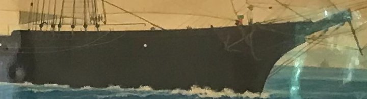
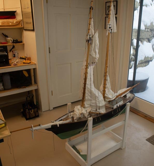
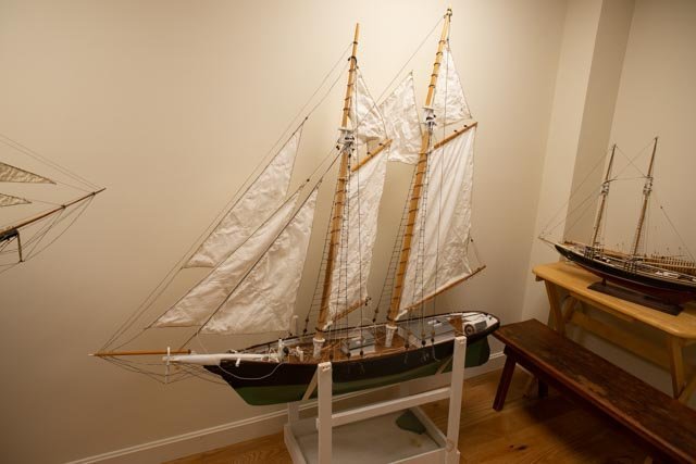
Post 1 The Beginning I start this log before starting the actual build as I am completing to gather the research involved after having selected a subject. This build will include more Boothbay Built vessels, and I chose to study our brigs. I began some time ago with the following image from our local Boothbay Region Historical Society of the Torrent. She was one of the last brigs built in 1855 and will surely be part of the story. 1. This painting was made in Genoa, Italy I believe in 1856. Apparently, a result of a practice of the time, where an aspiring artist would sketch, then quickly paint and sell an image to the visiting captain. I am naming the project Brigs of Boothbay. The first recorded Brig in 1825, was Albert and the last recorded in 1855 was the HG Berry. I will represent both within this log, but the real build will be the newer and large vessel of 1855. I will build that vessel. H G Berry as a POF build partially completed on the ways. But first to explain the plan: I turned to the wonderful book, the Shipping Days of old Boothbay by George W. Rice. There and within a few other sources, we have found recordings for 32 brigs built here between 1825 and 1855. I will include that list in a table later. I characterize the list as follows. The early brigs included at least one full rigged version, but soon most became half rigged. The hermaphrodite brig [ I am told here in Maine is a half brig] was apparently preferred on the coast associated with Maine sailing. It seems that much of service was to and from the West Indies, however the practical need to sail up wind remained the deciding factor. To sail from New England to New York and beyond means up wind all the way! They often took lumber, dried, or salted fish south and brought molasses and trade goods back. Reading further though the book, Mr. Rice tells of many worldly voyages to the Caribbean, the Mediterranean and further in these sturdy vessels. The earliest Boothbay brigs were roughly 75 feet and just over 120 tons. After 1850 they passed 200 tons and by the end of their run in 1855, they, including Torrent and H G Berry, were 110+ feet and roughly 320 tons. There are five of each large and small, and that is what I plan to show……bookends one might say. Large Boothbay brig; Plank on Frame. H G Berry 112 ft 320 tons. .....I believe after taking time to make frames they are a feature of the build. The easy way to make that part of the show is to have the vessel partially planked and decked, so one can see inside. Then I also like to show a vessel sailing. My solution this time will be to have two vessels. Small Boothbay brig; POB partially completed kit hull. Albert 75 ft 120 tons......Retasking of an old build. I started the kit for Kate Cory years back. I had two hulls and at the time thought to build two whalers. I will continue the log of that build using one of the partially built hulls completed as a period schooner after this build. The second hull was to be an 1829 Massachusetts brig Pavilion. I will use it for the small brig I reference here. The completion of that model will represent all the rigging and sails that obviously cannot be shown with a vessel under construction on the ways. She will be called Albert, the first brig built in 1825 but will represent all the 5 smaller versions. They were built 1825 to 55. She was 120-ton version brig and will be shown under light sails [ most furled]. Thus, I can complete a full build [ sort of]. And I can at least practice all the tasks. Furling silkspan will be a new one to me. My last two builds, if combined, were like this one. One was plank on frame on the ways and the most recent POB sailing. They were done at a comfortable 1:48 scale. As I look around at my partially completed projects and consider the practicality of sharing displays, I have decided to try this build a bit smaller at 1:64. The brig H G Berry I plan to build as the feature of this project is one of the last four Brigs locally built. For the image I will use Torrent shown above. As partially built, that will be limited to the hull. Four of the five large Brigs were built in East Boothbay, so I will select East Boothbay as the site. Torrent and H G Berry were built less than 150 feet from each other less than a year apart. I must assume with so many people working amongst the yards in this small village, that very few variations existed. I will explain that more in an update about the local shipyards. There was an interesting twist to the original design of Torrent to record but not build, and that was altered some 15 years after. The captain’s cabin like a few other brigs of the time, crossed the entire deck. Most would have maintained deck level passage outside the cabin. This cross-deck configuration forced the crew to climb on the roof deck to tend sails and to gain access the wheel, located aft of the cabin. To avoid all this interruption, the original build moved the wheel forward of the cabin and used chains from the wheel art to the rudder post. The full after deck area, normally for the wheel ,was incorporated into the captain’s cabin. The noise of the chains was apparently unpleasant to the captain’s companion. The owner cut off the aft section of the huge cabin and replaced a normal wheel and exposed deck aft of the cabin. That revision was a more normal configuration that I have read was shared on H G Berry. next up getting plans all for now .
-
June 2022 I have finally figured out what to do with this build and can now get back to work. First, some rationalizing. Brig build. this version to continue in another log 1. Kate Cory was built originally as a Schooner rig in 1856. She was then converted in 1868 to a brig. That means building either should be fine. Plans for both sailing plans are included with the kit. 2. Kate Cory was also rigged as a half Brig…. squares on the foremast only and this form is the local norm. 3. She was 75.5 feet long with a 22ft beam. She was registered at 122 tons 4. The five smaller brigs built in Boothbay were 75 to 80 feet long and 120 to 147 listed tons. They were built 1825, 30,36 ,44, and 55, which covers the whole period. My new plan is to take the partially built hull of Pavilion in this log and retask it. She will then try to be representative of any of these 5 small brigs under sail. [ see below that will not continue in this log] Schooner build. This version will remain in this log 5. I will take the second hull[ originally Kate] and complete it as a schooner. In 1827 and 29 two 76-foot schooners were built in East Boothbay. I may name the model after one of those, Katherine or Elizabeth or similarly list roughly five schooners of similar time and size as I am doing with the small brigs. 6. I have gone through a few of Howard Chapelle books and find multiple samples where the hull shapes line up ok. In the fishing schooner book however, they are most often in the 65-foot range. I have read in local maritime history that the fishing schooners were typically in the 50-60 ft range and the merchant schooners were similar, just roughly in the 70+-foot range. I read that in 1840 there were 9 listed schooners running freight on the coast and 30 fishing out of the town of Boothbay. This would explain the fleet so to speak. As I now can move forward, I am doing a parallel scratch build of the larger sized brig. As of now I will build showing her frames and partial deck and plank. A link to that build will be resting my signature once it is up and running. I will remove the completion of the Brig version from this log and move it to a new log to be started with the scratch build larger Brig. Those models are intended to be displayed together to tell the story of the local brigs. The final shift is that I have another larger fishing schooner [ built years ago as the kit Benjamin Latham and in need of repairs] that I plan to retask as a later built Boothbay fishing schooner, also of the same harbor….Photos that I have make a comfortable shift from the 1903 classic Essex built Benjamin Lathan to a similar 84 feet 72 to vessel. There are over 20 examples to choose from. The Sadie Numan was built in 1902, so she is my leading candidate. This effort is immaterial to the purpose of this original titled build. This addition will only contain images of the planned repairs and a few updates. The models will be displayed together, with a Pinky, to show the evolution of local offshore Boothbay region fishing schooners. This work will follow the Brigs. As the work gets going, I will record some of the documents that I have used to rationalize these moves. All for now
-
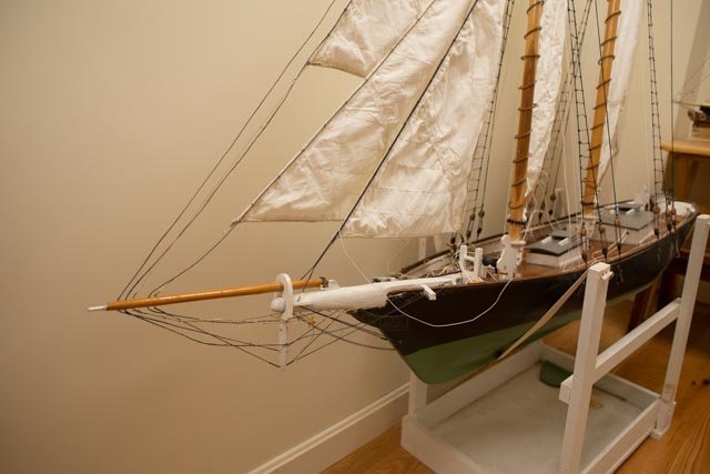
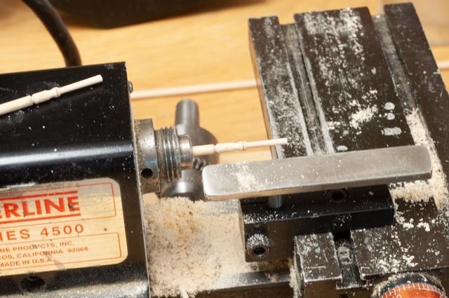
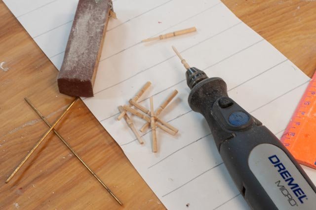
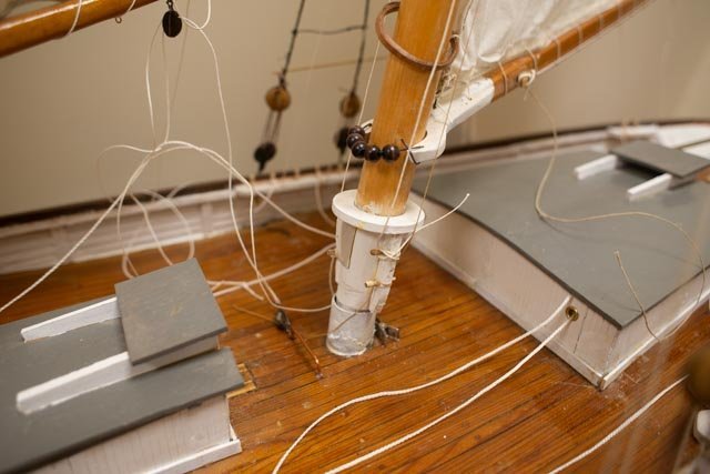
Post 9 Get the big old version fixed up and back on display or take her to the attic Last winter, in January, I thought I had plenty of time before now to both complete the 3/16 in to ft scale version and the ¾ in to ft scale version. Well too many other things were going, so to avoid taking the big one to the attic, I got it sort of done and back in the gallery. I then set the small one back up on the shelf. One of my diversions is the research I am doing to give a lecture this summer on the shipyards of Boothbay. With all that study now done, it is hard to focus on Massachusetts vessels….ha ha Any way with a few photos below I show the updated status “ to look at” rigging is done and she is resting comfortably. The “to make it sail” rigging was started but truthfully is laying on the deck for another day. This build may indeed set a record for duration Here below we see the spring effort 214 the starting point to just stand up the masts. 215. all rigged and set in new resting place. 216 a look at the bow rigging . 217 turning new belaying pins. 218 tapering belaying pins for setting 219. Rail with new pins and line tied off. Here I started to make coils, but then thought…if this is a RC sailable model, are the working lines to be working or made fast and coiled etc. all for another time 220. here she sits in front of old Charles Norton. My recent schooner Ada Cliff just went downtown for the summer, so the gallery is a bit thin I am off to a new build so this one must rest again Cheers
- 23 replies
-
- 5
-

-
- dancing feather
- pilot schooner
- (and 1 more)