-
Posts
856 -
Joined
-
Last visited
Content Type
Profiles
Forums
Gallery
Events
Everything posted by Jond
-
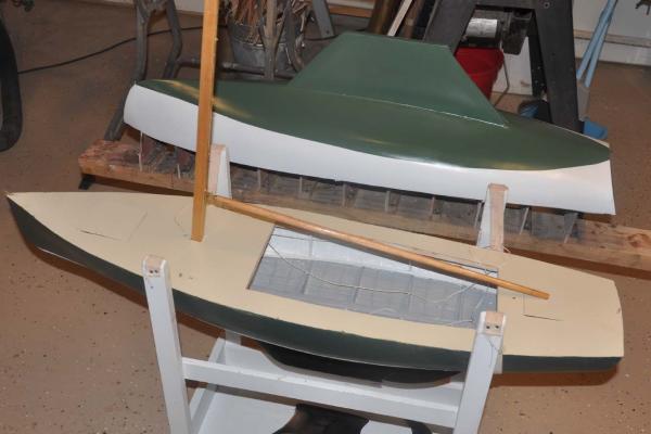
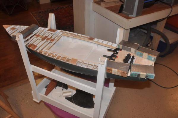
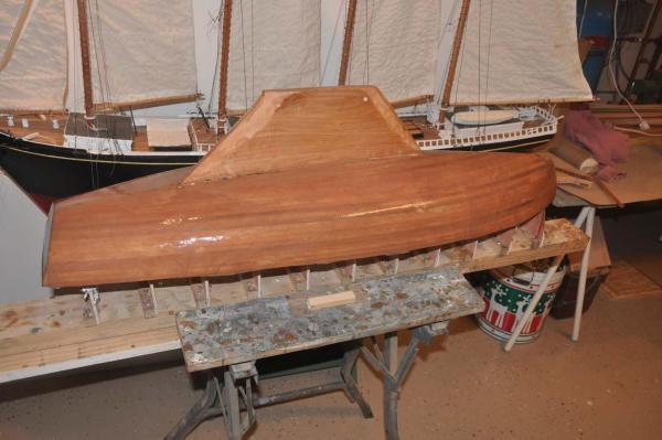
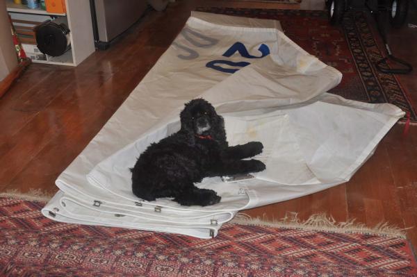
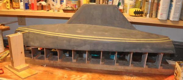
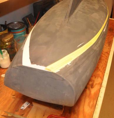
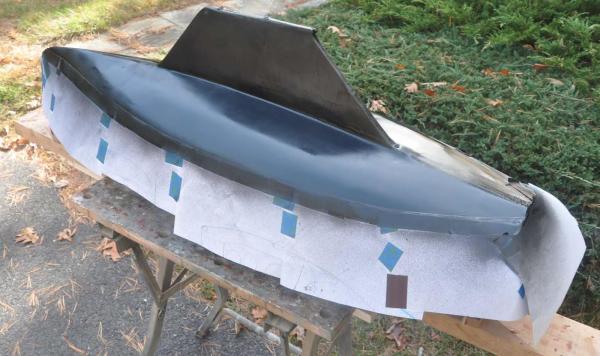
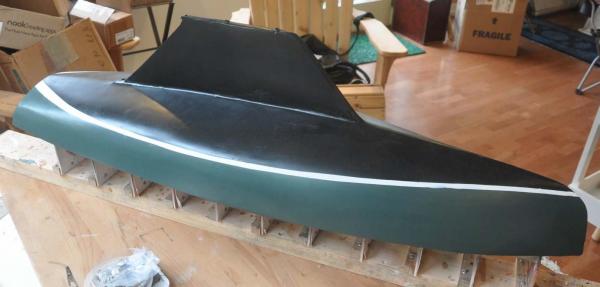
Thank you everyone for your following along. I will do a longer post after the holidays but just wanted to share status as we take a holiday break. We have had very nice fall weather here in Maine, so I was able to rush a bit to allow me to spray paint the bottom on hull 2 outside. Once it is too cold for outside spray, I am reduced to normal paints. I just like that first construction coat or two to be good old rattle can enamel. So I spray and carry her inside to harden up. Then out again for coat and back in side to dry. I got the second hull ready and painted. Please note she is not yet named. I chose the paint scheme of my boat bittersweet prior to the re-skinning. Her photo pre-skinning is early in this log. I also plan to upgrade this hull with a mahogany transom. The masts and booms are also done, so I set one in for the photo. I am working on the spreaders and other details that I shall pick up in January. That all needs to be completed off the boat. I also have received the first sail. now let's all enjoy the holidays cheers
-
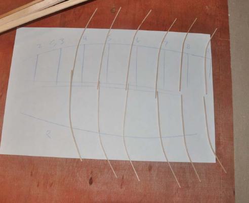
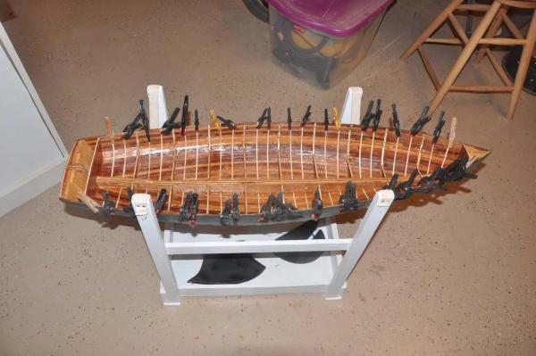
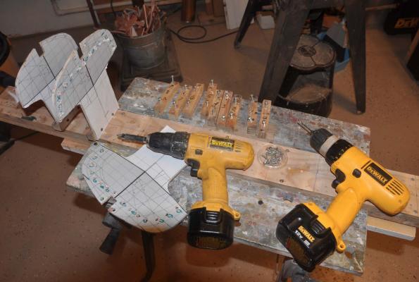
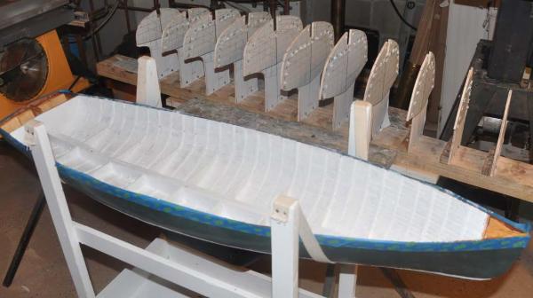
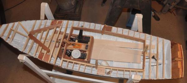
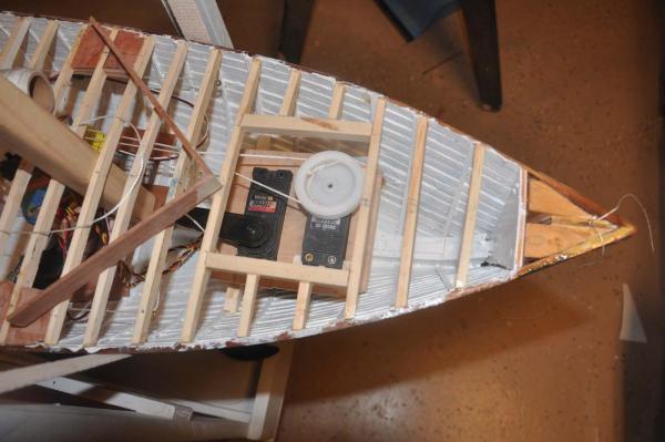
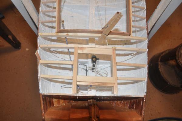
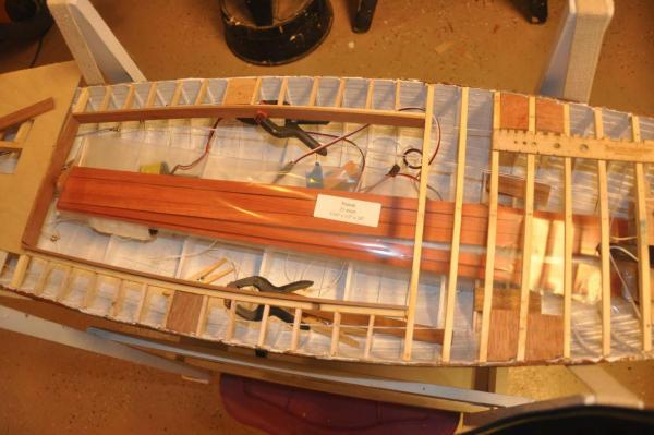
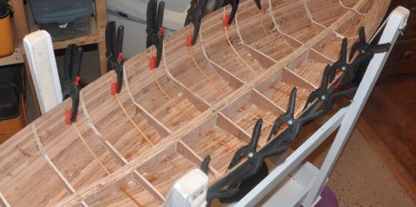
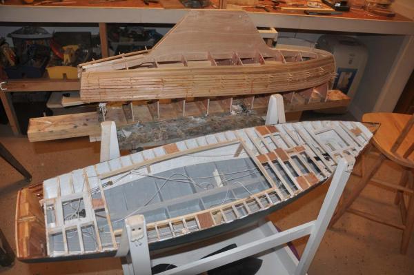
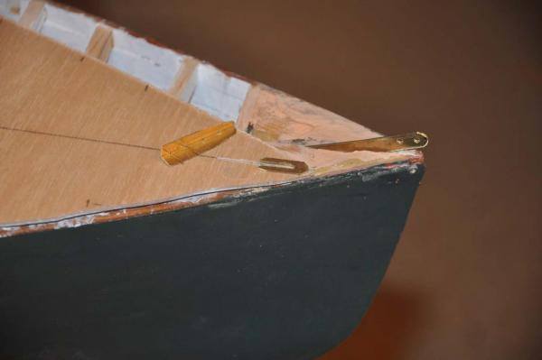
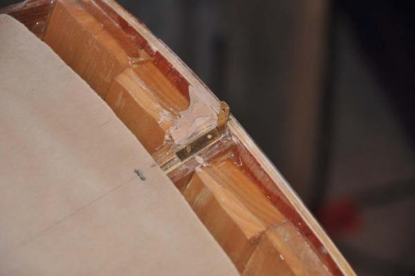
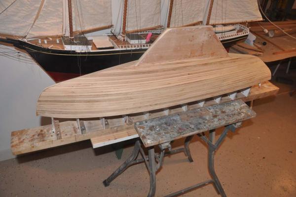
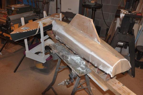
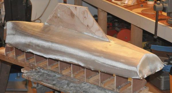
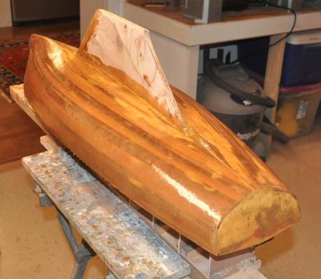
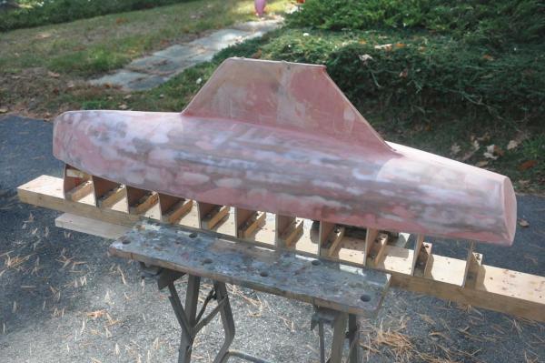
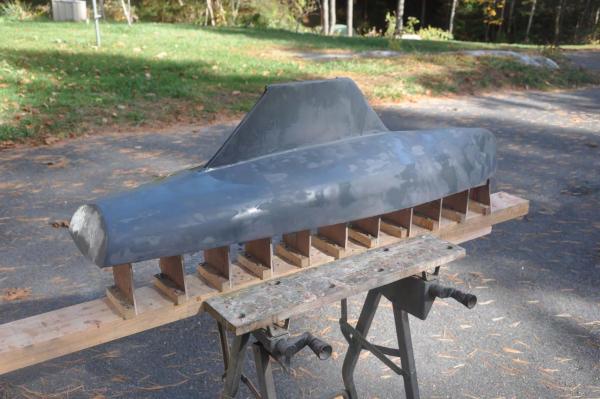
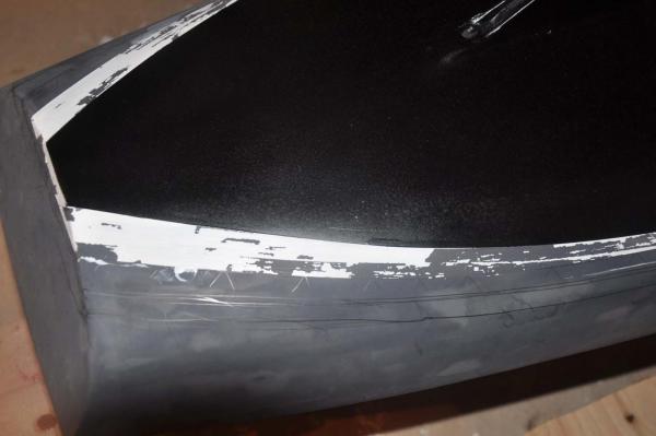
Hi all I thought I needed to update the log as progress is being made despite many interruptions. Progress is moving on three parallel fronts.... hull 1, procurement and preparation of spars, sails etc and hull 2. I am working on all three so please excuse some confusion as I go back and forth. We must remember this build is meant to include two boats, so they can race. Ok last time I left out a step or two on hull one interior. 1. After cleaning up the interior I needed to install ribs. To get the best look I chose to use 1/16" bass because with ammonia water it was easy to bend and shape. In scale it should have been 3/32". So to get the right look, I chose to mount them proud onto the coat of sealing resin. This method gives more of a shadow and makes it work. A problem to resolve is the building method included placing a 1/32 strip of birch plywood on each form. These sub ribs were separated by tape so they would easily come off the form and remain in the boat. They are at each 3rd rib line. 2. There are two problems or lessens to consider in hull 2. a. Oops the boat is 1/16th too wide because I did not take consider the 1/32 sub ribs. b. The sub ribs are located every 3rd rib and are 3/16" , just wider than I wanted for the ribs. I ripped some 1/32 strips later to compromise and they came out OK. see painted photo. here the wet ribs are set at one third points betweeen the formed ribs and left to dry. here the ribs are marked and stored until the inside is coated in resin here I have coated the inside with resin to seal the boat . i laid the ribs on the resin to accentuate the shadow line. 3. My first attempt to place the servos was to consider a removable cigar box approach. I assembled the items and then set in the box. It did not take long to decide that was not the way. all RC equipment to be set and secured when sailing then removed. I chose not to pursue this option at this time. 4. The only place that gets wet when sailing a pond yacht is typically the fore deck. Thus one does not penetrate that deck ....after a lot of thought I decided to break that rule and make a full forward hatch so I could bury the servos and stuff. here is the new foredeck hatch for access to servos. 5. The rudder also needs access, so a smaller aft deck hatch is made. here is the aft deck hatch for access to the rudder. 6. Several folks at the NRG conference recommended to me that I should use Paduak to replicate teak. I bought it and yes it is beautiful. Here it is resting in the boat. I will think more about this as my boat is really teak and I have that material. This issue is not solved yet. 7. I was up seeing my real boat and found that we are using special hard bilge paint which is gray. Even though most is below the teak sole, I chose to paint it as it should be. The 3 center sole boards should be removable for bailing and I need to do that too. It will be nice when the right color is there to greet us. here you can see the common progress. As I was painting out the bilge in hull 1 and I was starting hull 2 8. Completing all the hardware blocking under the deck and building the six chain plates is the final activity before adding the deck. 9. For the back stay I chose to put a simple L bracket on top of the keelson and screw and epoxy it in. 10. For the head stay I need a stem strap. After a lot of thought,I chose to cantilever a brass bar. It will be in a bed of epoxy and have the deck plywood holding it down. I then glue down shaped brass flanges on the deck and pin a brass angle on the bow completing the fitting . I will show it against the real thing when it is all installed and cleaned up. some day I will learn to make a jig and silver solder a strong fitting. lets see how this looks though. 11. The shrouds plates were really hard for this boat. The normal design is a single shroud bolted to the floor. The option is to have the turnbuckle below deck and only the shroud penetrating the deck or to install a twisted bronze chain plate, bolted to a link through the deck and have the turnbuckle above the deck. In the 1970's the new boats have aluminum masts and a double shrouds. The approved class design allows upgrading the wooden boats to include this added shroud. Its purpose I will show in a later post. For now I am replicating my real boat. we are simultaneously upgrading it by adding this second shroud to stiffen the lower mast. In my boat there is a OAK plank securing the floors before and aft of the shroud to average out the uplift. There will be two twisted bronze bars with links and that is what I am doing. A big lesson learned.....I learned that I need to sort all that out next time before I build the deck frame . That way I can get my fingers in there and make the actual bolted connection etc. I needed to use a copper wire and that I bent to hold it down. Fortunately it will not be visible. 12. The after deck is now glued down with epoxy to the deck frame. here I and securing the after deck.. Hull 2 starts 13. Hull 2 can start now we have the building board. Reusing the marked, labeled station blocks , screw holes etc. meant I could install all the forms in minutes......nice re 13 a here as the forms are all set we can see the painted ribs on hull one. note the issue of the bent fomes in the last post. I needed to add double braces to fix it. 14. Here we are with all the planking in place and rough sanded. She is resting next to CHARLES NOTMAN, the downeast schooner I built last winter. 15. Here she is next to her sister getting her 6oz glass fiber blanket 16. Here we are with two coats of resin.
-
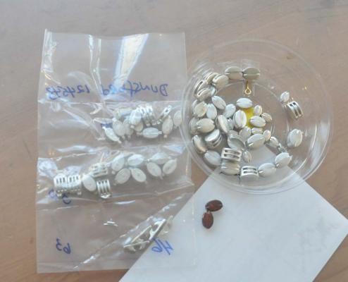
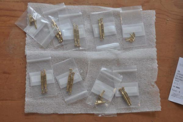
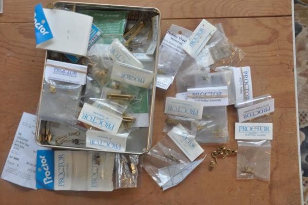
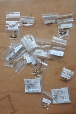
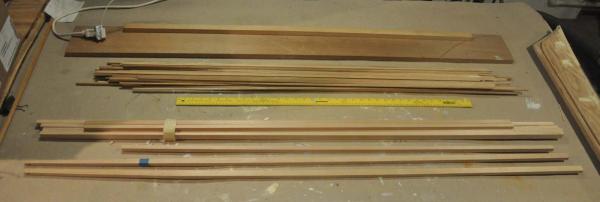
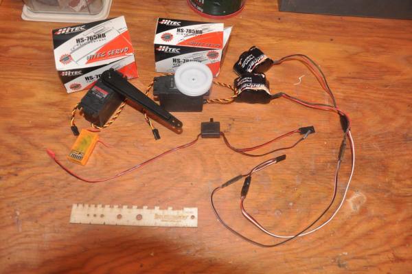
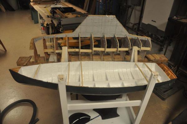
Hi all I wanted to update as we are heading into more holiday breaks. In general I am proceeding to figure out how to build the first hull and simultaneously start the second hull. This is a procurement stage. I have been successful working with a local builder of BHOD's to copy drawings produced as recently as 2006 for building a new BHOD in Maine. These drawings add many details that will be important. also I am field measuring as one of these first 2 hulls is indeed intended to replicate my real boat. I will identify a few examples as I get the assembly of the items as there are variations. So what do we buy and what do we make? 1. Masts and booms....I bought Sitka spruce blanks. It is accurate for the class and wonderful to work with. I have used it on my previous boats too. 2. Planking: we are back to ripping down clear cedar to 5/32" by 5/16". A little more care and the results are a little better. Practice is important. It is still too much load fo r the mini table saw and I need to consider that aspect too. here I have shaped two of the masts and inserted the brass main halyard sheaves. I have also stockpiled the planking for hull 2 3. Mahogany...I am buying Mahogany for work on my real boat and am using some scraps from that. I also found some 1/8" craft wood strips that is perfect for cockpit combings, cleat plates, splash board, mast step etc.. 4. Teak is an upgrade option included in many if the newer boats. My real boat sole is needing replacement, so I am upgrading it and thus this model needs teak. Several people have told me not to try to cut down teak. I may anyway as I have scrap to play with . In the mean time, I found Jason Clark for Crown Timberyard and he recommended and is providing so Paduak for the sole flooring. Hardware for traditional design these boats are alternately rigged with traditional bronze of the newest high end Harken fittings. there two hulls will be traditional. 5. Gooseneck and Turnbuckles: they need to work, so I went to a real pro Roger Cousineau. The fact he was a Mainer before relocating to Florida is just that much better. He remembers the BHOD class well and was helpful getting sizing right. I will need to add wings to his goose neck and will discuss when I do it. 6. Cleats and chocks. I am trying to stay in brass so that I can then treat all to get that 40 year old bronze look. Al from Ships N things sold me several sizes of the Wet Goose brand and they really look great...but shinny. 7. Winches and CAM cleats.....for the traditional look, I am still working on it...see mock up winch earlier post. this will expand to include Cam cleats for main sheet and halyards. little gears I guess 8. Sheaves. We have two: one main halyard and one mainsail out-haul. They are proctor airplane sheaves. 9. Blocks: here we have two sets. a. For the running rigging I have a combination of the fair-leads and a smaller proctor ' airplane pulley" . The idea is they will mostly be under deck and be actually sailing the boat. b. For the visual lines like halyards, jib sheets etc I have a combination of Bluejacket blocks that I shall paint and wash for affect. They are replicating the shell blocks of classic design. here i have Britannia metal to deal with. I will be painting brown and then washing green to get the look ....I hope 10. Stem Strap...this is a critical piece as it takes the load of the fore stay that is doubling its duty as a jack stay for the jib. My first plan to be sure we get sailing is to use a strong eye for the stay and smaller eye for the jib clew and then the strap is more for show. Ultimately I need to learn to solder a strong combined double eye and bent channel to complete the assembly 11. Sails...I have made my sails for the old schooners and small scale using muslin. One option for the 1938 sails was egyptian coton but they quickly went to Dacron. Modern sails are all Dacron with a higher tech revised class design, and that is truly the norm. This time I am trying to have race boats that look good and also perform. Rod Carr makes great racing sails for many classes in the AMYA and was gracious to bend a few norms to make sails for us in scale. here my second mate is helping me as I draw up and then scale down the sails for the sail maker. I will have a whole post on this issue as there is much trial and error going on. 12. Servo's and controls. I am no expert, but following the lead of others as well as a little success with my other sailing, I focus on using Hitec sailing servo with 3.5 turning drum on the sails and 90 degree swing for the rudder. I like to use two batteries harnessed, to allow weight balance and removability for recharging. There are many options foe receivers and radio equipment. 13. ballast...this will be a long story for future posts 14. tracks and carrs etc. like bales and other misc i will make most of this from brass stock and rings progress here was a fun day. I have removed hull one from the molds, added the ribs cleaned it up and painted out in white. I simultaneously progressed resetting the molds on the building board for hull two. Interesting issue. I bought 24 x 48 sheets of Luan, birch and fir plywood for these builds. I formed up hull one right after bringing the supply home. Sitting around for a month or so there was a slight bow in the luan that did not come out as I reduced size by cutting the individual molds. To fix this I had to add two more rows of braces to square up the molds.
-
Michael thanks...FYI I lived in Edmonton for a year and truly loved it. I am still an Eskimos fan Mike thanks.. I visited Switzerland a few times and wow...it was gorgeous too. I am learning too as I quietly review both your building logs. this big scale is daunting as the fittings need to look good but also in some cases work. cheers I am off for a bit
-
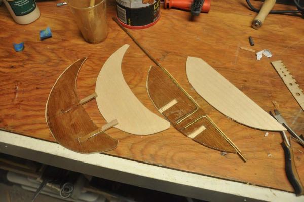
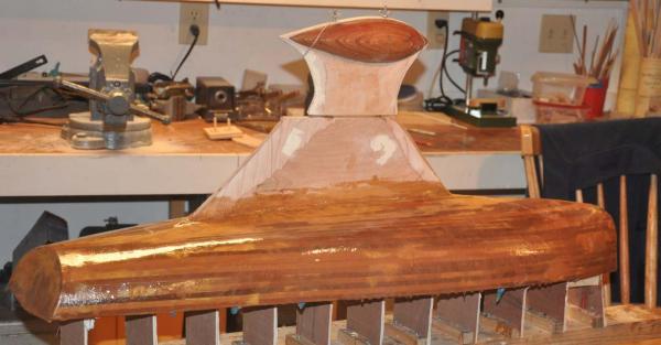
Milestone..ready to remove from the building board and mold! During the past few weeks we have been starting fall clean up, attending the NRG conference in Mystic, and trying to get progress on hull one before travelling. I just made it...sort of any way. Here is the process I followed to get a rough sanded cedar hull smoothed up, fiber glassed and painted. During this time we need to design and install the running sailing rudder and keel systems as well. Here I have laid out the proposed display and sailing rudder as well as the sailing keel. I am not following a design but on this proto type making the first stab using former experience and a few principles. the rudder. the sailing attachment will use wood peg inserts into the display rudder, so unlike the Notman schooner,[ my first attempt] there are not two brass rods permanently projecting aft. During the building of this proto type, I feel the use of cedar for the ' pegs' was wrong and the next one will be hardwood for strength. the keel. first I have to calculate the center of buoyancy and mark it. it was 7/8 inched behind station 5. second I needed to understand the center of gravity for the intended keel weight. I knew from a marblehead design bulb that the CG of the carved wood mold in the photo and lined it up under the CB. The weight. This hull only displaces 8-9 # of water. That almost cancels out with the full weight of the boat I suspect to be about 5-6#.....we'll see. A marble head displaces a few more pounds. The issue for me is overturning not matching the waterline. So here is guess work that will sort out next summer with sailing and most probably adjustments. I have a classic pond yacht which has 10# lead for 50 inch length and 800 SQ IN sail area. The depth is about 11 inches down. My Marblehead pond yacht had 10# about 15 inches down and also 800 SQ IN sails, This boat is 42 inches but carries 850 inches of sail if I build them to full scale. all three items will be in play sails may need to be cut down lead keel weight will likely be reduced position of weight below boat may need to be adjusted here we apply epoxy glue for the brass rods internal of the rudder. I set the outer 1/16" ply wood skin at the same time making the rudder 1/4 thick. This is clearly a compromise as the design has a very sleek rudder that I can not replicate as it needs the extension to sail. here we go. I had used water putty on the cedar for final faring before glass. at the NRG session I was advised not to do that because the ate putty is harder than soft cedar and it actually could have cupped....I will reconsider next hull. Here is first coat of resin over 6 oz glass.fiber. I did three coats and vigorous sanding between.I chose not to do the keel with fabric as it is plenty strong. I did a coat of resin only. here is the first attempt sailing keel set on the real keel. I chose 1/4 OD brass insets to accept No 8 threaded rod. I assume the weigh will be leass and that size comfortably stays within the keel without too much stress. I chose not to glass the keel itself but may review that on the next hull if this become a weak point. Unfortunately I had cut it out before aligning the CG to the CB and it rides forward a bit. Once we figure it out this sailing keel will be reshaped to better compliment the form. here is bondo on [ light gray] and sanded and finish puttly [ red] on to fill all pin holes and scratches. I stopped at 240 paper, pros go on to 400 grit. here is gray finishing primer also form car body store. I like the affect and it is good to see and apply more putty etc. It also gives good sight for adding water lines. Here I set up the building board and template to lay out the waterline and boot top. I must admit it took two full tries to get it right. Being a genious I put 1/4 masking tape over the water base enamel boot top because I like to spray the first construction coat on the bottom. Here we are with our bottom paint sprayed on. I did not choose this color scheme. Historically I understand BITTERSWEET was white with light green bottom and no boot top. The previous owner had it done in dark green with boot top and a racing black bottom paint. My rear admiral wanted a green boat....so guess what? I sure hope it is fast but I am not in love with a black bottom. Here is big oops.....While i was taking off the blue masking tape and paper, some of the boot top masking came with it, and it pulled the water base enamel right with it. Finally here we are....remember this boat will sail and get bumps. I therefore choose to brush paint my topsides, because it will be repaired many times with a brush. So we are off to Arizona to see the kids and when i get home...off comes the mold and we turn her over. cheers
-
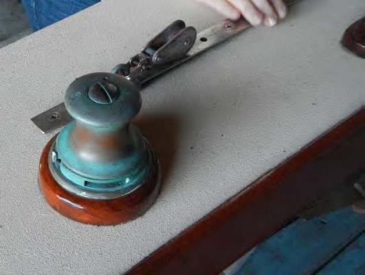
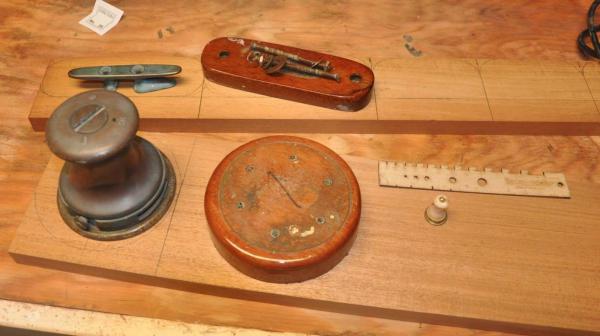
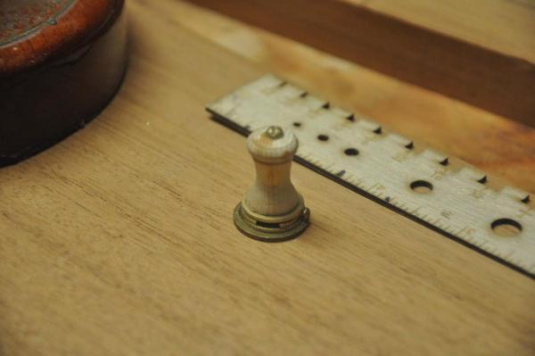
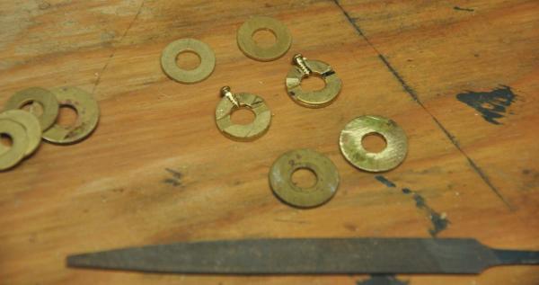
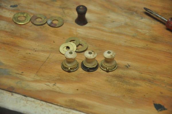
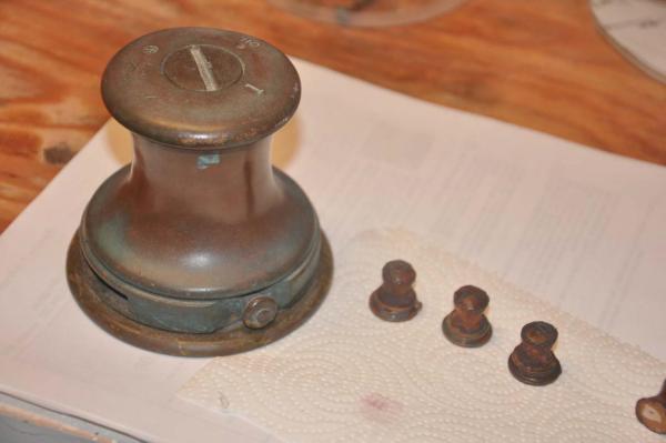
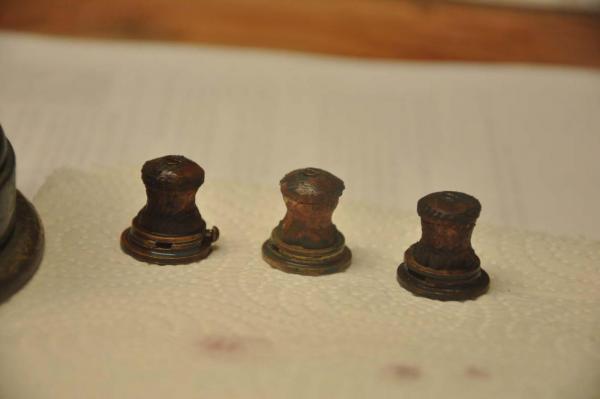
Hi All. During the final surface preparations and completion of the hull, it is important to start figuring out how to make or procure all the items needed either to replicate the boat or to make it sail. If you follow the number sequence of the photos, one can see I bounce back and forth from hull production to fiddling with the fittings. I think that is normal, but it would make it harder to follow this log. Therefore I am making two postings. As stated I am doing these to help demystify the process to encourage more entry level participation. That way maybe we can build a fleet. My full size boat named BITTERSWEET is the template for hull one of this two hull build. So as we are heading into winter, plans are being finalized for the completion of restoration to the real thing. To help figure out the modeling we shall be using BITTERSWEET My first challenge is to make three winches in the classic bronze material to the older 1940ish design. Here is the starboard jib / spinnaker winch on BITTERSWEET. Oh the stainless jib track and unmatched jib block are also going away. all tracks and fitting will be aged bronze. This requirement means finding different way to achieve that. As part of our work, we shall add a third winch to the foredeck to better facilitate crew handling the jib sheets from that position. To do that we need to procure three fittings, one winch and two jam cleats as well as to make Mahogany bases. Here you can see I have procured Honduras Mahogany and am making the real size plates. Now to make the scale winch I chose to mock one up. Look in the photo and you can see my first attempt. Here I turned a 1/2" dowel to the shape of the winch barrel and used brass washers to build up the base and body. While at the NRG session in Mystic last week, I discussed options with many folks. make a mock up that someone could use to make a mold and then use resin make a mock up that someone could use to make a mold and then a second mold to use Britannia medal...$$$$ work on my CAD skills to progress into 3D. then down load a model and sent it off to a printer. again in resin..ok but in nice bronze..$$$$$ get someone to turn the barrel in brass and continue to assemble as the mock up.......this is my first choice. Oh an I also want to improve cad to be able to do 3D In the mean time I chose to make up three as place holders. Hopefully they won't have to go to sea. here they are raw and ready to finish. finally here they are with a quick attempted finish. per recommendation of Nic from Blue jacket , they are painted the red brown [ called leather brown on the can] and then covered with a green wash. i see here they need more wash, but again " place holder" I am sure we are coming back to these. Good news is other boats may not have the same type of winch as racers like the more modern efficiency of sleek black and chrome Harken fittings. cheers
-
Giorgio Really looks good. In recent reading about schooners in this period, the new boats might have gone out brand new with both decks and deck houses oiled. Soon after the the deck houses were usually painted out . then the smaller elements were often white. Sometimes the waterways and house roofs were dark. Some plans even painted the working area of the decks. My point is from my brief research, I concluded you can chose what you like and be right. I look forward to you updates. I love the old schooners and yours shall be fun to watch Cheers Jon
-
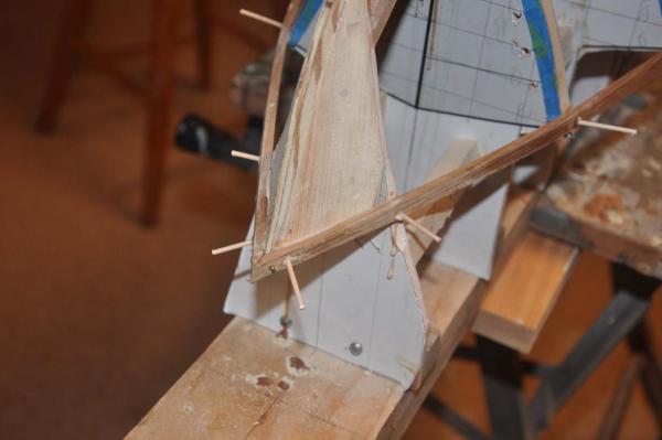
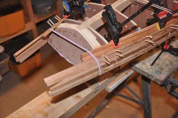
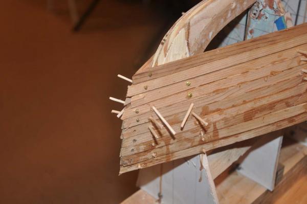
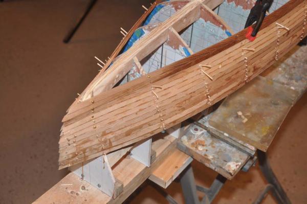
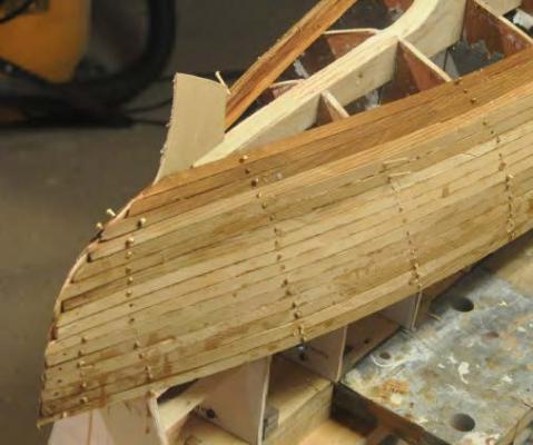
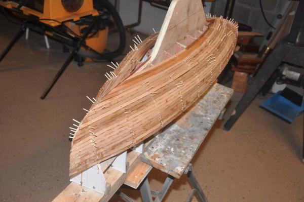
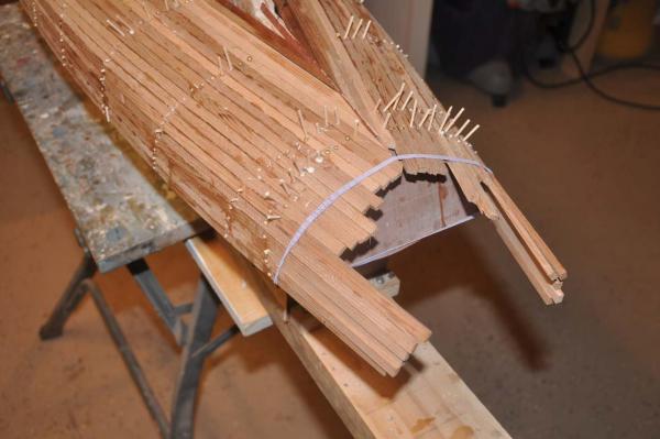
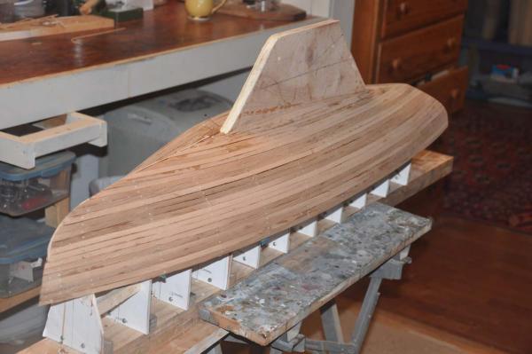
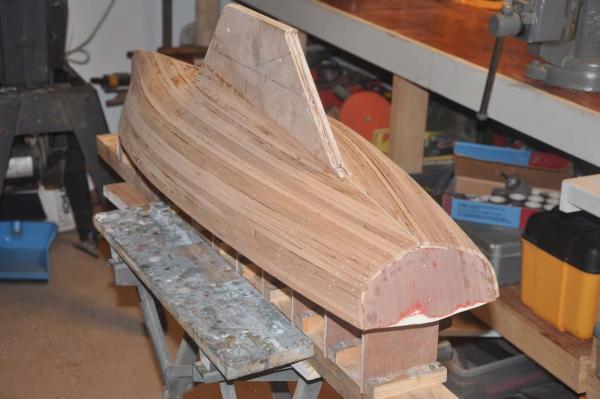
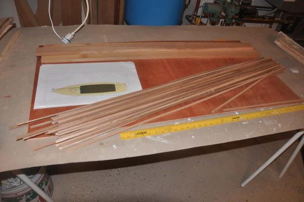
To all those who some day would want to build your own model BHOD , I hope you find the planking step as much fun as I do. We have had a busy week here in the harbor as work day came at the club and the final club boats were tarped up for winter as more friends left for warmer climates. I even put our little pond dock to sleep for winter today as well. The chase boat is on its sleepers almost ready for a winter nap. Despite all of this. I want to get come progress on this build before a few trips take up our time. The good news is we have spectacular color in the foliage again. Funny though that means we are into fall clean up too. Building this hull I remind all this is a proto type. I am trying to build it in a way that others can follow. That means others who are not experienced museum quality builders as so many are in this forum. The materiel is accessible and reasonable to work with. That being said there are definitely a few tricky areas. I learned some good lessons going through this step. These lessons will be a challenge to hopefully solved and avoided in the second hull to be started next month. here we go step 2 Planking Picking up where we left off, the first need was to carve up a transom with blocking and get the bow blocking properly aligned. to do this one needs to extend the shear plank and test the alignment and sand and get it right. here I had sanded and re-sanded the blocking as I fit the planking to the forms about four times, but I think we are there..... See the nice fit of the planks at the tip of bow...ha ha stand by for the lesson learned. the transom went pretty quick. I like soft pine for the blocking like the bow. It is easy to sand, glue and drill into for screws and toothpick pegs. For this prototype I plan to have a painted transom. If one chooses to have mahogany, this would be the same but it must be about 1/8 inch further forward to stay inside the boat length. [ the mahonagy would go on after planking. I would use 1/8 planks glued together., similar to those planned for cockpit combing later. the edge would be exposed and real ones are also laminated. I will try it on hull 2. I said I would move along and only record things that are different or unique to this build. That requirement did not take long. There is quite twist in the planking. The planks will be visible on the inside of the cockpit, so I chose to run planks all the way through as long as they ran off the transom and needed only one cut end. Due to the multiple twists as well as side bending, I ended up having to use temporary screws to hold the wet planks to dry to shape.....that is another reason for solid blocking at the bow and transom. I did cut the planks when I got below the floor line. we have a concave..."reverse curve" at the bow. Very quickly I found a need to use several screws on each plank. The planks are tight on the inside due to the curve and loose on the outside.... that is fine. The outside will be filled before fiber glass. Using the 5/16" width gives a good enough curve I found on previous hulls and so far so good here. Again this makes this an easier process to build. Checking the plans the planks are about 5 inches by 1/2" cedar. that would mean 3/4 wide and just over 1/8 thick. I am not sure what material could bend at that scale. i wanted to use cedar, so I do not apologize for just under half size planks. ....OK here is our first lesson learned and possible oops. The reverse curve pulled apart the three planks at the stem as I screwed in tight at station 0.. The fix was to file and insert a 1/16 plywood cut to form of the stem. I then ran the piece all the way to the keel, so each plank would end on this piece. This trim piece should give a crisp line after sanding. the oops was not knowing its need and not having it all the way around the bow before planking.. hull 2 shall have it!. I had assumed i could achieve that by sanding......we'll see. here we are progressing. 3 or four planks are glued and drying while the next 3-4 are being installed, secured and hopefully drying to shape. here I have installed a filler piece as well. I always planned this one as the dimension across the keel is perfect at two planks plus 1/16 inch center trim piece. well here we are all planked and one rough sanding done. There are a few items loose and then we need to figure out how to dress up the bow. where the trim piece was added it seams simple. controled sanding and filing is my approach. what ever we do gets covered with cloth and glass then filed sanded filled etc. we'll fix it. here we have cut and sanded planks back to the transom. If we were going to use mahogany I would use 1/8" solid boards. they would be added to this structure as one wants to cover the ends of the planks. One would need to shorten the placement of the transom that 1/8" *** part of the planning. OK cheers
-
Michael Thanks for your comments. I am enjoying working on both a real 1941 boat and making a sailable model at the same time. One challenge will be to keep it simple, so I can encourage others to build one. For me simple is OK but I want it to be accurate too. I will be struggling to make bronze fittings. Cheers
-
Mike I just enjoyed a good hour reading your log. I am trying to to learn as I go and there are so many great ideas within your work. First is the integrated lead keel. Then the beautiful metal work. Wow Thanks for sharing. Jon
-
Patrick I have had them three times. Once every 18 years apparently. Last time was while on assignment in Brazil. That was a story.........Anyway they are awful but afterwards lead to greater rocking chair discussions. I sympathize sincerely, wish you well and welcome you to an elite group. Cheers Jon
- 1,083 replies
-
Patrick I am always amazed to see the challenges you give yourself with the small scale. I will watch and wonder. Good luck Jon
- 1,083 replies
-
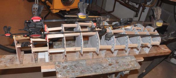
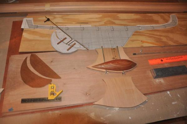
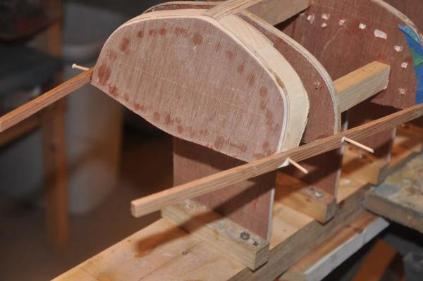
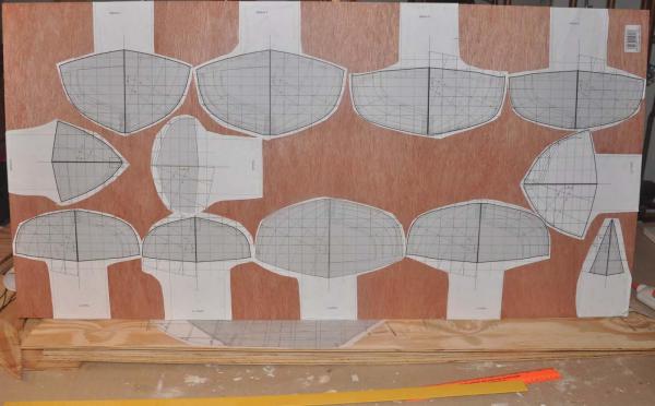
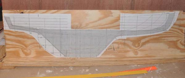
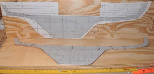
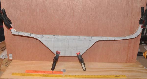
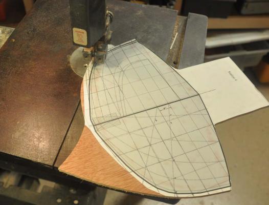
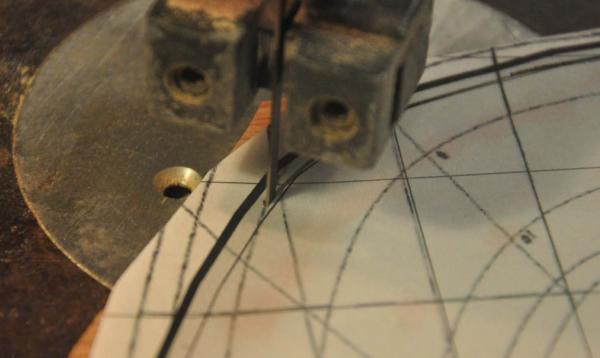
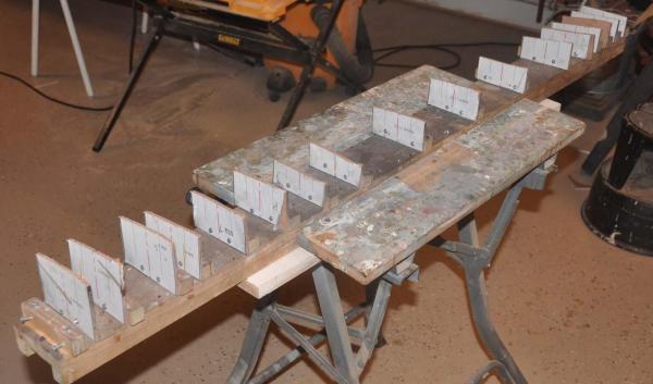
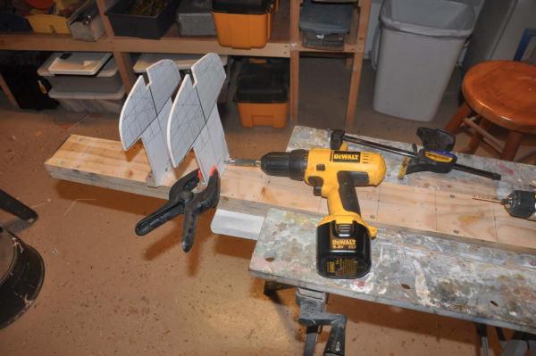
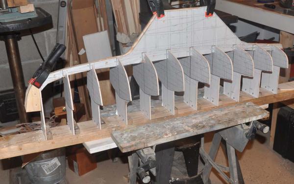
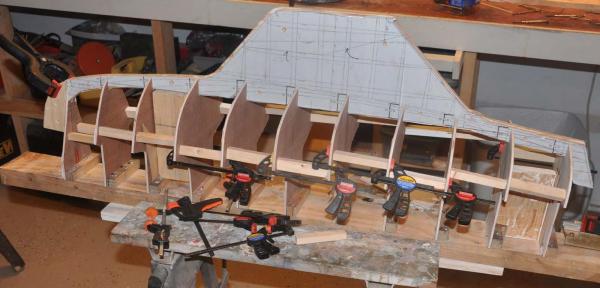
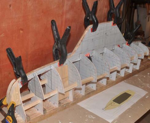
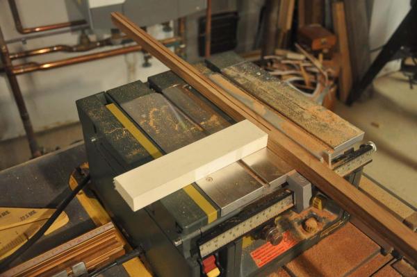
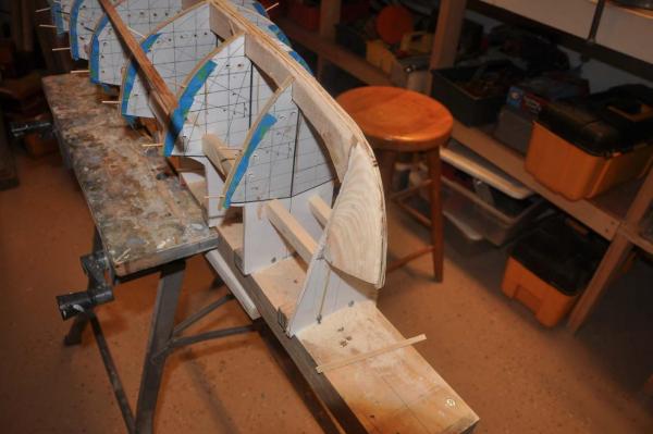
Building hull # 1 stage 1 get ready to plank Well here we go again. I thought I could go quickly through these steps as they are similar to other builds in many ways. I want to note where we may find differences because of the unique large scale or other aspects of this boat design. One example will be the unique rudder profile where it " nests" onto the aft edge of the keel. I need not to rush too much though, because at this large scale the crisp lines of the bow stem and transom are key to a successful build. off to the shop here I took all the stations and set them up so their legs would have nice square cuts on one sheet of $5 luan. It is nice only having 10 stations this time. I also prefer having the gray shading added to the printout to make them more visible. Here I am going after scale as well as practicality. The typical fir 1/4 plywood is actually thicker than that. if you laminate three of them you get to 7/8. it's OK for a large fishing schooner, but we are looking to hold 4 inched in scale. The birch plywood at .19 is better to sandwich the .26 fir ply and give us 5/8 thick keel. Therefore we keep the strength, straightness and stability of 3 play and honor the tighter scale. Also the birch finish is nicer to work with to get sharp edges. I chose to keep the center fir sheet as it will house the attachement for the lead keep which hopefully shall be integral. In this photo I screwed two together using one printout to cut them out just smaller than the center plywood in most areas and bigger for the concealed rudder detail. [ hold for later] here all three are together for fit up. Now we cut out the stations. We cut close and then dress with a side disc sander. Here is a lesson learned from my past. Use the CAD to offset a line to cut them out smaller by the planned thickness of the planking, so that after planking we are back to the boats true lines. This step saved much filing. here is an old friend. We need a building board , so I took the one from the recent big schooner Charlie. wow 21 stations on that one. We shall reuse the blocks and with a little light sanding layout on this old board is fine. This is the standard method to set the block square and then attach the station leg and work progressively from one end to the other. Here we have all ten stations set and the bow blocking fit up. I am holding on the transom for this step. Here we add temporary blocking for all the stations. Simply glue and set in place. they all get knocked out during planking. Our first glue up.Due to my previous experience I glued the laminated keelsons and the spacers. I did not fill the station slots with glue. The next day we rip out the clear cedar planking. As before I cut down 1"x 6" stock to 5/32 by 3/4 and then split the 3/4 as in this photo. Doing them myself on the light duty saw they still have some deviation and I need to figure out how to avoid it. One of the club boats is cedar and I will eventually need to plank one exposed, so I must get access to a cabinet maker saw to make them perfect. the other alternate is make them thicker...say 3/16 and then get a gauge sander. Here is my new stock. I believe for a fiber glassed solid color hull this is just fine. I cut 5/32 so I have a true 1/8" thickneww which allows good sanding for shape before glass. this step is not complete but is the final step before planking. I have rough carved the bow blocks. Spanning some loose planks I see I have more to do. the sub ribs are 1/32" strips of birch plywood. They are glued to the stations below the floor line where the remaining stations shall become the default floor beams. see the drill holes to facilitate the cut out and removal of the stations[ forms]. I also saw cut that floor line about 3/8" into the station to help with the break out. the blue masking tape is to separate the sub rib from the station when it is knocked out. I will then add fake inner ribs to theses sub ribs and then in between to replicate the design. I need to remove paper from all lower stations and keelson that shall remain before planking. it is much easier now then later. lesson learned is the keelson was not perfectly located as to height in the transom area. I could have sanded and fixed but chose to carefully remove two stations and deepen their cut outs, so the keelson could lower to the right position for the planking to come right over. That is why on the first glue up I did not glue the station slots. Now that all is set, I did glue them. I've definitely got some more work but soon I hope to set some planks and final align the bow blocks and stem and then set up the transom prior to planking. cheers
-
Thanks guys. I enjoy the project and putting together the log. I am going fast on my first hull to get to the hard stuff that needs planning and figuring out. The second boat will be better in all ways. I will include it as part of the log and hopefully it will fix things. I can share some lessons learned to as hope in the end to encourage some folks here to build one and race. then I need to figure out how to make a replica fiberglass with no ribs and aluminum mast. thanks for your support
-
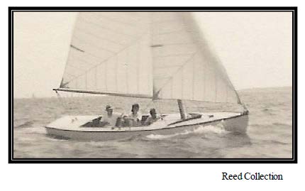
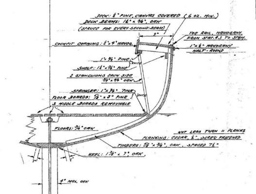
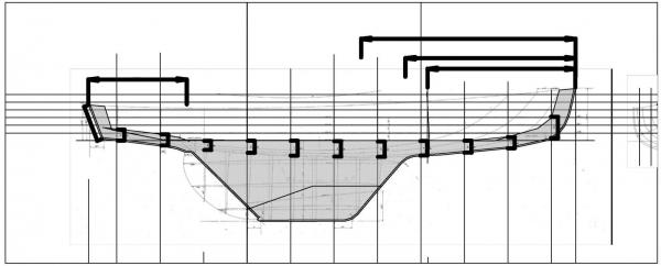
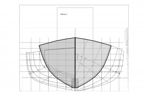
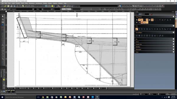
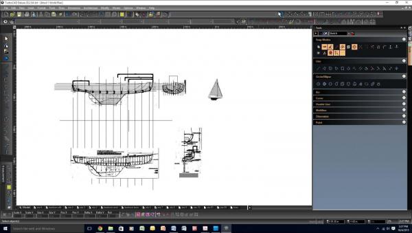
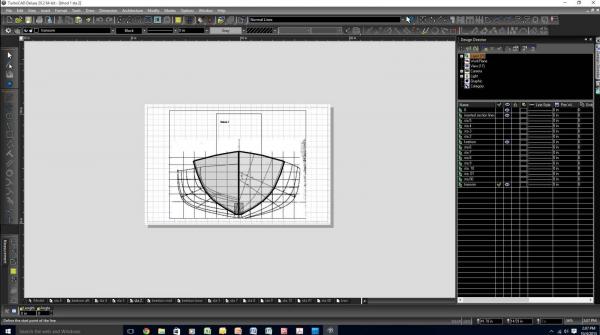
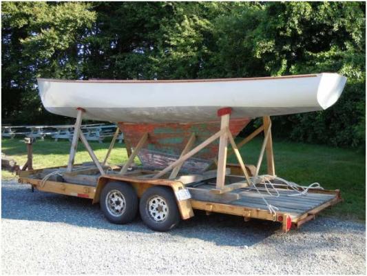
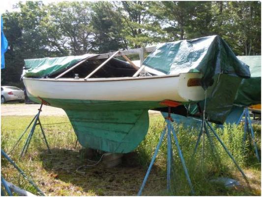
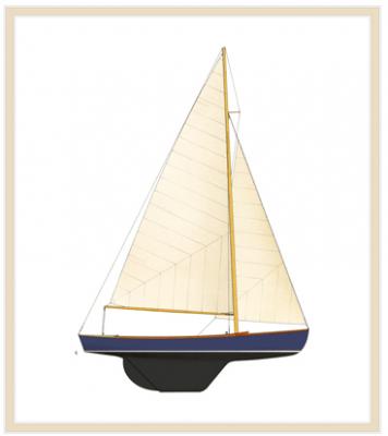
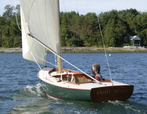
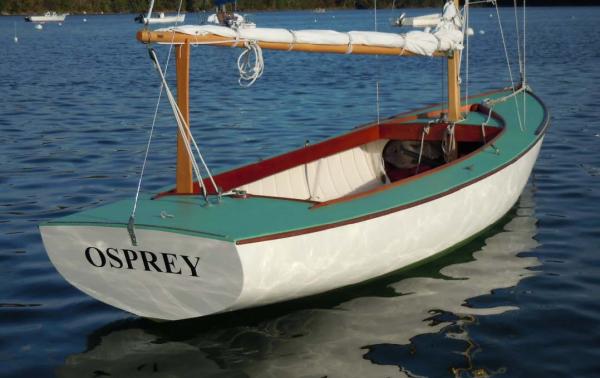
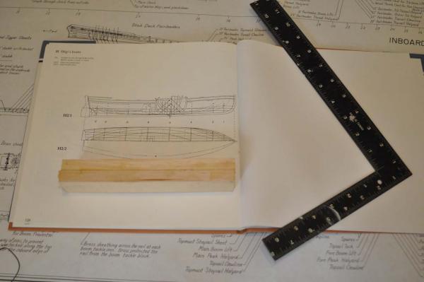
This build is to be a prototype for potential group of RC boats to race at the Boothbay Harbor Yacht club. First let's discuss why this might be a fun and useful project. LOA:21' LWL:18' 9" Draft:3' 6" Beam:5' 6" Sail Area:227.00 sq ft Displacement:2,100.00 lbs From Wikipedia "..Geerd Niels Hendel (14 January 1903 - 30 March 1998) was a naval architect and native of Germany. He found success in the United States becoming a prominent yacht designer who had a hand in an America's Cup victory in 1937. In 1935, Hendel became chief draftsman for the legendary naval architect Starling Burgess, who at the time was living in Wiscasset, Maine, and working on various projects for the Bath Iron Works, in Bath, Maine In 1936, Harold Stirling Vanderbilt engaged the Bath Iron Works to build the America’s Cup Defender Ranger, the greatest of all J-class yachts. Geerd Hendel worked with Starling Burgess and a young Olin Stephens on putting together the working drawings (see Olin Stephens’s book, All This and Sailing Too). From his work on Ranger’s aluminum masts, Hendel became one of the early advocates of the use of aluminum in yacht building. That summer, Hendel became a US citizen. In 1938, Hendel designed the 21-foot fin keel sloop known as the Boothbay Harbor One Design, the culmination of almost a decade’s work of designing, building, and then testing his ideas for fast racing sloops. Geerd Hendel and Starling Burgess actively raced the Hendel Racing Sloop during the years leading up to World War II. ......" There is more history available through the Boothbay Harbor One Design association, which is hosted on the web site for the Boothbay Harbor Yacht Club.. http://www.bhyc.net/bhoda.html The short version is the wooden boats were built in the local area through the 1940's and 50's. In the 1970's fiberglass hulls were made. My understanding is they were using cork within the glass element instead of cold forming method . Starting in 2007 two wooden 'original' design were built through the Brooklin boatworks. They took the original design and rebuilt the documents and molds. The first build boat was named Eight Bells and she is in Boothbay Harbor. the second build included much work at wooden boat school. She is named Osprey and is easy to find on the internet as it is looking for a new home. Since 2009 a few wooden boats were skinned with two coats of 1/8 cedar veneer and resin. There is a practicum on this process for the boat Bittersweet, No 20, done by the Brooklin boat yard. Finally David Nutt has built a few cold mold form, [4 layers[, at his boat works in Edgecomb Maine. All together there are between 50 to 60 of these boats still sailing and many are still here. There are also several very similar ' sister' boats including the Hodgdon 21 [built by Sonny Hodgdon] also wood hull keel boats, and the Christmas Cove 21 all fiberglass. A similar 21' boat class also the Great lakes 21 lives in Ohio. I am now the proud owner of Bittersweet No 20. I am hoping to learn more of its History. I am told it was owned for many years by the Reed family. . I found this photo on line and see the extra long fore-deck and after deck, an option in the 1938 design, that matches Bittersweet, so I think this is the same boat. ...Here are before and after images by Brooklin boatworks showing the 1941 built Bittersweet getting her new skin. Note the white transom? Part of my research will be to understand when was that changed from the original Mahogany design. ...Here is the post skinning look at Bittersweet. Still lots to do. The new owner decided to make her a beautiful dark green. He sailed her a bit but she currently is in a barn ready for more work. The plan is by next summer we shall see a new white interior and rigging all ready to resume racing. Modeling As to modeling, this project is not a complicated whaling ship, bark or multi-masted fishing schooner, but it is a real classic Maine sailing design. There are many families with long histories of this boat and a thriving youth sailing program all in the same place. Races are Wednesday afternoons and 5-6 weekends through our short summer. They are perfect for fun sailing in this great harbor. My goal is to show up next June with two working radio replicas to race at the club. The first two will be proto types. Ultimately I need to have a choice of either a wood design with wood mast or the fiberglass [ same lines] with an aluminum mast. For now that is shape the spruce and paint "aluminium" but we'll see when we get there. They are also great for a foggy day dockside. The first step in the build is to get plans. Fortunately the Maine Maritime Museum in Bath has a complete set dated 1938. I am aware that new drawings were created for Eight Bells a few years back and I am looking for them too. I also have Bittersweet and a dozen others to photo and copy. A big challenge for Radio sailing is the fact the jib clews trail aft, past the mast and shroud. Most radio sailors are modified and jibs are redesigned to be a ' self tacking' style so like the Main sail it is only in and out, geared by one pulley to be 50% of the main and can therefore share the same servo. We shall get into that as I have the same issue on the other boats I am working on, Charles Notman a 4 master with a flying and outer jib and the Dancing Feather a Boston Pilot schooner with Jib and flying jib. I took the plans to Staples to get scanned into PDF's. I then took the image I want ....say station lines .. and saved them as a jpeg. I can then open it in Adobe Photoshop Elements where I can rotate by fractional degrees and using the grid get a plumb image. I then save as a new PDF. I open the new PDF , take snap shot image and paste that into Turbo Cad Deluxe 20. To build the model, I take the section lines and tweak them to align with the Keelson / side view section lines. I then added the detail framing section and align it below to take on the detail and better understand the build. Similarly I include the framing sections in scale to the lower right. Now I need to build the ten station sections and transom. I go to the station lines and add layer by layer, tracing the line and then using mirror copy to complete each station mold. I then add common legs to attach to the building board and cut outs for the keelson. I set up a page for each station with its unique named view in the model and viewport on each page. Finally I offset inward the equivalent of the planking so when I finish the planking, we are back to at the final shape. Here is what gets printed out and glued to the luan plywood. Keelson assembly planning Now we have all the stations we need a keelson assembly. This approach takes us away for scale modeling replication to building a model that will sail. To understand please look at the image of the boat framing including the 'floor' sole and keel attachment. One can see in this framing section there is nothing but bilge under the floor except for the floor timbers. For building a static model there is no problem, but to sail we need to transfer to load from the hull into the keel. It might work but since we can not see below the floor, we shall use that space for structure [ nee the keelson]. We will discuss more as we build out the detail in the open cockpit. The keelson assembly.... We need floor timbers to support the flooring but also we need to add and extension to the keel.....keelson.. that goes stem to stern. due to scale and size of printer we need to make this in three printouts and then attach. here is full scale of the aft section of the keelson we are ready to start the build
-
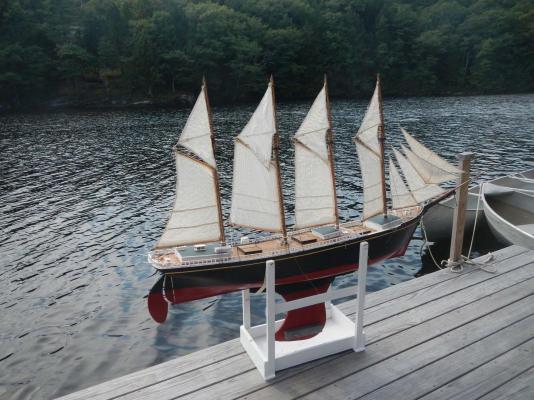
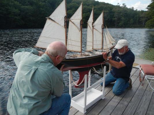
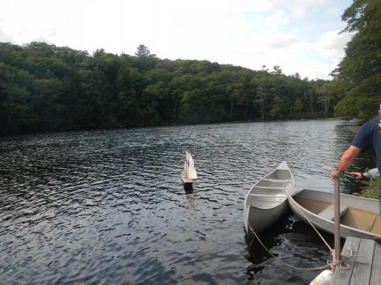
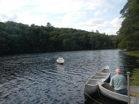
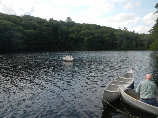
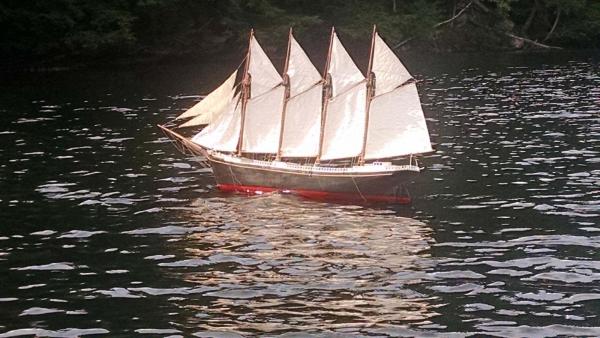
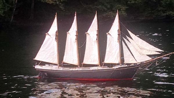
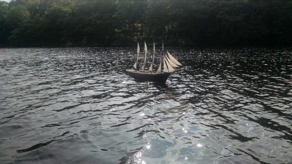
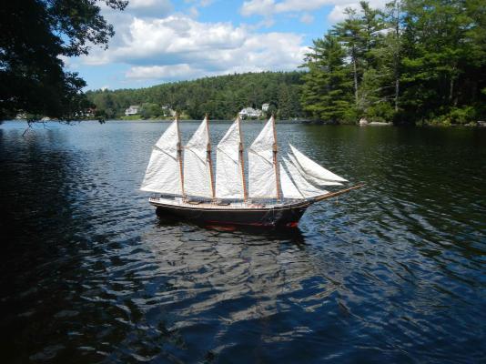
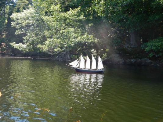
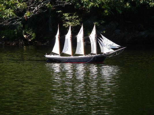
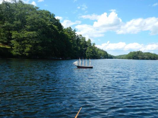
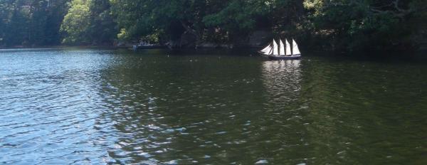
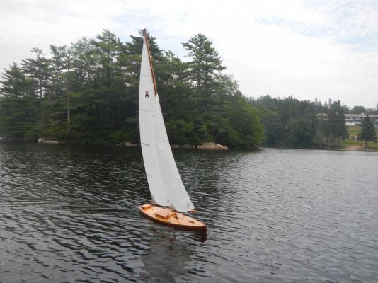
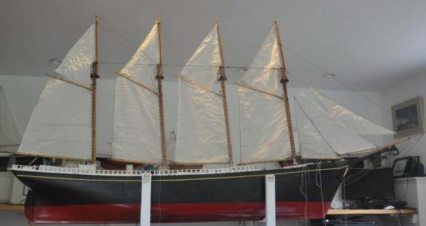
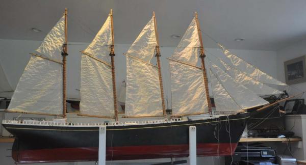
Ok here we are for our second sailing. To get ready I did a shake down of the running gear. My focus was first time issues with the sheets coming loose. I secured them all and got them all acting right. Thus I felt more confident that I could pull them in tight and possibly get to go up into the wind. Well here we go all stuffed into the car. Somewhere in this operation we lost one yawl boat davit and the head stay...oh well This is a great place to sail. It is less than 100 feet from the car to the dock. We attached the keel and then lifted her up and into the water. It definitely takes two people to do this. She took right off and after a cheer I got quickly into the chase boat. On with the joy stick and wow she turns Ok fine for this maneuver and now the sails came right in like they should. This point is as high to the wind as we can get. After several tries she would not come about, so before hitting land we jibed giving up some turf. We went back and forth about 4 times. It was always nice to watch but each time we had no ability to come up into the wind and each time slipping down the lake as we jibed around. This clearly was my favorite shot as she is coming toward you. A little photo shop with this image could be great fun. finally back at the dock. the rear admirals are adding up style points. They approved and a cold beer was enjoyed. This time I gave my camera to my rear admiral. All I can say is video is not in our immediate family arsenal. Some day we may get there but there are so many other things to do. I have been thinking a lot this past month and through this sailing experience as to what level to take Charlie now we coming out of sailing season. It truly is a joy to watch her go, but it takes two or more people and chase boats, she won't come back to the dock on her own.......yet. My current plan is to fix all the minor damage, add a few more missing details but not go to the next level that would prohibit taking her out again. Next year I will be getting smarter with radio sailing in general. I have three other projects now starting and I need to have several boats " more practical" to sail. Then I can better tackle options to get her balanced. example...remove the jibs and see if that helps come into the wind. I will be doing some other projects and open a new building log for them. I will make a post here after I start them. I will update this log less frequently through the winter as I shall continue to fix things [ I have 6 more turn buckles to make , need to fix up all the rigging etc. part of the struggle this summer is that it takes a bit to organize where to go and sail. I need other people and access to a chase boat. I can always go to our yacht club, but it is better with a radio boat that with sail away and back to the dock. Also let's face it; we all underestimate the number of things we must do in the summer and these are the fasted months of the year. I will need another sailing season to try to sort it out before I finish this one up. cheers
-
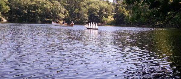
OK here we go First up is to get the radio on and the chase boat ready. Our new Catspaw sailing dingy is just the thing for this small lake. it takes two to lift her into the water. Off she goes! Unfortunately the wind we had yesterday afternoon is not here yet today. We must recall though I have read that the difference in this scale of speed is about 5 times. Therefore perhaps light air is safe and good thing for the first time out. With light air she drifted a bit south along the shore. Here we are chasing CHARLIE away from the shore. Our Catspaw dingy is 12 feet long, so the size of CHARLIE is easy to see and enjoy. Who is chasing whom? This is one of the photos for my shop. She jibed and then worked a bit off into the wind. we got out a bit and she looked a bit better. wow she got going a bit. I was trying to do video so not so many pictures. we tried several times to come into the wind and she would not do it. She did jibe well and quickly. Today the light wind is not a good test of pointing. We must remember in truth the bigger 5 and 6 masted schooners would sail one tack to Bermuda and then jibe 270 degrees [ ware around] to get on course for the Norfolk Virginia coal docks. Ok shake down went sort of OK. We could not come about or point very well and had to tow back up wind. More work on the radio-servos to trim up. On the dock we ran out of juice playing to see how to improve the jibs, but I suggest that was due to not changing to fresh batteries before launch. I had pared two together, these servos require 6 volt batteries, and in the shop they last for a few days of testing. damages: one sheet came off each the main sail and the foresail. those were unglued knots. I had removed the Bousies at the last moment and simply tied them off. some how while grabbing the stern, the wheel box and wheel broke loose. fortunately they stayed on board. one turnbuckle came loose, but I saw it was not properly attached. [ it had broken loose the other day and I rushed the repair] we took some video but are worse than amateurs in that area. We will be on a friends dock in a few weeks and hopefully find more wind and be able to take some video worth sharing. The focus of that next sail will be to point up a bit and hopefully come about. My wife caught this image of the carry back to the house. My conclusion is that this boat [ ship] is not meant for sailing off our dock. I am not saying no but probably unlikely. In conclusion: we need another test with more wind and to be sure we are getting sail trimming. We shall continue to accept damage, but after a few more times need to decide the purpose of the boat. I would love to finish the rigging and all the lines, and then windows and stove pipes etc., but that will end the sailing days. The servos, sailing keel and stuff are the only added features, and once they are removed they can go into another boat. That was my son's recommendation. Make this one a good one to look at, that could sail and then make a more practical sailing schooner. I have to think about it as I plan my next winter builds. cheers
-
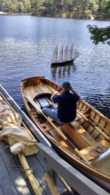
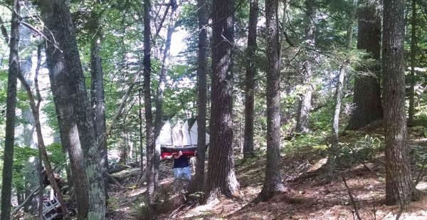
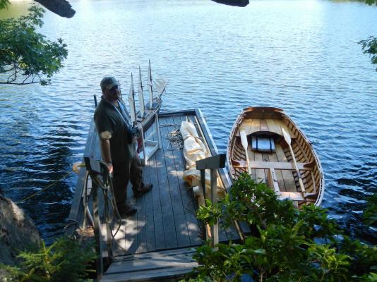
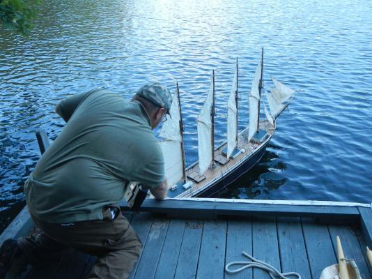
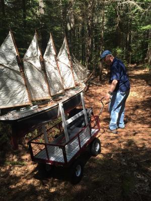
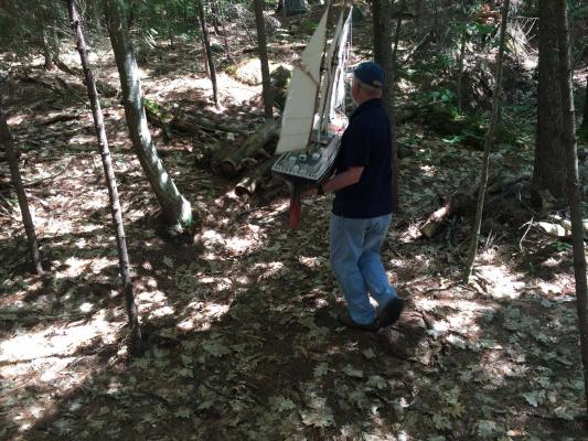
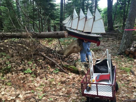
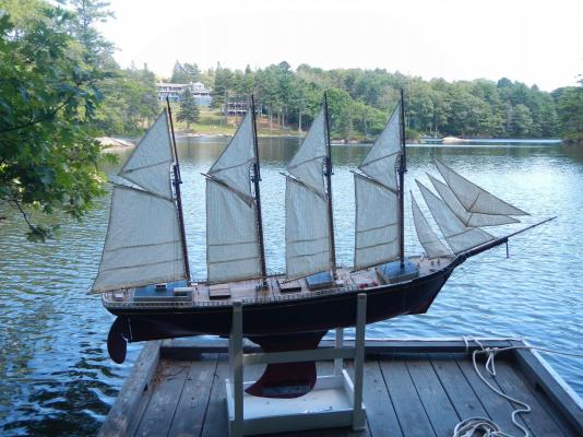
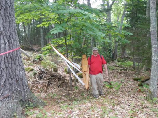
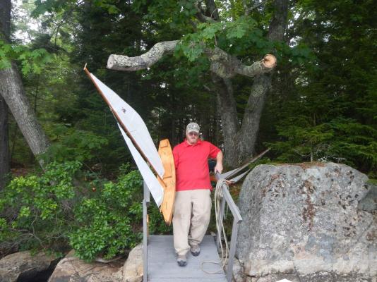
this is a test posting to see if new windows 10 plus its browser edge work we are loaded up and ready for the woods Here we go into the "improved trail" Here the trail gets a bit steeper Ok lets carry up and over the ridge wow that was fun......I slipped once on leaves. well here we are at a rest stop. I can see the lake We made it to the dock and attached the keel we are ready to try sailing the tension is building...right? cheers
-
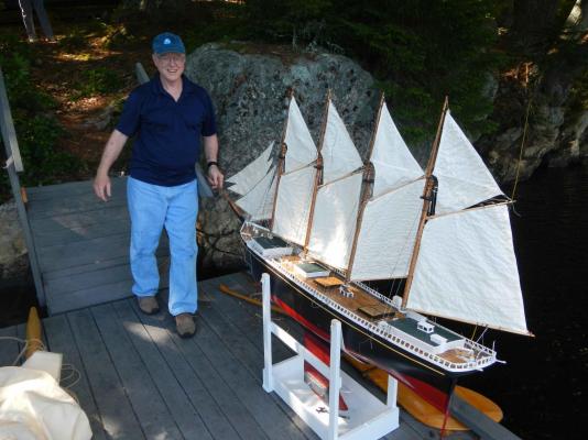
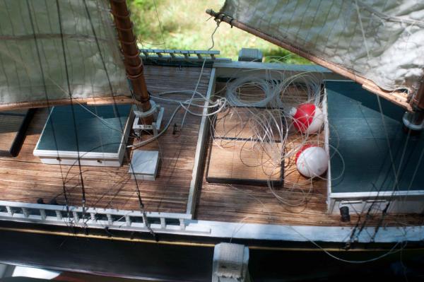
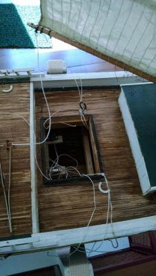
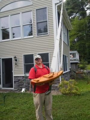
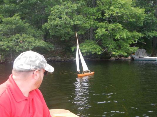
Well it is finally time to sail. Before we do however we need to test out logistics and tune up the radios. To do this I have waited for my son's vacation. He and I build hulls for classic pond yachts in 2001. I was able to take them out and finish the radios, servos, buy sails and rigging and get them done last summer before starting the big schooner. First of all we shall use them as the trial test. trail test of sailing in our local pond here my son holds up one of the pond yachts. we have trimmed the radios...he showed me how to both trim and reduce the rotations. here we are off into the woods. The trail is about 800 feet to the dock. stage two is successful and I say repeatable as walking with these boats to the dock went OK the first boat sailed successfully. We chased it in our boat but actually were able to control it quite easily. The second boat worked well too, and with a little added wind we were able to get it to sail right back to the dock. final set up for the schooner While trimming the servos and making final checks we found the loops failed as they should if overturned. I raise here a couple of issues. I was using rubber o-rings as I felt they would be weaker than rigging and better to give than a stay. When several broke earlier, I upgraded to carbone rings made of soft plastic. They are stronger than the rubber but fortunately broke before rigging. In the photo both the black rubber ring and the white plastic ring are broken. Unfortunately, however the sheets for the flying jib sprung and went deep into the boat. As also seen in the photo, I have undrilled the three sticks holding the forward pulleys [ that make up the servo loops] to get all the way in to retrieve the sheets. This can not be done in the field, and it took an hour or so to complete. I am embarrassed to admit this but all these months and not a few dollars into this, I added a safety line through the mid cabin port holes and around the mast below deck. I attached 50# test fishing line and a few floats. Our pond gets up to 50' deep and well...you know. [ as a follow up she sailed really well and I did not need and shall likely not include in the future with light wind.] just to share more examples of oops. For a moving model, the light rigging is so fragile. Here the chain on the jib boom and martingale broke while the cart [ shown in early photos ] was moving too quickly and I reached out to stop it. well next post will be the successful sail. we have celebrated. cheers
-
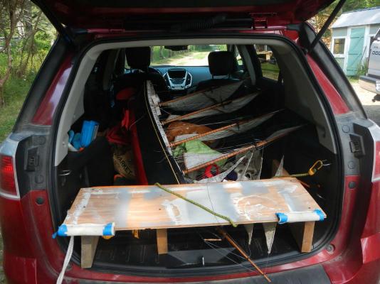
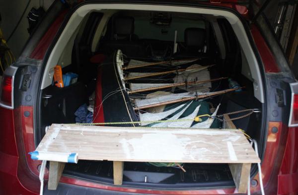
guys thanks for your comments on the radio. I am definitely over my head here. My son is coming from Arizona this week for the big sail. In Phoenix they use radios for RC tanks. They shoot each oher with infared....I think! He rewires everything and looses me with the vocabulary, but I am using the first of his fixes I bought on line a camera position controller made by Dionysus Design. This little device plugs into the servo line just before the receiver. the spring toggles are now track-able. So the rudder is left and right and the flying jib is up and down He said the toggle that "slides" for the throttle is a "lkjljkhlh". He will bring one and show me how to change the other so both work the same. I will still need one circuit on the controller if I use three controls. and two if i disconnect the foresail so it can have its own. Anyway as I wait for the sail I have been adding lazarets and things to busy up the deck a bit and make it better for the photos. I also solved transport by stuffing it in my SUV and building a frame to cover the protruding bowsprit as I bungee cord the hatch down. Fortunately I only have to drive about a mile or so depending on where I plan to sail. I took the ship to our yacht club men's sailing lunch to recruit interested folks to build some models. I hope I caught some interest. I was competing with the real thing though. again thanks for tips
-
well to all you computer guys out there.......I had an interesting problem this last weekend with my computer. I caught that encryption virus. It went through McAfee like butter..... it locked all my data files. Unfortunately my back up drive was connected to the computer and therefore the virus took it out too. It even went into the drop box account I have for sharing and infected shared folders generated by others. I hope I deleted them before anyone else went to get files. I think all is well there. Today I reformatted the computer and am starting over from scratch... I wonder if I will start getting notices again for the logs I am following. I stopped getting those notices months ago. I learned from searching this forum site I am not alone with that problem I lost all my pictures, pdf or ms office files for the last few years. as luck would have it i cleared out my two cameras last week so no back up there either. Fortunately for this build I have this log with selected shots and that is all. Oh well many things in life are much more important. It means I am starting again.....that has to be good . Now to Charlie Notman more time seems to be fixing than building these days as I build up nerve for the water. Moving the boat the starboard bow sprit chain broke. several clew lines and sheets all ripped off their pins retesting the servos and lines has been troubling, but I am pushing through. The rudder just would not work, one sheet tie ring came off its loop below deck, haven't got the fix yet I did get the final top mast says inplace As RC folks must know, radios are made for planes not sail boats. With two joy sticks one could have 4 servo actions but only one is slider [ the throttle] I have made that the main sail control. I then spiced the lines so the foresail and jib are now a loop, so they move in theory half of the others. 3 inches vs 6 inches That leaves the flying and outer jibs. My plan today is to leave them on a third control only for coming about if required. They will be fixed for most sailing pulled in a bit. The action will be to take the right joystick which is up and down sliding for the throttle [ main sails] and then swing it either left or right to pull sail from one tack to the other, but the sails will not be trimmed, as when I let go the stick goes back to neutral. Not sure that this will work. more next week
-
Hi Walter I am in later stages of struggling with same scale 1:48 to make a radio sailing 4 masted schooner. I will enjoy watching and learning from your log. I see you are talking 3D ..... wow. I have switched to Turbocad which is relatively easy to learn and not expensive. However i stayed in 2D for my build...the comfort zone I hope to learn from builds like yours so I can go to 3D good luck....i will be watching cheers
-
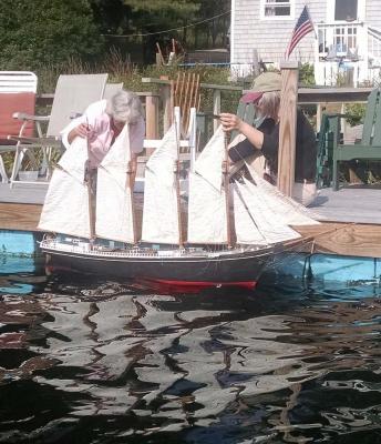
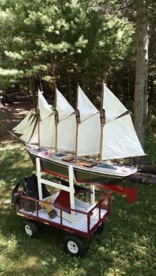
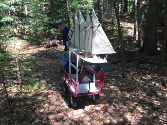
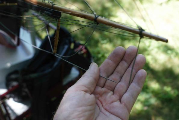
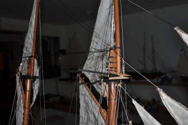
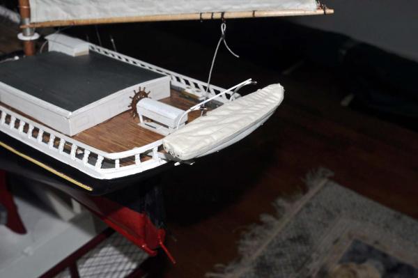
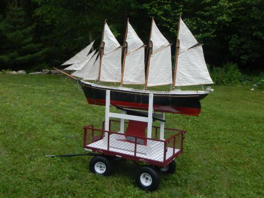
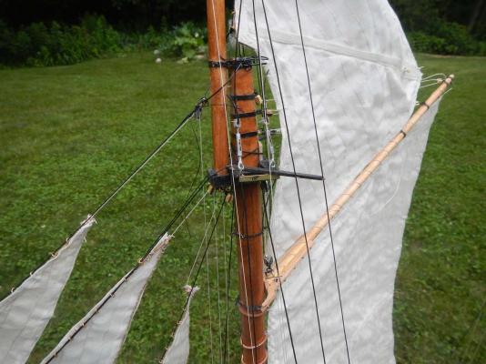
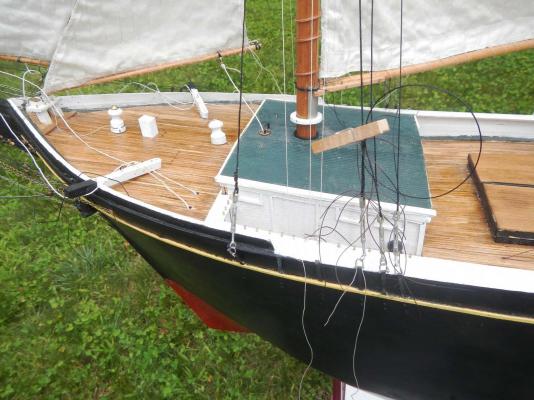
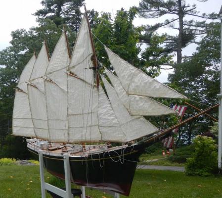
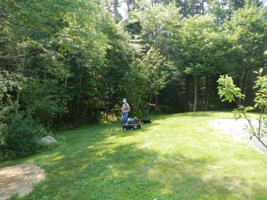
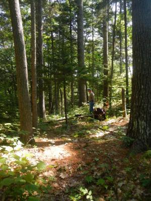
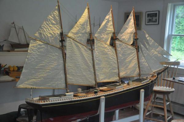
Well another week or so has passed and a little more progress has been made. I worked on readjusting the rigging toward sailing and then logistics for transporting. rigging I realized that for the topsails to ride the gaffs, both the fore and aft mast head bracing [ horizontal] and the top mast fore stays [ both in photo] needed to be removed. I have removed, tagged and taped them for eventual reinstalling. I then added the metal band connecting the cross tree tips. This detail reinforces the installation in real scale, but here also creates a seat for the spreaders. I made up the spreaders and added them, so far on the foremast. You can also see here where the outer jib halyard started out as a tied bass wood block and quickly failed. I have replaced it just like the main gaff halyards. I have taken the Bluejacket stopped blocks and used 24 gauge copper wire shackles to connect directly to the wire bale. Here you can see my scheme [ remember trial and error scheme] to sew one end of the shroud or stay and then slipknot the other end with a pair of surgeon knot ties. After a trail sailing if all is well, I shall sew and seize the second end. Please also note I chose to direct tie the sheet to the forestaysail boom and not use a bousie like the other booms. We'll see how that goes. I measured a 4 inch mid point here for this and the jib on a common servo. The other booms are all set at 6.5 inches. i assume that shall be reduced int he field and thus I used the Bousies. Thus the sail is midway out at rest. I can either pull it in or let more out with the servo........sounds good anyway much more work to go here. I have tried to do the flying and outer jib sheets a few times and will make up my mind how to do before the first run. My problem is there is about a two inch overlap of this sail and I need to figure if simply adding 2 inches of slack in the leeward sheet is the right amount, so the servo does not snag and pull on the stay. transport I went to the local farm and garden store and bought a wagon with 10 inch wheels. I put a plywood bed inside and will attach the strapped stand to it for transport. here it is just sitting int he wagon and we are pulling in a simple grass yard. I now keep the model in this wagon as shown in my walk out study. It is a good height for work and the handle helps keep one away from the tip of the jib boom. So as long as the wagon stays clean it is just great. i took many shots and share this one, a fun image in front of old glory taken on the 4th of July. here my pal and I are leaving the yard for the 800 foot trail up over a 50 foot high ridge to get to the dock. My daughter is visiting and followed to .....comment. this is a nice part of the woods and all is good. we tipped over twice going down some tricky parts, so there is definitely a need for a full crew to include enough hands to get there. fun I can't stop myself sometimes. I realized that someday I need a yawl boat. Most available views [photos] and designs are based on 1915 and after. Thus gas engines etc.are part of the deal. I am not focusing on making this model 1894, and will eventually have one with simulated engine etc. For now I chose to carve a block and cover it with canvas. I am not sure that a cover is accurate but I felt I needed to respect the need of a yawl boat and a wood block would have looked..... dumb? Here the assembly is roughed in. I likely shall not sail with the yawl boat and therefore save the lines and lashing until later. cheers
-
I wanted to give a brief update showing a little progress. It is summer here and time is quite pressing..... Here I have added the flying jib. that means 11 sails on and four to go. Here a half day later I added the outer Jib. that means 12 sails on and three to go. I have started fore and aft standing rigging with the key spring braces between the top masts. This set snugs up the mast a bit as they are loose in the stepping. The aft end is tight connected by sewing a splice to a shackle and using a seized knots at the forward end shackle to allow tightening. Eventually that will be sewed as well. I decided not to glue the masts in. One never knows what the future repairs may entail. Finally here we are. Obviously I am ahead of myself as so much undone. Note again the fun of the strapped stand gives the ability to set a tack. It is practical for moving sails out of way of deck work but also photogenic. Here we are on starboard tack and headed for the window. The spanker sheet is attached using a Bousie [ pekabe]. It's big and ugly, so if possible a slip knot for the smaller forward sails that have a common swing radius. Here is real trial and error. I should probably sail with this configuration. The three remaining sails are the top staysails. They are attached to the topmast stays and have sheets below the brace stays [ needing trip lines to raise for tacking]. I am not sure of the impact as I do not currently have plans for a 5th servo to trim them. They shall definitely be on the model post sailing, so we shall see how this goes. Perhaps if sailing is good, we can add them in the field so to speak and see how they work on a fixed set. Another big question is timing on all the standing shrouds. Once they go in place, access is extremely difficult. The masts are plenty strong, so it is an aesthetic issue. My thoughts are perhaps to add a pair [ top mast] only and try to sail. If all is good then add the rest and sail again all in place. I need to be sure i can come aboard later to add the nice things like windows and doors to the cabins, tackle blocks to booms etc. Call it shake down. Anyway I have a lot to do now to get ready for last week in July when I hope to ready for a trial run. Our summers are quite short here! cheers
-
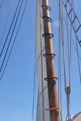
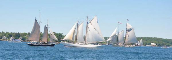
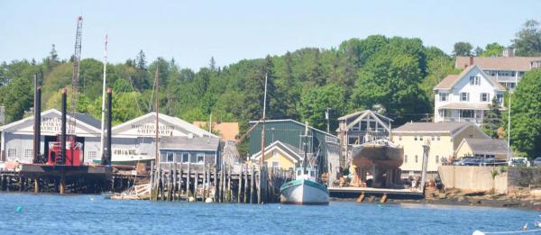
Hi Bob I am learning a lot through this project. I have two future projects to build and fortunately [ maybe] they shall be a bigger scale. I have the hull roughed out of Gerturde Thebaud in 1:24 scale and plan to build the Bowdoin a famous Boothbay boat also in 1:24. We have our windjammer days yesterday in Boothbay Harbor and I thought to add a few photos for fun showing the schooners coming into the harbor. Here are four schooners of the group all in front of us just outside the harbor. Note the Bowdoin is the larger one in the foreground built in East Boothbay in 1920 here is the schooner Ernestina-Morrissey at the Boothbay Harbor Shipyard where it shall under go a major refit. She was towed from New Bedford, Mass. a few months ago....very exciting here is a reminder of a big lesson learned for me. The mast hoops on this photo are on the LAZY JACK a day sailing schooner here in the harbor. We like to ride her and join in the parade of schooners. I add this as I am now chagrin that the little copper mast hoops I have chosen to use are just too tight on the masts. I don't plan [yet] to change them as that would be a major issue at this point, and they do work. Their color seems OK and they do slide around, but they are definitely not as loose as they should be. A few on the foremast [ which is a hair bigger than the other three masts by design] have torn in the multiple handling and I need to resew them. Once again in static modeling there is no issue I have attached my first [ large]sheet to the spanker and will be focusing on that going forward. They need to be adjustable. cheers
About us
Modelshipworld - Advancing Ship Modeling through Research
SSL Secured
Your security is important for us so this Website is SSL-Secured
NRG Mailing Address
Nautical Research Guild
237 South Lincoln Street
Westmont IL, 60559-1917
Model Ship World ® and the MSW logo are Registered Trademarks, and belong to the Nautical Research Guild (United States Patent and Trademark Office: No. 6,929,264 & No. 6,929,274, registered Dec. 20, 2022)
Helpful Links
About the NRG
If you enjoy building ship models that are historically accurate as well as beautiful, then The Nautical Research Guild (NRG) is just right for you.
The Guild is a non-profit educational organization whose mission is to “Advance Ship Modeling Through Research”. We provide support to our members in their efforts to raise the quality of their model ships.
The Nautical Research Guild has published our world-renowned quarterly magazine, The Nautical Research Journal, since 1955. The pages of the Journal are full of articles by accomplished ship modelers who show you how they create those exquisite details on their models, and by maritime historians who show you the correct details to build. The Journal is available in both print and digital editions. Go to the NRG web site (www.thenrg.org) to download a complimentary digital copy of the Journal. The NRG also publishes plan sets, books and compilations of back issues of the Journal and the former Ships in Scale and Model Ship Builder magazines.


