


KevinR
-
Posts
214 -
Joined
-
Last visited
Reputation Activity
-

 KevinR reacted to captainbob in Rainbow by Omega1234 - FINISHED - J-Class Racing Yacht
Patrick, I never knew that the J Class America’s Cup yachts were really “yachts” with fine living quarters below decks. I thought they were like the 12 meter boats that are pretty much empty hulls for sail storage. I wouldn’t mind living on Rainbow. Your model shows her as a fine Yacht.
Bob
-
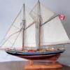
KevinR reacted to Omega1234 in Rainbow by Omega1234 - FINISHED - J-Class Racing Yacht
Hi everyone
Hope your week's been going well. Rainbow's progress continues...my main objective though, has been to concentrate on the major bulkheads and cupboard, etc. Once I'm happy that these are in place, then I'll start on the other details, such as the doors, mattresses, sink, galley, etc.
I hope you enjoy these photos.
Cheers
Patrick
-
KevinR reacted to jct in 18th Century Longboat by jct - FINISHED - Model Shipways - mod moved
Glad to have you on board Kevin...should be a fun build
THX
J
-
KevinR reacted to JesseLee in Scottish Maid by JesseLee - FINISHED - Artesania Latina - 1:50
Added the Main Topmast Staysail. This was the last sail. Been studying another Scottish Maid build while I've been working on mine. They had some extra rigging that my kit didn't instruct & I borrowed some of it & added it to mine too.
Made an adjustment to the base. The sides were straight. I filed & sanded a little out to add some shape to it. I think it looks better now.
-
KevinR reacted to jct in 18th Century Longboat by jct - FINISHED - Model Shipways - mod moved
Hey all,
This will be my second build log. After spending a little more then a year on my Half Moon I thought I'd do something a little smaller. I had picked up the 18th Century Longboat from Model Shipways last year and thought it would fit the bill, this kit was designed for Model Shipways by our own Chuck Passaro.
The kit consists of laser cut basswood parts, basswood planking, dowels and all the fittings and hardware. Also included are some nice printed decorations to apply to the sides and transom, two pages of in scale plans and a excellent practicum written by Chuck.
Before I get into the details of the build I'd like to share a recent experience.
You may know that Chuck has a business making and selling model ship fittings, Syren Ship Model Company. I recently ordered some brass cannon barrels for a future scratch build project, and looked forward to their arrival. Which never occurred...seems the Post Office lost my order.
I contacted Chuck to find out what kind of package was used as I needed that info for a lost package claim, well imagine my surprise when they arrived today...not my original order but a second shipment Chuck had sent, totally unsolicited, to replace my lost order.
In this day and age this type of customer service is unheard of...and I believe noteworthy, this gentlemen has earned my future business and I hope my tale will prompt you to visit his site and maybe place an order, excellent product line and as I've stated superb customer service. Give the site a visit. http://www.syrenshipmodelcompany.com/
The Longboat build:
I plan this build to be pretty much be out of the box...with the exception of the paint scheme and the supplied decorations. I'm also toying with the idea of adding sails, billowing ones! but we'll see.
I started by cutting the rabbit into the false keel and gluing the keel to it, the frames were then separated from their backings and test fit... all of mine had a distinct stbd cant to them...this was easily fixed with some light file work. The frames were then glued up, once dry they were marked with a compass to indicate where the first stark will lay.
THX for your time and attention...Pics follow
J
-
KevinR reacted to mhmtyrl in Kancabas cargo boat by mhmtyrl - FINISHED
hello
I am Mehmet from Turkey-Ankara
I have recently started building Ottoman Cargo Boat, I also have applied some weathering, will attach more photos as I progress. I would be glad to hear your suggestions
mehmet
-
 KevinR got a reaction from JerryTodd in Sailmaking and Boltropes on Working Sails
Jerry,
Thanks for putting this tutorial together. Great information.
Kevin
-
 KevinR got a reaction from thibaultron in Skipjack by KevinR - 1:24 - abandoned
Hi everyone!
Thank you for stopping by and all of your advice and help. The problem is that the angle of the starboard side planks is greater than the port side. The distance from center line on the starboard is grater than the port. I was able to realign the mast blocks with the stem and keelson. I also moved the forward port side the the forward cabin 3 inches closer to the side. I will have to trim some of the planks on the foc's'le to try and hide the difference. I have only 1 deck beam to complete on the foc's'le. That is the very first one. I placed a stub mast and a temporary sampson post to get an idea of how it will go together. I have not glued in any of the deck beams. The are a couple of additional tasks to complete on the hull before I can glue them in place.
Disassembling the mast blocking.
Making sure the mast is straight this time.
It looks straight this time.
My current status.
Thanks again everyone.
-
KevinR reacted to JerryTodd in Sailmaking and Boltropes on Working Sails
I get a lot of questions about the sails on my RC sailing models, a surprising number actually. Since answering requires repeating myself a lot, I decided to plop it all into a web page I can direct folks too.
Sail Making
I wouldn't mind some feedback, questions will help me fill in anything I missed.
-
KevinR got a reaction from thibaultron in Skipjack by KevinR - 1:24 - abandoned
I wasn't planning on posting tonight, but I discovered a problem.
I planned out the mast and sampson post placement.
Then I started on the blocking for the mast. It looked pretty good and I was kind of proud about what I had accomplished.
Then I looked at the boat from the front. Something was not right.
When I placed a straight edge between the stem and stern post they did not match up with the center between the sides. The mast blocks are not centered over the keelson. They are off by 3.5 scale inches.
I was real tempted to chuck it and start over. But I have been thinking it over and even though I am disgusted that I did not discover the error sooner. I have to much invested just to toss it.
I am thinking that I can re-align the mast blocking so that the mast is straight. Hopefully it will not be obvious the the mast is off center by 3 inches.
So, I am looking for feed back here. Has anyone else had to deal with this? And Is this salvageable?
The big question is, can I live with this?
-
KevinR got a reaction from thibaultron in Skipjack by KevinR - 1:24 - abandoned
Thanks Marty, I am looking forward to, and dreading, building all of those gizmos. Unless something comes up, I plan on being at the meeting.
Patrick, The part of the internals I would most like to show is the Foc's'el area. It shows the bottom planking, the wood chunks, the strongback with knees, the cabin decking and interior, stem liner with knee, the mast and step and the sampson post and step. I plan on leaving the cabin hatch open so this would allow additional light for viewing from both angles. the more I think about your idea the more I like it. I will have to see if it can be done. The Foc's'el is a very crowded place.
-
KevinR got a reaction from thibaultron in Skipjack by KevinR - 1:24 - abandoned
Patrick, I sometimes wish that I could show of the internal framing. I too like the way it looks. I like the way you do the cut-away on your models.
I left off a "8 hinges" from the list of items I need to make.
A last update before the end of the weekend. I made the deck beams that will support the forward cabin. It went pretty quick, I only had to remake a couple of the parts.
-
KevinR got a reaction from thibaultron in Skipjack by KevinR - 1:24 - abandoned
Patrick,
Thank you for stopping by and for your kind works. This being my first scratch build I am happy with how the planking has turned out. But the pictures do not show everything, there are gaps at the edges and some of the planks did not lay as flat as they should. The plank thicknesses are not uniform, so I have had to soften the edges of some with a chisel blade or else they would be trip hazard.
I am also working at 1:24 scale, not the small scale you work at. Patrick, your planking on that scale is amazing. 1:24 scale has some advantages. I believe the gaps are not as obvious as they are in smaller scales. The drawback I am finding, is that a lot of the detail that can be omitted at the smaller scale, would be noticed if missing at 1:24 scale. When I started I figured I could get this done in about a year. I have been working on this for 7 months (I did take 2 months off over the summer, so say 5 months actual working). I think I will be doing good to have started the deck planking when 1 year rolls around.
I am trying to plan out long term, so I will not have to rush to get supplies when I need them. There are several items that will need to scratch built.
Windlass Stove Coffee Pot ( You can't go to sea without Coffee) Winder (Dredging Winch) Dredge Rollers Oyster Dredge Dredge A-Frame Steering Mechanism 2 Lanterns Running Lights I have been on the look out for Items that would be useful in building those parts. I believe my best find was some decorative gears at the local Michaels Craft Store. I have picked up 2 sizes of wooden barrels, fish hooks with straight shanks and some assorted brass.
Hopefully I can use some of the gears in the winder and the windlass.
-
KevinR got a reaction from thibaultron in Skipjack by KevinR - 1:24 - abandoned
Hi Everyone,
Well I spent the past 3 days planking the Ceiling Floor in the hold and the forward cabin. Next I think I am going to finish the deck beams and the forward cabin bulkhead and bunks. I need to stat planning for paining as well. I want to paint the interior before I glue the deck beams on. Ben Lankford in his book stated that the interior of the boats were painted grey. I would have thought the interior would have been white to reflect as much light as possible. I guess I will look for a light grey. I have not decided weather to paint the interior by brush or airbrush. When I have been around wooden boats the interior seems to have had a buildup of paint on all of the surfaces. I am planning on airbrushing the hull.
-
KevinR got a reaction from thibaultron in Skipjack by KevinR - 1:24 - abandoned
A belated welcome to JesseLee. And Welcome Dave and Druxey.
Thank you everyone for all the complements and the likes.
Cap'n'Bob, I like the detail of the framing and the cross planking as well. It it is a shame to hide it, I just hope the ceiling floor will look good enough to make up for it. What is really a shame, is the whole thing will be painted except for the wainscoting in the aft cabin.
Marty, after drilling a couple of holes in the keelson and trying to join the holes together, I decided I really did not want a working centerboard. Maybe next time.
My first foray into scratch building should have been with a set of plans, not a book showing how easy it is to build a skipjack. If I was to do it all over again I would build the EC Collier. The plans are very detailed and combined with the information for the Willie Bennet, would make a beautiful and detailed model.
If someone wanted to build a plank on frame model of a Skipjack, the plans for the Kathryn are almost as complete as the EC Collier's. I thought it was funny that the skipjack was suppose to be an easy and cheap boat to build and someone comes along and spends the extra money to build one plank on frame. i.e the Skipjack Kathryn. The Kathryn may look like the other Skipjacks but she was built to last. The EC Collier was made of pine and fir. The Kathryn used oak framing and I believe pine planking. The plans for both describe the materials used in the original construction.
My plan is to leave the hatches open to both of the cabins and allow the hatch covers to be removed. This will allow viewing of the inside details. My fall back plan is to glue them shut if I screw it up. It is always good to have a plan.
Speaking of planning below is some of my planning for the aft cabin. I need to reduce the cabin hieght by about 6 inches.
-
KevinR got a reaction from thibaultron in Skipjack by KevinR - 1:24 - abandoned
Hi Everyone,
Well The weekend is over and I have made some progress. Most of the progress was in researching and planning my next move. I spent 3 days planning where to put everything. My skipjack is very close in size to the Willie Bennet, so I did not want to use the same deck layout. I was hoping to put the second cabin midship like on EC Collier and Kathryn, but there was not enough room. So I believe my only concession to be different is that the forward cabin will have a flat roof and not sloped like the Willie Bennet.
The living accommodations on the Skipjacks were pretty slim. The headroom in the aft cabin on the Willie Bennet was only 3-1/2 feet. On the EC Collier (50') which was 7 feet longer, the headroom was 5 feet in the aft cabin and 3-1/2 feet in the midship cabin. Apparently the second cabin on Skipjacks was only big enough to lay down in and the aft (main) cabin was barely big enough to sit and cook in.
I got back to work on the boat and added the aft strongback, the forward strongback with knees and started adding the ceiling floor in the fo'c'sle cabin.
-
KevinR got a reaction from thibaultron in Skipjack by KevinR - 1:24 - abandoned
Cap-n-Bob, Thanks for the complement. The cross planking is something different and it is a lot easier to install.
I have been working on the Centerboard Case and the midship deckbeams. When I started I ran into some problems with the plans and instructions by Steve Rogers. The Center Board case is suppose to be 1-1/2 inches (3 feet scale). The deckbeams are 1/2x1/4 inch strips. The deckbeams are suppose to be notched to fit over the shelf clamps (deck beam supports). The shelf clamps are installed 1/4 inch below the top of the side planks. When I started laying it out, for the deckbeams to be even with the top of the Centerboard Case, they would have to rest on top of the shelf clamps. This would also make the height of the deck camber 1/4 inch (6 inches scale). At the time 6 inch camber seemed excessive so I shortened the center board case by 1/8 inch and notched the deckbeams.
I notice today in the photos in the plans, that the shelf clamps looks like they are installed 1/8 inch below the top of the side planks. I also noticed that the deck will have a good rise at the bow. Re-thinking the 6inch camber now, it does not seem so excessive for a boat with a 14 foot beam.
I believe that the error was in the placement of the shelf clamps. They should have been placed at 1/8 inch vice 1/4 inch.
Now the big question is do I scrap the centerboard case and deck beams I worked so hard on this weekend or keep going with what I have? I had a lot of fun and learned a lot, this weekend working on the inside of the hull. I also believe I could do a better job if I did it all over. The Centerboard Case and deckbeams are just dry fitted so replacing them would not break any thing. The shelf clamps are glued on. I could cut them off and place a new one in the correct location. I have also thought about just running a 1/8 inch strip right above the current shelf clamp.
Now for the photos.
-
 KevinR got a reaction from canoe21 in Skipjack by KevinR - 1:24 - abandoned
Today I started working on the Centerboard Case. My plan is to finish it over the centerboard Case over the weekend. We will see if I can follow through with my plans.
-
KevinR got a reaction from canoe21 in Skipjack by KevinR - 1:24 - abandoned
The outside of the hull is almost finished. I finished shaping the bow and added the keel.
-
KevinR got a reaction from JerryTodd in Skipjack by KevinR - 1:24 - abandoned
I prefer to use clamps, but I could not get them to work, so I am using pins to hold the planks in place until the glue dries.
The first set of planks were aligned with the transom. This created some odd angles to the transom. Now the planks are 90deg to the keelson and should make planking faster. It also looks better to me.
-
KevinR got a reaction from thibaultron in Skipjack by KevinR - 1:24 - abandoned
I have completed the planking on the Skipjack this evening.
I still have a lot of sanding to smooth out the planks and shape the blocks at the bow. The planks were purchased from National Balsa. The dimensions of the bass wood strips are not consistent and leave a lot to be desired. You get what you pay for.
-
KevinR got a reaction from thibaultron in Skipjack by KevinR - 1:24 - abandoned
The skipjack is a traditional fishing boat used on Chesapeake Bay for oyster dredging. Skipjacks vary in size, usually 40 – 60 feet in length. They were not built from plans. Almost every dimension of the hull and rig is a ratio of the length of the hull.
Several weeks back, my wife and I went to the Reedvillle Fisherman's Museum in Reedville Virginia. They have a skipjack, Claud W. Somers, a deck boat, Elva C., a replica of Captain John Smith's barge (circa 1608) and what remains of a Chesapeake Bay Log Canoe. It is a small museum with lots of models, model train layout and a boat yard. While perusing the gift shop I came across Steve Rogers, Patricia Staby-Rogers book “Model Boat Building: The Skipjack” and bought it. I was already working on MS Phantom, but I kept going back to this book.
So here is my build log for a 45ft skipjack. This is my first scratch build model. My primary source is the book “Model Boat Building: The Skipjack”. For reference and additional information I am using the plans for the MS Willie Bennett, Ben Lankford's book “Modeling Guide for Model Shipways Kit willie L. Bennett” and a spreadsheet I found on line at http://msuweb.montclair.edu/~lebelp/Miscellany.html. The spreadsheet has the dimensions ratios used to build skipjacks and has come in very handy. “Model Boat Building: The Skipjack” talks about the ratios that are used to calculate the skipjack dimensions, but no where in the book are they listed.
The books I am using for reference.
Cutting the keelson.
Gluing the keelson.
Adding the stemliner and the transom.
Attaching the strongback. The strongback is nailed in place and will be removed after the bottom planking is completed. There was no specific location given for the strongback so the placement was based on the Willie Bennett plans.
Adding the first plank. This is where you determine the shape of the hull.
The side planking completed.
Edited to add links
-
KevinR reacted to Jond in Charles P Notman 1894 by Jond - FINISHED - 1:48 scale - RADIO - Downeast Four-Masted Schooner built by Percy Small
Stage 6 prepare insides and deck beams:
The first item I needed was to get a deck plan to allow layout of the deck structure. There is a compromise between simply copying the 1/96 design and making it 1/48 to then make it support radio sail. I figured the best approach was to draw the plan by extending down all of the bulkhead lines. The aft edge of each bulkhead is the design line. [ my choice for a little sanity]
I set up a new layer and then did a centerline and offset on either side for each of the dimensions for openings or lengths of beams. I did this progressively for each beam and then hatch opening [ horizontal/ fore and aft beam]
By example I would go to station 6 and set the offset for the length of the beam. For clarity I trimmed the line to the center side of the station 6 [ right side] and allowed the extensions outward [ to the left] to remain. This created an intersection I then connected this intersection with each similar in progression with a polyline to create the perimeter of the deck. I then drew a line snapping to the intersections of the extended bulkhead lines [ 6 in this example] and the perimeter polyline. By thickening it up the beams became easy to see. I then connected the horizontal beams for the hatch and house openings
as a side note,
if you look in the hull cross section to the right in the photo of the drawing you can see the square frame extending up to make the bulkhead legs that attached each to the building board. this process kept the hull level in the side view you can see the photos of the Douglas Lee Plans 1/96 that were stretched to fit the bulkhead lines that were controlled as they were set up by offsets
planning for radio.
here I looked at the cabins and hatches and decided what I wanted to open for access. I will lay that out on another layer later. Honestly I am figuring that out as I go. I am ok with the basics just not sure if I need 2,3 or hopefully not 4 sail servos. not for now . my selection is to open the aft cabin for rudder, power switch, connect to charge and receiver, then the aft hatch for batteries. Then combine the center hatch and cabin for the main servos. Finally the forward hatch will allow access to ties for the forward sheets. there is a water proof issue here so this is only an off water access. this plan resulted in moving several beams to accommodate the best access. beams
I chose to rip down poplar into 5/8 by 5/16 and the cut off a blank for each main beam. the deck crown is 10 inches, so I used 1/4 inch = 12 inches and touched the high point with a sander. looks like 10 inches from here this means after taper each beam will be at least 3/8 deep at the edge and with the 5/16 width a nice surface for gluing down the 1/16 plywood under deck. [another stage] I used the previous temporary bulk head supports [ removed during planking] for the fill in hatch beams and edge beams. note: in the Bertha Downs or the Cora Cressy details drawings as reference, the deck to planking shear plank cross sections have a few different details pending location. I also have to deal with the main deck that is 1 to 1.5 inch's lower between the main mast and the foremast. My starting plan for water tightness is to have the under deck 1/16 plywood @ extend over the shear plank and be sanded back. it shall be attached to the beams and shear plank by epoxy.
There is a problem with this boat's 1895 first of class , shall we say trial and error design that includes the extended poop deck. This design is well described in the book A Shipyard in Maine. Its major flaw in the design for them was due to weakness. For me the radio sailor [ optimistically at least] what to do about little water coming over the rail and into the main deck area ? it is affectively a potential water tank !!!!!! How do I try to make this area water proof.
again this is a proto type....Fortunately the future schooners I will make to not have this extended poop deck and the main deck is a bit higher. back to the process log
Deck plan usage:
I took the plan and printed it out in 4 each 11x17 sheets. Laying on the top of the hull they actually fit, so I was happy. see photo Next I used them to collect each beam as I shaped it .see photo to do that I took my proxxon and set the angle to 3 deg and it nicely cut the "crown" bevel on each side. Dry fitting deck beams on board:
I needed to set up a bow sprit. it allowed extending my centerline by string as far as possible. see photo I know it needs to be square and it will be. I do not have a 5/8 square stock and thus substituted a dowel. Stay tuned, and as soon as I get to the spars, it will be fixed! Glue up:
during the above work I continuously worked on preparing the insides. This involves water spray and scrape to remove all the paper from the stations on the remaining frames. I had to sand with power drill drum or dremel small drum each frame back down to the 1/2 inch offset line to remain and below the mast steps. The floor frames also will provide support to lower radio equipment deck to come. In fact they needed to be planned out and loose fit as the largest one could only go in before the beams. they are 1/8 luan plywood and one can be seen in the photos. another continuous part is to dry fit several beams as a batch. then before I went crazy remembering so many pieces, glue up say 10 or so pieces. then the remainder of the resin in each batch is used to progressively cover all of the inside planking. this is done to reinforce the water base wood glue, fill gaps and further assure water tightness. Also I experimented and used either small steel brads or preferred 14 gauge electrical copper wire as epoxy pegs for cross beams. there were 4 basic glue up batches to get all of the beams in place. it was tricky to find clamping especially for the main deck section between the Main mast and fore mast. I fear I found some lost vocabulary as I struggled with gravity The rudder post.
as mentioned I need to redrill the rudder post hole roughly 1/8 to 3/16 aft of the existing hole. so to prepare for this fix I took a dowel and epoxy glued it into the existing hole. [ a potential leak]. I need to first make the rudder, hide the brass shaft and then see where to drill the hole.
end of stage 6
-
KevinR reacted to Jond in Charles P Notman 1894 by Jond - FINISHED - 1:48 scale - RADIO - Downeast Four-Masted Schooner built by Percy Small
stage 5 first painting and remove building board
I find that painting of the waterlines on these old schooners is a little left to ones imagination. None of the plans or books I have found give a definitive description of where they chose to separate and truly when did the red lead become universal. In their voyages, there was roughly half of the time that with full cargo the ship was 10 feet lower in the water. It has been commented in some histories that seaweed and slime coated this 10 foot band while the Schooner sailed empty. Black and white photos don't help much with mostly black hulls. What I gather from the few white hulls in launching photos, and respecting the choice of artists, that most favor the lower water line [ empty] . I took the Douglas Lee sail plan where he indicates what aught to be the painted water line to be just above the 't' indicating the mast steps at the top riders. This point is perhaps 1foot above the low water line [ empty load]. thus I compromised and am 1/4 inch [ 2 feet] up from low water.....
One nice thing about these 'freighters' was they are truly flat as to the keel and the water line, so the building board made marking the water line easy. I chose for looks to mark both and then to paint the lower one. you can see in the photo. Before painting I had some drips and pits and things so I used some Bondo to clean up the surface a bit. There will be more clean up after handling but it is time to get the base paint in place. I chose common spay paint in a flat Black and Satin Royal Garnet to replicate the red lead.
After this base painting comes the joy of removing the building board. Please note that there are two 1/4 stainless ncs/lag bolts coming out of the keel. these shall sit within the stand to be out of site while on display but allow attachment of the sailing keel that I need to figure out later in a future stage.
I show two details here to record the bow stems 'knighthead blocks" and the transom mold.
the knighthead blocks were carved to receive the planking to give it more strength at the bow. The bow spit shall be anchored into the top of these blocks and keelson. Also I shall penetrate the decking with an attachment to allow the knightheads to have some rigidity as they surround the jib boom. the transom mold as seen from above grabs the keelson. Much more sanding [ carving] to reduce the size and allow the decking and rudder assembly to be build. end of stage 5
-
KevinR reacted to Jond in Charles P Notman 1894 by Jond - FINISHED - 1:48 scale - RADIO - Downeast Four-Masted Schooner built by Percy Small
Well here we go!
I have been reading many logs over the past few years and now am ready to jump in. I have several previous builds, but not many ready for the gallery. we can talk about a few of them later. They were meant to prepare me to build a series of Maine Schooners, some of which hopefully can sail in the local harbor during windjammer days festival. We are coming up to the centennial of the final and best built schooners, many which supported the World War I effort. There were 10 each 4 masted Schooners built here in Boothbay Harbor. Unfortunately there are no known plans, so much research is under way to achieve that goal. In the mean time I need a proto type, so this build is my proto type for the process. I chose 1/48 scale as it produces roughly a 5 foot hull length. [ normally a bit small to sail!] There will be a fight between accurate detail and making it function as a sailor. All this is to be a learning process.
I started this build late last year and to date am almost through the hull building. I start this post with a catch up on the process in mind.
stage 1:
Research and Plans: Maine Maritime provides several different plans of Schooners built either in their facility, Percy and Small or others in Bath Me. There is a great book A Shipyard in Maine by Ralph Linwood Snow and Capt. Douglas Lee. Douglas Lee also produced plans for several Maine ships including this one. He also developed great details for all big Schooners based on his research of the Cora Cressy [ a five master also from Bath]. Another valuable book is The Schooner Berth L Downs by Basil Greenhill and Sam Manning. This book is labeled " Anatomy of the Ship" and shows what you need to fill in the gaps.
Station templates: I took Photos of the Plans, as they were in 1/96 scale, and pasted them into Turbo CAD Deluxe 20. I then improved the grid lines and scaled up to the full size ship. I then traced each station on a separate layer. I set my viewports to 1/48 fixed scale and wiggled to get them all to fit on a portrait view @ 11x17. After printing them out , I had a view of every station. I glued them to a sheet of 3/16 luan plywood and cut them out on the band saw. A little sanding on the edges cleaned them up. I then set them in a vise and cleaned up the slots to fit over the laminated keelson and did a little pre fairing.
When I drew the stations, I included a common extension leg, so that when they were set upside done on the building board they would all be at the right height. [ easier to see in the photos] I also predrilled holes all around the stations to simplify the cutting out of the stations after fiber glassing the hull. My plan is to leave roughly 1/2 inch ribs at each bulkhead for permanent reinforcing of the hull.
The Keelson: This is my name for the whole assembly [ shoe , keel, keelson and riders as well as stems.] it consists of three pieces of 1/4" plywood laminated. this adds strength but helps in straightening and is very easy to work with. I took 4 photos of the line plan and again pasted it into the Turbo CAD. I set up the water lines and used offset to control correct positioning of all the stations. I then stretched and tweaked the photos and they came out OK. I created 4 each 11x17 landscape printouts and pasted them to the plywood. After cutting out the "Keelson" assemble center piece, I trimmed more plywood to form the two outer strips and was ready for laminating.
Building board: I had some building boards left over from some Vintage Marblehead pond yachts built 10 years ago. I recovered the blocks and screws from two boats and had enough to lay out the stations. I prepared the blocks, pre drilling them for attachment to the stations [ horizontal screws] and then ready for installing.
end of stage 1