
JerryTodd
-
Posts
879 -
Joined
-
Last visited
Content Type
Profiles
Forums
Gallery
Events
Everything posted by JerryTodd
-
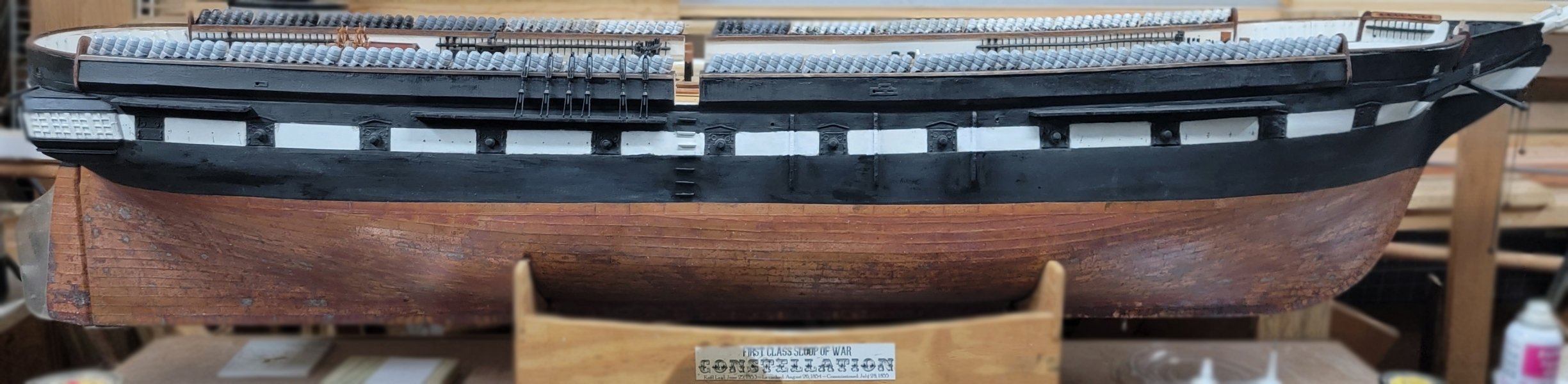
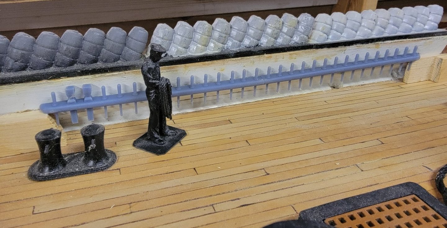
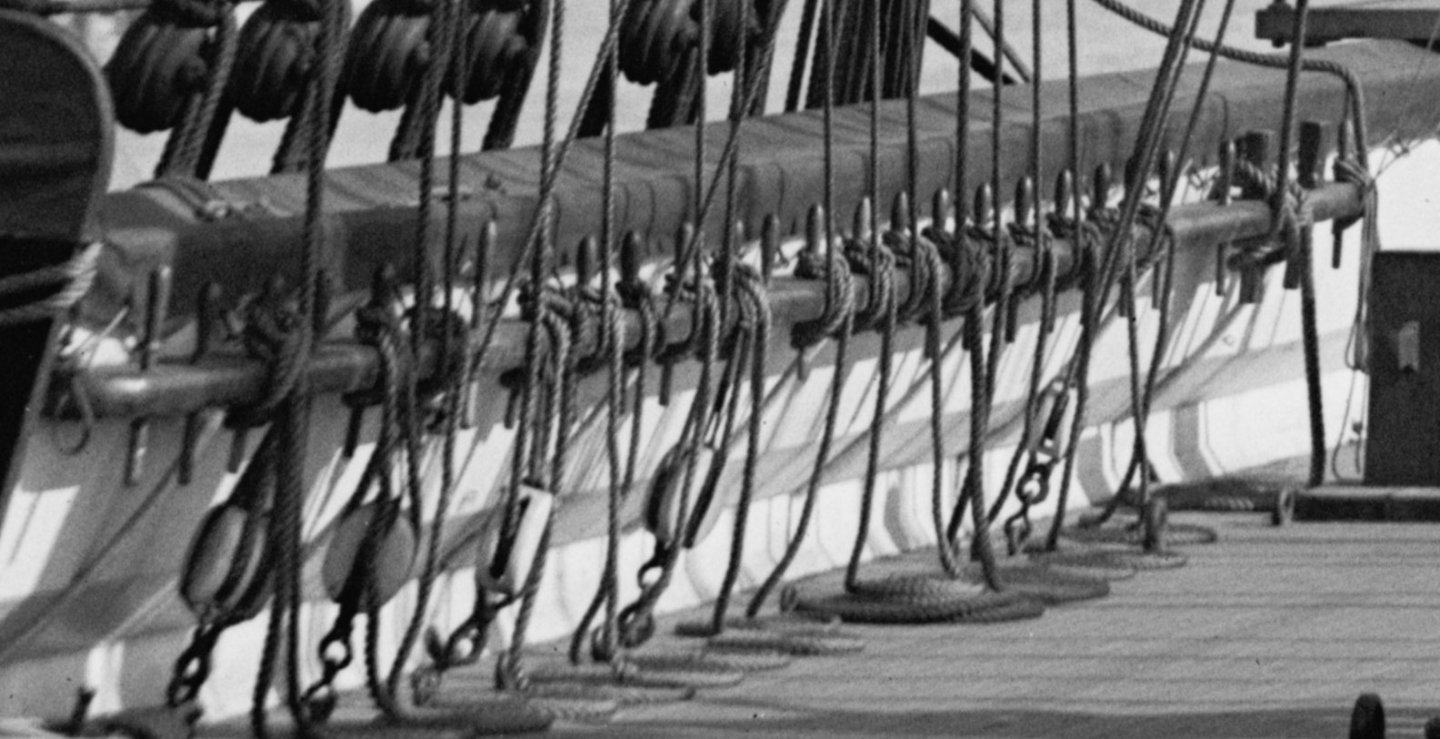
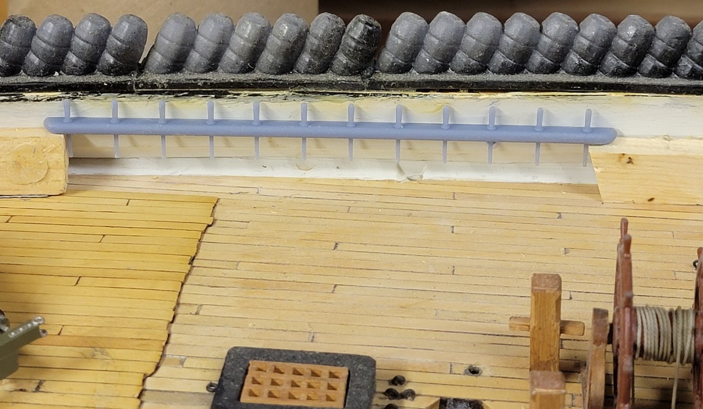
 The best image of the bow pin-rails is one from 1926 when the ship was in Newport Rhode Island These were modeled the same for each side, but the angle on the back was reversed because the bulwark leans outboard here. And her they sit where they eventually get installed
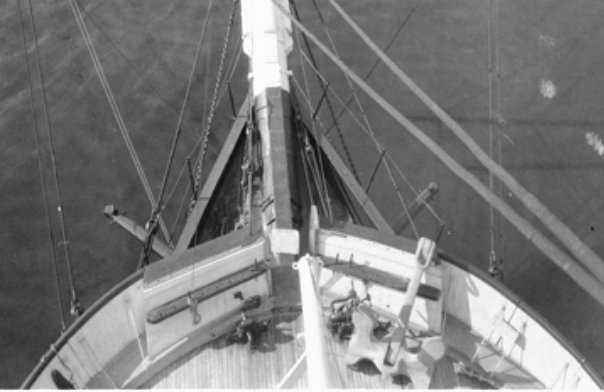
- 553 replies
-
- 5
-

-
- sloop of war
- constellation
- (and 3 more)
-
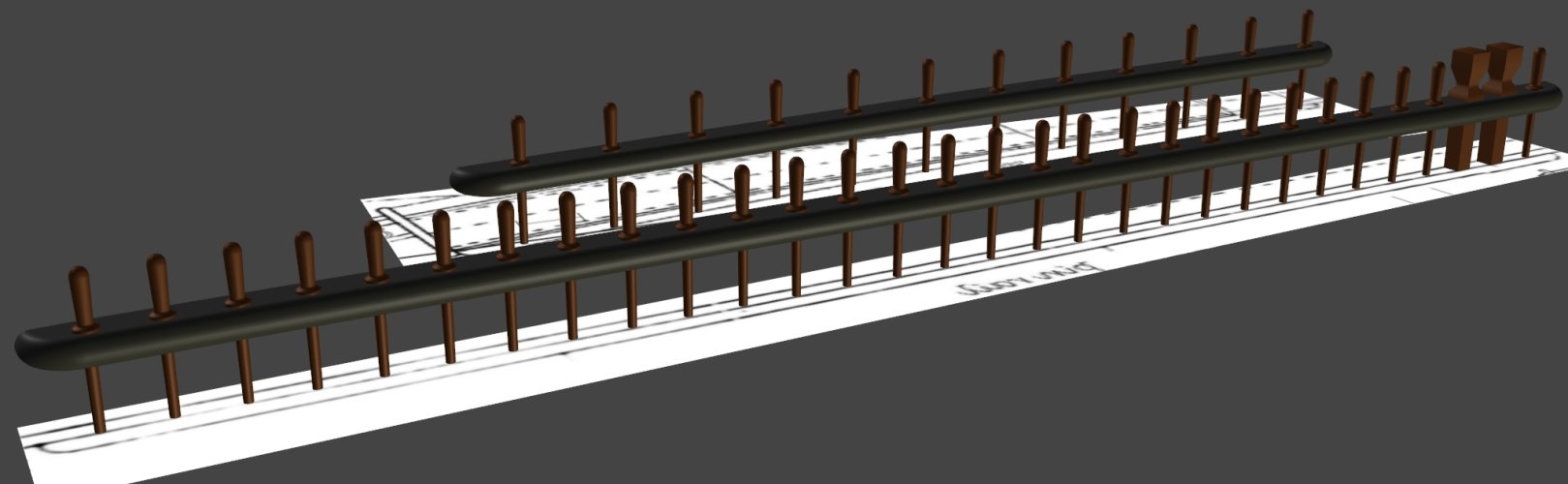
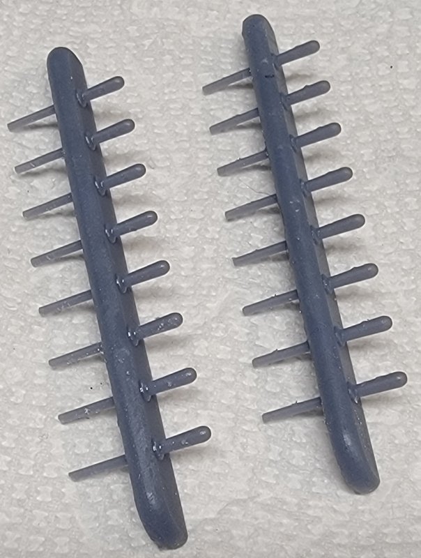
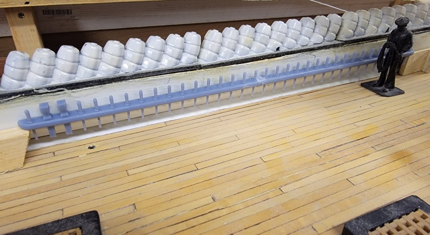
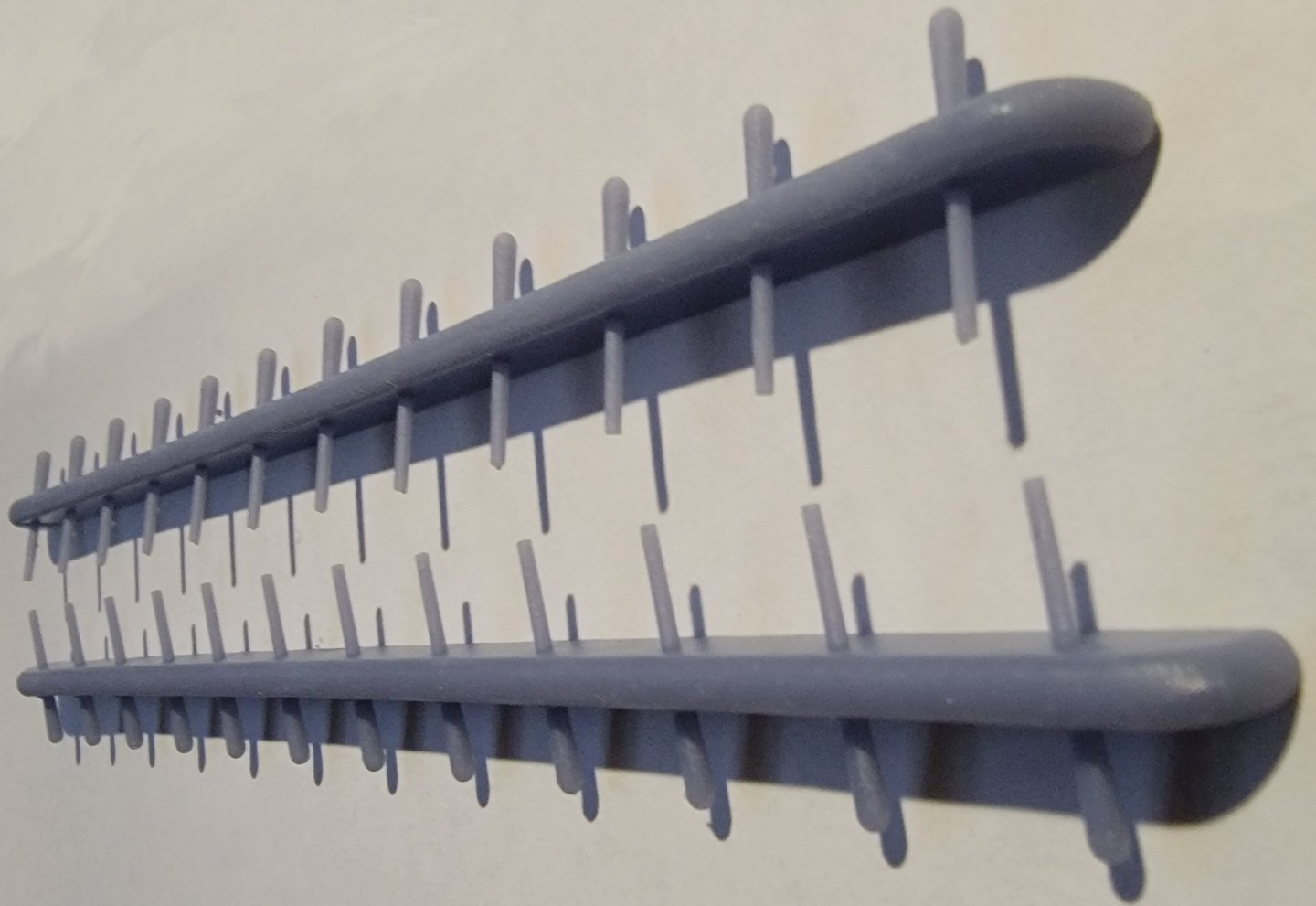
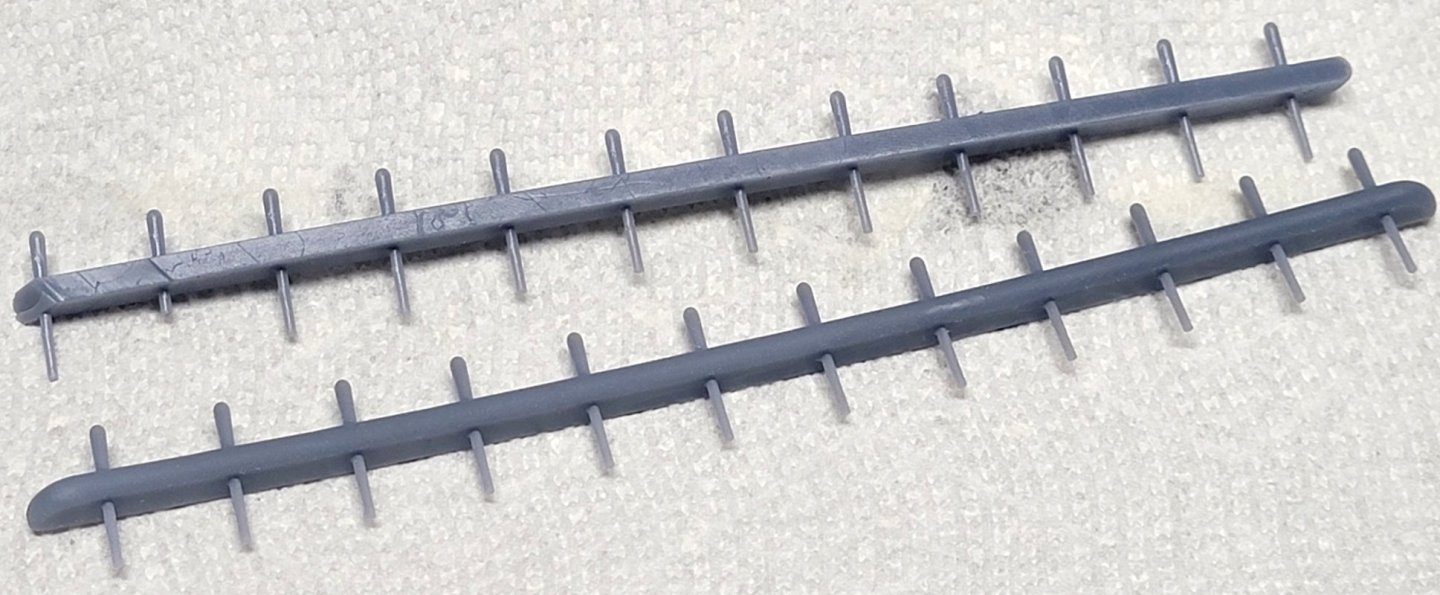
The midships pin-rail printed perfecly, and awaited the gloms of primer, paint, and clear-coat that will protect from UV while sailing in the Chesapeake Bay. The forward pin-rails are on the printer as I type this... And here's the forward pin-rail
- 553 replies
-
- 2
-
-
- sloop of war
- constellation
- (and 3 more)
-
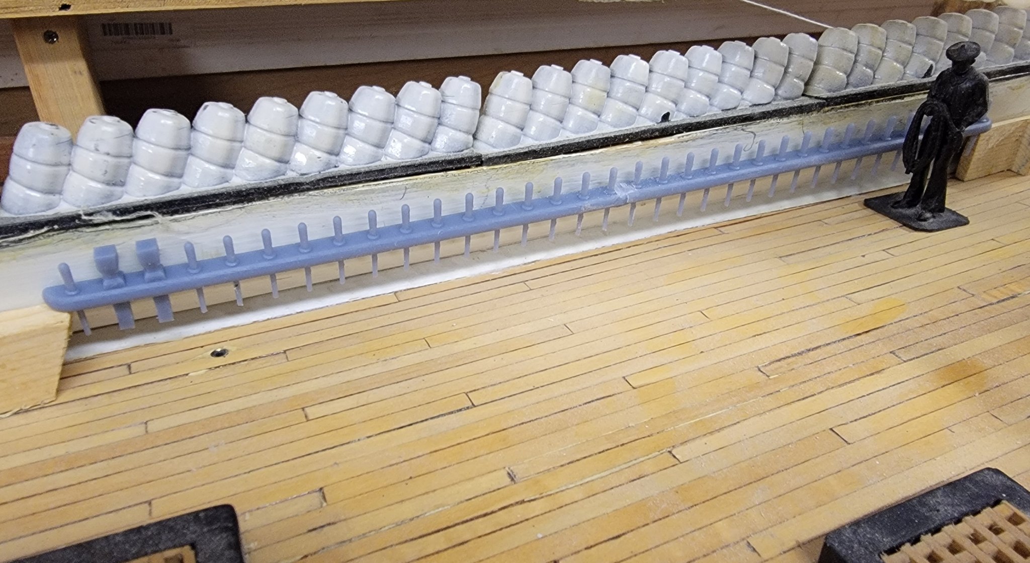
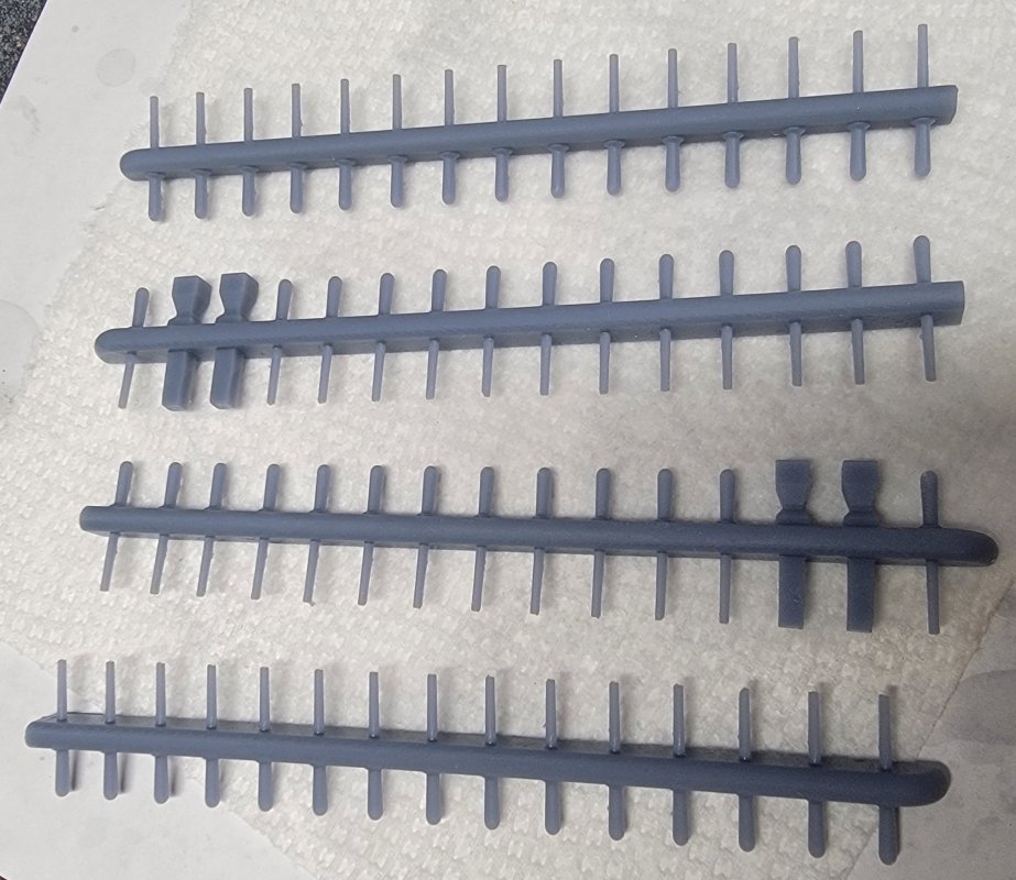
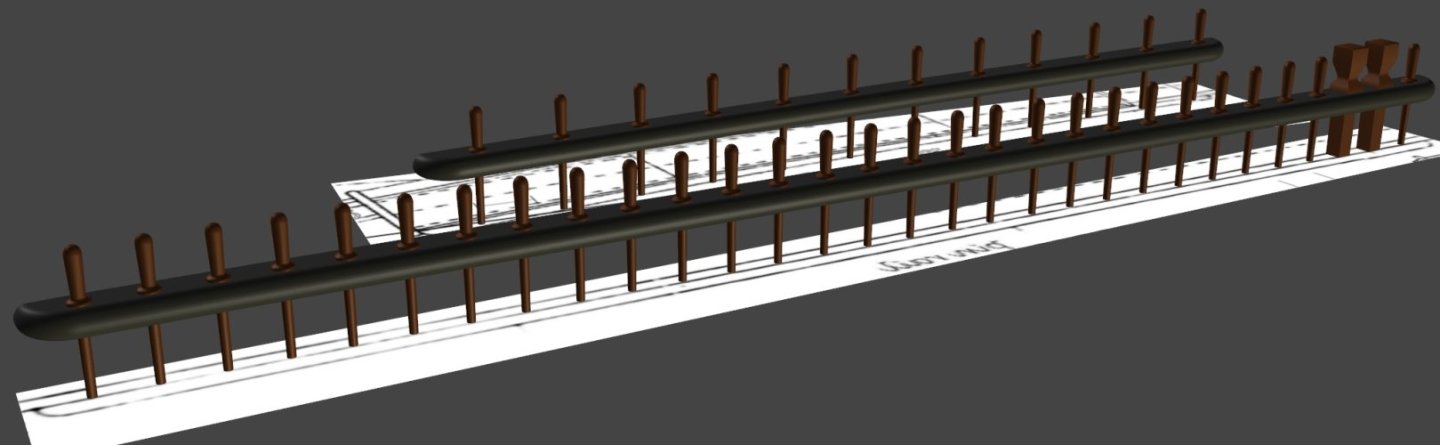
Half-an-hour-ish, and I've fFixed the pin-rail model to have the proper angle back-side, and set it to printing. Five hours and some change later it came out perfectly. See the angle? Well there it is siting somewhere near where it will live. While that was printing I started making the midships pin-rail; the one closest in this screen capture. In this picture from the 1890's, I originally though there was a caval at the aft end, but it actually appears to be a pair of meat tenderizers. This wasn't going to fit in the printer, even at an angle, so I made each side in two parts, and angled them (not to fit, but make them more likely to print properly) As I type here, this one is on the printer with about 4 hours to go Keeping with that workflow I should be making the forward pin-rails while the others print, but it's almost 3am, so, later...
- 553 replies
-
- 3
-
-
- sloop of war
- constellation
- (and 3 more)
-
There are no kits of the 1797 frigate Constellation available, never have been.
-
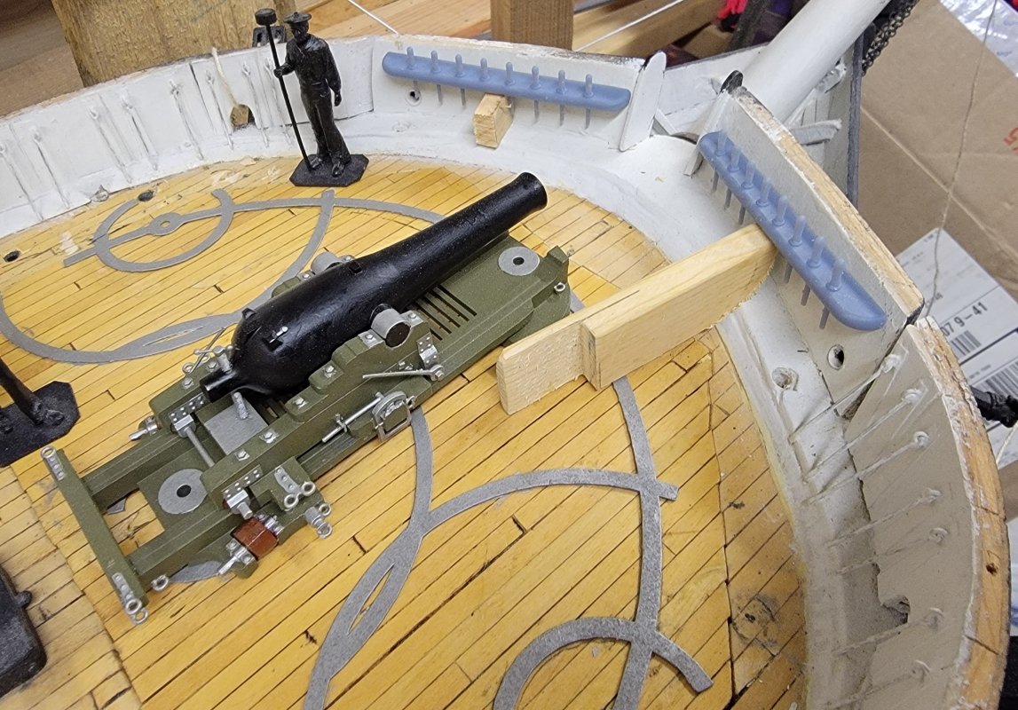
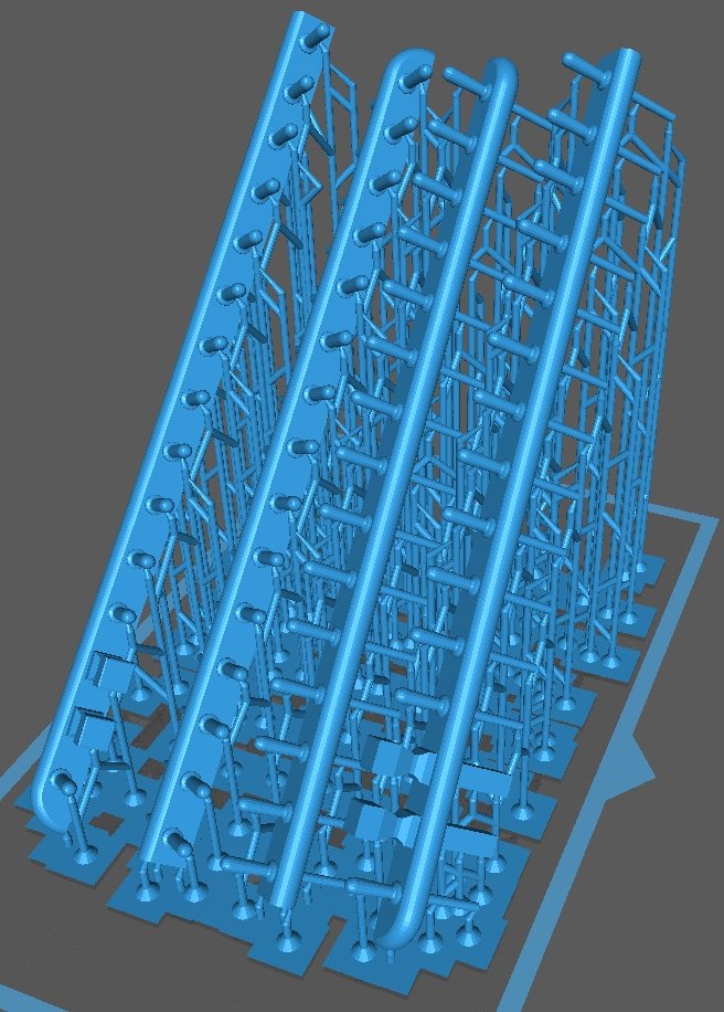
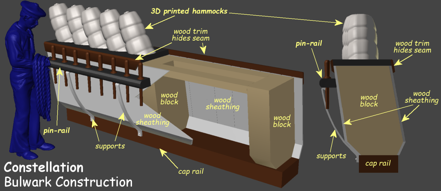
It's gotten too cold to pick up where I left off on Pride of Baltimore back in June, or even hang-out in the unheated shop for more than a few minutes; so I worked on 3D models for an item that's kind-of holding up starting on Constellation's rigging - pin-rails. Here' the first attempt at the aft-most rails, which printed pretty fairly, though the left end of the upper one, and one of it's pins didn't do so well. While that's repairable, when I modeled it, I forgot the bulwark it attaches to leans inboard a bit and forgot to model that angle on the back surface. Sanding that angle in would make the rail too narrow, so I'm fixing the 3D model and will reprint it. The rails will be pinned to the bulwark where the wood blocks are inside it. This pic shows how the bulwarks are constructed, as well as that inboard lean I mentioned.
- 553 replies
-
- 2
-
-
- sloop of war
- constellation
- (and 3 more)
-
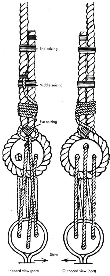
This help? The lanyard is hitched in the space between the bight of the shroud and the upper deadeye. That's what basically ties it off. the remaining is given a few wraps around the shroud, and the tail seized to it just to do something with the loose end. There's good chance of a lanyard breaking or being cut on a warship, and having that excess can save time in repair, not to mention the method of taking up tension on them requires a bit of length to set up. I'm sure Victory was kept very prim and proper, being an admiral was aboard At least you didn't do this...
-
What's wrong with Artesania Latina Constellation?
JerryTodd replied to Antti's topic in Wood ship model kits
So happy to hear AL is no longer producing that pile of words the admins would probably ban me for. Constellation was the largest purpose-built sailing sloop-of-war the Navy built. I've seen it claimed her design was inspired by the performance of the Cumberland after that ship was razeed. Decatur was a much smaller ship; 556 tons to Constellation's 1400 tons so the scale using that kit to start from is way off. Since Decatur is so much small, you might be able to use the AL kit for materials, and cut the proper bulkheads from the kit's - basically build from scratch using the kit's materials. -
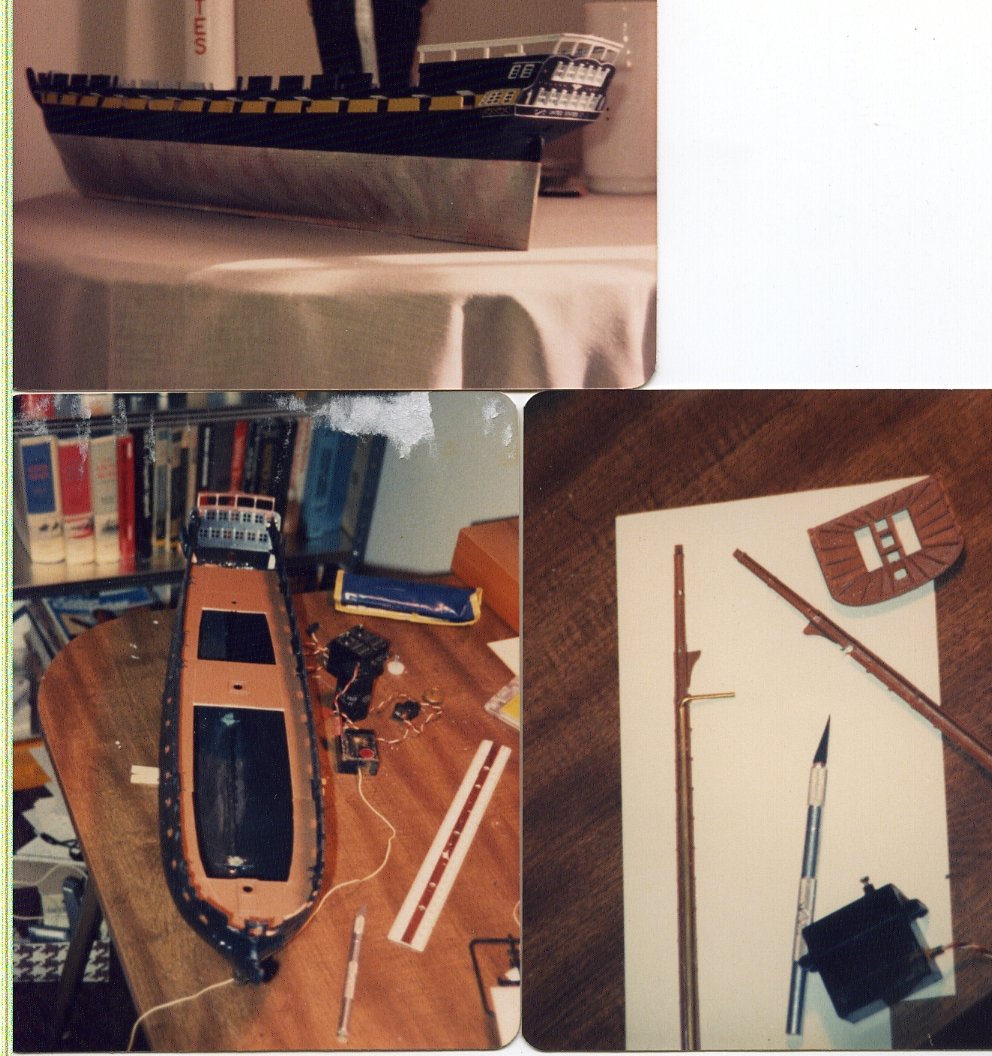
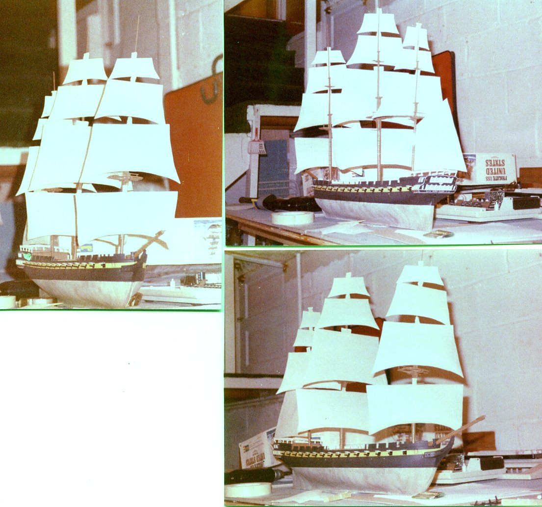
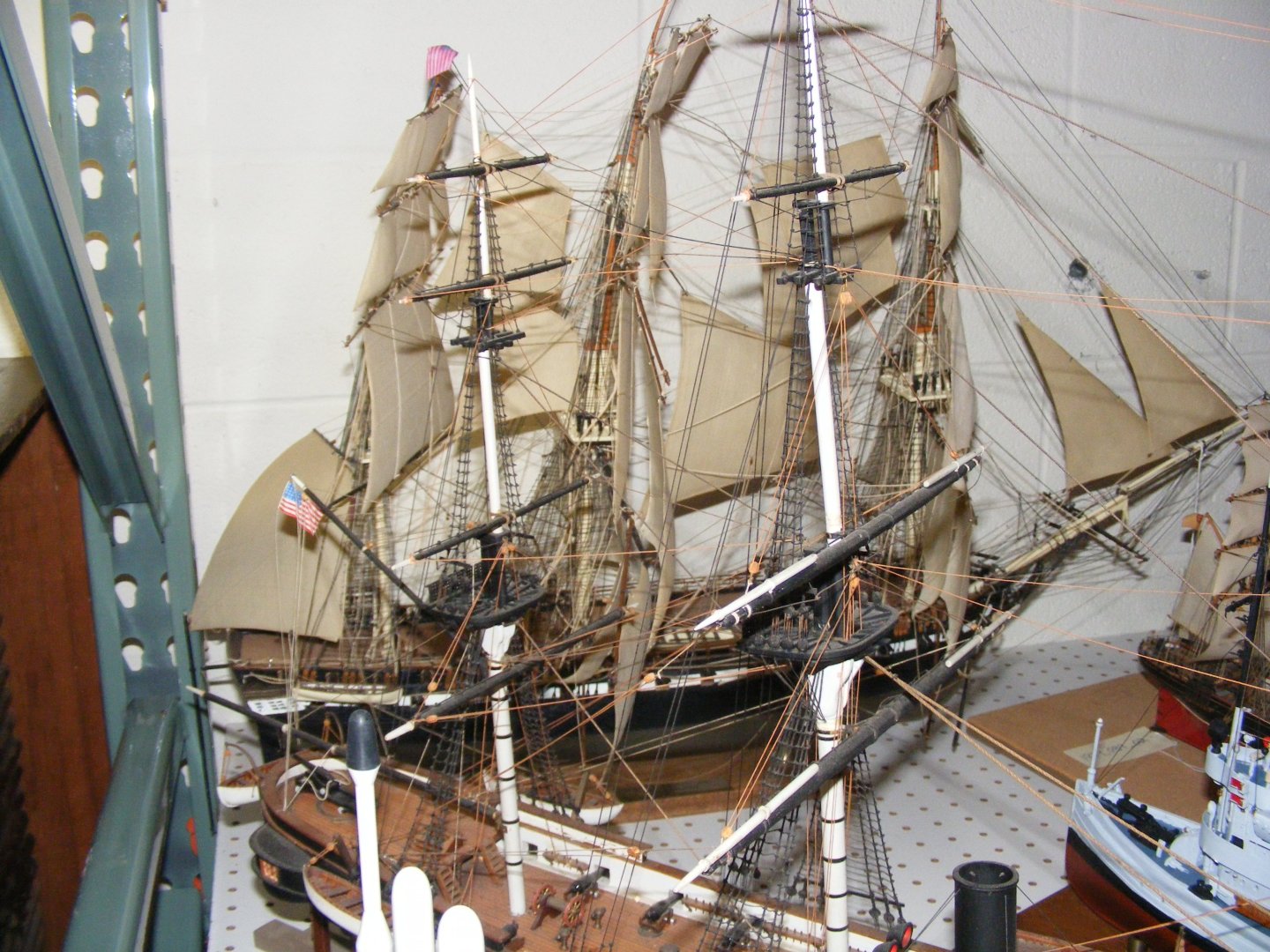
I've built several Revel 1:96 scale Constitution/United States kits, most of them modified for RC sailing. The lower masts, topmasts, and lower yards are mostly hollow and made in two halves. I would always put a wood rod, usually from a bamboo skewer or chopstick, and fill it with epoxy putty (plumber's epoxy). Solid plastic spars I would replace outright with wood, and the real thin ones, like the mizzen t'gallant mast, with brass rod and plumber's epoxy to shape parts, like the heel and truck, etc. Sorry, I can't seem to find any pictures of the mentioned models except for these, which don't show what I'm referring too very well. This was the last such kit I completed for RC which used a bell-crank sort of set-up in the hollow lower mast to turn the course-yards, which is why all the spars had to be stronger than the kit's plastic spars could manage. When I volunteered at the Naval Academy Museum shop in Preble Hall, I got to see the store rooms where the stuff not on display in the museum was kept, which contained a lot of these kits built by alumni and donated to the museum. Pretty much all of their plastic spars had warped, curled, and deformed, just sitting on a shelf in a environmentally controlled storeroom. The cotton thread rigging had also rotted away on most of them as well. Here's one of many, tucked behind some other models on a shelf.
-
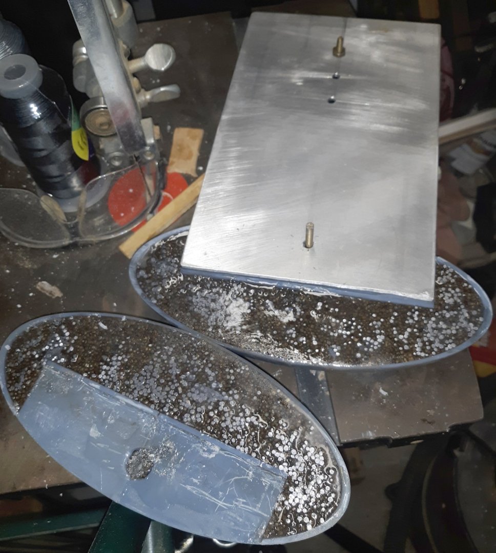
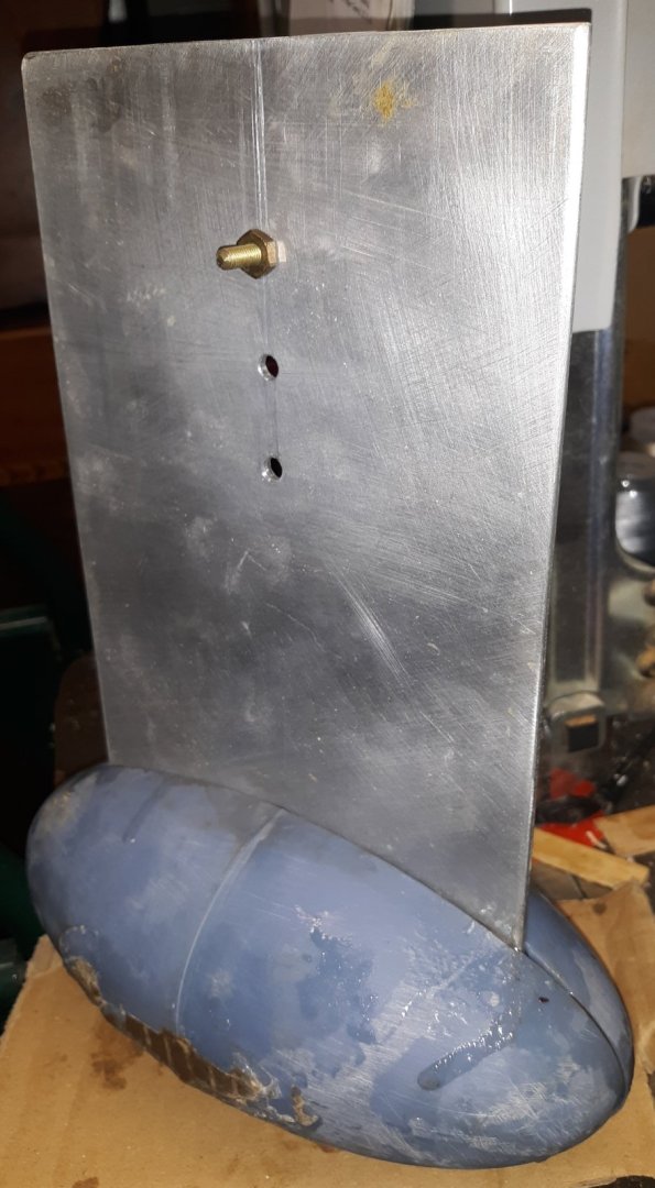
Winter, as handling epoxy in an unheated garage matters, seemed to last almost till the end of April. But finally the temperatures and my time have coincided enough that I may finally get this ostrich egg finished. It seems the plastic egg deformed a little from the weight, so the two halves don't lay flat to each other. If I do this again, and for you folks thinking of using this method, I will put ribs inside the bulb to stiffen it, and fashion some sort of cradle to sit on that supports it so the bulb doesn't try to flatten out as the epoxy and lead set-up. There were also pockets in the bulb that resin hadn't gotten to and I could hear the shot rattling around inside. If there's a next time, I'll mix shot and resin separately and pour the mix into the bulb. What sounded like the biggest of these pockets was behind the flange? I modeled in for the plate to slide into. I opened the holes here to pour more resin in and hopefully fill this void. I re-drilled to holes for the pin that will keep the bulb from sliding off the plate, and cut about a 3 inch length of 3/16" brass rod for the pin. I mixed very fine sawdust from my band-saw with the epoxy to make a paste of it, and buttered both sides of the bulb, placed the pin, and plate, and put the other half on. I used a sliver of wood as a wedge in the bottom seam to push the seam on top, where the plate enters, as closed as I could, making something of a gap at the bottom. The epoxy butter filled this in fairly well, but the seam's open almost all the way around, which I'll fill with more epoxy butter. The bulb also needs some clean-up from epoxy runs and cardboard that stuck to it; and I intend to wrap it in glass cloth as that'll be stronger than the resin alone if the boat should hit a rock or something.
- 79 replies
-
- 3
-
-
- pride of baltimore
- privateer
- (and 3 more)
-
3D Naval Guns 1850s ~ 1870s
JerryTodd replied to JerryTodd's topic in CAD and 3D Modelling/Drafting Plans with Software
Someone over in Deven, England needed a pair of 2-banded Brooke rifls for a 1:48 scale model of the Confederate ironclad Neuse. I hadn't printed either of the Brookes as yet, so I soon discovered some bits were missing, ie, I forgot to mirror a part to the other side of the gun, actually, just the slide. I fixed the STL on Thingiverse, but to fix the already printed models, I printed that part and a couple of eye-bolts separately, attached them to the models with resin zapped with UV light. They're carefully packed and off to England, making me an International Arms Dealer It's very expensive shipping a 95 gram box to the UK from the US, over $30 USD in fact, but he was adamant there was no one local to 3D print them for him.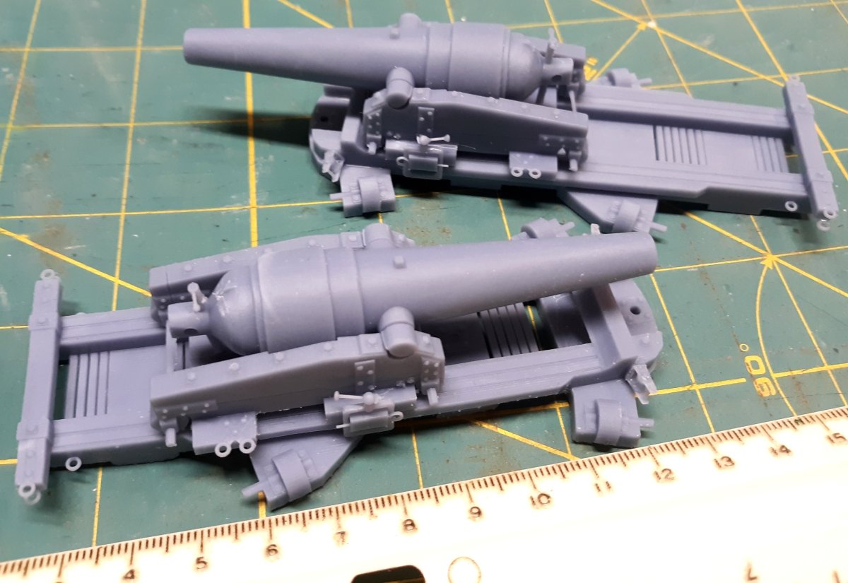
-
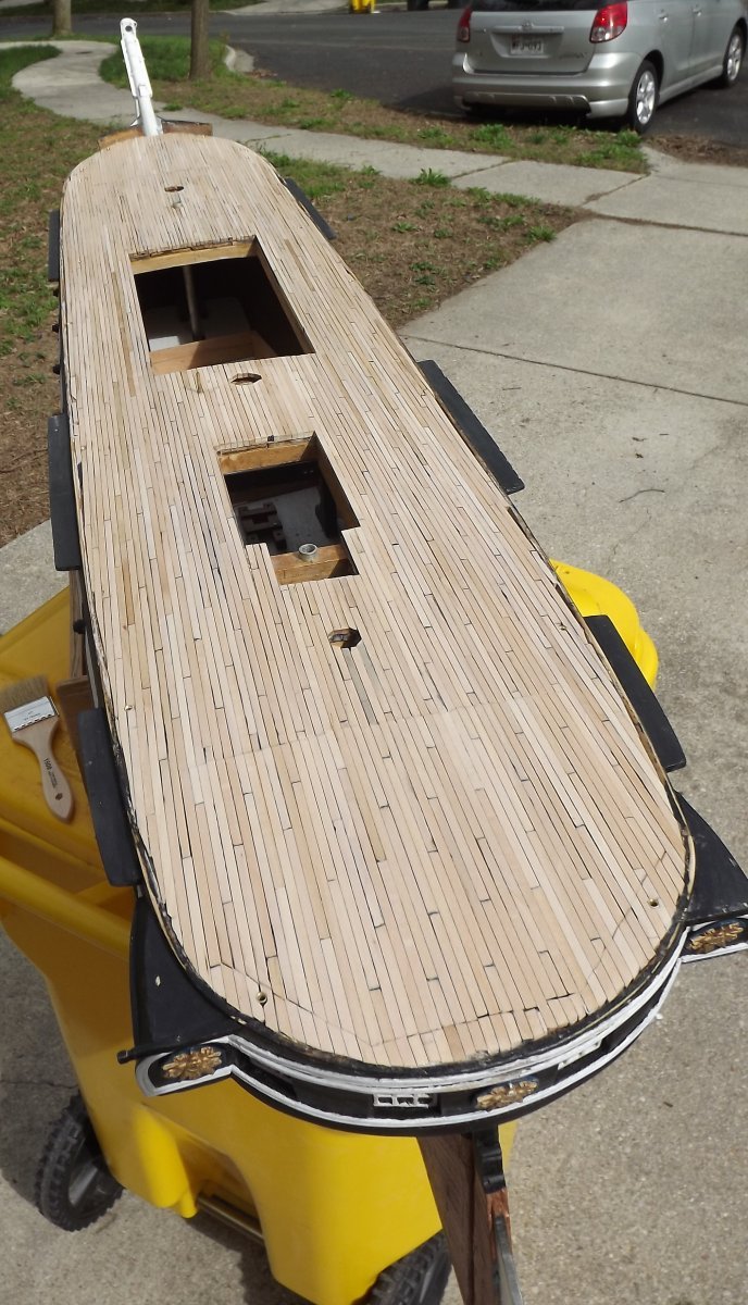
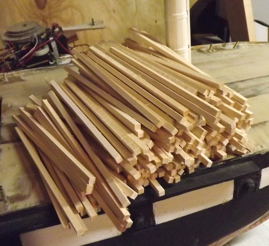
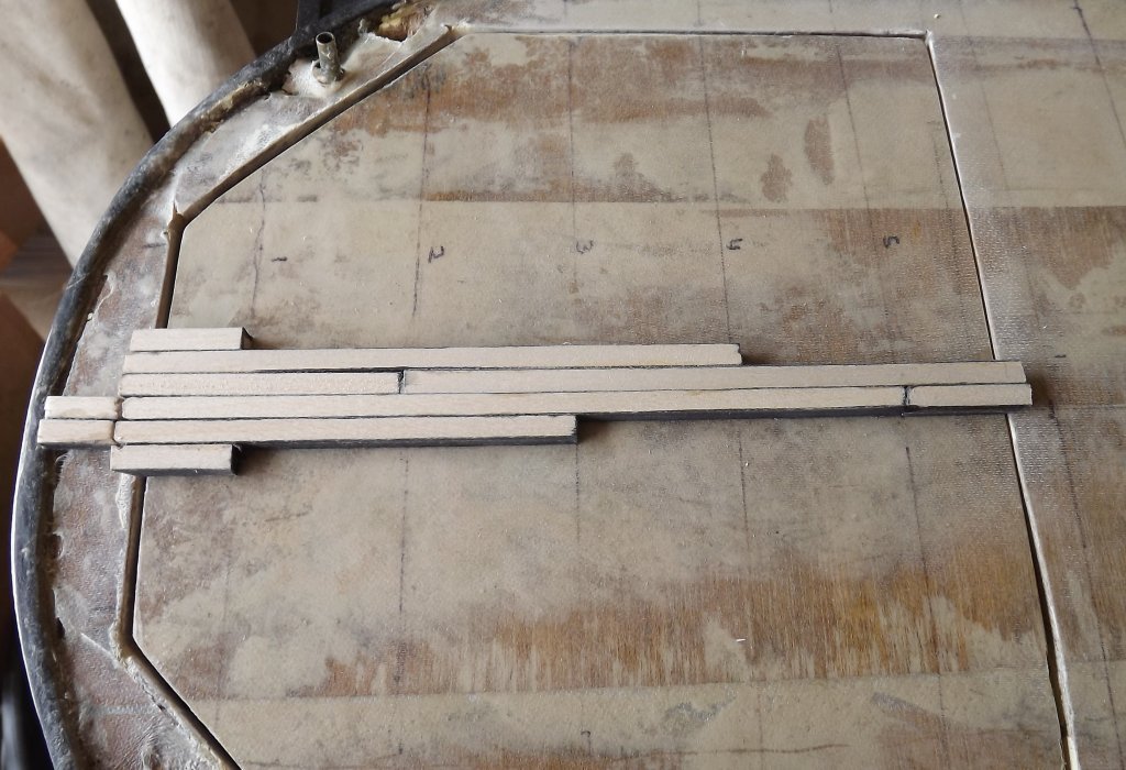
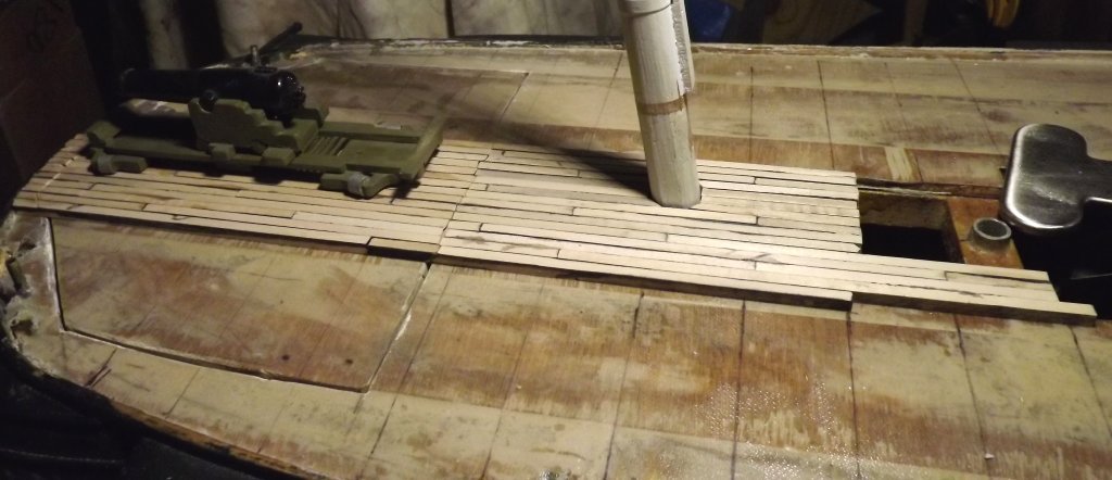
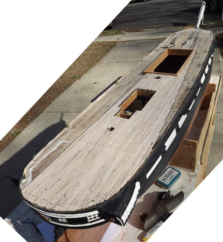
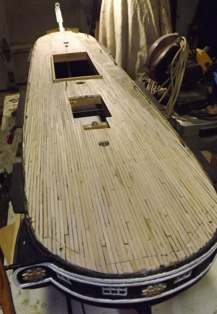
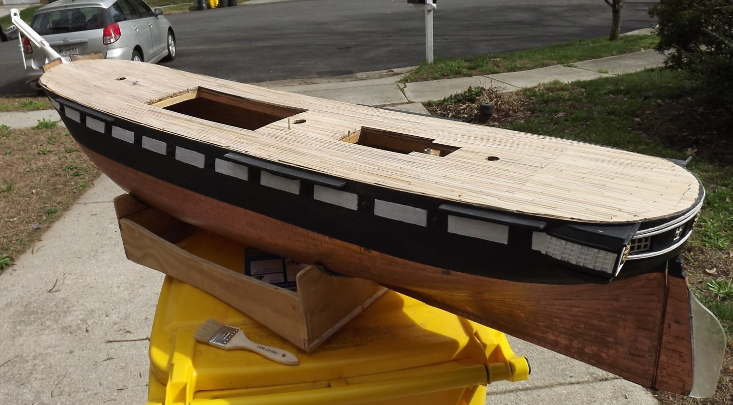
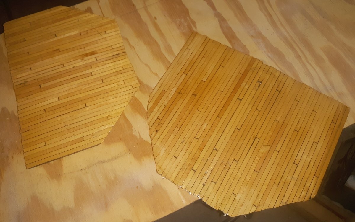
Do you just want it done so you can move on? Is there a deadline? Cutting corners may get you somewhere faster, but it tends to magnify errors, not just in looks, but in frequency. I glued all 500ish piece of scale-length decking (cut from 4 foot lengths) on my 5 foot long hull when I easily could have scribed some plywood. There were a couple of places I had to pull a piece off and put in another, reusing the removed piece somewhere else. That would have been a bigger pain using full 4 foot lengths. When it was done, none of the left-over scrap was longer than an inch, so doing it this way was a more efficient use of materials. I recommend all planking/plating be done in scale pieces on anything 1:64 scale and up, because you get more from it that way. The decision,of course, is only yours to make.

-
USS only applies to COMMISSIONED Naval Vessels of the United States and wasn't officially used until Executive Order 549 in 1907
-
3D Naval Guns 1850s ~ 1870s
JerryTodd replied to JerryTodd's topic in CAD and 3D Modelling/Drafting Plans with Software
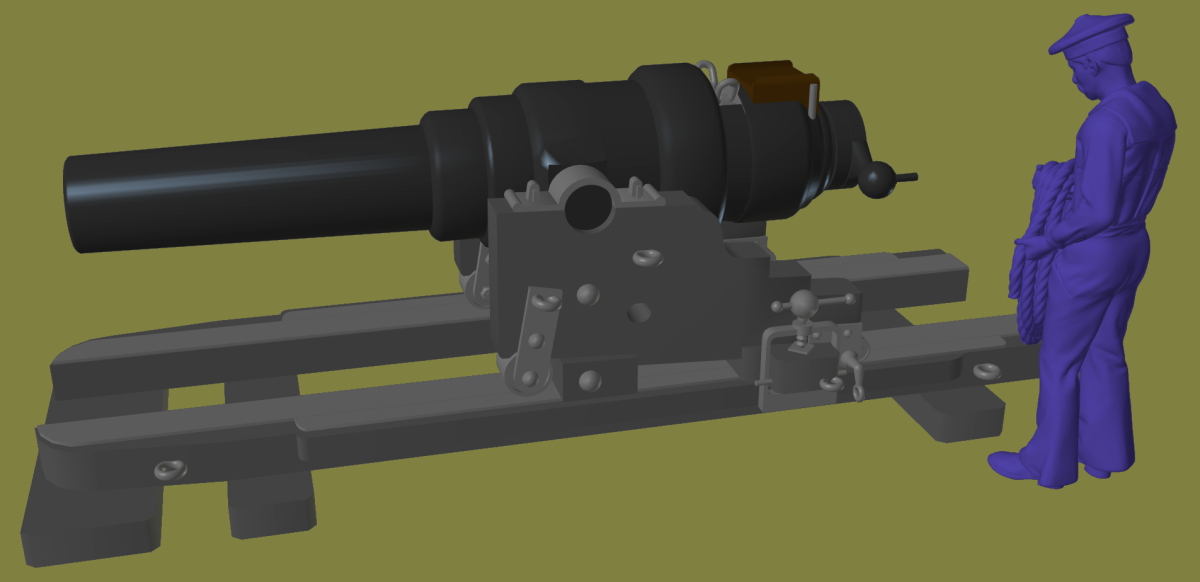
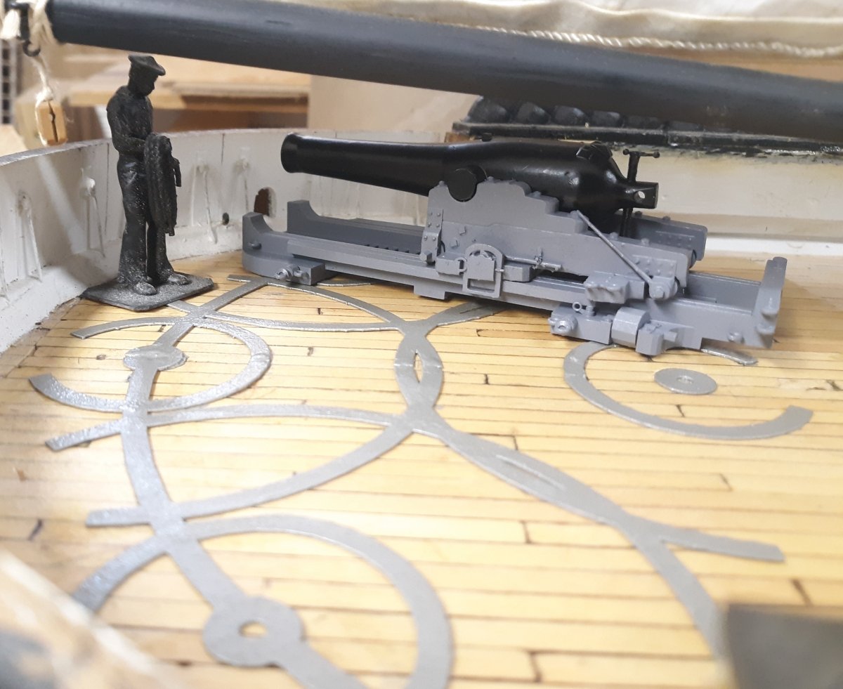
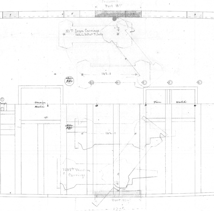
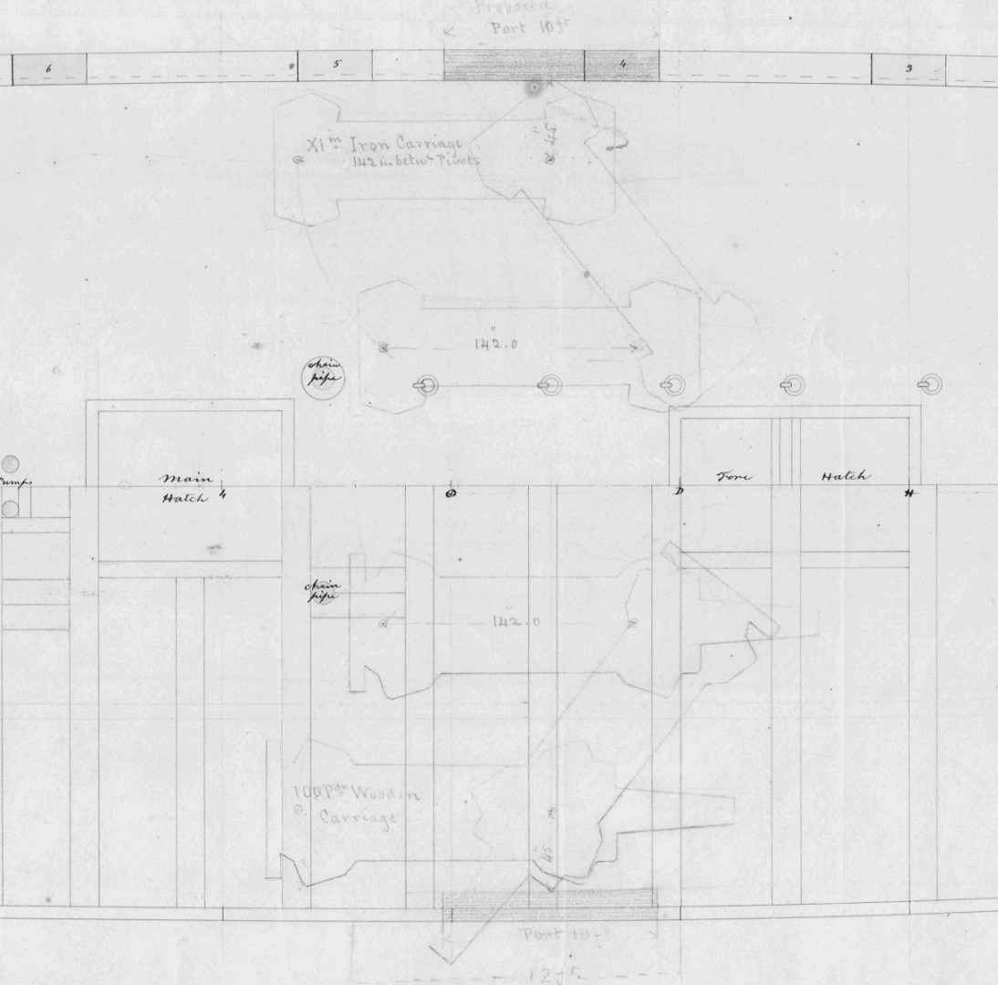
I was going to make a Marsilly type carriage for the 110# Armstrong rifle, but found this drawing on the NMM site, which is basically the Warrior's pivots, so went with that. So far this is what I have In the mean-time, the XI inch Dahlgren on the iron pivot carriage is looking like this... As mentioned, Constellation, as a training ship in the 1870's, was armed with the XI Dahlgren, and a 100# Parrott rifle on a wooden carriage on her gun-deck, with the corresponding gunports widened to 10 feet. here's something to compare the two...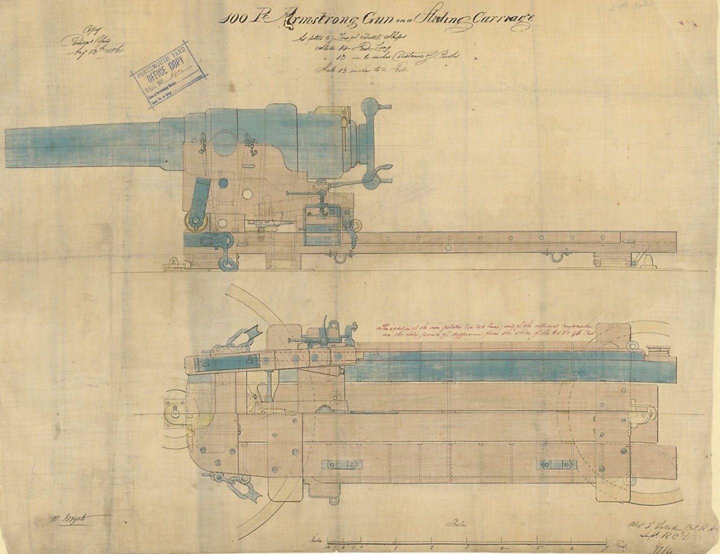
-
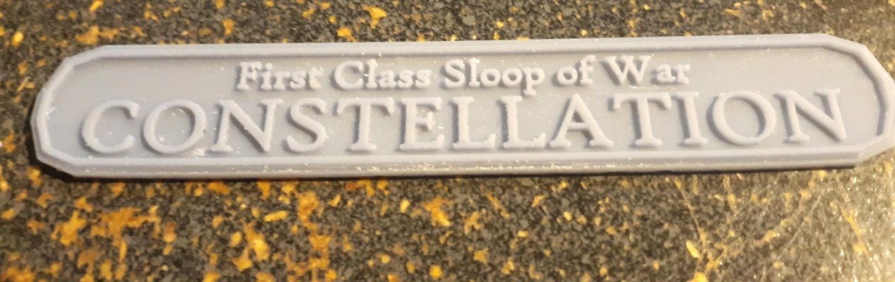
I think we all go through a "name plate phase" as we grow in our modeling I have to say, you're making the best use of what I consider to be a criminally awful kit, that I've seen yet. I wonder if it would have been cheaper for you to buy materials and build from scratch.
-
3D Naval Guns 1850s ~ 1870s
JerryTodd replied to JerryTodd's topic in CAD and 3D Modelling/Drafting Plans with Software
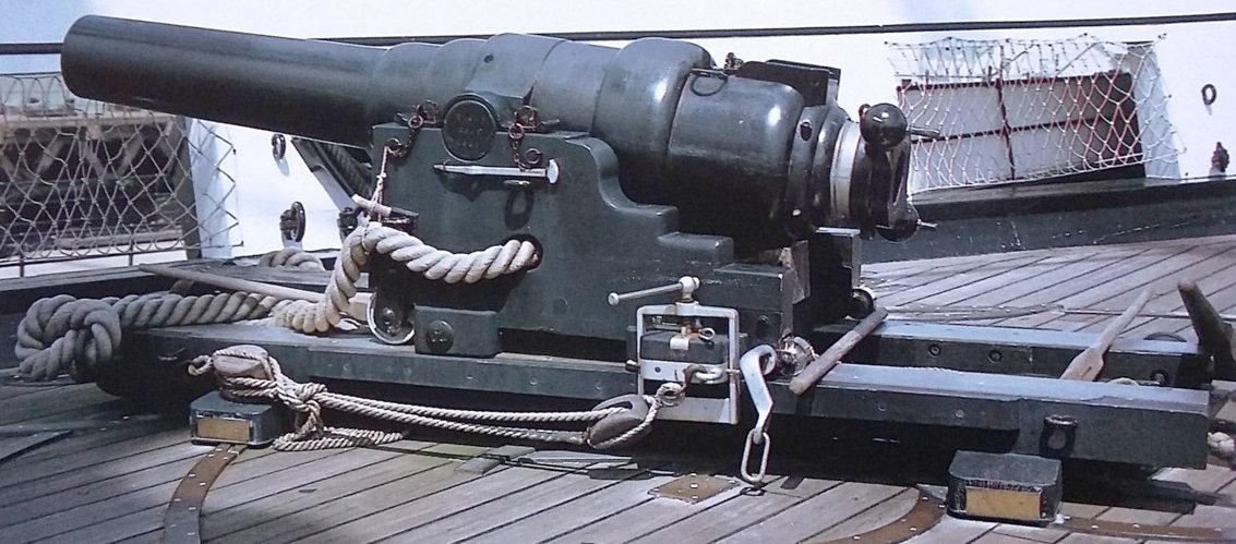
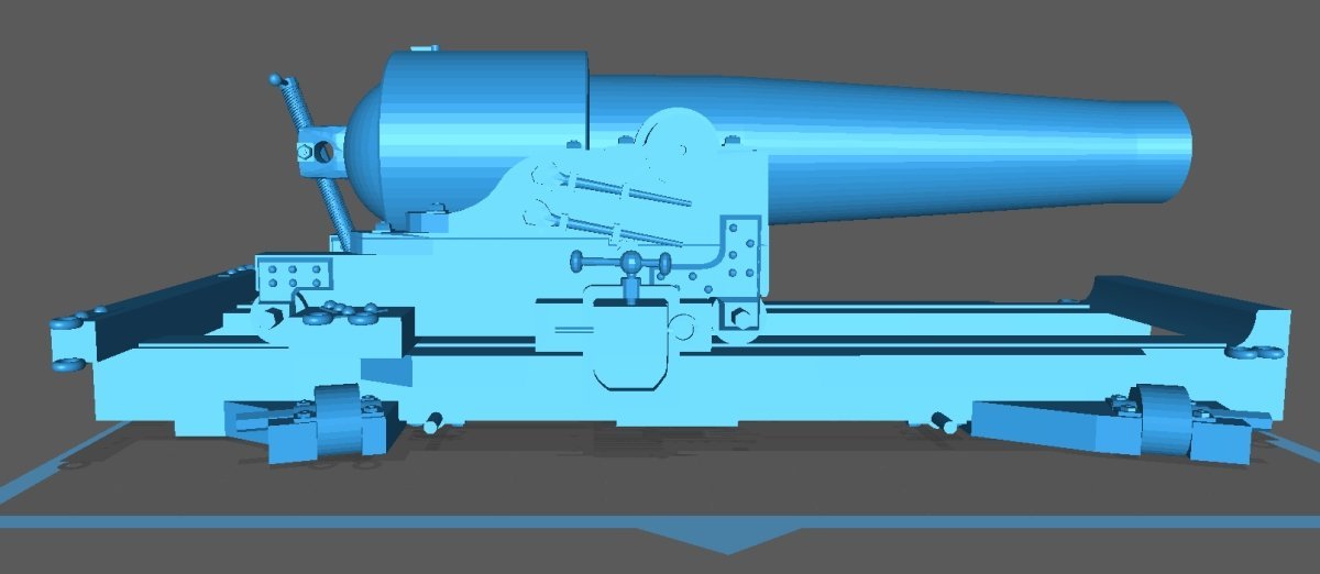
The X inch Dahlgren's and the deck tracks for them are practically done, but that's in my Constellation log. The next WIP is the XI inch on an iron pivot. I've found many images of iron carriages, but all of them are from the 1880's and 1890's when some new technology had been applied, and I'm doing an 1870's version that's basically a war-time wood carriage done in iron. The drawing posted earlier is what I'm working from, but the person that drew it did it as an illustration for a sci-fi story, so I can't be sure of it's authenticity. At any rate, I'm picking a way at it.... Next up I think I'll do Dalhgren's rifle from this image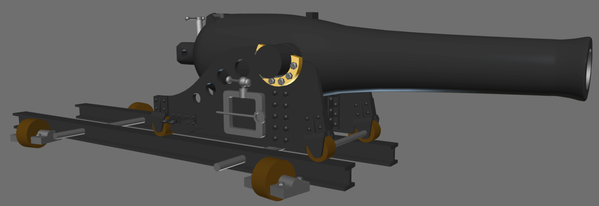
-
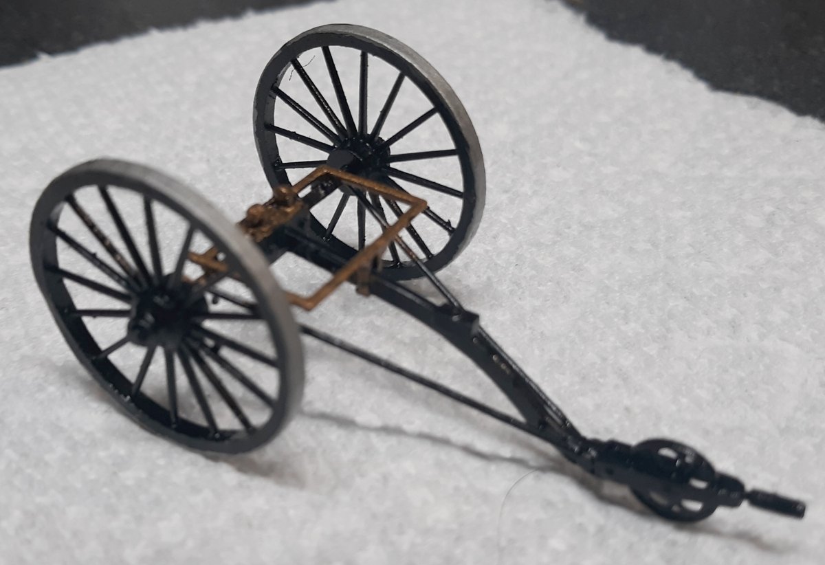
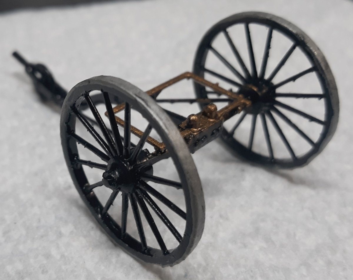
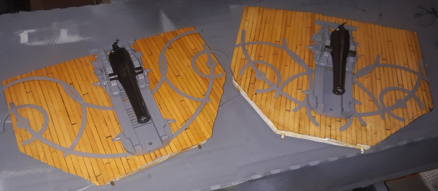
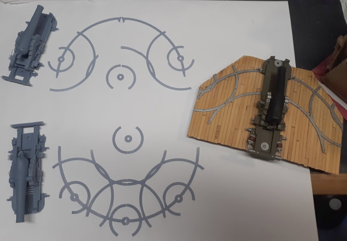
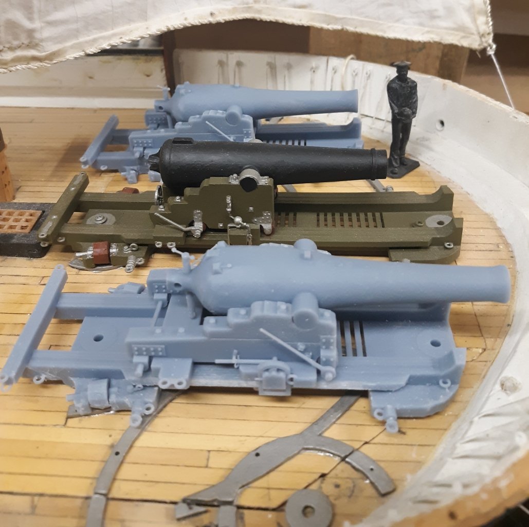
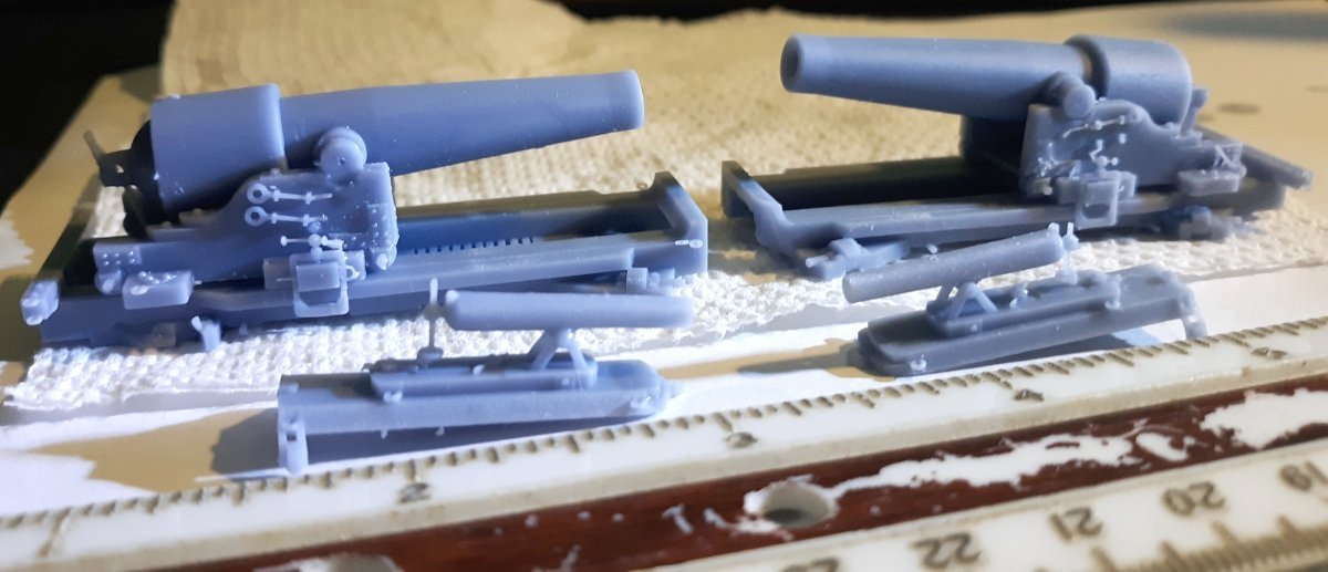
April 8th: The new pivot gun tracks were primed, painted, glued down (had to order a bottle of CA), painted some more. The guns barrels are painted, detailed, and clear-coated (no pic of that yet). The carriages are primed, but not painted yet. They'll be painted olive like the previous set of gun carriages. The new field carriage for the boat-howitzer also got painted, and after some clear-coat, will go to it's home in the stern-sheets of the launch. (sorry for the poor images)
- 553 replies
-
- 4
-
-
- sloop of war
- constellation
- (and 3 more)
-
3D Naval Guns 1850s ~ 1870s
JerryTodd replied to JerryTodd's topic in CAD and 3D Modelling/Drafting Plans with Software
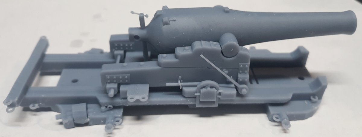
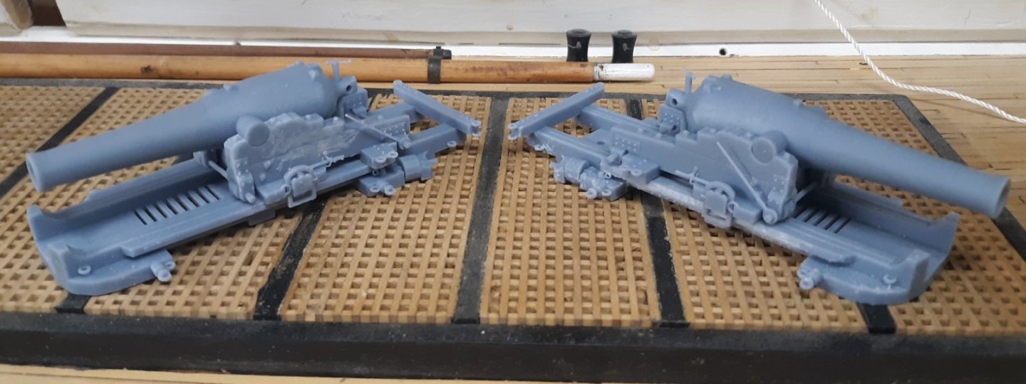
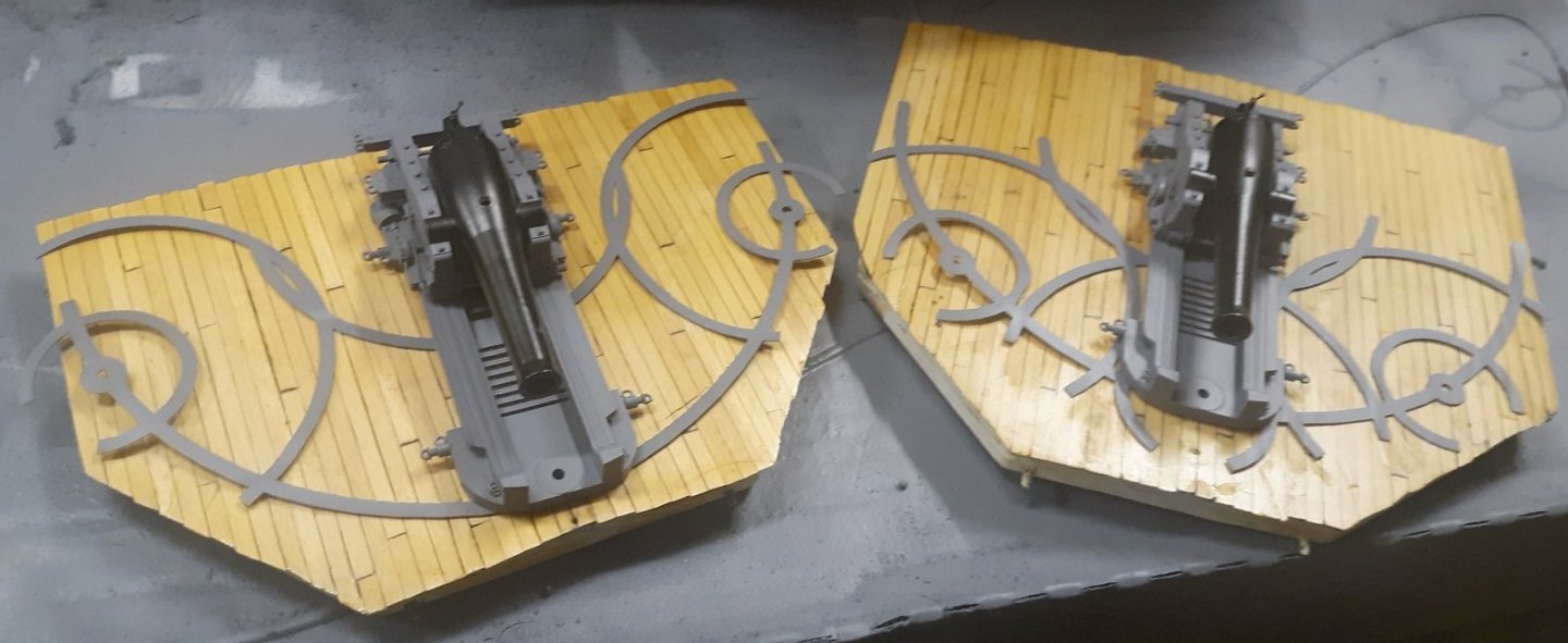
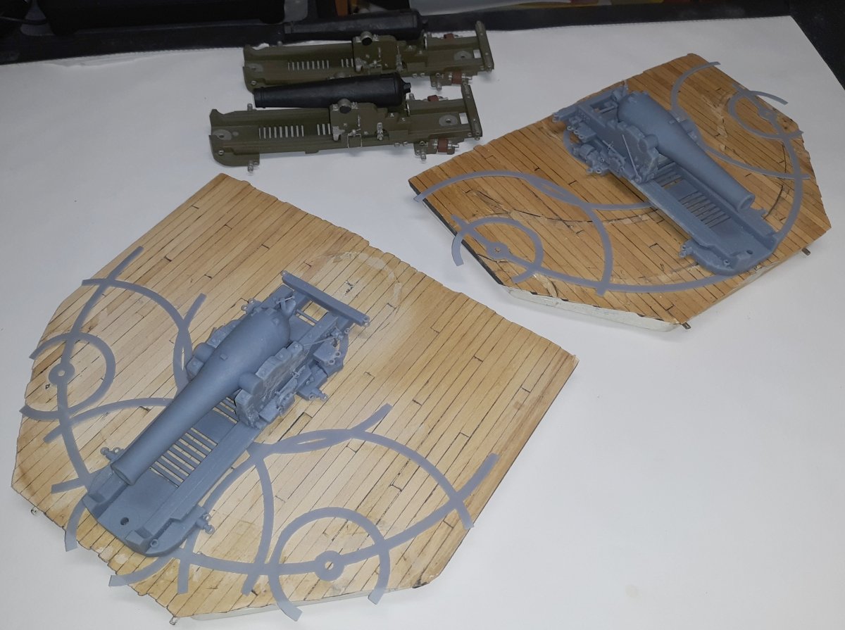
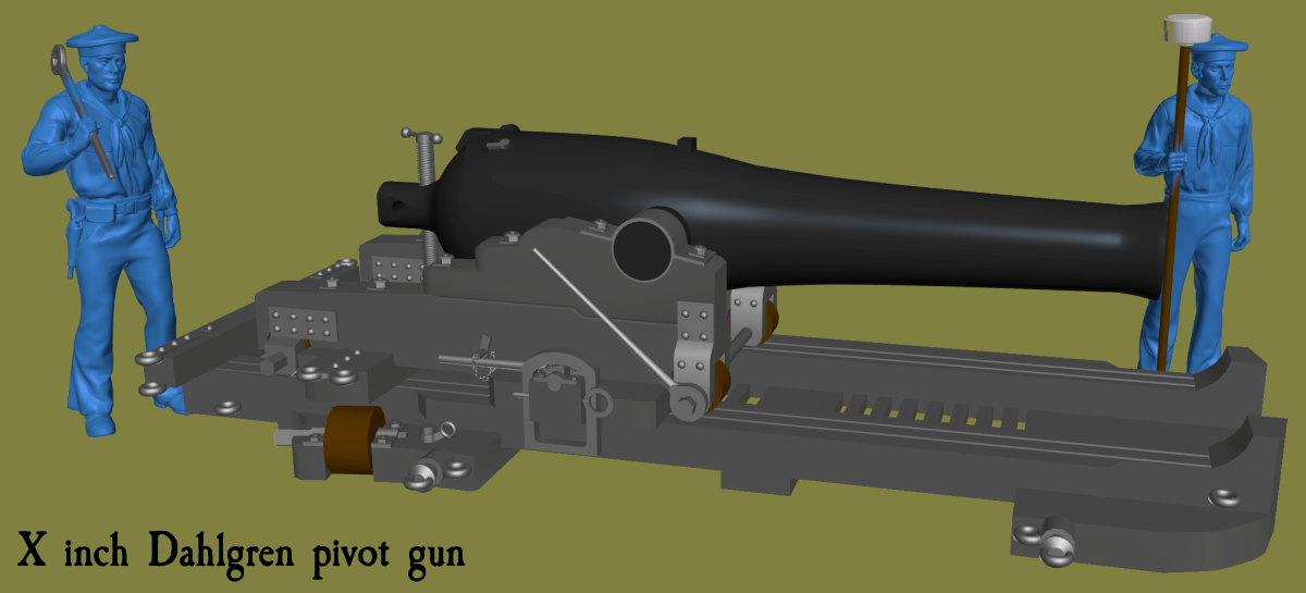
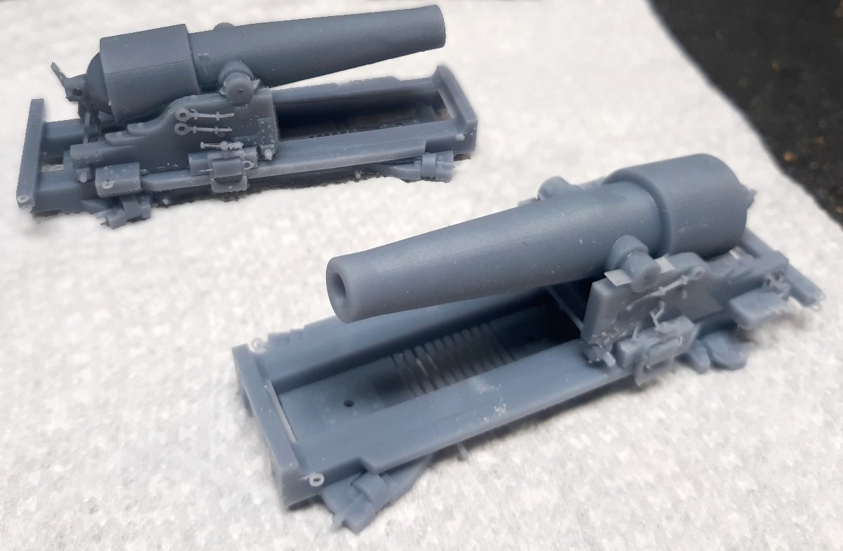
Since I'm replacing the Constellation's pivot guns with this X inch Dahlgren, need to print three of them; 2 for the model, and one for the sampler of Constellation's guns. Here's the second gun fresh off the printer. The first one lost a roller, but that can be fixed. The slide on these gun are shorter than the previous gun's slides, so new deck tracks had to be made to fit. The third gun hasn't been printed yet. The pair sitting on the model's main hatch. The old tracks removed, the access hatches sanded, and refinished with the primed guns and tracks sitting in place.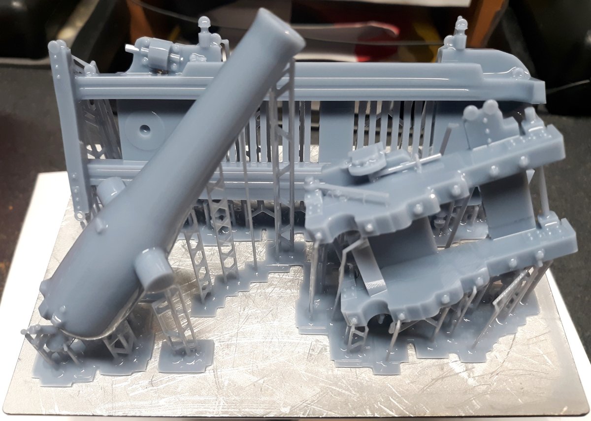
-
Why do the lower dead-eye strops and chains look like rope or cable? They should be iron
- 107 replies
-
- 1
-
-
- Frigate
- Confederacy
- (and 1 more)
-
It's all just sitting there, nothing's glued down yet, until it's actually painted. A pic with, and without flash. I need to watch those white-balance videos someone posted here at MSW.

- 553 replies
-
- 3
-
-
- sloop of war
- constellation
- (and 3 more)
-
The slides for the new guns are shorter than what was on the model, so new tracks had to be modeled, printed, and reprinted a little. The old tracks had to be removed and the scars sanded off the deck. Then the finish reapplied. Meantime the guns and tracks were primed.
- 553 replies
-
- 4
-
-
- sloop of war
- constellation
- (and 3 more)
-
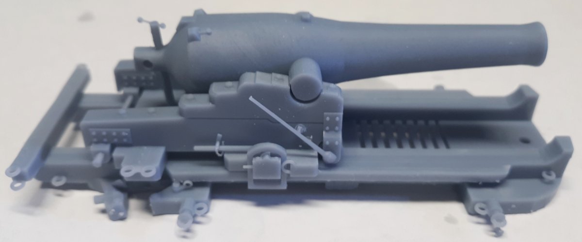
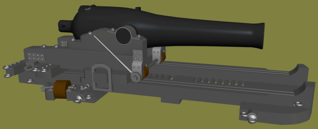
I finished the 10 inch Dahlgren. I didn't model the gun's breech as it was in Dahlgrens drawing. It looked like he left the breech of the Columbiad from the Traverse Carriage drawing and made the rest of it look like his 10" gun. I know Rodman guns were made with that sort of breech, but I can't find drawings of a Dahlgren like that. Dahlgren's patent drawings don't show that sort of breech either. The slide, while just like the one in the Mississippi plan, is shorter and wider; this will mean reworking the deck tracks on Constellation; but It also means it'll fits the space better, with more room for moving the gun about, as well as fitting on my hatches better. The print came out great except for one wheel on the back-left of the slide. I can replace that, and fix the pallet around it easily enough, so it's not a "failed print." The second gun printed better, it didn't lose any wheels
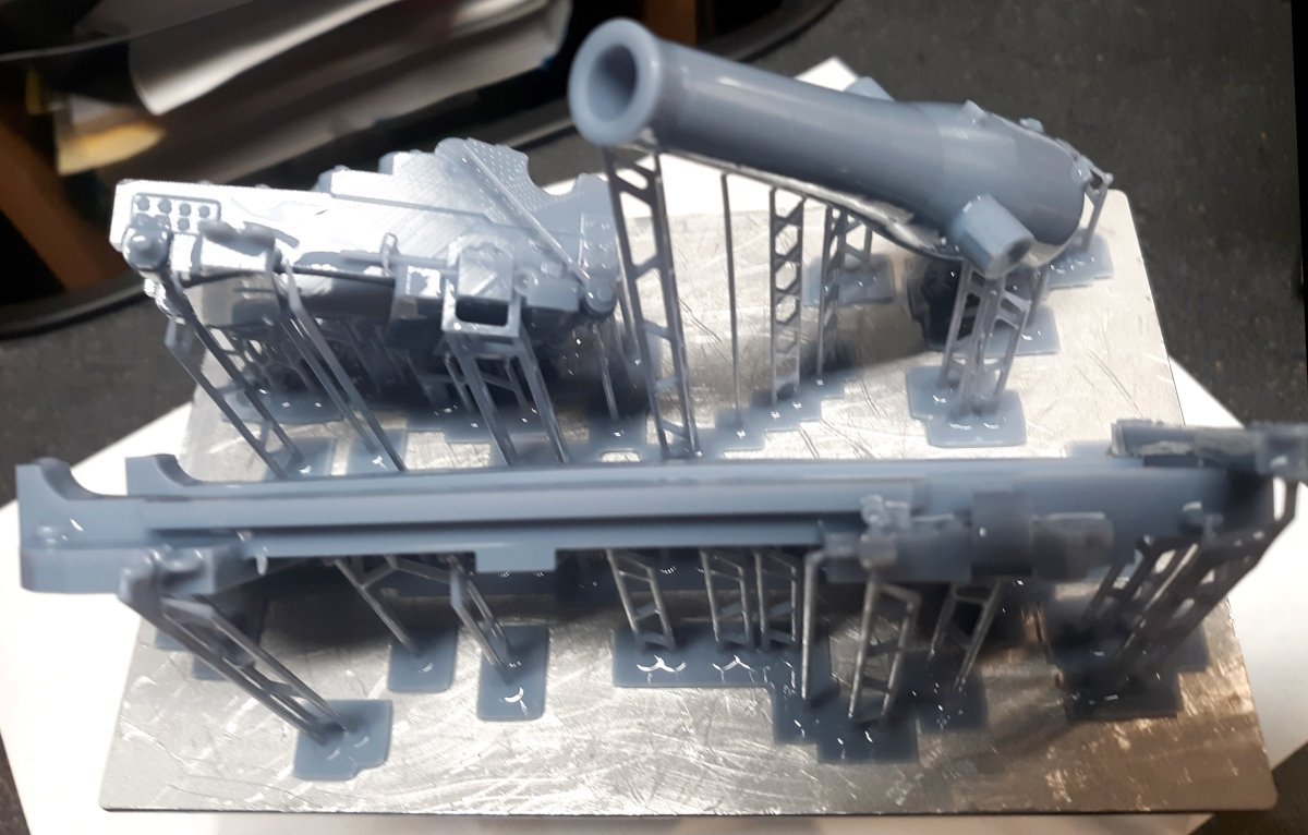
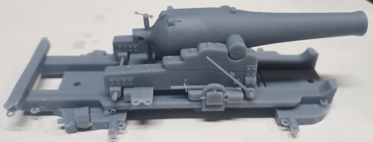

- 553 replies
-
- 4
-
-

-
- sloop of war
- constellation
- (and 3 more)
-
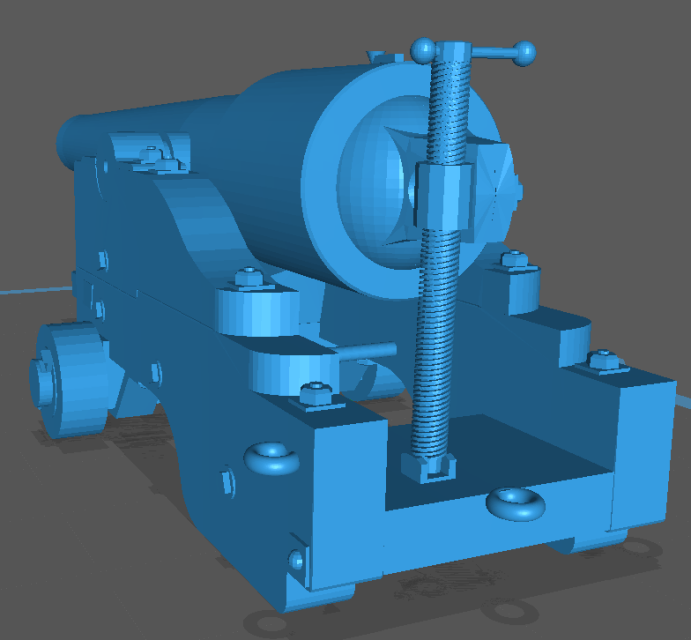
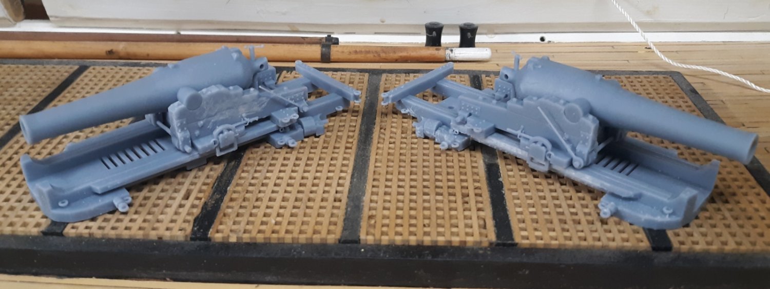
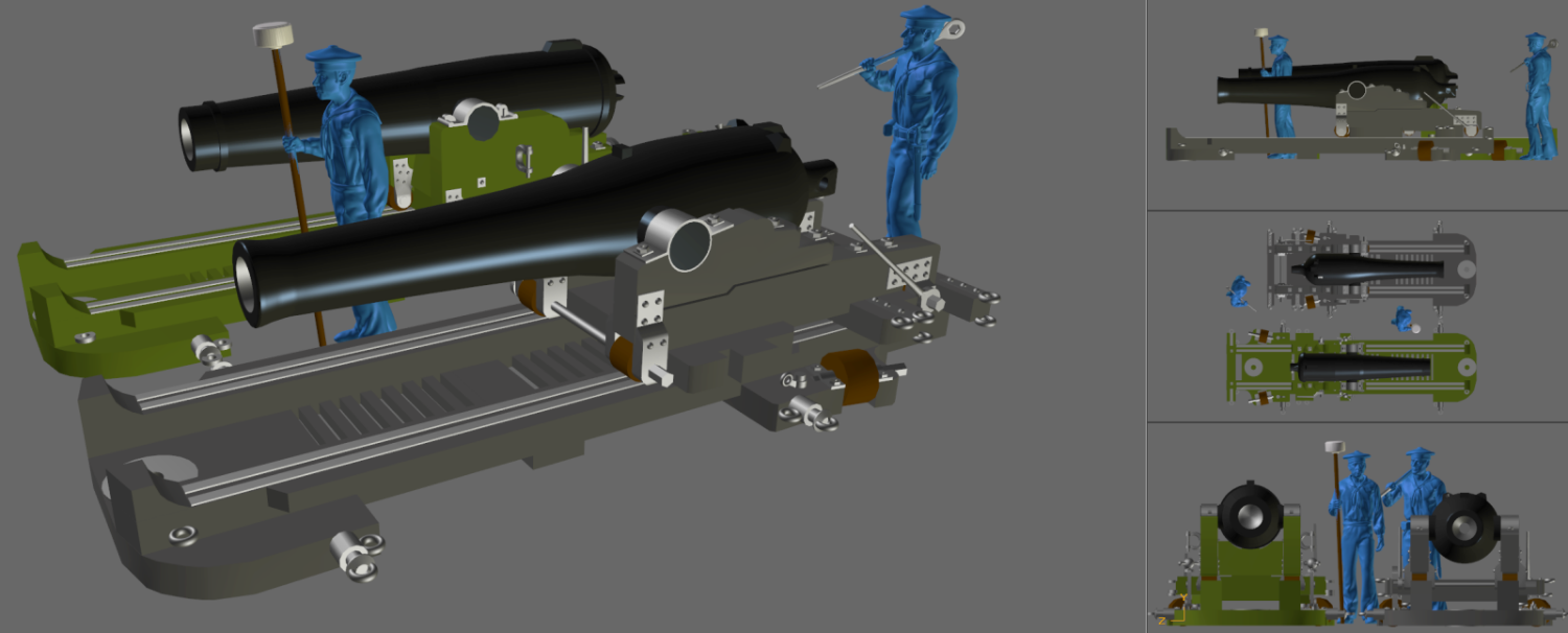
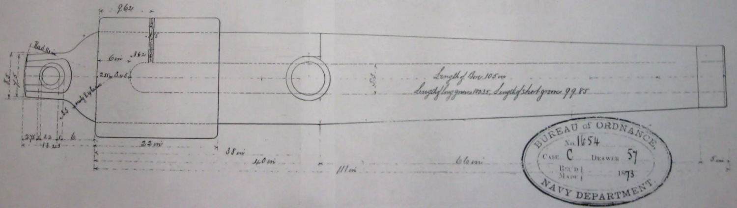
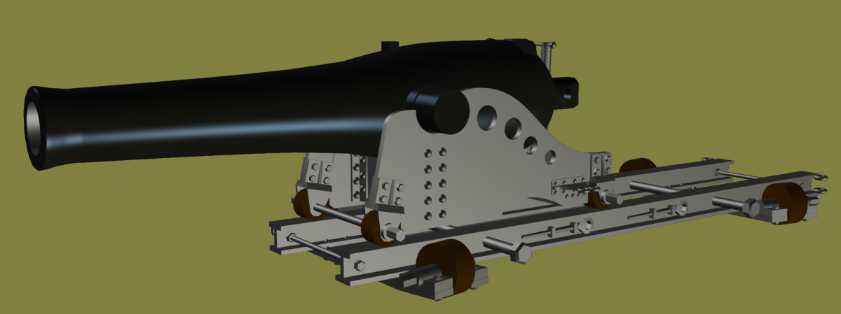
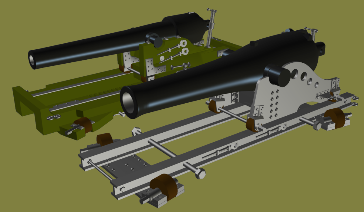
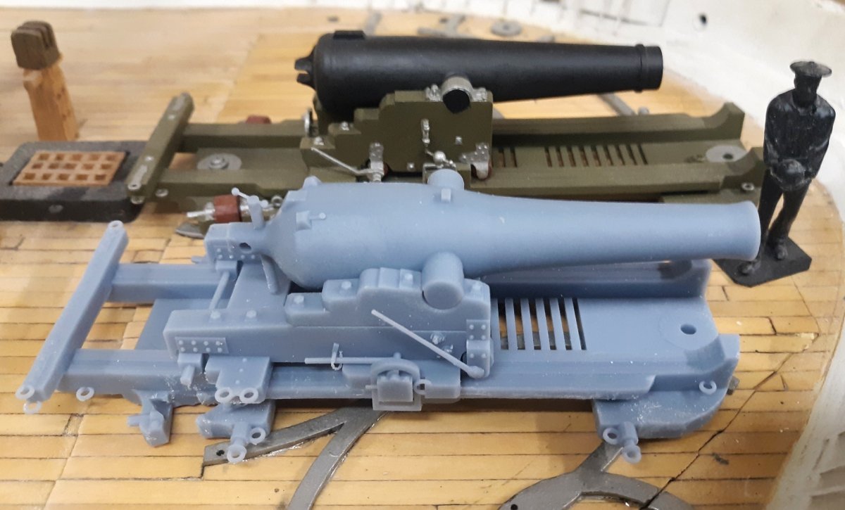
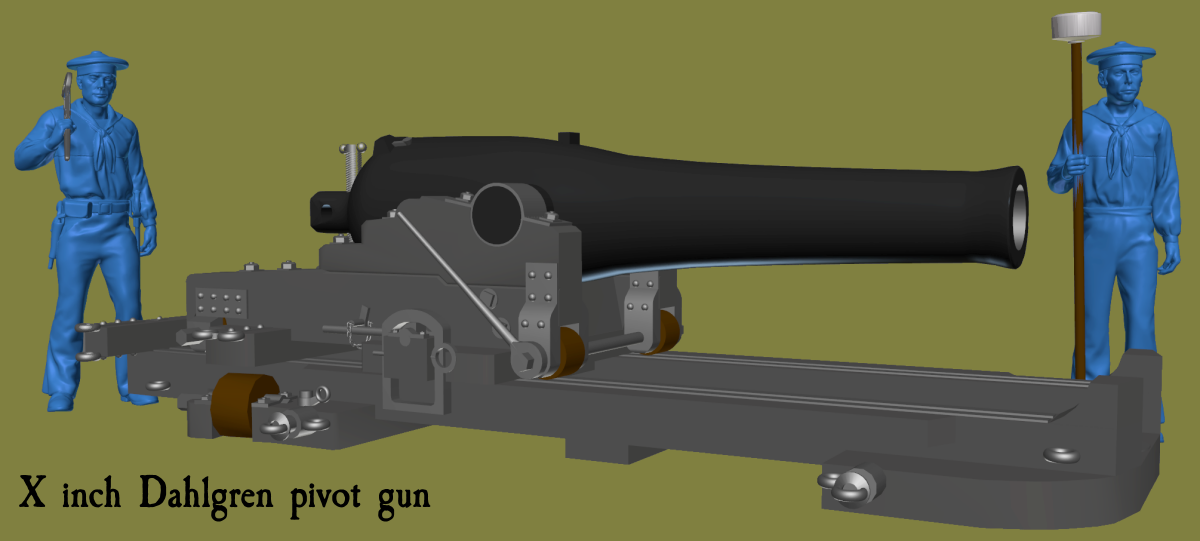
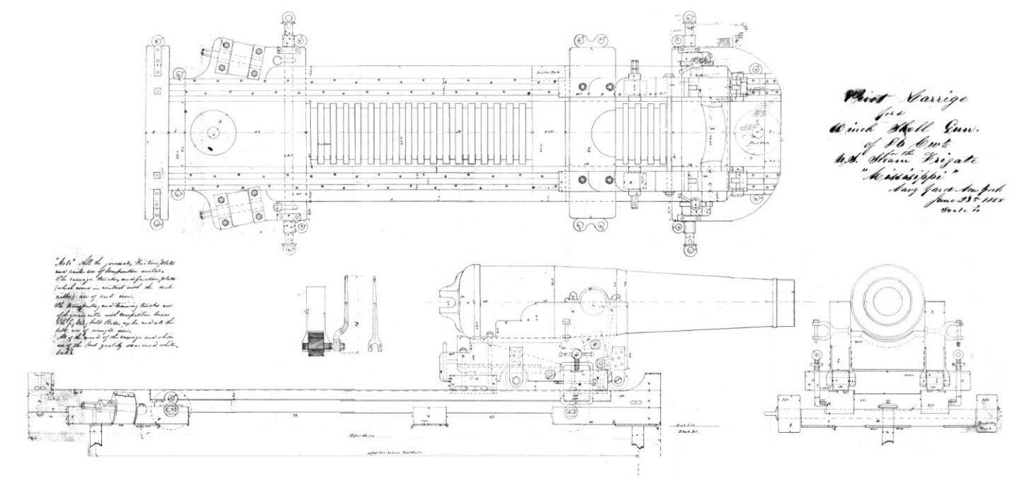
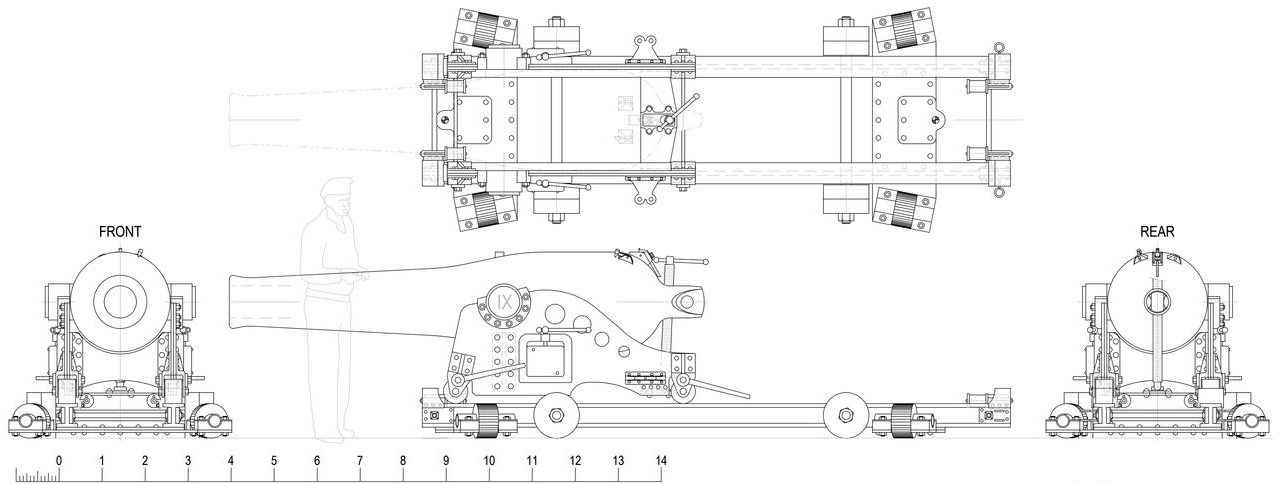
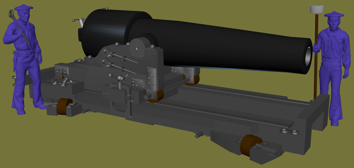
I started a "build log" just for this Naval Gun project, here as well as on my website, mainly to not clutter Constellation's log with all this non-pertinent gun stuff. But one gun I'm working on brings me back here, as it may mean a change to the Constellation model. I'm modeling a 10 inch Dahlgren on a pivot carriage and it got me thinking about Constellation's "10 inch guns on pivot carriages." The Mississippi plan, dated June 23 1855 shows a 10" gun of 86cwt (8600 pounds). The ship's restoration folks presume that Constellation got the same thing because they looked for a 10" pivot gun at the Archives, and that's the plan they found. Constellation was launched on August 26 1854, and commissioned on July 28 1855. Dahlgren's drawing, on-the-other-hand, is from July 31 1850, 5 years prior, and refers to the pivot gun simply as a "10 inch gun on pivot carriage." Without any documentation stating exactly which 10 inch pivot gun the ship was issued, how do I know? Furthermore, a 10 inch Dahlgren tube weighed 12,000 pounds, 3,400 pounds more than the Mississippi gun. When the ship was leaving for the African Station on July 15 1859, her captain felt the pivot guns were too heavy, too high, and made the ship "crank," so had them taken off. I can't help but think that would be a concern regarding a pair of 12,000 pound guns compared to a pair of 8,600 pound guns. I'm trying to find out where any records regarding what guns were issued to what ships would be, and if I can access them, but at the moment, I'm personally leaning toward replacing Constellation's pivot guns with 10 inch Dahlgren pivots. Here's the 3D models of the 10 inch Dahlgren (still a WIP), the Mississippi gun, and both together.


- 553 replies
-
- 4
-
-
- sloop of war
- constellation
- (and 3 more)
-
3D Naval Guns 1850s ~ 1870s
JerryTodd replied to JerryTodd's topic in CAD and 3D Modelling/Drafting Plans with Software
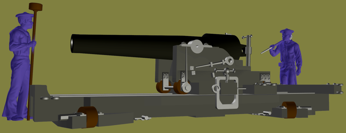
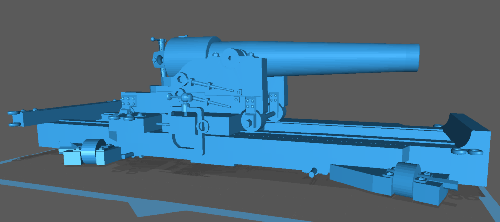
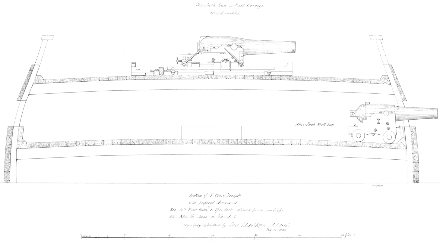
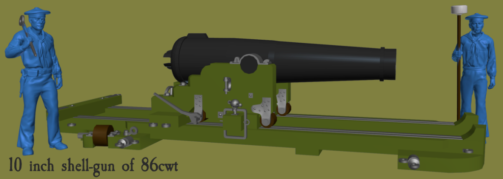
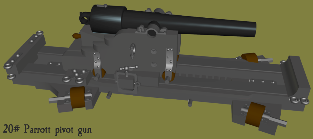
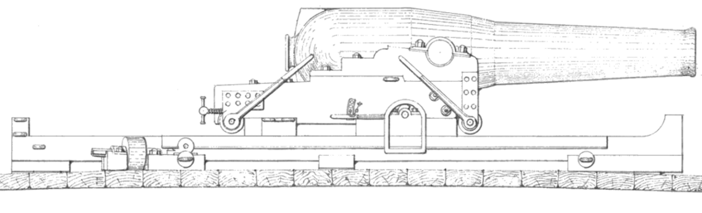
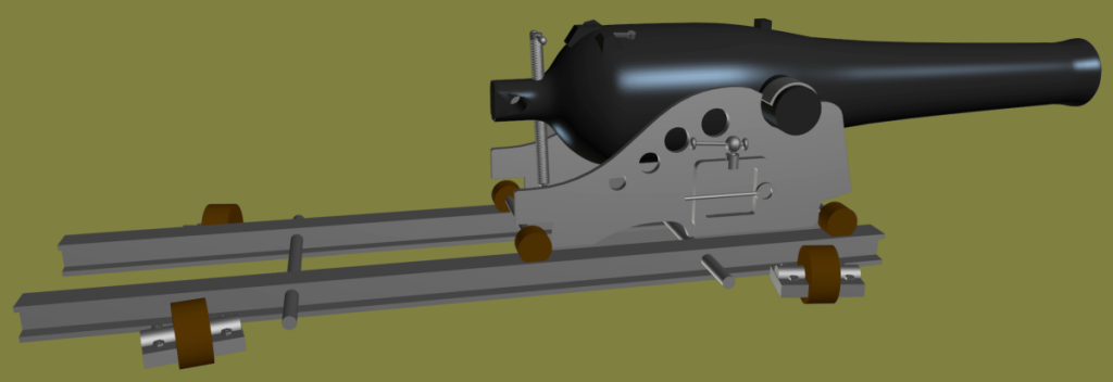
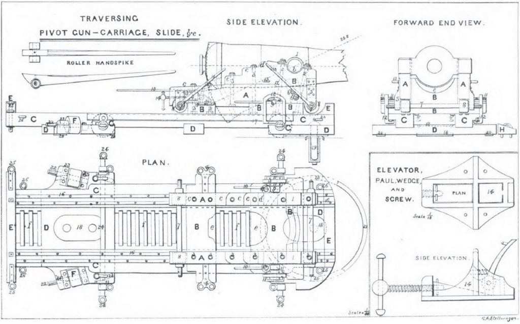
I altered the carriage for the 30# Parrott to fit the 20# gun since I have no data at all what a pivot carriage for the 20# would look like. So, that's that one done. Moving on, I poked at the XI inch Dahlgren on the iron carriage based mostly on a drawing for a sci-fi story on the Deviant Art site. I don't know their source, as most photos I can find are late 1880s, 1890s and the technology had changed some from the 1870s. The carriage looks the same, but there's springs and things the 1870 guns didn't have. It's not done, but it's getting there... This gun's for my list of Constellation's guns, and was mounted on the gun-deck opposite a 100# Parrott on a wooden pivot carriage - each with a their gun-port widened to 10 feet. Making the 60# Parrott pivot got me thinking about the gun at Cumberland's other end, a 10 inch shell-gun. I found a drawing by Dahlgren himself, dated July 1850, with a proposed armament for frigates to mount 6 10 inch shell guns on pivot on the spar deck (the 11 inch hadn't come out yet) and 26 9 inch shell-guns on the gun-deck. The Navy went with two pivots, one fore and one aft, and a mix of 8 inch shell-guns and 32# shot guns on the gun-deck. The 10 inch gun in Dahlgren's drawing is on a Traversing Pivot Gun Carriage and Slide as shown in a diagram in a Navy manual. I then used the Traversing carriage diagram to make the carriage, and took the slide from my 10" shell-gun pivot, and adjusted it to Dahlgrens drawing which was shorter, but it's the same in all other details. Spencer Tucker in his Arming the Fleet says the carriage was the same as that for for the Columbiads (the Traversing Carriage shown), but widened to accommodate the larger Dahlgren gun body. The compressor was different, and a bit fiddly, there's a lever that works it instead of the screw these carriages had later. There's a pin that hold that level connected to the carriage by a chain, and whether it was a good idea or not, I gave it a chain - we'll see how that prints. Now go to my Constellation build log to see the can of worms this opened up...
-
3D Naval Guns 1850s ~ 1870s
JerryTodd replied to JerryTodd's topic in CAD and 3D Modelling/Drafting Plans with Software
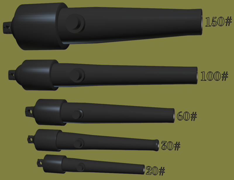
Oops, I skipped over some other Parrotts... I needed a pair of 150# Parrotts on pivots for someone modeling the Susquehanna in 1:72 scale, and I modeled it based on these images: 150# Parrott on the Wabash 150# on the Nipsic, post-war. and the 3D model... The fellow modeling the Susquehanna sent me some helpful data, I printed the 150's he'd need, but they didn't come out very well, though you'd have to know where to look. For my own list of Constellation's guns, I need a 100# Parrott for when she was a training ship in the 1870's. I based that on images of the Mendota's 100# Parrott, which if you look close, is on an identical carriage as the 150# on Wabash. and the 3D model... Unless something else pops out the blue, the only Naval Parrott left to do is the 20 pounder that Constellation had as an aft pivot gun during the war.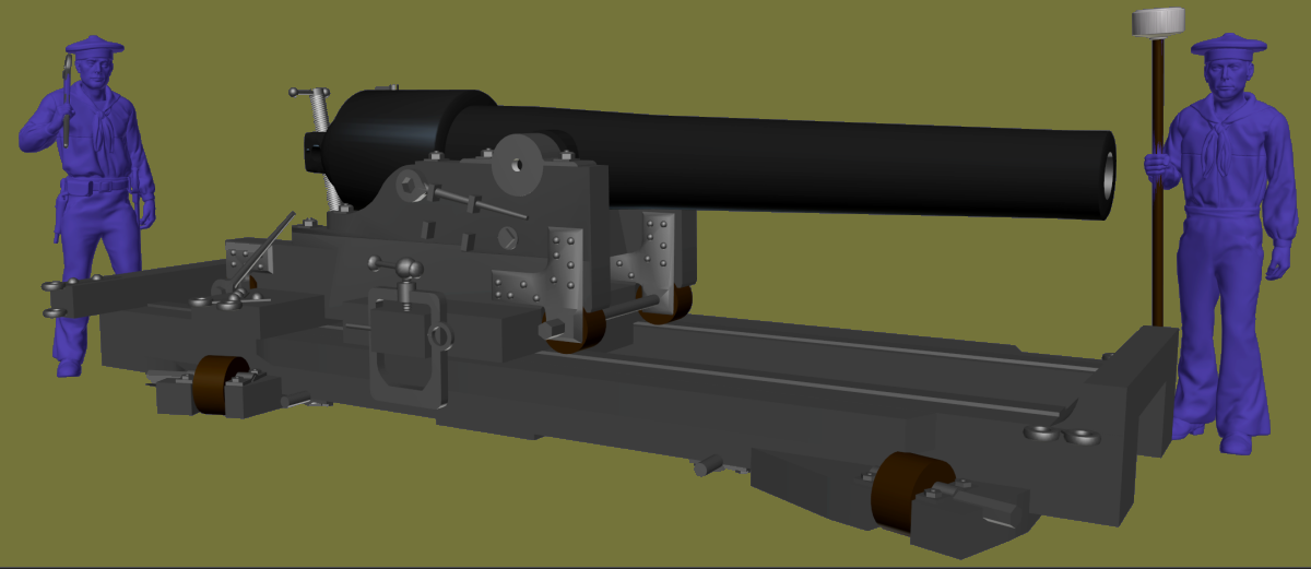
-
3D Naval Guns 1850s ~ 1870s
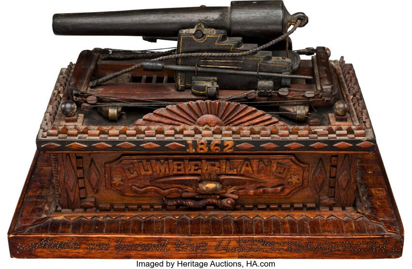
JerryTodd replied to JerryTodd's topic in CAD and 3D Modelling/Drafting Plans with Software
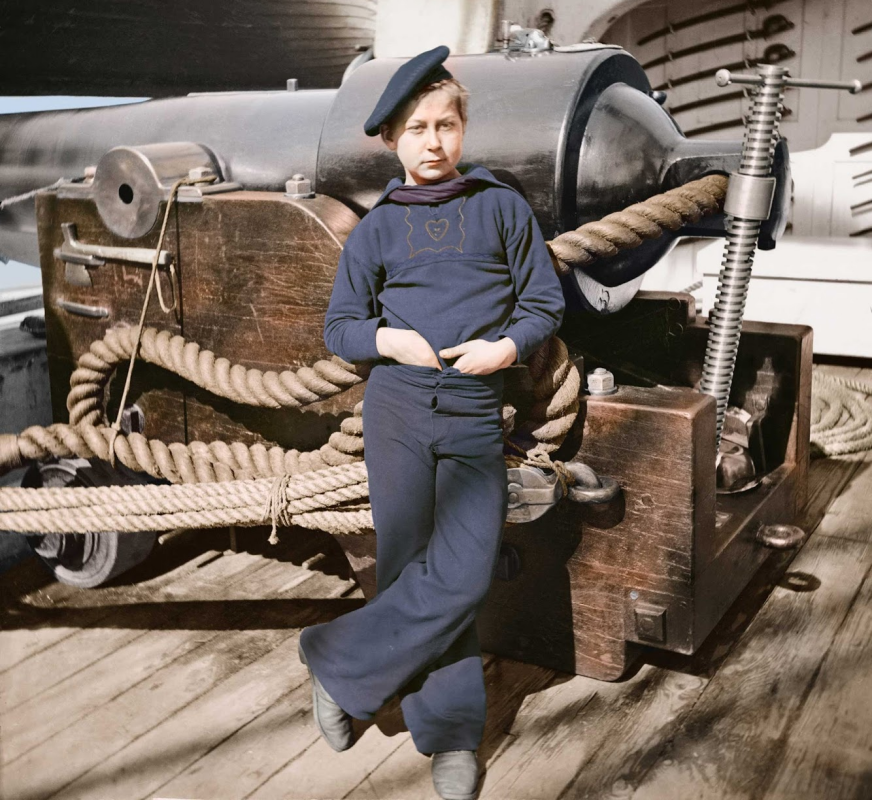
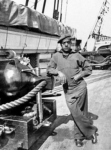
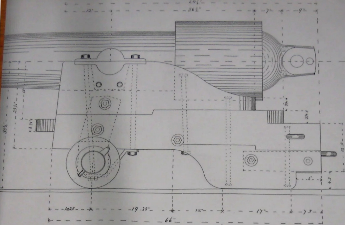
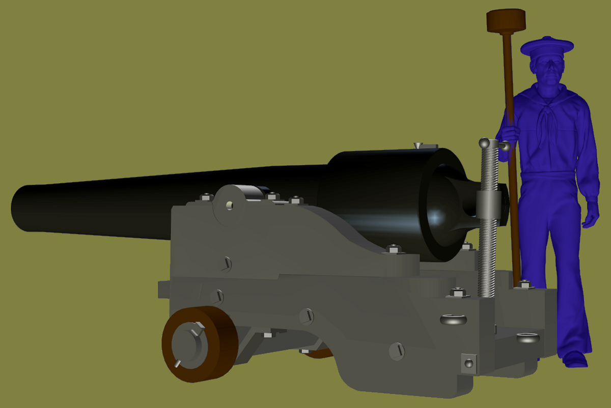
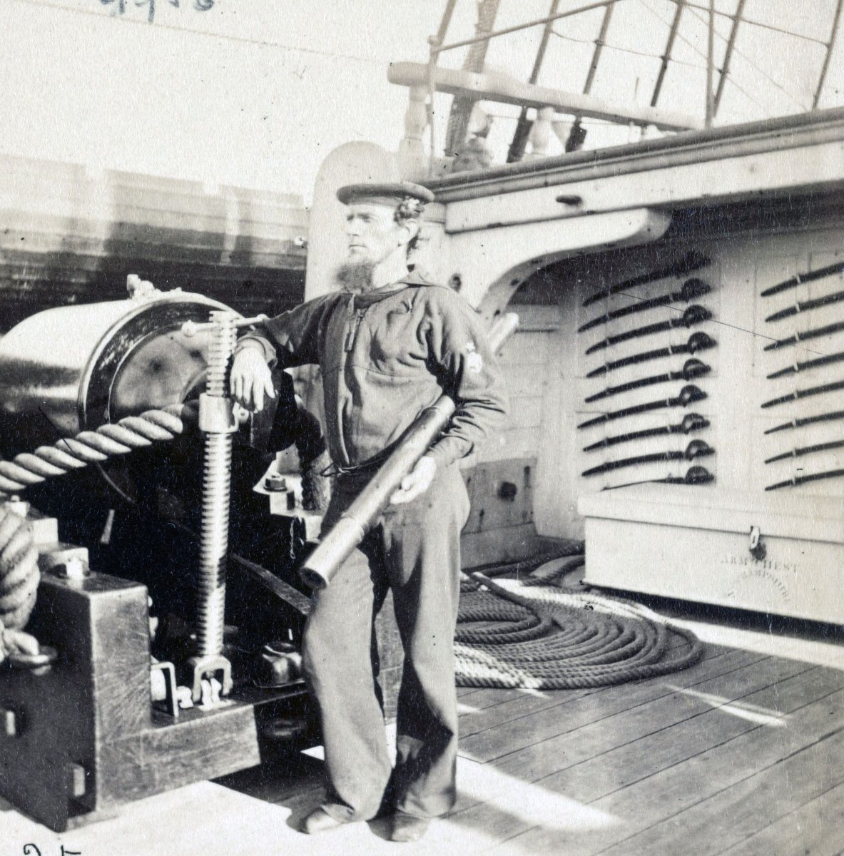
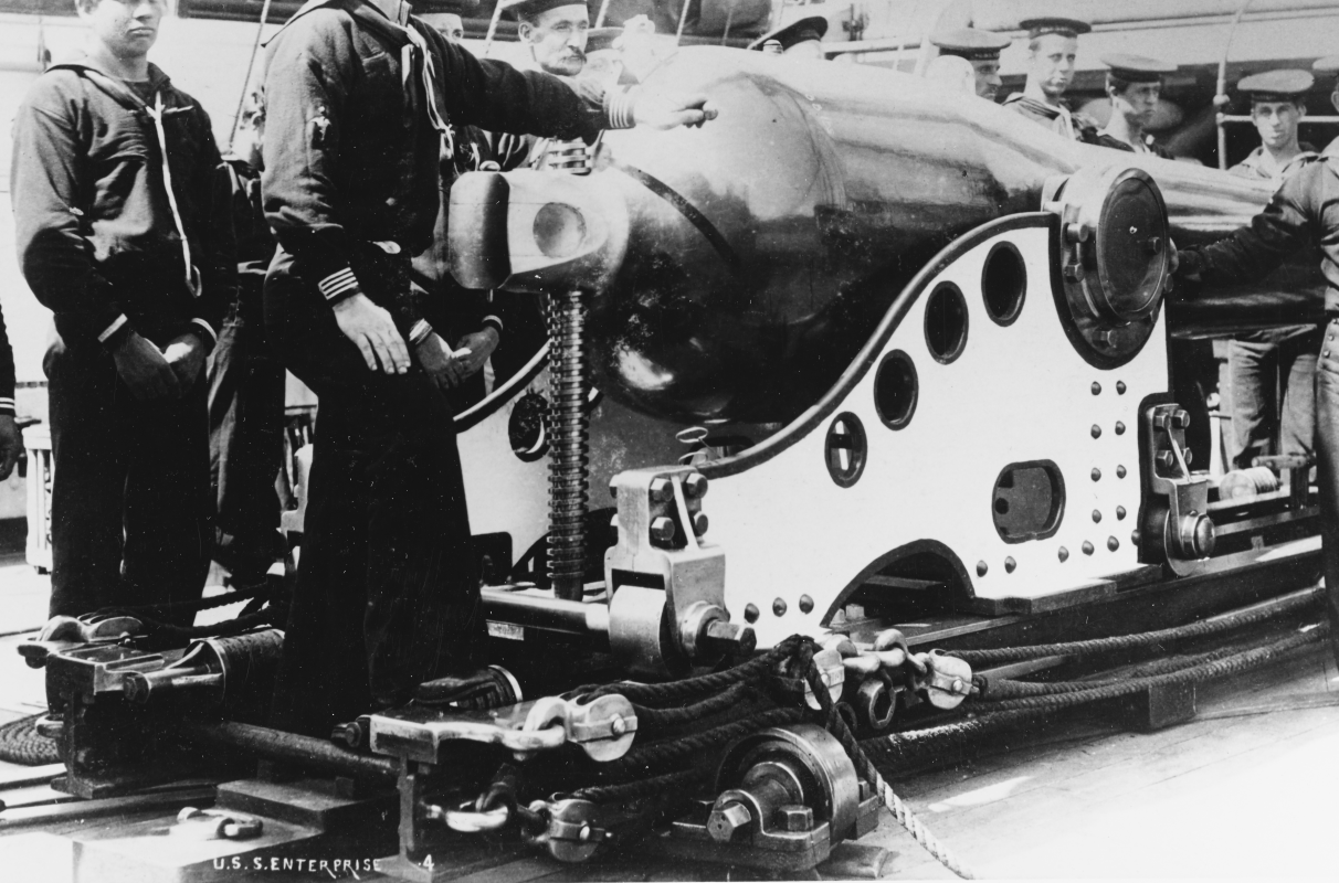
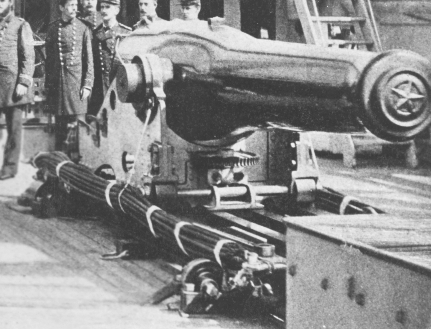
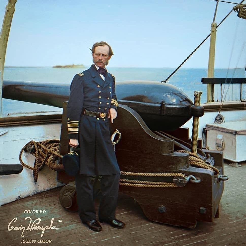
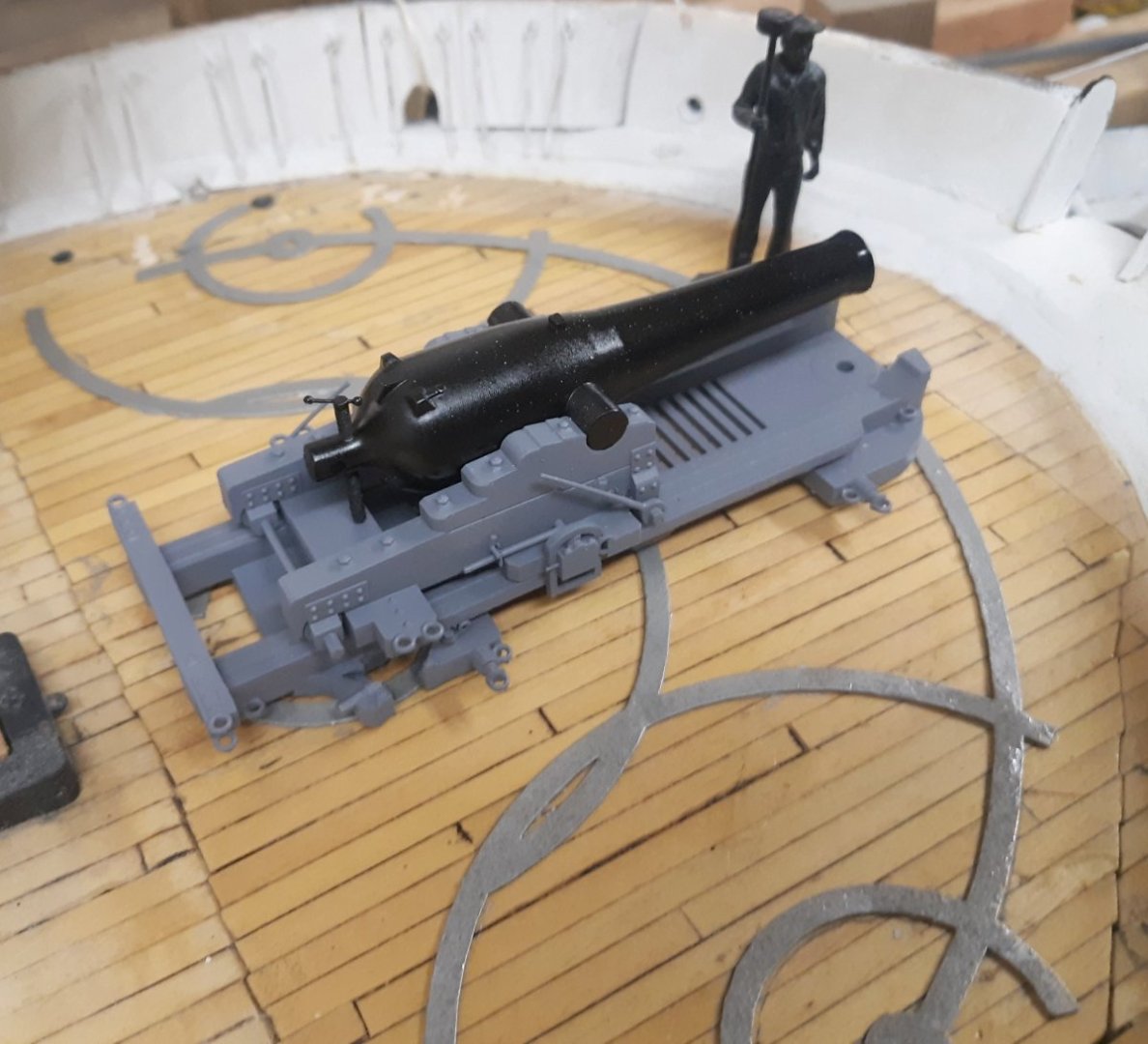
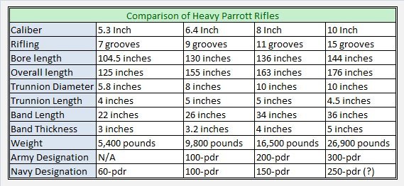
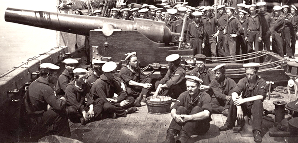
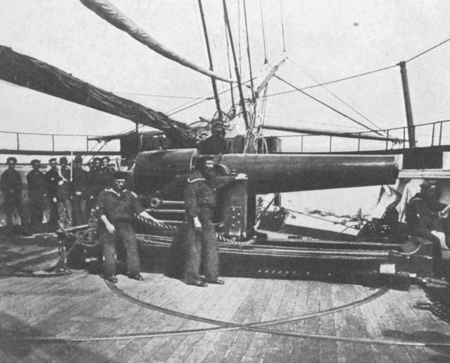
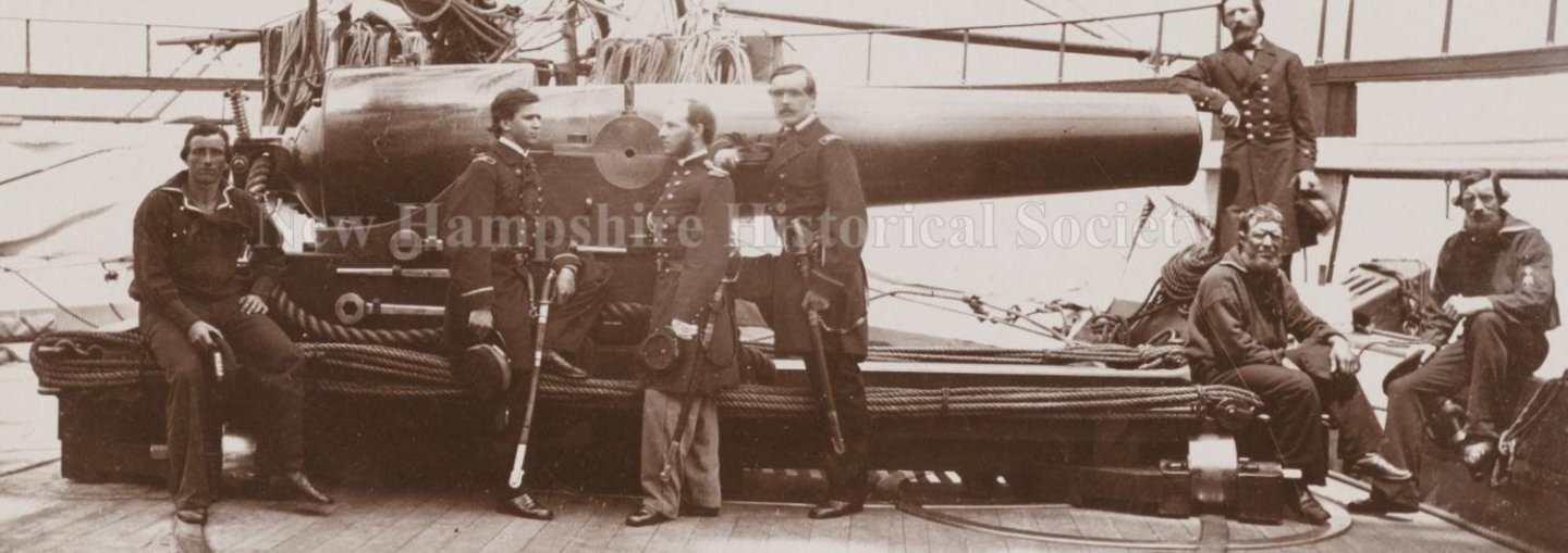
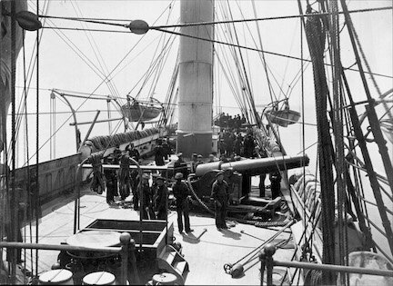
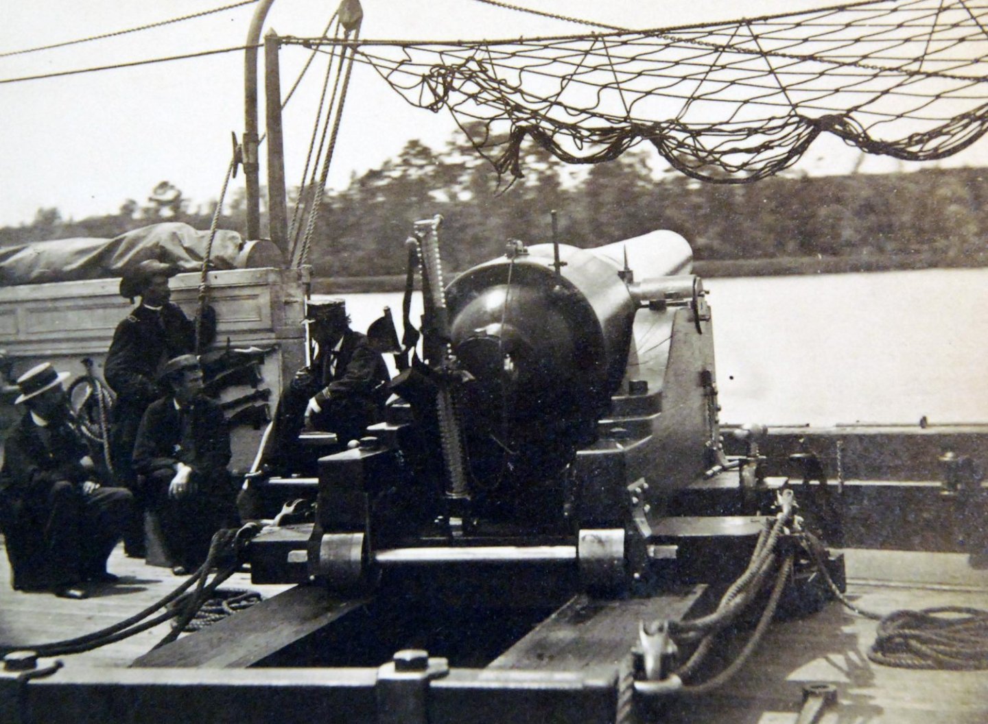
Over on Facebook's Civil War Navies group, a series of photos came up for discussion, one well-known image in this series is the "Powder Monkey," a colorized version shown here... The other images of the series have various sailors posing next to this same gun, and one sailor with a telescope that's more around the rear of the piece, showing some added details. And another with a Black sailor leaning on a IX inch Dahlgren, with this Parrott in the background. Notice in the last image there's a difference in height evident between the Parrott's and Dahlgren's carriages showing the Parrott's Marsilly carriage was fitted to it. (click the pics to see larger versions) Until now, I always figured the gun was a 30# Parrott, but when I put my model of the 30# Parrott on my Marsilly carriage, it didn't match the pictures. I thought I could easily knock out another gun for this project, but it wasn't gonna be that easy. So I put the 100# tube on and that was too big. Knowing the images were taken on board the New Hampshire, I looked into her. I learned she was armed, in addition to her broadside battery, with 4 100# Parrotts. More digging showed she received 60# Parrotts in addition to, or to replace the 100 pounders. So I went looking for data on the 60# gun. I didn't get as lucky as I did with the 20# and 30# guns, but I found a photo of a piece of a similar document from the same original source, and despite the distortion, I could read the measurements. The also had a profile view of a Marsilly type carriage with it, but the drawing of the carriage didn't match the photos, and I don't know the original source of that drawing. So, I added the 60# Parrott to my collection, and modeled my 60# Parrott on a Marsilly carriage. There was another 60# to model. When the Civil War broke out the Navy Yard at Gosport Virginia was abandoned and everything that could leave, was burned, including ships like the 120 gun Pennsylvania, the frigate Merrimack, and others. The sloop of war Cumberland was towed out by a pair of tugs, and escaped. Sent to Boston for repairs, her aft 10 inch Dahlgren was replaced with a 60# Parrott on a pivot carriage. Some reading suggests Buchanan, commanding the former Merrimack, now Virginia, targeted the Cumberland, specifically because she was known to be armed with a rifled gun. I found a reference to that gun in this commemorative item on an auction site. That item aside, I have no clue precisely what her pivot carriage looked like. So I used the carriage from my model of the IX Dahlgren pivot, altered a little to fit the very skinny Parrott rifle, so here's my take on the Cumberland's famous aft pivot. The STLs for both these models have been posted at Thingiverse for those interested.